EP2601456B1 - Accumulateur de chaleur haute température pour centrales solaires thermiques - Google Patents
Accumulateur de chaleur haute température pour centrales solaires thermiques Download PDFInfo
- Publication number
- EP2601456B1 EP2601456B1 EP11752502.2A EP11752502A EP2601456B1 EP 2601456 B1 EP2601456 B1 EP 2601456B1 EP 11752502 A EP11752502 A EP 11752502A EP 2601456 B1 EP2601456 B1 EP 2601456B1
- Authority
- EP
- European Patent Office
- Prior art keywords
- storage
- air
- temperature heat
- line
- heat
- Prior art date
- Legal status (The legal status is an assumption and is not a legal conclusion. Google has not performed a legal analysis and makes no representation as to the accuracy of the status listed.)
- Active
Links
- 238000003860 storage Methods 0.000 claims description 204
- 239000003570 air Substances 0.000 claims description 105
- 239000011232 storage material Substances 0.000 claims description 61
- 238000012546 transfer Methods 0.000 claims description 51
- 239000012782 phase change material Substances 0.000 claims description 20
- 239000007789 gas Substances 0.000 claims description 15
- 239000000463 material Substances 0.000 claims description 15
- 239000012080 ambient air Substances 0.000 claims description 14
- 238000000034 method Methods 0.000 claims description 11
- 239000004576 sand Substances 0.000 claims description 11
- 239000004575 stone Substances 0.000 claims description 9
- OKTJSMMVPCPJKN-UHFFFAOYSA-N Carbon Chemical compound [C] OKTJSMMVPCPJKN-UHFFFAOYSA-N 0.000 claims description 7
- 229910052593 corundum Inorganic materials 0.000 claims description 7
- 239000010431 corundum Substances 0.000 claims description 7
- 229910002804 graphite Inorganic materials 0.000 claims description 7
- XLYOFNOQVPJJNP-UHFFFAOYSA-N water Chemical compound O XLYOFNOQVPJJNP-UHFFFAOYSA-N 0.000 claims description 7
- 239000010439 graphite Substances 0.000 claims description 6
- -1 gravel Substances 0.000 claims description 6
- 150000003839 salts Chemical class 0.000 claims description 6
- 238000010304 firing Methods 0.000 claims description 5
- 239000007788 liquid Substances 0.000 claims description 5
- 238000007599 discharging Methods 0.000 claims description 4
- 229910052751 metal Inorganic materials 0.000 claims description 4
- 239000002184 metal Substances 0.000 claims description 4
- VNWKTOKETHGBQD-UHFFFAOYSA-N methane Chemical compound C VNWKTOKETHGBQD-UHFFFAOYSA-N 0.000 claims description 4
- 230000032258 transport Effects 0.000 claims description 4
- 239000000945 filler Substances 0.000 claims description 2
- 239000000446 fuel Substances 0.000 claims description 2
- 239000003345 natural gas Substances 0.000 claims description 2
- 238000011144 upstream manufacturing Methods 0.000 claims description 2
- 239000011833 salt mixture Substances 0.000 claims 2
- AXCZMVOFGPJBDE-UHFFFAOYSA-L calcium dihydroxide Chemical compound [OH-].[OH-].[Ca+2] AXCZMVOFGPJBDE-UHFFFAOYSA-L 0.000 claims 1
- 229910001861 calcium hydroxide Inorganic materials 0.000 claims 1
- 239000000920 calcium hydroxide Substances 0.000 claims 1
- 229910052987 metal hydride Inorganic materials 0.000 claims 1
- 150000004681 metal hydrides Chemical class 0.000 claims 1
- 239000010457 zeolite Substances 0.000 claims 1
- 230000015654 memory Effects 0.000 description 30
- 238000005338 heat storage Methods 0.000 description 27
- 238000013461 design Methods 0.000 description 12
- 230000008901 benefit Effects 0.000 description 9
- 230000000694 effects Effects 0.000 description 5
- 238000005457 optimization Methods 0.000 description 5
- 230000008569 process Effects 0.000 description 4
- 239000007787 solid Substances 0.000 description 4
- 238000010612 desalination reaction Methods 0.000 description 3
- 230000005611 electricity Effects 0.000 description 3
- 230000005484 gravity Effects 0.000 description 3
- 238000010438 heat treatment Methods 0.000 description 3
- 238000004519 manufacturing process Methods 0.000 description 3
- 238000011084 recovery Methods 0.000 description 3
- 239000013535 sea water Substances 0.000 description 3
- 229910000831 Steel Inorganic materials 0.000 description 2
- 238000010276 construction Methods 0.000 description 2
- 230000008092 positive effect Effects 0.000 description 2
- FGIUAXJPYTZDNR-UHFFFAOYSA-N potassium nitrate Chemical compound [K+].[O-][N+]([O-])=O FGIUAXJPYTZDNR-UHFFFAOYSA-N 0.000 description 2
- 238000010248 power generation Methods 0.000 description 2
- 230000001172 regenerating effect Effects 0.000 description 2
- VWDWKYIASSYTQR-UHFFFAOYSA-N sodium nitrate Chemical compound [Na+].[O-][N+]([O-])=O VWDWKYIASSYTQR-UHFFFAOYSA-N 0.000 description 2
- LPXPTNMVRIOKMN-UHFFFAOYSA-M sodium nitrite Chemical compound [Na+].[O-]N=O LPXPTNMVRIOKMN-UHFFFAOYSA-M 0.000 description 2
- 239000010959 steel Substances 0.000 description 2
- 238000013517 stratification Methods 0.000 description 2
- 239000002918 waste heat Substances 0.000 description 2
- 238000010521 absorption reaction Methods 0.000 description 1
- 230000032683 aging Effects 0.000 description 1
- 229910052783 alkali metal Inorganic materials 0.000 description 1
- 150000001340 alkali metals Chemical class 0.000 description 1
- 239000002585 base Substances 0.000 description 1
- 230000033228 biological regulation Effects 0.000 description 1
- 239000013590 bulk material Substances 0.000 description 1
- 229910052799 carbon Inorganic materials 0.000 description 1
- 239000000919 ceramic Substances 0.000 description 1
- 238000002485 combustion reaction Methods 0.000 description 1
- 238000001816 cooling Methods 0.000 description 1
- 230000008878 coupling Effects 0.000 description 1
- 238000010168 coupling process Methods 0.000 description 1
- 238000005859 coupling reaction Methods 0.000 description 1
- 230000007423 decrease Effects 0.000 description 1
- 238000010586 diagram Methods 0.000 description 1
- 238000011143 downstream manufacturing Methods 0.000 description 1
- 238000005265 energy consumption Methods 0.000 description 1
- 238000004146 energy storage Methods 0.000 description 1
- 230000002349 favourable effect Effects 0.000 description 1
- 239000010438 granite Substances 0.000 description 1
- 239000008187 granular material Substances 0.000 description 1
- 239000007770 graphite material Substances 0.000 description 1
- 238000002347 injection Methods 0.000 description 1
- 239000007924 injection Substances 0.000 description 1
- 238000009434 installation Methods 0.000 description 1
- 238000009413 insulation Methods 0.000 description 1
- 230000007774 longterm Effects 0.000 description 1
- 235000014380 magnesium carbonate Nutrition 0.000 description 1
- ZLNQQNXFFQJAID-UHFFFAOYSA-L magnesium carbonate Chemical compound [Mg+2].[O-]C([O-])=O ZLNQQNXFFQJAID-UHFFFAOYSA-L 0.000 description 1
- 239000001095 magnesium carbonate Substances 0.000 description 1
- 229910000021 magnesium carbonate Inorganic materials 0.000 description 1
- 239000004579 marble Substances 0.000 description 1
- 238000002156 mixing Methods 0.000 description 1
- 238000012986 modification Methods 0.000 description 1
- 230000004048 modification Effects 0.000 description 1
- 239000004745 nonwoven fabric Substances 0.000 description 1
- 239000010450 olivine Substances 0.000 description 1
- 229910052609 olivine Inorganic materials 0.000 description 1
- 239000002245 particle Substances 0.000 description 1
- 238000005192 partition Methods 0.000 description 1
- 235000010333 potassium nitrate Nutrition 0.000 description 1
- 230000005855 radiation Effects 0.000 description 1
- 239000012266 salt solution Substances 0.000 description 1
- 235000010344 sodium nitrate Nutrition 0.000 description 1
- 235000010288 sodium nitrite Nutrition 0.000 description 1
- 239000000243 solution Substances 0.000 description 1
- 230000035882 stress Effects 0.000 description 1
Images


Classifications
-
- F—MECHANICAL ENGINEERING; LIGHTING; HEATING; WEAPONS; BLASTING
- F28—HEAT EXCHANGE IN GENERAL
- F28D—HEAT-EXCHANGE APPARATUS, NOT PROVIDED FOR IN ANOTHER SUBCLASS, IN WHICH THE HEAT-EXCHANGE MEDIA DO NOT COME INTO DIRECT CONTACT
- F28D17/00—Regenerative heat-exchange apparatus in which a stationary intermediate heat-transfer medium or body is contacted successively by each heat-exchange medium, e.g. using granular particles
- F28D17/04—Distributing arrangements for the heat-exchange media
-
- F—MECHANICAL ENGINEERING; LIGHTING; HEATING; WEAPONS; BLASTING
- F24—HEATING; RANGES; VENTILATING
- F24S—SOLAR HEAT COLLECTORS; SOLAR HEAT SYSTEMS
- F24S60/00—Arrangements for storing heat collected by solar heat collectors
-
- F—MECHANICAL ENGINEERING; LIGHTING; HEATING; WEAPONS; BLASTING
- F03—MACHINES OR ENGINES FOR LIQUIDS; WIND, SPRING, OR WEIGHT MOTORS; PRODUCING MECHANICAL POWER OR A REACTIVE PROPULSIVE THRUST, NOT OTHERWISE PROVIDED FOR
- F03G—SPRING, WEIGHT, INERTIA OR LIKE MOTORS; MECHANICAL-POWER PRODUCING DEVICES OR MECHANISMS, NOT OTHERWISE PROVIDED FOR OR USING ENERGY SOURCES NOT OTHERWISE PROVIDED FOR
- F03G6/00—Devices for producing mechanical power from solar energy
-
- F—MECHANICAL ENGINEERING; LIGHTING; HEATING; WEAPONS; BLASTING
- F28—HEAT EXCHANGE IN GENERAL
- F28D—HEAT-EXCHANGE APPARATUS, NOT PROVIDED FOR IN ANOTHER SUBCLASS, IN WHICH THE HEAT-EXCHANGE MEDIA DO NOT COME INTO DIRECT CONTACT
- F28D17/00—Regenerative heat-exchange apparatus in which a stationary intermediate heat-transfer medium or body is contacted successively by each heat-exchange medium, e.g. using granular particles
-
- F—MECHANICAL ENGINEERING; LIGHTING; HEATING; WEAPONS; BLASTING
- F28—HEAT EXCHANGE IN GENERAL
- F28D—HEAT-EXCHANGE APPARATUS, NOT PROVIDED FOR IN ANOTHER SUBCLASS, IN WHICH THE HEAT-EXCHANGE MEDIA DO NOT COME INTO DIRECT CONTACT
- F28D20/00—Heat storage plants or apparatus in general; Regenerative heat-exchange apparatus not covered by groups F28D17/00 or F28D19/00
- F28D20/0034—Heat storage plants or apparatus in general; Regenerative heat-exchange apparatus not covered by groups F28D17/00 or F28D19/00 using liquid heat storage material
-
- F—MECHANICAL ENGINEERING; LIGHTING; HEATING; WEAPONS; BLASTING
- F28—HEAT EXCHANGE IN GENERAL
- F28D—HEAT-EXCHANGE APPARATUS, NOT PROVIDED FOR IN ANOTHER SUBCLASS, IN WHICH THE HEAT-EXCHANGE MEDIA DO NOT COME INTO DIRECT CONTACT
- F28D20/00—Heat storage plants or apparatus in general; Regenerative heat-exchange apparatus not covered by groups F28D17/00 or F28D19/00
- F28D20/0056—Heat storage plants or apparatus in general; Regenerative heat-exchange apparatus not covered by groups F28D17/00 or F28D19/00 using solid heat storage material
-
- F—MECHANICAL ENGINEERING; LIGHTING; HEATING; WEAPONS; BLASTING
- F28—HEAT EXCHANGE IN GENERAL
- F28D—HEAT-EXCHANGE APPARATUS, NOT PROVIDED FOR IN ANOTHER SUBCLASS, IN WHICH THE HEAT-EXCHANGE MEDIA DO NOT COME INTO DIRECT CONTACT
- F28D20/00—Heat storage plants or apparatus in general; Regenerative heat-exchange apparatus not covered by groups F28D17/00 or F28D19/00
- F28D20/02—Heat storage plants or apparatus in general; Regenerative heat-exchange apparatus not covered by groups F28D17/00 or F28D19/00 using latent heat
- F28D20/023—Heat storage plants or apparatus in general; Regenerative heat-exchange apparatus not covered by groups F28D17/00 or F28D19/00 using latent heat the latent heat storage material being enclosed in granular particles or dispersed in a porous, fibrous or cellular structure
-
- F—MECHANICAL ENGINEERING; LIGHTING; HEATING; WEAPONS; BLASTING
- F28—HEAT EXCHANGE IN GENERAL
- F28D—HEAT-EXCHANGE APPARATUS, NOT PROVIDED FOR IN ANOTHER SUBCLASS, IN WHICH THE HEAT-EXCHANGE MEDIA DO NOT COME INTO DIRECT CONTACT
- F28D20/00—Heat storage plants or apparatus in general; Regenerative heat-exchange apparatus not covered by groups F28D17/00 or F28D19/00
- F28D20/02—Heat storage plants or apparatus in general; Regenerative heat-exchange apparatus not covered by groups F28D17/00 or F28D19/00 using latent heat
- F28D20/028—Control arrangements therefor
-
- F—MECHANICAL ENGINEERING; LIGHTING; HEATING; WEAPONS; BLASTING
- F28—HEAT EXCHANGE IN GENERAL
- F28F—DETAILS OF HEAT-EXCHANGE AND HEAT-TRANSFER APPARATUS, OF GENERAL APPLICATION
- F28F27/00—Control arrangements or safety devices specially adapted for heat-exchange or heat-transfer apparatus
- F28F27/02—Control arrangements or safety devices specially adapted for heat-exchange or heat-transfer apparatus for controlling the distribution of heat-exchange media between different channels
-
- F—MECHANICAL ENGINEERING; LIGHTING; HEATING; WEAPONS; BLASTING
- F28—HEAT EXCHANGE IN GENERAL
- F28D—HEAT-EXCHANGE APPARATUS, NOT PROVIDED FOR IN ANOTHER SUBCLASS, IN WHICH THE HEAT-EXCHANGE MEDIA DO NOT COME INTO DIRECT CONTACT
- F28D20/00—Heat storage plants or apparatus in general; Regenerative heat-exchange apparatus not covered by groups F28D17/00 or F28D19/00
- F28D2020/0065—Details, e.g. particular heat storage tanks, auxiliary members within tanks
- F28D2020/0069—Distributing arrangements; Fluid deflecting means
-
- F—MECHANICAL ENGINEERING; LIGHTING; HEATING; WEAPONS; BLASTING
- F28—HEAT EXCHANGE IN GENERAL
- F28D—HEAT-EXCHANGE APPARATUS, NOT PROVIDED FOR IN ANOTHER SUBCLASS, IN WHICH THE HEAT-EXCHANGE MEDIA DO NOT COME INTO DIRECT CONTACT
- F28D20/00—Heat storage plants or apparatus in general; Regenerative heat-exchange apparatus not covered by groups F28D17/00 or F28D19/00
- F28D2020/0065—Details, e.g. particular heat storage tanks, auxiliary members within tanks
- F28D2020/0078—Heat exchanger arrangements
-
- Y—GENERAL TAGGING OF NEW TECHNOLOGICAL DEVELOPMENTS; GENERAL TAGGING OF CROSS-SECTIONAL TECHNOLOGIES SPANNING OVER SEVERAL SECTIONS OF THE IPC; TECHNICAL SUBJECTS COVERED BY FORMER USPC CROSS-REFERENCE ART COLLECTIONS [XRACs] AND DIGESTS
- Y02—TECHNOLOGIES OR APPLICATIONS FOR MITIGATION OR ADAPTATION AGAINST CLIMATE CHANGE
- Y02E—REDUCTION OF GREENHOUSE GAS [GHG] EMISSIONS, RELATED TO ENERGY GENERATION, TRANSMISSION OR DISTRIBUTION
- Y02E10/00—Energy generation through renewable energy sources
- Y02E10/40—Solar thermal energy, e.g. solar towers
- Y02E10/46—Conversion of thermal power into mechanical power, e.g. Rankine, Stirling or solar thermal engines
-
- Y—GENERAL TAGGING OF NEW TECHNOLOGICAL DEVELOPMENTS; GENERAL TAGGING OF CROSS-SECTIONAL TECHNOLOGIES SPANNING OVER SEVERAL SECTIONS OF THE IPC; TECHNICAL SUBJECTS COVERED BY FORMER USPC CROSS-REFERENCE ART COLLECTIONS [XRACs] AND DIGESTS
- Y02—TECHNOLOGIES OR APPLICATIONS FOR MITIGATION OR ADAPTATION AGAINST CLIMATE CHANGE
- Y02E—REDUCTION OF GREENHOUSE GAS [GHG] EMISSIONS, RELATED TO ENERGY GENERATION, TRANSMISSION OR DISTRIBUTION
- Y02E60/00—Enabling technologies; Technologies with a potential or indirect contribution to GHG emissions mitigation
- Y02E60/14—Thermal energy storage
-
- Y—GENERAL TAGGING OF NEW TECHNOLOGICAL DEVELOPMENTS; GENERAL TAGGING OF CROSS-SECTIONAL TECHNOLOGIES SPANNING OVER SEVERAL SECTIONS OF THE IPC; TECHNICAL SUBJECTS COVERED BY FORMER USPC CROSS-REFERENCE ART COLLECTIONS [XRACs] AND DIGESTS
- Y02—TECHNOLOGIES OR APPLICATIONS FOR MITIGATION OR ADAPTATION AGAINST CLIMATE CHANGE
- Y02E—REDUCTION OF GREENHOUSE GAS [GHG] EMISSIONS, RELATED TO ENERGY GENERATION, TRANSMISSION OR DISTRIBUTION
- Y02E70/00—Other energy conversion or management systems reducing GHG emissions
- Y02E70/30—Systems combining energy storage with energy generation of non-fossil origin
Definitions
- the invention relates to a memory and a method for the industrial storage of thermal energy in the form of high temperature heat at a temperature level of at least 280 ° C.
- solar thermal power plants can only produce electricity, heat or steam during periods of high direct sunlight.
- the solar field There is also a need for solar-generated heat at a high temperature in a seawater desalination plant.
- the solar thermal steam generator or the solar field is oversized so that appropriate amounts of steam can be generated shortly after sunrise for electricity generation or for sea water desalination. During the lunch time, too much steam is usually generated, which is why mirror surfaces of the solar field will either be folded away or the excess heat will be stored thermally.
- the heat can be stored either in short-term stores, which are usually designed as steam stores, so-called Ruth stores, or in salt stores, in which a liquid salt solution absorbs the heat to be stored. After sunset, the heat stored in the short-term storage is released again via a heat exchanger to the water-steam circuit of the steam power plant, a thermal oil circuit or a seawater desalination plant.
- PCM storage phase change material storage
- PCM storage phase change material storage
- PCM memories such as. B. NaNO2, NaNO3 or KNO3. It is still unclear which materials could be used at higher temperatures above approx. 340 ° C and at what costs.
- a disadvantage of PCM memories is the fixing to certain temperature levels, depending on which material is used.
- PCM storage systems like with concrete storage facilities, are the many long and expensive high-pressure steam lines that have to be laid to the PCM storage system and that have to be routed through the PCM.
- the storage material is arranged together with a blower, a heat exchanger 48 and an air duct 56 within a housing 46.
- a liquid alkali metal flows through the heat exchanger 48, where it emits heat to the air circulating within the housing in a closed circuit.
- the air heated in this way flows through a bed of gravel, which is thereby heated.
- a heat accumulator is known in which several solid bodies with parallel channels are used as the storage medium.
- a heat exchanger is provided in the center of the heat accumulator.
- the storage medium is loaded and unloaded via air circulating in a closed circuit within the heat store.
- a disadvantage of this system is the large external dimensions of the housing, because in addition to the actual storage medium, air channels, a blower and a heat exchanger have to be accommodated inside the housing. This increases costs and reduces the efficiency of the storage.
- a storage medium (sand) for storing heat is actively moved and countercurrent to hot air.
- a high-temperature heat storage means one or more storage modules including the associated periphery (heat exchanger, blower, lines, flaps etc.).
- a storage module comprises a gas-tight housing, inside of which there are one or more storage media. These storage media can be loaded or unloaded via feed line (s) and discharge line (s).
- the storage system is said to cause low investment and operating costs.
- the object is achieved by a method according to claim 1 or by a high-temperature heat store according to claim 3.
- the storage module is filled with a porous and / or granular storage material, such as sand, gravel, stone, corundum and / or graphite.
- This porous and / or granular storage material absorbs the heat from the air flowing through very quickly and with a low temperature difference (degree).
- the air is moved at ambient pressure or at slight overpressures, so that neither the air channels and the storage module must be designed even for higher pressures above 2 - 3 bar abs .
- the blower (fan or fan) used to convey the air through the high-temperature heat store according to the invention only has to convey cold ambient air, so that commercially available and inexpensive components can be used. This lowers costs and significantly increases availability.
- the heat is discharged (unloading) analogously, i.e. cold air, preferably ambient air, is passed through the storage medium and absorbs the heat present in the storage module.
- the hot air is then passed through suitable channels to a heat exchanger, which emits the heat back to a molten salt, thermal oil or another medium or preferably water or steam.
- the advantage of this system compared to other heat storage systems is that with sand, gravel, stone or corundum, and possibly also graphite, very inexpensive and widely available heat storage materials can be used. These materials have a very high loading and unloading cycle stability over wide temperature ranges and can be used continuously in any technically interesting temperature range.
- the heat is brought to the heat storage material via air at low pressures as a medium that can be easily transported by blowers. The heat transfer between air and the heat storage material is very good due to the flow around the heat storage material.
- Another possible advantageous embodiment provides for the recovery of the residual heat of the exhaust air flow.
- the heat recovery allows longer unloading operations and increases the efficiency of the overall system.
- such an air-air heat exchanger is easy to master.
- part of the air flow can also be circulated. This can either be implemented as part of the entire system or just through the heat exchanger.
- the system's air ducts can be inexpensively manufactured from standard components and materials.
- Heat exchanger systems customary on the market e.g. steam-air heat exchangers
- other modified waste heat boiler systems available on the market can be used as heat exchangers.
- an additional burner or an additional firing with conventional fuels such as natural gas or oil the loading and unloading process can be optimized and operationally stabilized.
- this system can also be kept in acceptable sizes and sizes in its required volume and the required areas.
- Another application of this method or system is the direct supply of warmed up hot air e.g. from solar power plants, such as tower power plants, or the exhaust air from hot air turbines or hot exhaust gases from gas turbines into the air duct (second supply line) of the system after that in the second supply line existing blower.
- warmed up hot air e.g. from solar power plants, such as tower power plants, or the exhaust air from hot air turbines or hot exhaust gases from gas turbines into the air duct (second supply line) of the system after that in the second supply line existing blower.
- the corresponding heat can be introduced into the storage system in a simple manner and without impairing the fan.
- the blower can be driven accordingly and thereby promotes a corresponding air flow from the environment, which then mixes with the supplied flows. It is even conceivable that the fan is not required if, for example, the exhaust gas temperature of a gas turbine is high enough and there is a correspondingly high exhaust gas pressure which is sufficient to overcome the pressure loss through the storage system.
- the heat from warm or hot exhaust air streams can also be sensibly stored or used in industrial areas using this system.
- the storage material can also be optimized in terms of material and / or layer structure.
- This optimization can, for example, provide that instead of sand, gravel, corundum or graphite, closed spheres that are filled with a phase change material (PCM) are used for a layer of the storage material.
- PCM phase change material
- the storage material located in the storage module or modules in the form of a storage area, which can be arranged, for example, like a partition between the floor and ceiling of the housing.
- the storage area can also be arranged horizontally / horizontally. This has several positive effects.
- the arrangement of the storage material in the form of one or more storage areas ensures that the flow resistance for the heat transfer medium becomes very low when it flows through the storage areas. This results from the fact that an inlet area and an outlet area of the at least one storage area are very large compared to the flow cross section in the feed line or in the discharge line.
- the heat transfer medium therefore flows through the at least one storage area at a very low speed and there are only very slight pressure losses when flowing through the at least one storage area.
- the heat transfer medium may flow through different storage walls several times on its way from the feed line to the discharge line. If the heat transfer medium flows successively through several storage areas, for example also arranged as a cascade, then the different storage areas have different temperatures, so that the energy loss is minimized when the cold heat carrier flows through the storage walls in the opposite direction of flow when the storage device is discharged.
- the initially cold heat transfer medium is then warmed up by a storage wall, the temperature of which is only slightly higher than the temperature of the cold heat transfer medium.
- the heat carrier preheated in this way then flows through a second storage area, the temperature of which is somewhat higher than that of the first storage area, and so on.
- the storage module is filled with a granular storage medium and this granular storage medium is usually free-flowing or pourable, in many cases it is necessary that at least the entry and exit surfaces of the storage surfaces be covered by a net, a grid, a perforated plate, a fleece and / or another gas-permeable porous interface is limited. This ensures that the storage material remains in the intended location. You can imagine a storage wall similar to a wire mesh basket filled with stones or gravel or gravel.
- This support structure can be formed, for example, by a plurality of metal rods arranged parallel to one another, which, for example, supports a grid or a perforated plate or a fleece which prevents the storage material located in the storage areas from falling out. It is of course, to ensure that the support structure reduces the cross-sectional area of the storage area as little as possible in order to maintain the advantages mentioned of a low flow rate and low pressure losses.
- a particularly advantageous embodiment in this regard provides that the storage area is designed as a vertical wall and that a plurality of slats arranged one above the other in the vertical direction are provided within the storage areas.
- These slats can be made of sheet steel, for example, and serve to hold the storage material in position.
- These slats can be designed, for example, as inclined steel sheets. Due to the inclined slats, gravity pushes the storage material into the center of the storage area.
- a support structure on the entry surfaces and on the exit surfaces can thus be dispensed with.
- a net, a grid, a perforated plate or a fleece is not required on the entry and exit surfaces. This further reduces the flow resistance of the storage area and also reduces the manufacturing costs.
- this storage wall looks like a large number of vertically stacked cones, the slats ensuring that the various cones have the same footprint, so that a vertical storage wall with an approximate constant wall thickness is created.
- a further advantageous embodiment provides that the at least one storage area, with the exception of the entry area and the exit area, is delimited by gas-tight walls. These gas-tight walls are required to ensure that the heat transfer medium must flow through the storage area and thus a short circuit between the supply line and the discharge line is avoided, bypassing at least one storage area. This is the only way to ensure that the entire storage material stored in the storage module is also used to store sensitive heat and that the efficiency and performance of the storage module are high.
- PCM phase change material
- the storage material prefferably be layered horizontally or vertically within a storage wall and for the diameter of the storage material used or the storage material used itself to be changed from layer to layer.
- the thermal properties of the storage material can be adapted to the fluidic and thermal conditions prevailing in the respective zone of the storage wall, and a further optimization of the performance of the storage module can thereby be achieved.
- a space can be provided within the storage area forming structure of small tubes, Raschig rings, three-dimensional meshes and / or other fillers can be arranged. This ensures that the storage material does not compress and segregate over time and, as a result, the flow resistance through the storage area increases in this area with compressed storage material.
- a closure element in particular a flap, is provided in the at least one feed line and / or the at least one discharge line.
- the at least one storage area can be designed in the manner of a cylindrical storage wall or in a spiral shape. It is particularly advantageous if a plurality of cylindrical storage walls are arranged concentrically with one another. This results in a very high performance with a small construction volume of the memory module and at the same time the heat transfer during loading and unloading is optimized.
- the at least one storage layer can also be designed as a cuboid, parallelepiped, cylinder, hollow cylinder and / or as a wall with a spiral base.
- a supply line and a discharge line for the heat transfer medium at any point on the housing. Care will be taken to ensure that the at least one supply line and the at least one discharge line allow a uniform flow through the storage areas and that the pressure loss of the heat transfer medium when flowing through the storage areas is also minimized. It is therefore often sensible to provide the supply line on the side and the discharge line on the top of the housing of the memory module. Of course, the supply lines and the discharge lines can also be attached at any desired point on the memory module.
- the housing preferably on the outside, is thermally insulated in order to minimize the energy losses due to radiation or convection into the surroundings.
- the memory module can be connected in series or in parallel with several similar or identical memory modules. This makes it possible to provide a high-temperature storage device which is composed of several storage modules as required.
- the memory modules can be manufactured inexpensively in standardized sizes. This modular design also simplifies transport to the installation site.
- Sand or gravel or stone or corundum or graphite or similar materials e.g. PCM
- PCM graphite or similar materials
- the memory can be built in different versions, but it has proven to be advantageous to design the individual memory modules in the form of containers with standard dimensions. Accordingly, they are easy to transport and inexpensive to manufacture. These modules can be strung together or placed on top of each other, so that the total storage capacity can be increased accordingly in a simple manner. Depending on the application, it may make sense to use both standard container designs and tank container designs, for example.
- the appropriate air ducts for the supply and exhaust air with air flaps are then connected to these storage modules.
- the memory modules can be designed such that the air duct connections are arranged above and below or to the side. This allows great flexibility with regard to the space requirement.
- FIG. 1 a is a basic embodiment of the High temperature heat storage and operation during loading are shown. Cold air from the surroundings is fed to a heat exchanger 3 by means of the blower 4 via an air duct, hereinafter also referred to as the second feed line 19, a bypass line 21 and the flap 11. Reference number 29 denotes a memory module. A flap 10 is closed during loading.
- the excess heat from the solar field is on the heat transfer medium of the solar field, for. B. steam or thermal oil, the heat exchanger 3 via a line 1 is supplied.
- the excess heat is transferred from the solar field to the air flow flowing through the heat exchanger 3.
- the cooled heat transfer medium from the solar field leaves the heat exchanger 3 via a line 2.
- the heated air is supplied to the storage module 29 via the air duct 5, a first supply line 17 and the air flap 13.
- the hot air is distributed within a housing 16 of the memory module 29 over a larger cross section and flows z. B. by perforated plates 7 or lances through the heat storage material 6.
- the housing 16 may be made of metal, concrete and / or another suitable material and, if necessary, is provided with thermal insulation (not shown).
- the heat storage material 6 can also be divided into several layers, with different layer thicknesses, different storage materials and different average diameters of the storage material. To avoid mixing, the different layers can be separated from one another by high-temperature-resistant, air-permeable nonwovens or perforated sheets or nets or porous ceramic structures.
- the hot air gives off the heat to the heat storage material 6 and leaves the storage module 29 via the first discharge line 18 and the open flap 9.
- the flaps 8, 12 and 10 are closed.
- hot air or hot exhaust gases from an upstream process can be fed directly into the storage module 29 via this line 24, so that the sensible heat contained therein is stored in the storage module 29 without the "detour" via an air / air heat exchanger can be.
- the blower 4 Since the line 24 opens downstream of the blower 4 into the second feed line 19, the blower 4 is not subjected to the high temperatures of the air or exhaust gases flowing in the line 24.
- the line 24 thus enables the coupling of sensitive heat from a gaseous medium (air or exhaust gases) at lower temperatures than in the heat exchanger 3.
- Figure 2 shows schematically the unloading of the high-temperature heat storage system Figure 1 a) , The discharge of the high temperature heat storage system after Figure 1 b) takes place in the same way with the flap 23 closed, so that a separate description is unnecessary.
- the cold air is distributed within the housing 16 via perforated sheets 7 or lances and passed through the storage medium 6 and absorbs the heat there.
- the heated air then leaves the store via the second discharge line 20 and the open flap 12 and is then led via the bypass line 21 to the heat exchanger 3, where it heats the heat transfer medium flowing in the lines 1 and 2.
- the heat exchanger 3 can basically be designed like a standard waste heat boiler after gas turbines.
- the hot air gives the heat in the heat exchanger 3 to a downstream and not shown power plant process with a Water-steam cycle from z. B. that the water is passed via line 2 into the heat exchanger 3 and leaves the heat exchanger 3 via line 1 as water vapor with correspondingly high temperatures.
- An additional firing 14 can be installed in front of the heat exchanger 3, which can serve to further increase the temperature of the air and / or to keep the heat transfer in the heat exchanger stable.
- This version with additional firing 14 is particularly advantageous when the store is so far discharged that the temperature of the air has dropped to a level that it would no longer be possible to operate the downstream power plant process properly.
- control flaps 15 are set so that the air flow and the pressure conditions are optimally distributed.
- FIG. 3 shows a corresponding basic embodiment when loading the memory with control flaps 15.
- control flaps can also be used sensibly during unloading, e.g. B. to discharge the storage section by section and to keep the air temperature level after the storage stable in the long term at a high level.
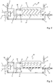
- FIG. 4 shows a plan view of a first embodiment of a memory module 29.
- the memory module 29 consists of a housing 16 into which a feed line 17 opens.
- a hot heat transfer medium such as air, can get into the interior of the housing 16 via the feed line 17.
- a discharge line 18 is provided on the side of the storage module 29 opposite the feed line 17 and is used to remove the heat carrier cooled in the storage module 29.
- a total of eight vertical storage areas 31.1 are in the housing 16 arranged until 31.8. These storage areas 31 are parallel to one another and are spaced apart from one another. They essentially consist of a storage material, such as sand, gravel, crushed stone or the like.
- the storage areas 31 are formed in the illustrated embodiment as a vertical (storage) wall; they start at the bottom 41 of the housing 16 and end at the ceiling of the housing 16. This ceiling is in Figure 4 not shown to allow a look inside the memory module 29.
- a diameter widening 33 is provided which, in the manner of a diffuser, leads to a delay in the heat transfer medium flowing through the supply line 17.
- the path of the heat transfer medium through the storage module 29 is indicated with the aid of a large number of arrows (without reference numerals). It is clear here that the heat transfer medium flows forcibly through one of the storage walls 31.1 to 31.8 in order to get from the supply line 17 to the discharge line 18.
- the end faces of the storage walls 31 are closed with gas-tight walls 35.
- a gas-tight wall 35 connects two adjacent storage layers 31 to one another.
- the storage areas are connected to one another in a gas-tight manner at the end facing the feed line 17.
- the ends of the storage areas facing the discharge line 18 are delimited by a gas-tight wall 35.
- the storage wall 31.1 is connected to the housing 16 at its end facing the discharge line 18 via a gas-tight wall 35.
- gas-tight surfaces 35 are alternately arranged on the other sides of the other storage surfaces 31.3 to 31.8.
- the hot heat transfer medium can flow from the supply line 17 only in every second intermediate space between two storage areas 31 or a storage area 31.1, 31.8 and the housing 16.
- the heat transfer medium then flows through the storage areas 31 and can then, on the other side of the storage area, flow out in the direction of the discharge line 18.
- the total of eight storage areas 31.1 to 31.8 have several advantageous properties for loading and unloading the storage material:
- the storage areas 31 form a very large entry area 37 and, since it is a straight storage wall 31, have an equally large exit area 39. This ensures that the heat transfer medium flows through the storage walls 31 at a very low speed and thus with low pressure losses can.
- the duration of the heat transfer medium in the storage area 31 is relatively long, so that good heat transfer between the gaseous heat transfer medium and the storage material 40 in the storage areas 31 can take place.
- FIG 4 the loading of the memory module 29 is shown. If the storage module is to be discharged, this can be done, for example, by reversing the direction of flow and conveying cold air into the storage module 29 through the discharge line 18. This cold air flows against the flow direction when loading the storage module 29.
- the storage walls 31 absorb most of the sensible heat stored there and leave the housing 16 as a hot heat transfer medium via the supply line 17.
- the loading and unloading of the memory module takes place via separate feed lines and discharge lines, as is the case, for example, with reference to FIG Figures 1 and 2 was explained. These additional feed and discharge lines are in the Figure 4 not shown.
- FIG. 5 is a first embodiment of a storage area enlarged and shown in a vertical section.
- the filter surface 31 is delimited at the bottom by a bottom 41 and at the top by a ceiling 43 of the housing 16. So that the storage material, which in Figure 5 is shown as pebbles, does not slide downward due to gravity, a perforated plate or a grating 45 is arranged on the inlet surface 37 and on the outlet surface 39.
- This perforated plate or grid 45 must be matched to the storage material with regard to its mesh size or the size of the holes in such a way that the storage material cannot pass through the holes or the grid 45. At the same time, care must be taken that the flow resistance through the grille 45 or the perforated plate increases only as little as possible. It is also conceivable to provide a stable grid 45 with a large mesh size and to arrange a fleece or a grid with a much smaller mesh size between the storage material and this grid 45 (not shown).
- FIG 6 Another embodiment of a storage wall 31 is shown.
- a perforated plate or a grille 45 can be dispensed with because a plurality of lamellae 47 are arranged vertically one above the other on the entry surface 37 and the exit surface 39.
- slats 47 are inclined at an angle such that the storage material does not fall outwards.
- the flow resistance of the heat transfer medium through such a storage wall 31 with the fins 47 is very low.
- such a storage area 31 can be produced very easily on site by constructing a support structure (not shown) for the slats 47 in the housing 16. The space between the fins 47 is then filled with the storage material.
- the inclination of the slats 47 must be such that, on the one hand, no storage material falls out of the side of the storage wall.
- the distance A also depends on the length of the slats and the angle of inclination of the slats. An arrangement offset to one another between the fins on the inflow side and those on the outflow side can be advantageous.
- the vertical distance A between two slats 47 is thus an important parameter for the design of a storage area 31.
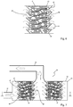
- FIG 7 shows a vertical section through an embodiment of a memory module 29, the housing 16 is cylindrical in plan view.
- the storage wall 31 is annular and is delimited in the radial direction by the previously described slats 47.
- the storage wall 31 is, as can also be seen from the section along the line AA in Figure 8 results in an annular design.
- the slats 47 are also circular in this embodiment. Via the supply line 17, the hot heat transfer medium flows into an annular space, which is delimited on the outside by the housing 16 and delimited on the inside by the storage wall 31, into the storage module 29, flows radially inwards through the storage wall 31 and leaves the centrally arranged discharge line 18 the memory module 29.
- the storage module is to be seen in the fact that the storage areas 31 ultimately consist of an inexpensive bulk material that is simple and usually metallic structure is fixed. This avoids problems such as stress cracks that would be due to the regular heating and cooling of the storage layers. It is also easily possible to replace the storage material if its thermal properties deteriorate due to aging or if the operating conditions have changed.
- FIG 9 a section through a further exemplary embodiment of a memory module 29 is shown, in which there are three filter walls 31.1, 31.2, 31.3 arranged concentrically to one another. Between the housing 16 and the outermost storage wall 31.1, the previously described cylindrical jacket-shaped inflow channel 49.1 is created. Furthermore, a further annular space 49.2 is formed between the second filter wall 31.2 and the third filter wall 31.3, which is connected to the feed line 17 and is therefore charged with hot heat transfer medium. From these two annular spaces 49.1 and 49.2, the hot heat transfer medium flows through the storage walls 31.1, 31.2 and 31.3 and flows into the centrally arranged discharge line 18. The cooled heat transfer medium, which is located in a third annular space 49.3 between the first storage area 31.1 and the second storage area 31.2 is located, into which lead 18 can be derived, a connection channel 51 for lead 18 is provided in the center of the housing 16.
- the high-temperature heat accumulator there is a regenerative or recuperative air / air heat exchanger 25 which, when the high-temperature heat accumulator is loaded, transfers heat from the still warm exhaust air from the storage module 29 flowing in the first outlet 18 to the air flowing in the second feed line 19 ( still) cold Transmits ambient air.
- the flap 23 is controlled as in connection with the Figure 1b explained.
- the ambient air sucked in by the blower 4 is thus heated via the air-air heat exchanger 25 in that the exhaust air flow in the discharge line 18 still emits residual heat before it leaves the system.
- the exhaust air flow can have temperatures of approx. 90 ° C to 250 ° C, depending on the design and parameters.
- a large part of the heat can be transferred to the inflowing ambient air via the air-air heat exchanger 25 and thus recovered. This heat remains in the system and the heat losses through the exhaust air leaving the storage module 29 via the line 22 are drastically reduced.
- the air-air heat exchanger 25 required for this can always be operated at a good operating point since the air mass flowing in via the second feed line 19 and the mass of the exhaust air flowing via the first discharge line 18 or line 22 are approximately the same.
Landscapes
- Engineering & Computer Science (AREA)
- Mechanical Engineering (AREA)
- General Engineering & Computer Science (AREA)
- Physics & Mathematics (AREA)
- Thermal Sciences (AREA)
- Chemical & Material Sciences (AREA)
- Dispersion Chemistry (AREA)
- Combustion & Propulsion (AREA)
- Sustainable Development (AREA)
- Sustainable Energy (AREA)
- Life Sciences & Earth Sciences (AREA)
- Building Environments (AREA)
- Central Heating Systems (AREA)
- Cultivation Receptacles Or Flower-Pots, Or Pots For Seedlings (AREA)
- Heat-Exchange Devices With Radiators And Conduit Assemblies (AREA)
- Greenhouses (AREA)
- Other Air-Conditioning Systems (AREA)
- Filling Or Discharging Of Gas Storage Vessels (AREA)
Claims (27)
- Méthode de stockage d'énergie thermique sous forme de chaleur haute température, dans laquelle la chaleur est délivrée dans l'air via un milieu, tel que par exemple de la vapeur d'eau, de l'eau, de l'huile thermique et/ou des sels fluides ou des mélanges de sels, au moyen d'un échangeur de chaleur (3), cet air chauffé transporte la chaleur vers le milieu de stockage (6) et délivre la chaleur au milieu de stockage (6), dans laquelle l'air, après qu'il ait délivré de la chaleur au milieu de stockage (6), quitte le milieu de stockage (6) sous la forme d'air sortant,
caractérisée en ce que
l'air ambiant sert à charger le milieu de stockage (6), l'air ambiant est prélevé dans l'environnement via un ventilateur (4) et l'air ambiant, après le ventilateur (4), est préchauffé via un échangeur de chaleur air/air (25) avec l'air d'échappement quittant le système. - Méthode selon la revendication 1, caractérisée en ce que pour décharger le milieu de stockage (6), de l'air est amené à passer à travers le milieu de stockage (6) et absorbe ainsi de la chaleur, puis cet air chauffé est ensuite guidé vers l'échangeur de chaleur (3), où la chaleur est délivrée à nouveau dans un milieu, comme par exemple de la vapeur d'eau, de l'eau, de l'huile thermique et/ou des sels fluides ou des mélanges de sels, dans laquelle l'air ambiant est utilisé pour décharger le milieu de stockage (6), et dans laquelle l'air ambiant via le ventilateur (4) est prélevé dans l'environnement, et dans laquelle l'air ambiant, après le ventilateur (4), est préchauffé via un échangeur de chaleur air/air (25) avec l'air sortant quittant le système.
- Accumulateur de chaleur haute température comprenant un module de stockage (29) avec un boîtier (16), dans lequel le boîtier (16) est au moins partiellement rempli d'un milieu de stockage (6), ainsi qu'un premier échangeur de chaleur (3) doté d'un côté chaud et d'un côté froid agencé à l'extérieur du boîtier (16), un ventilateur (4), un échangeur de chaleur air/air (25), qui préchauffe l'air ambiant avec l'air sortant quittant le module de stockage (29), une première conduite d'alimentation (17), une seconde conduite d'alimentation (19), une première conduite de décharge (18) et une seconde conduite de décharge (20), dans lequel la première conduite d'alimentation (17), la seconde conduite d'alimentation (19), la première conduite de décharge (18) et la seconde conduite de décharge (20) sont reliées au boîtier (16), une première conduite de dérivation (21) et une seconde conduite de dérivation (22) ainsi que des clapets pouvant être commandés (8-13) dans la seconde conduite de dérivation (22), la première conduite d'alimentation (17), la seconde conduite d'alimentation (19), les première et seconde conduite de décharge (18, 20) ainsi que la première conduite de dérivation (21), dans lequel les volets pouvant être commandés (8, 9, 12, 13) sont agencés dans les première et seconde conduites d'alimentation (17, 19), et les première et seconde conduites de décharge (18, 20) directement devant le boîtier (16), dans lequel la première conduite de dérivation (21) relie la seconde conduite d'alimentation (19) à la seconde conduite de décharge (20) en contournant le boîtier (16), dans lequel la seconde conduite de dérivation (22) relie la première conduite d'alimentation (17) à la première conduite de décharge (18) en contournant le boîtier (16), dans lequel la seconde conduite de décharge (20) est reliée en amont du côté froid du premier échangeur de chaleur (3) à la première conduite de dérivation (21), dans lequel le ventilateur (4) et les volets sont conçus pour transporter sélectivement l'air ambiant à travers la seconde conduite d'alimentation (19), la première conduite de dérivation (21), la seconde conduite de décharge (20), le premier échangeur de chaleur (3) et la première conduite d'alimentation (17) dans le boîtier (16) ou directement à travers la seconde conduite d'alimentation (19) dans le boîtier (16), dans lequel la première conduite de décharge (18) et la seconde conduite d'alimentation (19) sont reliées à l'échangeur de chaleur air/air (25).
- Accumulateur de chaleur haute température selon la revendication 3, caractérisé en ce que le milieu de stockage (6) est du sable, du gravier, des cailloux, du corindon et/ou du graphite avec des diamètres moyens de 2 à 80 mm.
- Accumulateur de chaleur haute température selon la revendication 3 ou 4, caractérisé en ce que le milieu de stockage (6) est stratifié horizontalement ou verticalement, et chaque couche peut présenter un autre diamètre moyen du milieu de stockage et/ou des matériaux différents dans chaque couche.
- Accumulateur de chaleur haute température selon les revendications 3 à 5, caractérisé en ce que le milieu de stockage (6) est réparti en plusieurs volumes individuels, et ceux-ci peuvent être agencés les uns à côté des autres ou les uns au-dessus des autres, ou peuvent être agencés en cascade.
- Accumulateur de chaleur haute température selon les revendications 3 à 6, caractérisé en ce que l'air est introduit dans le milieu de stockage (6) par l'intermédiaire de lances à fentes et/ou à trous.
- Accumulateur de chaleur haute température selon les revendications 3 à 7, caractérisé en ce que l'échangeur de chaleur (3) est équipé d'un dispositif de combustion supplémentaire (14) pour des combustibles habituels comme par exemple du pétrole ou du gaz naturel.
- Accumulateur de chaleur haute température selon les revendications 3 à 8, caractérisé en ce que le flux d'air dans la première conduite de décharge (18), après la délivrance de chaleur dans l'échangeur de chaleur (3) lors du chargement de l'accumulateur de chaleur via le second échangeur de chaleur (25), peut délivrer la chaleur résiduelle dans l'air s'écoulant dans la première conduite de dérivation (21).
- Accumulateur de chaleur haute température selon les revendications 3 à 9, caractérisé en ce que le flux d'air peut être délivré dans la seconde conduite de dérivation (22) en déchargeant la chaleur résiduelle dans l'air circulant dans la seconde conduite d'alimentation (19).
- Accumulateur de chaleur haute température selon les revendications 3 à 10, caractérisé en ce qu'une conduite (24) débouche dans la seconde conduite d'alimentation (19), et en ce que via la conduite (24), de l'air chaud, en particulier de l'air chaud solaire ou des gaz d'échappement chauds, en particulier des gaz d'échappement d'une turbine à gaz, peut/peuvent être transporté(s) dans la seconde conduite d'alimentation (19) .
- Accumulateur de chaleur haute température selon la revendication 11, caractérisé en ce que la conduite (24) en aval du ventilateur (4) débouche dans la seconde conduite d'alimentation (19).
- Accumulateur de chaleur haute température selon les revendications 3 à 12, caractérisé en ce qu'un volet pouvant être commandé (23) est prévu dans la conduite (24).
- Accumulateur de chaleur haute température selon les revendications 3 à 13, caractérisé en ce qu'une section de stockage ou une couche de stockage du module de stockage (29) est remplie de billes, qui sont remplies d'un matériau à changement de phase (PCM).
- Accumulateur de chaleur haute température selon les revendications 3 à 14, caractérisé en ce qu'une section de stockage ou une couche de stockage du module de stockage (29) est remplie d'éléments de stockage thermochimiques et de matériaux de stockage, comme par exemple une zéolithe ou des billes d'hydrure métallique, ou de matériaux comme par exemple CaO ou Ca(OH)2.
- Accumulateur de chaleur haute température selon les revendications 14 à 15, caractérisé en ce que chaque couche de stockage (31) présente une surface d'entrée (37) et une surface de sortie (39), et en ce que les couches de stockage (31) sont délimitées au niveau des surfaces d'entrée (37) et/ou des surfaces de sortie (39) à travers un tamis, un treillis, une tôle perforée et/ou un voile.
- Accumulateur de chaleur haute température selon l'une des revendications 14 à 16, caractérisé en ce que les couches de stockage (31) se présentent sous la forme d'une paroi verticale ou horizontale, en forme de cuboïde, de parallélépipède, de cylindre, de cylindre creux ou sous la forme d'une paroi à surface de base en forme de spirale.
- Accumulateur de chaleur haute température selon la revendication 17, caractérisé en ce que les couches de stockage (31) présentent ou sont délimitées par plusieurs lames, et en ce que les lames (47) sont agencées dans une direction verticale les unes au-dessus des autres.
- Accumulateur de chaleur haute température selon l'une des revendications 3 à 18, caractérisé en ce que le milieu de stockage (6) est stratifié horizontalement ou verticalement, et chaque couche peut présenter un autre diamètre moyen du matériau de stockage et/ou d'un autre matériau de stockage.
- Accumulateur de chaleur haute température selon l'une des revendications 14 à 18, caractérisé en ce que les couches de stockage (31) sont traversées intérieurement par une structure formant une grille spatiale constituée de petits tubes, d'anneaux de Raschig, de treillis tridimensionnels ou d'autres corps de garnissage, afin de garantir que le matériau de stockage ne devienne pas compact au cours du temps, et que la perte de pression à travers le matériau de stockage n'augmente pas.
- Accumulateur de chaleur haute température selon les revendications 3 à 20, caractérisé en ce que plusieurs parois de stockage cylindriques (31.1, 31.2, 31.3) sont agencées concentriquement les unes par rapport aux autres.
- Accumulateur de chaleur haute température selon l'une des revendications 3 à 21, caractérisé en ce que le boîtier (16) comporte au moins une conduite d'alimentation latérale (17) ou au moins une conduite de décharge latérale (18) pour l'agent caloporteur.
- Accumulateur de chaleur haute température selon l'une quelconque des revendications 3 à 22, caractérisé en ce que les première et seconde conduites d'alimentation (17, 19) ou les première et seconde conduite de décharge (18, 20) pour le fluide caloporteur sont reliées au boîtier (16) au niveau d'un plancher (41) et/ou d'un plafond (43) .
- Accumulateur de chaleur haute température selon l'une quelconque des revendications 3 à 23, caractérisé en ce que le boîtier (16) est recouvert d'une couche de matériau de stockage au niveau d'un côté intérieur.
- Accumulateur de chaleur haute température selon l'une des revendications 3 à 24, caractérisé en ce que plusieurs modules de stockage (29) peuvent être agencés connectées en série ou connectés en parallèle.
- Accumulateur de chaleur haute température selon l'une des revendications 3 à 25, caractérisé en ce que le boîtier (16) est réalisé avec la conception d'un conteneur modulaire de la taille d'un conteneur standard et/ou de la taille d'un conteneur citerne.
- Accumulateur de chaleur haute température selon l'une des revendications 14 à 15, caractérisé en ce que la au moins une des couches de stockage (31) est réalisée sous la forme d'une paroi de stockage cylindrique (31.1, 31.2, 31.3), sous la forme d'un cuboïde ou d'un parallélépipède.
Applications Claiming Priority (3)
| Application Number | Priority Date | Filing Date | Title |
|---|---|---|---|
| DE102010033571A DE102010033571A1 (de) | 2010-08-06 | 2010-08-06 | Hochtemperatur-Wärmespeicher für solarthermische Kraftwerke |
| DE102010055997A DE102010055997A1 (de) | 2010-12-23 | 2010-12-23 | Hochtemperatur-Wärmespeicher für solarthermische Kraftwerke |
| PCT/EP2011/063453 WO2012017041A2 (fr) | 2010-08-06 | 2011-08-04 | Accumulateur de chaleur haute température pour centrales solaires thermiques |
Publications (3)
| Publication Number | Publication Date |
|---|---|
| EP2601456A2 EP2601456A2 (fr) | 2013-06-12 |
| EP2601456B1 true EP2601456B1 (fr) | 2020-02-26 |
| EP2601456B9 EP2601456B9 (fr) | 2020-07-01 |
Family
ID=45559867
Family Applications (1)
| Application Number | Title | Priority Date | Filing Date |
|---|---|---|---|
| EP11752502.2A Active EP2601456B9 (fr) | 2010-08-06 | 2011-08-04 | Accumulateur de chaleur haute température pour centrales solaires thermiques |
Country Status (9)
| Country | Link |
|---|---|
| US (1) | US9410748B2 (fr) |
| EP (1) | EP2601456B9 (fr) |
| JP (1) | JP5894597B2 (fr) |
| KR (1) | KR101895084B1 (fr) |
| CN (1) | CN103154633B (fr) |
| AU (1) | AU2011287595B2 (fr) |
| ES (1) | ES2784773T3 (fr) |
| MX (1) | MX347482B (fr) |
| WO (1) | WO2012017041A2 (fr) |
Families Citing this family (26)
| Publication number | Priority date | Publication date | Assignee | Title |
|---|---|---|---|---|
| US9873305B2 (en) * | 2008-02-22 | 2018-01-23 | Dow Global Technologies Inc. | Heater module including thermal energy storage material |
| DE102012205771A1 (de) * | 2012-04-10 | 2013-10-10 | Siemens Aktiengesellschaft | Wärmespeicher für Kraftwerksleistungen |
| DE102012210957A1 (de) | 2012-06-27 | 2014-01-02 | Enolcon Gmbh | Hochtemperatur-Wärmespeicher mit Induktionsheizung und Metallschmelze und Wärmespeicher-Verbundsystem |
| US9509026B2 (en) | 2012-08-14 | 2016-11-29 | Siemens Aktiengesellschaft | Power station arrangement with high-temperature storage unit |
| ITMI20121815A1 (it) * | 2012-10-25 | 2013-01-24 | Gioacchino Nardin | Apparecchiatura e metodo per la riduzione della varianza delle temperature di prodotti gassosi di processo |
| CN104236128A (zh) * | 2013-06-13 | 2014-12-24 | 浙江同景新能源集团有限公司 | 太阳能的封闭储热系统 |
| DE102013214396B4 (de) * | 2013-07-23 | 2020-03-26 | Deutsches Zentrum für Luft- und Raumfahrt e.V. | Metallisches Bauteil mit reaktiver thermischer Schutzschicht, dessen Verwendung sowie Verfahren zu dessen Herstellung |
| CN105899905B (zh) * | 2014-01-16 | 2018-08-24 | 西门子公司 | 包括扩散器部分的热贮存器 |
| DE102014202125A1 (de) * | 2014-02-06 | 2015-08-06 | Siemens Aktiengesellschaft | Wärmespeicher und Verfahren zur Speicherung thermischer Energie |
| DE102014208453A1 (de) | 2014-05-06 | 2015-11-12 | Siemens Aktiengesellschaft | Wärmespeicher |
| DE102014208454A1 (de) * | 2014-05-06 | 2015-11-12 | Siemens Aktiengesellschaft | Wärmespeicher |
| DE102014226837A1 (de) | 2014-09-22 | 2015-11-12 | Enolcon Gmbh | Variabel einsetzbares Wärmetauschersystem und Verfahren zum Betreiben eines Wärmetauschersystems |
| PL3172413T3 (pl) | 2014-09-30 | 2022-05-23 | Siemens Gamesa Renewable Energy A/S | Elektrownia z obiegiem parowym oraz z wysokotemperaturowym systemem wymiany energii termicznej i sposób wytwarzania elektrowni |
| US11015488B2 (en) * | 2015-09-30 | 2021-05-25 | Siemens Gamesa Renewable Energy A/S | Heat exchange system with a joint active fluid motion device for the charging mode and for the discharging mode and method for exchanging heat by using the heat exchange system |
| JP2017221007A (ja) * | 2016-06-06 | 2017-12-14 | 大成建設株式会社 | 太陽電池パネル |
| EP3327399B2 (fr) * | 2016-11-23 | 2023-02-15 | Siemens Gamesa Renewable Energy A/S | Procédé de fonctionnement d'un système d'échange de chaleur avec un conduit de dérivation et système d'échange de chaleur avec un conduit de dérivation |
| CN106813402B (zh) * | 2017-03-13 | 2018-10-23 | 南京工业大学 | 中低温钙循环热化学储能装置及其方法 |
| US11499789B2 (en) * | 2018-12-11 | 2022-11-15 | Clean Planet Inc. | Heat utilization system, and heat generating device |
| EP3757500A1 (fr) * | 2019-06-28 | 2020-12-30 | Siemens Gamesa Renewable Energy GmbH & Co. KG | Dispositif de stockage d'énergie thermique |
| CN110375436A (zh) * | 2019-08-26 | 2019-10-25 | 济南世普润节能环保科技有限公司 | 具有空间三维多支路并联风路系统的固体蓄热装置 |
| DE102019127431B4 (de) * | 2019-10-11 | 2021-05-06 | Enolcon Gmbh | Thermischer Stromspeicher mit Festbett-Wärmespeicher und Festbett-Kältespeicher und Verfahren zum Betreiben eines thermischen Stromspeichers |
| EP3985340A1 (fr) * | 2020-10-13 | 2022-04-20 | Siemens Gamesa Renewable Energy A/S | Installation de stockage d'énergie thermique |
| IT202100004646A1 (it) * | 2021-03-01 | 2022-09-01 | Enersem S R L | Apparecchiatura e metodo per il recupero termico da almeno due flussi termici |
| US11680754B2 (en) * | 2021-04-09 | 2023-06-20 | Trane International Inc. | Systems and methods for thermal storage solid phase formation removal |
| EP4141331A1 (fr) * | 2021-08-26 | 2023-03-01 | Siemens Gamesa Renewable Energy GmbH & Co. KG | Trajet d'écoulement de chauffage pour un système de stockage d'énergie thermique |
| US11542863B1 (en) * | 2021-11-16 | 2023-01-03 | Siemens Energy, Inc. | Method and device to improve the performance of a power plant integrated with a thermal energy storage system |
Family Cites Families (33)
| Publication number | Priority date | Publication date | Assignee | Title |
|---|---|---|---|---|
| US2856506A (en) | 1952-04-22 | 1958-10-14 | Telkes Maria | Method for storing and releasing heat |
| US2933885A (en) * | 1952-05-31 | 1960-04-26 | Melba L Benedek Individually | Heat storage accumulator systems and method and equipment for operating the same |
| DE1939534A1 (de) | 1969-08-02 | 1971-02-11 | Siemens Elektrogeraete Gmbh | Elektrisch beheizter Speicherofen |
| DE2444217A1 (de) | 1974-09-16 | 1976-04-01 | Heinrich Dipl Phys Dr Siewers | Waermeenergiespeicher |
| US4137898A (en) * | 1975-12-26 | 1979-02-06 | Tokyo Shibaura Electric Co., Ltd. | Air type solar heating system |
| FR2394023A1 (fr) | 1977-06-10 | 1979-01-05 | Anvar | Installation de stockage et de recuperation d'energie calorifique, notamment pour centrale solaire |
| DE2731115C2 (de) | 1977-07-09 | 1982-09-23 | Didier-Werke Ag, 6200 Wiesbaden | Wärmespeicheranlage |
| US4194496A (en) * | 1978-03-30 | 1980-03-25 | Carlson Norman G | Solar heat storage systems |
| US4222365A (en) | 1978-06-05 | 1980-09-16 | Rockwell International Corporation | Heat storage system and method |
| US4286141A (en) * | 1978-06-22 | 1981-08-25 | Calmac Manufacturing Corporation | Thermal storage method and system utilizing an anhydrous sodium sulfate pebble bed providing high-temperature capability |
| US4304219A (en) * | 1979-11-29 | 1981-12-08 | The United States Of America As Represented By The Administrator Of The National Aeronautics And Space Administration | Solar energy control system |
| DE3028449A1 (de) | 1980-07-26 | 1982-03-18 | Interatom Internationale Atomreaktorbau Gmbh, 5060 Bergisch Gladbach | Latentwaermespeicher mit mehreren speichermedien |
| JPS5776078A (en) * | 1980-10-29 | 1982-05-12 | Agency Of Ind Science & Technol | Heat accumulator utilizing latent heat |
| US4418683A (en) * | 1981-04-23 | 1983-12-06 | Rockwell International Corporation | Separated phase thermal storage system |
| AU569478B2 (en) * | 1982-09-30 | 1988-02-04 | Solar Engineering Pty. Ltd. | Solar apparatus |
| JP2703764B2 (ja) * | 1986-04-28 | 1998-01-26 | シータス オンコロジー コーポレイション | 補体成分C5aに対するモノクローナル抗体 |
| JPH04272458A (ja) | 1991-02-26 | 1992-09-29 | Terasaki Denki Sangyo Kk | 熱電併給システム |
| JPH0961077A (ja) | 1995-08-25 | 1997-03-07 | Matsushita Electric Works Ltd | 熱交換器 |
| DE10005937A1 (de) | 2000-02-10 | 2001-08-16 | Friedrich Roth | Wärmespeicher |
| DE10149806C2 (de) * | 2001-10-09 | 2003-11-13 | Deutsch Zentr Luft & Raumfahrt | Solarturmkraftwerk |
| DE10321646A1 (de) * | 2002-06-03 | 2004-07-15 | Rubitherm Gmbh | Verfahren zur Wärme- und Kälteversorgung eines Raumes und Gebäude mit einer Mehrzahl mit einer Mehrzahl von Räumen |
| DE10329623B3 (de) | 2003-06-25 | 2005-01-13 | Deutsches Zentrum für Luft- und Raumfahrt e.V. | Verfahren zur solarthermischen Gewinnung elektrischer Energie und solarthermisches Kraftwerk |
| DE102004049098A1 (de) | 2004-10-08 | 2006-04-13 | Eew Maschinenbau Gmbh | Rotorblatt für eine Windenergieanlage |
| DE102004059098A1 (de) * | 2004-12-06 | 2006-06-08 | Rainer Müller-Hahn | Energiecontainer hoher Energiedichte und Verfahren zur Betreibung |
| US20080066736A1 (en) * | 2006-07-25 | 2008-03-20 | Yanong Zhu | Method and apparatus for solar energy storage system using gas and rock |
| US8544275B2 (en) * | 2006-08-01 | 2013-10-01 | Research Foundation Of The City University Of New York | Apparatus and method for storing heat energy |
| US7836695B2 (en) * | 2007-03-06 | 2010-11-23 | Solar and Environmental Technologies Corporation | Solar energy system |
| EP2126481A4 (fr) * | 2007-03-08 | 2013-10-30 | Univ City New York Res Found | Centrale hélioélectrique, et procédé et/ou système de stockage d'énergie dans une centrale hélioélectrique concentrée |
| AT506477B1 (de) * | 2008-02-21 | 2010-07-15 | Schweighofer Franz | Wärmespeichereinrichtung |
| EP2350455A2 (fr) * | 2008-10-13 | 2011-08-03 | Saint-Gobain Ceramics & Plastics Inc. | Système et procédé d'utilisation des rayonnements solaires pour produire de l'électricité |
| EP2350549B1 (fr) | 2008-11-01 | 2016-04-06 | Ed. Züblin AG | Dispositif et installation de stockage temporaire d'énergie thermique |
| CN102388277A (zh) * | 2009-04-09 | 2012-03-21 | 专业梳理(加拿大)有限公司 | 太阳能传递及存储设备 |
| JP2014047992A (ja) * | 2012-08-31 | 2014-03-17 | Hitachi Ltd | 蓄熱システム及びそれを備える発電システム |
-
2011
- 2011-08-04 KR KR1020137005560A patent/KR101895084B1/ko active IP Right Grant
- 2011-08-04 EP EP11752502.2A patent/EP2601456B9/fr active Active
- 2011-08-04 ES ES11752502T patent/ES2784773T3/es active Active
- 2011-08-04 WO PCT/EP2011/063453 patent/WO2012017041A2/fr active Application Filing
- 2011-08-04 US US13/813,952 patent/US9410748B2/en active Active
- 2011-08-04 AU AU2011287595A patent/AU2011287595B2/en active Active
- 2011-08-04 CN CN201180047629.6A patent/CN103154633B/zh active Active
- 2011-08-04 JP JP2013523571A patent/JP5894597B2/ja active Active
- 2011-08-04 MX MX2013001117A patent/MX347482B/es active IP Right Grant
Non-Patent Citations (1)
| Title |
|---|
| None * |
Also Published As
| Publication number | Publication date |
|---|---|
| JP2013533455A (ja) | 2013-08-22 |
| WO2012017041A3 (fr) | 2013-02-28 |
| MX2013001117A (es) | 2013-05-06 |
| JP5894597B2 (ja) | 2016-03-30 |
| ES2784773T3 (es) | 2020-09-30 |
| KR101895084B1 (ko) | 2018-09-04 |
| US9410748B2 (en) | 2016-08-09 |
| KR20140008290A (ko) | 2014-01-21 |
| US20130126122A1 (en) | 2013-05-23 |
| CN103154633B (zh) | 2017-06-06 |
| MX347482B (es) | 2017-04-27 |
| AU2011287595A1 (en) | 2013-02-28 |
| EP2601456B9 (fr) | 2020-07-01 |
| WO2012017041A2 (fr) | 2012-02-09 |
| CN103154633A (zh) | 2013-06-12 |
| EP2601456A2 (fr) | 2013-06-12 |
| AU2011287595B2 (en) | 2015-03-05 |
Similar Documents
| Publication | Publication Date | Title |
|---|---|---|
| EP2601456B1 (fr) | Accumulateur de chaleur haute température pour centrales solaires thermiques | |
| EP2350549B1 (fr) | Dispositif et installation de stockage temporaire d'énergie thermique | |
| DE102010055997A1 (de) | Hochtemperatur-Wärmespeicher für solarthermische Kraftwerke | |
| DE102009036550A1 (de) | Vorrichtung und Anlage zum Zwischenspeichern thermischer Energie | |
| EP2612099A2 (fr) | Accumulateur de chaleur | |
| DE102007046133B4 (de) | Wärmespeicher zur Speicherung von Energie | |
| WO2013152934A1 (fr) | Accumulateur thermique pour capacité de production d'une centrale | |
| DE2810269A1 (de) | Anlage zur wassergewinnung aus luft und verfahren zu deren betrieb | |
| CN106415186A (zh) | 带有减少的内部自然对流的热能存储器 | |
| DE2749714A1 (de) | Waermespeicher | |
| DE102014113450A1 (de) | Adsorptive Wärmetransformationsanordnung | |
| DE10149806C2 (de) | Solarturmkraftwerk | |
| DE102010033571A1 (de) | Hochtemperatur-Wärmespeicher für solarthermische Kraftwerke | |
| EP2256451B1 (fr) | Dispositif de stockage de chaleur | |
| WO2014089717A1 (fr) | Procédé et dispositif de génération d'un flux de fluide caloporteur | |
| EP0031153A1 (fr) | Système d'accumulation de chaleur pour le stockage de chaleur solaire ou de chaleur perdue dans plusieurs réservoirs d'accumulation | |
| EP2015006A2 (fr) | Pompe à chaleur | |
| DE102010019575A1 (de) | Modulares Kollektorsystem zur Erwärmung von Luft und/oder anderen niedrig viskosen Medien mittels Sonnenenergie | |
| DE102020105200A1 (de) | Sensibler Wärmespeicher | |
| DE202009009101U1 (de) | Wärmespeicher | |
| DE102011119117B4 (de) | Sorptionstechnisches Gerät zur Speicherung und Wandlung von Energie verschiedener Zustandsformen | |
| DE102012106910A1 (de) | Langzeitwärmespeicher | |
| DE202023000696U1 (de) | Multi-Modul Hochtemperatur-Wärmespeicher mit serieller Be- und Entladung | |
| AT375166B (de) | Waermespeichereinrichtung mit einem festkoerperwaermespeicher aus hitzebestaendigem material | |
| WO2003060398A1 (fr) | Dispositif et procede pour des plaques d'accumulateur de froid multifonctions |
Legal Events
| Date | Code | Title | Description |
|---|---|---|---|
| PUAI | Public reference made under article 153(3) epc to a published international application that has entered the european phase |
Free format text: ORIGINAL CODE: 0009012 |
|
| 17P | Request for examination filed |
Effective date: 20130124 |
|
| AK | Designated contracting states |
Kind code of ref document: A2 Designated state(s): AL AT BE BG CH CY CZ DE DK EE ES FI FR GB GR HR HU IE IS IT LI LT LU LV MC MK MT NL NO PL PT RO RS SE SI SK SM TR |
|
| DAX | Request for extension of the european patent (deleted) | ||
| 17Q | First examination report despatched |
Effective date: 20160419 |
|
| STAA | Information on the status of an ep patent application or granted ep patent |
Free format text: STATUS: EXAMINATION IS IN PROGRESS |
|
| REG | Reference to a national code |
Ref country code: DE Ref legal event code: R079 Ref document number: 502011016501 Country of ref document: DE Free format text: PREVIOUS MAIN CLASS: F24J0002340000 Ipc: F28D0020000000 |
|
| RIC1 | Information provided on ipc code assigned before grant |
Ipc: F28D 20/00 20060101AFI20190408BHEP |
|
| GRAP | Despatch of communication of intention to grant a patent |
Free format text: ORIGINAL CODE: EPIDOSNIGR1 |
|
| STAA | Information on the status of an ep patent application or granted ep patent |
Free format text: STATUS: GRANT OF PATENT IS INTENDED |
|
| INTG | Intention to grant announced |
Effective date: 20190625 |
|
| RIN1 | Information on inventor provided before grant (corrected) |
Inventor name: STENGLEIN, MARTIN Inventor name: MAIER, HARTMUT Inventor name: SCHNEIDER, GUENTER |
|
| GRAS | Grant fee paid |
Free format text: ORIGINAL CODE: EPIDOSNIGR3 |
|
| GRAJ | Information related to disapproval of communication of intention to grant by the applicant or resumption of examination proceedings by the epo deleted |
Free format text: ORIGINAL CODE: EPIDOSDIGR1 |
|
| GRAL | Information related to payment of fee for publishing/printing deleted |
Free format text: ORIGINAL CODE: EPIDOSDIGR3 |
|
| STAA | Information on the status of an ep patent application or granted ep patent |
Free format text: STATUS: EXAMINATION IS IN PROGRESS |
|
| GRAP | Despatch of communication of intention to grant a patent |
Free format text: ORIGINAL CODE: EPIDOSNIGR1 |
|
| STAA | Information on the status of an ep patent application or granted ep patent |
Free format text: STATUS: GRANT OF PATENT IS INTENDED |
|
| INTC | Intention to grant announced (deleted) | ||
| INTG | Intention to grant announced |
Effective date: 20191203 |
|
| GRAA | (expected) grant |
Free format text: ORIGINAL CODE: 0009210 |
|
| STAA | Information on the status of an ep patent application or granted ep patent |
Free format text: STATUS: THE PATENT HAS BEEN GRANTED |
|
| AK | Designated contracting states |
Kind code of ref document: B1 Designated state(s): AL AT BE BG CH CY CZ DE DK EE ES FI FR GB GR HR HU IE IS IT LI LT LU LV MC MK MT NL NO PL PT RO RS SE SI SK SM TR |
|
| REG | Reference to a national code |
Ref country code: GB Ref legal event code: FG4D Free format text: NOT ENGLISH |
|
| REG | Reference to a national code |
Ref country code: CH Ref legal event code: EP Ref country code: CH Ref legal event code: NV Representative=s name: DREISS PATENTANWAELTE PARTG MBB, DE |
|
| REG | Reference to a national code |
Ref country code: DE Ref legal event code: R096 Ref document number: 502011016501 Country of ref document: DE |
|
| REG | Reference to a national code |
Ref country code: AT Ref legal event code: REF Ref document number: 1238144 Country of ref document: AT Kind code of ref document: T Effective date: 20200315 |
|
| REG | Reference to a national code |
Ref country code: IE Ref legal event code: FG4D Free format text: LANGUAGE OF EP DOCUMENT: GERMAN |
|
| REG | Reference to a national code |
Ref country code: CH Ref legal event code: PK Free format text: BERICHTIGUNG B9 |
|
| PG25 | Lapsed in a contracting state [announced via postgrant information from national office to epo] |
Ref country code: RS Free format text: LAPSE BECAUSE OF FAILURE TO SUBMIT A TRANSLATION OF THE DESCRIPTION OR TO PAY THE FEE WITHIN THE PRESCRIBED TIME-LIMIT Effective date: 20200226 Ref country code: NO Free format text: LAPSE BECAUSE OF FAILURE TO SUBMIT A TRANSLATION OF THE DESCRIPTION OR TO PAY THE FEE WITHIN THE PRESCRIBED TIME-LIMIT Effective date: 20200526 Ref country code: FI Free format text: LAPSE BECAUSE OF FAILURE TO SUBMIT A TRANSLATION OF THE DESCRIPTION OR TO PAY THE FEE WITHIN THE PRESCRIBED TIME-LIMIT Effective date: 20200226 |
|
| REG | Reference to a national code |
Ref country code: NL Ref legal event code: MP Effective date: 20200226 |
|
| REG | Reference to a national code |
Ref country code: LT Ref legal event code: MG4D |
|
| PG25 | Lapsed in a contracting state [announced via postgrant information from national office to epo] |
Ref country code: SE Free format text: LAPSE BECAUSE OF FAILURE TO SUBMIT A TRANSLATION OF THE DESCRIPTION OR TO PAY THE FEE WITHIN THE PRESCRIBED TIME-LIMIT Effective date: 20200226 Ref country code: LV Free format text: LAPSE BECAUSE OF FAILURE TO SUBMIT A TRANSLATION OF THE DESCRIPTION OR TO PAY THE FEE WITHIN THE PRESCRIBED TIME-LIMIT Effective date: 20200226 Ref country code: IS Free format text: LAPSE BECAUSE OF FAILURE TO SUBMIT A TRANSLATION OF THE DESCRIPTION OR TO PAY THE FEE WITHIN THE PRESCRIBED TIME-LIMIT Effective date: 20200626 Ref country code: BG Free format text: LAPSE BECAUSE OF FAILURE TO SUBMIT A TRANSLATION OF THE DESCRIPTION OR TO PAY THE FEE WITHIN THE PRESCRIBED TIME-LIMIT Effective date: 20200526 Ref country code: HR Free format text: LAPSE BECAUSE OF FAILURE TO SUBMIT A TRANSLATION OF THE DESCRIPTION OR TO PAY THE FEE WITHIN THE PRESCRIBED TIME-LIMIT Effective date: 20200226 Ref country code: GR Free format text: LAPSE BECAUSE OF FAILURE TO SUBMIT A TRANSLATION OF THE DESCRIPTION OR TO PAY THE FEE WITHIN THE PRESCRIBED TIME-LIMIT Effective date: 20200527 |
|
| PG25 | Lapsed in a contracting state [announced via postgrant information from national office to epo] |
Ref country code: NL Free format text: LAPSE BECAUSE OF FAILURE TO SUBMIT A TRANSLATION OF THE DESCRIPTION OR TO PAY THE FEE WITHIN THE PRESCRIBED TIME-LIMIT Effective date: 20200226 |
|
| REG | Reference to a national code |
Ref country code: ES Ref legal event code: FG2A Ref document number: 2784773 Country of ref document: ES Kind code of ref document: T3 Effective date: 20200930 |
|
| PG25 | Lapsed in a contracting state [announced via postgrant information from national office to epo] |
Ref country code: SK Free format text: LAPSE BECAUSE OF FAILURE TO SUBMIT A TRANSLATION OF THE DESCRIPTION OR TO PAY THE FEE WITHIN THE PRESCRIBED TIME-LIMIT Effective date: 20200226 Ref country code: CZ Free format text: LAPSE BECAUSE OF FAILURE TO SUBMIT A TRANSLATION OF THE DESCRIPTION OR TO PAY THE FEE WITHIN THE PRESCRIBED TIME-LIMIT Effective date: 20200226 Ref country code: RO Free format text: LAPSE BECAUSE OF FAILURE TO SUBMIT A TRANSLATION OF THE DESCRIPTION OR TO PAY THE FEE WITHIN THE PRESCRIBED TIME-LIMIT Effective date: 20200226 Ref country code: EE Free format text: LAPSE BECAUSE OF FAILURE TO SUBMIT A TRANSLATION OF THE DESCRIPTION OR TO PAY THE FEE WITHIN THE PRESCRIBED TIME-LIMIT Effective date: 20200226 Ref country code: SM Free format text: LAPSE BECAUSE OF FAILURE TO SUBMIT A TRANSLATION OF THE DESCRIPTION OR TO PAY THE FEE WITHIN THE PRESCRIBED TIME-LIMIT Effective date: 20200226 Ref country code: DK Free format text: LAPSE BECAUSE OF FAILURE TO SUBMIT A TRANSLATION OF THE DESCRIPTION OR TO PAY THE FEE WITHIN THE PRESCRIBED TIME-LIMIT Effective date: 20200226 Ref country code: LT Free format text: LAPSE BECAUSE OF FAILURE TO SUBMIT A TRANSLATION OF THE DESCRIPTION OR TO PAY THE FEE WITHIN THE PRESCRIBED TIME-LIMIT Effective date: 20200226 Ref country code: PT Free format text: LAPSE BECAUSE OF FAILURE TO SUBMIT A TRANSLATION OF THE DESCRIPTION OR TO PAY THE FEE WITHIN THE PRESCRIBED TIME-LIMIT Effective date: 20200719 |
|
| REG | Reference to a national code |
Ref country code: DE Ref legal event code: R097 Ref document number: 502011016501 Country of ref document: DE |
|
| PLBE | No opposition filed within time limit |
Free format text: ORIGINAL CODE: 0009261 |
|
| STAA | Information on the status of an ep patent application or granted ep patent |
Free format text: STATUS: NO OPPOSITION FILED WITHIN TIME LIMIT |
|
| 26N | No opposition filed |
Effective date: 20201127 |
|
| PG25 | Lapsed in a contracting state [announced via postgrant information from national office to epo] |
Ref country code: SI Free format text: LAPSE BECAUSE OF FAILURE TO SUBMIT A TRANSLATION OF THE DESCRIPTION OR TO PAY THE FEE WITHIN THE PRESCRIBED TIME-LIMIT Effective date: 20200226 Ref country code: PL Free format text: LAPSE BECAUSE OF FAILURE TO SUBMIT A TRANSLATION OF THE DESCRIPTION OR TO PAY THE FEE WITHIN THE PRESCRIBED TIME-LIMIT Effective date: 20200226 |
|
| PG25 | Lapsed in a contracting state [announced via postgrant information from national office to epo] |
Ref country code: MC Free format text: LAPSE BECAUSE OF FAILURE TO SUBMIT A TRANSLATION OF THE DESCRIPTION OR TO PAY THE FEE WITHIN THE PRESCRIBED TIME-LIMIT Effective date: 20200226 |
|
| PG25 | Lapsed in a contracting state [announced via postgrant information from national office to epo] |
Ref country code: LU Free format text: LAPSE BECAUSE OF NON-PAYMENT OF DUE FEES Effective date: 20200804 |
|
| REG | Reference to a national code |
Ref country code: BE Ref legal event code: MM Effective date: 20200831 |
|
| PG25 | Lapsed in a contracting state [announced via postgrant information from national office to epo] |
Ref country code: BE Free format text: LAPSE BECAUSE OF NON-PAYMENT OF DUE FEES Effective date: 20200831 Ref country code: IE Free format text: LAPSE BECAUSE OF NON-PAYMENT OF DUE FEES Effective date: 20200804 |
|
| PG25 | Lapsed in a contracting state [announced via postgrant information from national office to epo] |
Ref country code: MT Free format text: LAPSE BECAUSE OF FAILURE TO SUBMIT A TRANSLATION OF THE DESCRIPTION OR TO PAY THE FEE WITHIN THE PRESCRIBED TIME-LIMIT Effective date: 20200226 Ref country code: CY Free format text: LAPSE BECAUSE OF FAILURE TO SUBMIT A TRANSLATION OF THE DESCRIPTION OR TO PAY THE FEE WITHIN THE PRESCRIBED TIME-LIMIT Effective date: 20200226 |
|
| PG25 | Lapsed in a contracting state [announced via postgrant information from national office to epo] |
Ref country code: MK Free format text: LAPSE BECAUSE OF FAILURE TO SUBMIT A TRANSLATION OF THE DESCRIPTION OR TO PAY THE FEE WITHIN THE PRESCRIBED TIME-LIMIT Effective date: 20200226 Ref country code: AL Free format text: LAPSE BECAUSE OF FAILURE TO SUBMIT A TRANSLATION OF THE DESCRIPTION OR TO PAY THE FEE WITHIN THE PRESCRIBED TIME-LIMIT Effective date: 20200226 |
|
| PGFP | Annual fee paid to national office [announced via postgrant information from national office to epo] |
Ref country code: TR Payment date: 20230731 Year of fee payment: 13 Ref country code: IT Payment date: 20230831 Year of fee payment: 13 Ref country code: GB Payment date: 20230810 Year of fee payment: 13 Ref country code: ES Payment date: 20230918 Year of fee payment: 13 Ref country code: CH Payment date: 20230902 Year of fee payment: 13 Ref country code: AT Payment date: 20230818 Year of fee payment: 13 |
|
| PGFP | Annual fee paid to national office [announced via postgrant information from national office to epo] |
Ref country code: FR Payment date: 20230821 Year of fee payment: 13 |
|
| PGFP | Annual fee paid to national office [announced via postgrant information from national office to epo] |
Ref country code: DE Payment date: 20231019 Year of fee payment: 13 |