EP2601434B1 - Liaison entre liner métallique et structure composite dans la zone d'embase d'un réservoir - Google Patents
Liaison entre liner métallique et structure composite dans la zone d'embase d'un réservoir Download PDFInfo
- Publication number
- EP2601434B1 EP2601434B1 EP11737977.6A EP11737977A EP2601434B1 EP 2601434 B1 EP2601434 B1 EP 2601434B1 EP 11737977 A EP11737977 A EP 11737977A EP 2601434 B1 EP2601434 B1 EP 2601434B1
- Authority
- EP
- European Patent Office
- Prior art keywords
- liner
- base
- tank
- collar
- composite body
- Prior art date
- Legal status (The legal status is an assumption and is not a legal conclusion. Google has not performed a legal analysis and makes no representation as to the accuracy of the status listed.)
- Active
Links
Images


Classifications
-
- F—MECHANICAL ENGINEERING; LIGHTING; HEATING; WEAPONS; BLASTING
- F17—STORING OR DISTRIBUTING GASES OR LIQUIDS
- F17C—VESSELS FOR CONTAINING OR STORING COMPRESSED, LIQUEFIED OR SOLIDIFIED GASES; FIXED-CAPACITY GAS-HOLDERS; FILLING VESSELS WITH, OR DISCHARGING FROM VESSELS, COMPRESSED, LIQUEFIED, OR SOLIDIFIED GASES
- F17C1/00—Pressure vessels, e.g. gas cylinder, gas tank, replaceable cartridge
- F17C1/02—Pressure vessels, e.g. gas cylinder, gas tank, replaceable cartridge involving reinforcing arrangements
- F17C1/04—Protecting sheathings
- F17C1/06—Protecting sheathings built-up from wound-on bands or filamentary material, e.g. wires
-
- B—PERFORMING OPERATIONS; TRANSPORTING
- B65—CONVEYING; PACKING; STORING; HANDLING THIN OR FILAMENTARY MATERIAL
- B65D—CONTAINERS FOR STORAGE OR TRANSPORT OF ARTICLES OR MATERIALS, e.g. BAGS, BARRELS, BOTTLES, BOXES, CANS, CARTONS, CRATES, DRUMS, JARS, TANKS, HOPPERS, FORWARDING CONTAINERS; ACCESSORIES, CLOSURES, OR FITTINGS THEREFOR; PACKAGING ELEMENTS; PACKAGES
- B65D90/00—Component parts, details or accessories for large containers
- B65D90/02—Wall construction
- B65D90/04—Linings
-
- F—MECHANICAL ENGINEERING; LIGHTING; HEATING; WEAPONS; BLASTING
- F17—STORING OR DISTRIBUTING GASES OR LIQUIDS
- F17C—VESSELS FOR CONTAINING OR STORING COMPRESSED, LIQUEFIED OR SOLIDIFIED GASES; FIXED-CAPACITY GAS-HOLDERS; FILLING VESSELS WITH, OR DISCHARGING FROM VESSELS, COMPRESSED, LIQUEFIED, OR SOLIDIFIED GASES
- F17C1/00—Pressure vessels, e.g. gas cylinder, gas tank, replaceable cartridge
- F17C1/16—Pressure vessels, e.g. gas cylinder, gas tank, replaceable cartridge constructed of plastics materials
-
- F—MECHANICAL ENGINEERING; LIGHTING; HEATING; WEAPONS; BLASTING
- F17—STORING OR DISTRIBUTING GASES OR LIQUIDS
- F17C—VESSELS FOR CONTAINING OR STORING COMPRESSED, LIQUEFIED OR SOLIDIFIED GASES; FIXED-CAPACITY GAS-HOLDERS; FILLING VESSELS WITH, OR DISCHARGING FROM VESSELS, COMPRESSED, LIQUEFIED, OR SOLIDIFIED GASES
- F17C2201/00—Vessel construction, in particular geometry, arrangement or size
- F17C2201/01—Shape
- F17C2201/0104—Shape cylindrical
- F17C2201/0109—Shape cylindrical with exteriorly curved end-piece
-
- F—MECHANICAL ENGINEERING; LIGHTING; HEATING; WEAPONS; BLASTING
- F17—STORING OR DISTRIBUTING GASES OR LIQUIDS
- F17C—VESSELS FOR CONTAINING OR STORING COMPRESSED, LIQUEFIED OR SOLIDIFIED GASES; FIXED-CAPACITY GAS-HOLDERS; FILLING VESSELS WITH, OR DISCHARGING FROM VESSELS, COMPRESSED, LIQUEFIED, OR SOLIDIFIED GASES
- F17C2201/00—Vessel construction, in particular geometry, arrangement or size
- F17C2201/05—Size
- F17C2201/056—Small (<1 m3)
-
- F—MECHANICAL ENGINEERING; LIGHTING; HEATING; WEAPONS; BLASTING
- F17—STORING OR DISTRIBUTING GASES OR LIQUIDS
- F17C—VESSELS FOR CONTAINING OR STORING COMPRESSED, LIQUEFIED OR SOLIDIFIED GASES; FIXED-CAPACITY GAS-HOLDERS; FILLING VESSELS WITH, OR DISCHARGING FROM VESSELS, COMPRESSED, LIQUEFIED, OR SOLIDIFIED GASES
- F17C2203/00—Vessel construction, in particular walls or details thereof
- F17C2203/06—Materials for walls or layers thereof; Properties or structures of walls or their materials
- F17C2203/0602—Wall structures; Special features thereof
- F17C2203/0604—Liners
-
- F—MECHANICAL ENGINEERING; LIGHTING; HEATING; WEAPONS; BLASTING
- F17—STORING OR DISTRIBUTING GASES OR LIQUIDS
- F17C—VESSELS FOR CONTAINING OR STORING COMPRESSED, LIQUEFIED OR SOLIDIFIED GASES; FIXED-CAPACITY GAS-HOLDERS; FILLING VESSELS WITH, OR DISCHARGING FROM VESSELS, COMPRESSED, LIQUEFIED, OR SOLIDIFIED GASES
- F17C2203/00—Vessel construction, in particular walls or details thereof
- F17C2203/06—Materials for walls or layers thereof; Properties or structures of walls or their materials
- F17C2203/0634—Materials for walls or layers thereof
- F17C2203/0636—Metals
- F17C2203/0646—Aluminium
-
- F—MECHANICAL ENGINEERING; LIGHTING; HEATING; WEAPONS; BLASTING
- F17—STORING OR DISTRIBUTING GASES OR LIQUIDS
- F17C—VESSELS FOR CONTAINING OR STORING COMPRESSED, LIQUEFIED OR SOLIDIFIED GASES; FIXED-CAPACITY GAS-HOLDERS; FILLING VESSELS WITH, OR DISCHARGING FROM VESSELS, COMPRESSED, LIQUEFIED, OR SOLIDIFIED GASES
- F17C2203/00—Vessel construction, in particular walls or details thereof
- F17C2203/06—Materials for walls or layers thereof; Properties or structures of walls or their materials
- F17C2203/0634—Materials for walls or layers thereof
- F17C2203/0636—Metals
- F17C2203/0648—Alloys or compositions of metals
-
- F—MECHANICAL ENGINEERING; LIGHTING; HEATING; WEAPONS; BLASTING
- F17—STORING OR DISTRIBUTING GASES OR LIQUIDS
- F17C—VESSELS FOR CONTAINING OR STORING COMPRESSED, LIQUEFIED OR SOLIDIFIED GASES; FIXED-CAPACITY GAS-HOLDERS; FILLING VESSELS WITH, OR DISCHARGING FROM VESSELS, COMPRESSED, LIQUEFIED, OR SOLIDIFIED GASES
- F17C2203/00—Vessel construction, in particular walls or details thereof
- F17C2203/06—Materials for walls or layers thereof; Properties or structures of walls or their materials
- F17C2203/0634—Materials for walls or layers thereof
- F17C2203/0658—Synthetics
- F17C2203/0663—Synthetics in form of fibers or filaments
-
- F—MECHANICAL ENGINEERING; LIGHTING; HEATING; WEAPONS; BLASTING
- F17—STORING OR DISTRIBUTING GASES OR LIQUIDS
- F17C—VESSELS FOR CONTAINING OR STORING COMPRESSED, LIQUEFIED OR SOLIDIFIED GASES; FIXED-CAPACITY GAS-HOLDERS; FILLING VESSELS WITH, OR DISCHARGING FROM VESSELS, COMPRESSED, LIQUEFIED, OR SOLIDIFIED GASES
- F17C2205/00—Vessel construction, in particular mounting arrangements, attachments or identifications means
- F17C2205/03—Fluid connections, filters, valves, closure means or other attachments
- F17C2205/0302—Fittings, valves, filters, or components in connection with the gas storage device
- F17C2205/0305—Bosses, e.g. boss collars
-
- F—MECHANICAL ENGINEERING; LIGHTING; HEATING; WEAPONS; BLASTING
- F17—STORING OR DISTRIBUTING GASES OR LIQUIDS
- F17C—VESSELS FOR CONTAINING OR STORING COMPRESSED, LIQUEFIED OR SOLIDIFIED GASES; FIXED-CAPACITY GAS-HOLDERS; FILLING VESSELS WITH, OR DISCHARGING FROM VESSELS, COMPRESSED, LIQUEFIED, OR SOLIDIFIED GASES
- F17C2209/00—Vessel construction, in particular methods of manufacturing
- F17C2209/21—Shaping processes
- F17C2209/2154—Winding
-
- F—MECHANICAL ENGINEERING; LIGHTING; HEATING; WEAPONS; BLASTING
- F17—STORING OR DISTRIBUTING GASES OR LIQUIDS
- F17C—VESSELS FOR CONTAINING OR STORING COMPRESSED, LIQUEFIED OR SOLIDIFIED GASES; FIXED-CAPACITY GAS-HOLDERS; FILLING VESSELS WITH, OR DISCHARGING FROM VESSELS, COMPRESSED, LIQUEFIED, OR SOLIDIFIED GASES
- F17C2209/00—Vessel construction, in particular methods of manufacturing
- F17C2209/22—Assembling processes
- F17C2209/227—Assembling processes by adhesive means
-
- F—MECHANICAL ENGINEERING; LIGHTING; HEATING; WEAPONS; BLASTING
- F17—STORING OR DISTRIBUTING GASES OR LIQUIDS
- F17C—VESSELS FOR CONTAINING OR STORING COMPRESSED, LIQUEFIED OR SOLIDIFIED GASES; FIXED-CAPACITY GAS-HOLDERS; FILLING VESSELS WITH, OR DISCHARGING FROM VESSELS, COMPRESSED, LIQUEFIED, OR SOLIDIFIED GASES
- F17C2209/00—Vessel construction, in particular methods of manufacturing
- F17C2209/23—Manufacturing of particular parts or at special locations
- F17C2209/232—Manufacturing of particular parts or at special locations of walls
-
- F—MECHANICAL ENGINEERING; LIGHTING; HEATING; WEAPONS; BLASTING
- F17—STORING OR DISTRIBUTING GASES OR LIQUIDS
- F17C—VESSELS FOR CONTAINING OR STORING COMPRESSED, LIQUEFIED OR SOLIDIFIED GASES; FIXED-CAPACITY GAS-HOLDERS; FILLING VESSELS WITH, OR DISCHARGING FROM VESSELS, COMPRESSED, LIQUEFIED, OR SOLIDIFIED GASES
- F17C2221/00—Handled fluid, in particular type of fluid
- F17C2221/01—Pure fluids
-
- F—MECHANICAL ENGINEERING; LIGHTING; HEATING; WEAPONS; BLASTING
- F17—STORING OR DISTRIBUTING GASES OR LIQUIDS
- F17C—VESSELS FOR CONTAINING OR STORING COMPRESSED, LIQUEFIED OR SOLIDIFIED GASES; FIXED-CAPACITY GAS-HOLDERS; FILLING VESSELS WITH, OR DISCHARGING FROM VESSELS, COMPRESSED, LIQUEFIED, OR SOLIDIFIED GASES
- F17C2221/00—Handled fluid, in particular type of fluid
- F17C2221/03—Mixtures
-
- F—MECHANICAL ENGINEERING; LIGHTING; HEATING; WEAPONS; BLASTING
- F17—STORING OR DISTRIBUTING GASES OR LIQUIDS
- F17C—VESSELS FOR CONTAINING OR STORING COMPRESSED, LIQUEFIED OR SOLIDIFIED GASES; FIXED-CAPACITY GAS-HOLDERS; FILLING VESSELS WITH, OR DISCHARGING FROM VESSELS, COMPRESSED, LIQUEFIED, OR SOLIDIFIED GASES
- F17C2223/00—Handled fluid before transfer, i.e. state of fluid when stored in the vessel or before transfer from the vessel
- F17C2223/01—Handled fluid before transfer, i.e. state of fluid when stored in the vessel or before transfer from the vessel characterised by the phase
- F17C2223/0146—Two-phase
- F17C2223/0153—Liquefied gas, e.g. LPG, GPL
- F17C2223/0161—Liquefied gas, e.g. LPG, GPL cryogenic, e.g. LNG, GNL, PLNG
-
- F—MECHANICAL ENGINEERING; LIGHTING; HEATING; WEAPONS; BLASTING
- F17—STORING OR DISTRIBUTING GASES OR LIQUIDS
- F17C—VESSELS FOR CONTAINING OR STORING COMPRESSED, LIQUEFIED OR SOLIDIFIED GASES; FIXED-CAPACITY GAS-HOLDERS; FILLING VESSELS WITH, OR DISCHARGING FROM VESSELS, COMPRESSED, LIQUEFIED, OR SOLIDIFIED GASES
- F17C2223/00—Handled fluid before transfer, i.e. state of fluid when stored in the vessel or before transfer from the vessel
- F17C2223/03—Handled fluid before transfer, i.e. state of fluid when stored in the vessel or before transfer from the vessel characterised by the pressure level
- F17C2223/035—High pressure (>10 bar)
-
- F—MECHANICAL ENGINEERING; LIGHTING; HEATING; WEAPONS; BLASTING
- F17—STORING OR DISTRIBUTING GASES OR LIQUIDS
- F17C—VESSELS FOR CONTAINING OR STORING COMPRESSED, LIQUEFIED OR SOLIDIFIED GASES; FIXED-CAPACITY GAS-HOLDERS; FILLING VESSELS WITH, OR DISCHARGING FROM VESSELS, COMPRESSED, LIQUEFIED, OR SOLIDIFIED GASES
- F17C2260/00—Purposes of gas storage and gas handling
- F17C2260/01—Improving mechanical properties or manufacturing
- F17C2260/011—Improving strength
-
- F—MECHANICAL ENGINEERING; LIGHTING; HEATING; WEAPONS; BLASTING
- F17—STORING OR DISTRIBUTING GASES OR LIQUIDS
- F17C—VESSELS FOR CONTAINING OR STORING COMPRESSED, LIQUEFIED OR SOLIDIFIED GASES; FIXED-CAPACITY GAS-HOLDERS; FILLING VESSELS WITH, OR DISCHARGING FROM VESSELS, COMPRESSED, LIQUEFIED, OR SOLIDIFIED GASES
- F17C2270/00—Applications
- F17C2270/01—Applications for fluid transport or storage
- F17C2270/0186—Applications for fluid transport or storage in the air or in space
- F17C2270/0194—Applications for fluid transport or storage in the air or in space for use under microgravity conditions, e.g. space
Definitions
- the present invention relates to a tank comprising a tank body, a liner and a composite body wound on the liner, and at least one base and in particular the connection between a metal liner and a composite structure in the base area of a. reservoir and applies in particular to a high performance reservoir made of composite materials, in particular a reservoir for fluid under high pressure.
- the invention relates to the field of high performance wound composite tanks intended for the pressurized storage of fluids in particular for space applications, and even more particularly for the pressurized storage of cryogenic fluids.
- High performance tanks are understood to mean tanks optimized in terms of mass, such as those used in the transport industries in general, space transport in particular.
- High performance composite tanks intended for the storage of pressurized fluids are generally designed by separating the functions of sealing and mechanical resistance to pressure.
- These tanks comprise a shell in principle thin made of metal or polymer called a "liner" which is responsible for ensuring the confinement of the fluid and in particular the sealing and / or the protection of the composite material wall of the tank vis-à-vis. fluid.
- this shell is thin because it does not normally have a structural mechanical function and we seek to minimize the masses .
- These reservoirs further comprise a coil of composite fibers which are then deposited by filament coil on the liner.
- the role of this coil is to ensure the mechanical strength under pressure of the reservoir.
- the emptying operations result in compression of the liner by the composite.
- the liner may have a sufficient thickness to withstand this compression without buckling due to the technological minimum that can be used and the use of the liner as winding tool.
- the total deformation of the liner linked on one side to the composite and on the other to the base, can become very significant.
- the level of deformation in the liner is further accentuated by the differential thermal expansions between the metal liner and the composite shell. This high level of deformation can lead to problems of loss of tightness during successive pressure and temperature operating cycles.
- the composite can then move freely, the sealing and maintenance of the bases being provided by the liner.
- a conventional bonding is no longer suitable, and one must interpose a layer of material capable of ensuring the compatibility of the deformations by its flexibility in shear.
- This layer of a material called a “shear ply” is conventionally an adhesive or an elastomeric ply chosen for its flexibility.
- the object of the present invention is therefore to define a connection between liner and composite, and between liner, composite and base of a tank or capacity, in the case of high-pressure high-performance tanks optimized in terms of mass.
- This connection has the characteristic of not using elastomeric bonding between the composite and the base of the reservoir.
- the object of the invention is in particular to allow the design of a large cryogenic tank using composite materials.
- the object of the invention is to make it possible to use a very thin metallic sealing liner, the minimum thickness of which is defined by the requirements for the life of the tank in terms of fatigue and tolerance to damage.
- the present invention proposes to provide a junction between a tank body, comprising a liner and a composite body wound on the liner, and a base of said tank for which the liner and the composite body are bonded to one another on the liner. other with the exception of an annular region surrounding the base, as defined by claim 1.
- the invention thus relates to a reservoir comprising a reservoir body, a liner and a composite body wound on the liner, and at least one base for which the liner and the composite body are bonded to one another with the exception of an annular junction region, between the reservoir body and the base, surrounding the base.
- the invention ensures that the seal in the base area has the same robustness and reliability as the existing solutions on tanks of smaller dimensions and ensuring storage of non-cryogenic fluid.
- the reservoir is of generally cylindrical shape with rounded ends, at least one of the ends comprising the base and the annular junction region surrounding the base.
- the liner is connected to the base by welding or gluing.
- the base comprises a collar, the coiled composite body extending onto the collar without being secured to this collar.
- the composite body ends at the level of the base with a bead resting on the collar.
- the base advantageously comprises a central cylindrical neck on which is mounted a flange for retaining the bead.
- annular seal is arranged between the flange and the bead.
- the collar is of decreasing thickness towards its periphery.
- a layer of material with a low coefficient of friction is arranged between the liner and the composite body and between the flange and the composite body, the material having a low coefficient of friction.
- coefficient of friction can be PTFE tape (acronym for polytetrafluoroethylene).
- the liner is made of pure aluminum in the annealed state.
- the liner is made of type 1050-O or 1100-O or 1050H111 type aluminum.
- the invention further relates to a method of manufacturing the reservoir for which a step of assembling a liner with a base is carried out, then a composite body is wound onto the liner and a step of bonding the liner and the body is carried out. composite one on top of the other with the exception of an annular junction region, between the tank body and the base, surrounding the base.
- a material with a low coefficient of friction is applied to said annular junction region, between the tank body and the base, surrounding the base before winding the composite body and gluing the liner and the composite body.
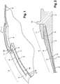
- the figure 1 shows the top of a tank according to an example not forming part of the invention comprising a tank body 1, a liner 2 and a composite body 3 wound on the liner.
- the tank is generally cylindrical with rounded ends, at least one of the ends comprising a base 4.
- the base 4 at the top of the reservoir serves for example to receive the reservoir connection means for filling or emptying it.
- the composite body is produced by winding composite fibers such as for example carbon fibers impregnated with resin and the composite body is wound on the liner and glued (19) on the liner.
- the liner 2 and the composite body 3 are glued to one another on the cylindrical part 19 and on a part of the curved surface forming the dome of the tank comprising the base but are not glued on an annular region 5 of junction between the reservoir body and the base, this annular region surrounding the base.
- the annular region is more particularly represented on the figure 2 sectional view of the top of the tank, this annular region 5 extending towards the base above a collar 7 of the base or base collar which designates the peripheral end of the base, a collar called the wing base in the language of the field of the invention and the coiled composite body extending over the collar without being secured to the collar.
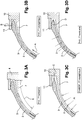
- annular region for which the composite body is detached from the liner and from the flange 7 of the base 4 is more particularly shown in figures 3A to 3D depending on the conditions of use of the tank.
- the figure 3A represents the upper part of the reservoir comprising the annular region in section in a situation of rest, zero pressure and ambient temperature.
- a layer 13 of material with a low coefficient of friction or non-stick is placed between the liner and the composite body and between the flange and the composite body.
- This material with a high coefficient of friction is for example PTFE tape deposited all around the base and on the end part of the liner by helical deposition once the liner and the flange are connected together by welding or gluing at their junction line. 6.
- the composite body ends at the level of the base with a bead 9 resting on the collar 7 and retained by the flange 11.
- the flange 11 for retaining the bead is mounted on a central cylindrical neck 10 of the base.
- An annular seal 12 is disposed between the flange and the bead so that the flange presses moderately on the bead to maintain it in a vertical direction parallel to the axis of symmetry of the base.
- the neck of the base and the flange can be provided with complementary threads in order to mount the flange by screwing and thus adjust the support of the flange on the bead.
- the flange can also be glued at 14 on the neck of the base.
- the flange or base wing 7 is of decreasing thickness towards its periphery.
- Pure aluminum in the annealed state (1050-O or 1100-O or 1050H111) is the preferred candidate for this liner, including in the cryogenic case.
- aluminum alloys are designated using a numerical system of four digits which identify the chemical composition of the alloy.
- the 1000 series means at least 99% aluminum.
- the second number indicates a variant of the initial alloy. Often this is a smaller range in one or more elements of the alloy.
- the third and fourth digits indicate, for the 1000 series, the minimum aluminum percentage, for example 1050 indicating at least 99.50% aluminum.
- Aluminum alloy parts obtained by deformation are classified as metallurgical. There are five standardized states, classified by a letter.
- the letter “O” means “annealed”.
- the letter "H", which means "hardened”, is followed by two or three digits.
- the first number indicates the type of thermomechanical range.
- the second figure gives the degree of hardening and therefore the degree of mechanical characteristic.
- the possible third digit indicates a variant.
- An example of application of the invention is a cryogenic tank with a diameter of 1600mm with a 1050-O aluminum liner with a thickness of 1mm.
- the capacity is achieved to have an operating pressure of 40 bars and a burst pressure of 80 bars.
- top of the capacity according to the example is represented in figure 4 .
- a shutter 15 closes the end piece 4 and is attached to this seemingly end piece a connection zone 16.
- the flange 11 fixed to the neck of the base 10 rests on the bead 9 of the coiled body via an interposition material 12 intended not to injure the composite.
- the wound body covers the flange of the base and the upper part of the liner without being glued to it.
- a possible material 13 with a low coefficient of friction is interposed between the coiled body and the flange / wing assembly and the upper part of the liner.
- the radius of the base at the neck of the base is of the order of 196 mm
- the flange extends beyond the base for approximately 100 to 120 mm
- the non-glued area extends to at a distance to the axis of revolution Z of the capacitor such that the radius of the capacitor is R500 at 510 mm at this point.
- the thickness of the liner is kept constant in the non-glued area to minimize the strain peak. Any variations in thickness are localized in the area where the liner is glued to the capacity. According to this example, the liner has a thickness e1 of 1.4 mm in the non-glued zone and e2 of 1 mm on the rest of the tank, which gives a hold compatible with the desired application.
- the liner is made of a material with high elastic limit, for example an aluminum alloy 2219-T87 which means that the element of The main alloy is Copper and that the main phase present in the alloy is Al 2 Cu - Al 2 CuMg, T signifying that this alloy has undergone a heat treatment.
- an aluminum alloy 2219-T87 which means that the element of The main alloy is Copper and that the main phase present in the alloy is Al 2 Cu - Al 2 CuMg, T signifying that this alloy has undergone a heat treatment.
- the functions of the flange 11 are in particular to prevent the introduction of forces on the liner and the bonded connection during the non-pressurized phases, during the manufacture and / or the integration of the capacity, to keep the base integral with the bead during cooling and allow movement of the bead under the action of internal pressure.
- the figure 6 represents the result of the calculation in terms of the cumulated plastic deformation of the liner along the Z axis starting from the origin towards the base zone for the positive abscissas.
- the zero point of the abscissa is the plane where the cylindrical part of the tank meets the bottom (where the bottom begins) and this point is called the “bottom reference”.
- the negative abscissas correspond to the cylindrical part of the tank, the positive to the bottom.
- Point 24 of the figure 6 is the gluing stop zone. It appears close to point 25 because the graph shows the axial abscissas.
- the solution of the invention makes it possible to dispense with the elastomeric solutions of the state of the art which are not applicable in the case of cryogenic tanks.
- the materials for making the wound composite body are, for example, intermediate modulus carbon fiber type T800 from the company Toray (registered trademark) or IM7 from the Hexel company (registered trademark), many variations being possible.
- thermosetting epoxy resin B413 M15 from ASTRIUM or thermoplastic resin type PA12 generic chemical name of a polyamide.
- the bonding of the composite body and the liner is carried out with an epoxy adhesive from the company Hysol (registered trademark) EA9321.
- the figure 5 corresponds to a variant of the invention for which the liner is made in two parts 2, 2 'glued at 17, the second part forming an annular segment connecting the first part of the liner to the flange 7 of the base 4.
- the composite body is glued to the first part of the liner and the gluing of the composite body extends over the second part 2 'of the liner in a zone of overlap of the two parts of the liner.
- the composite body covers the second part 2 'of the liner and the collar 7 of the base without being glued thereto.
- This embodiment makes it possible to produce an extra thickness of the liner in the second part 2 ′ to increase the mechanical resistance of the reservoir.
- a step of assembling a liner 2 with a base 4 is carried out, then a composite body 3 is wound up on the liner and a step of bonding the liner 2 and the composite body 3 is carried out. on the other with the exception of an annular junction region 5, between the tank body and the base, surrounding the base.
- a material with a low coefficient of friction is applied to said annular junction region 5, between the tank body and the base, surrounding the base before winding the composite body and gluing the liner and the composite body.
Landscapes
- Engineering & Computer Science (AREA)
- Mechanical Engineering (AREA)
- General Engineering & Computer Science (AREA)
- Filling Or Discharging Of Gas Storage Vessels (AREA)
Applications Claiming Priority (2)
| Application Number | Priority Date | Filing Date | Title |
|---|---|---|---|
| FR1056418A FR2963659B1 (fr) | 2010-08-03 | 2010-08-03 | Liaison entre liner metallique et structure composite dans la zone d'embase d'un reservoir |
| PCT/EP2011/063238 WO2012016956A1 (fr) | 2010-08-03 | 2011-08-01 | Liaison entre liner métallique et structure composite dans la zone d'embase d'un réservoir |
Publications (2)
| Publication Number | Publication Date |
|---|---|
| EP2601434A1 EP2601434A1 (fr) | 2013-06-12 |
| EP2601434B1 true EP2601434B1 (fr) | 2020-09-30 |
Family
ID=43014577
Family Applications (1)
| Application Number | Title | Priority Date | Filing Date |
|---|---|---|---|
| EP11737977.6A Active EP2601434B1 (fr) | 2010-08-03 | 2011-08-01 | Liaison entre liner métallique et structure composite dans la zone d'embase d'un réservoir |
Country Status (5)
| Country | Link |
|---|---|
| US (1) | US20130186893A1 (enExample) |
| EP (1) | EP2601434B1 (enExample) |
| JP (1) | JP5948330B2 (enExample) |
| FR (1) | FR2963659B1 (enExample) |
| WO (1) | WO2012016956A1 (enExample) |
Families Citing this family (6)
| Publication number | Priority date | Publication date | Assignee | Title |
|---|---|---|---|---|
| FR3004141B1 (fr) * | 2013-04-03 | 2015-05-15 | Astrium Sas | Liaison entre un liner metallique mince et une paroi en composite par enduction chargee de particules thermoplastiques |
| JP5999039B2 (ja) | 2013-07-10 | 2016-09-28 | トヨタ自動車株式会社 | 高圧タンクおよび高圧タンクの製造方法 |
| EP3556688B1 (en) * | 2017-03-22 | 2023-03-01 | IHI Corporation | Low-temperature tank and method for manufacturing same |
| JP7066995B2 (ja) * | 2017-08-10 | 2022-05-16 | トヨタ自動車株式会社 | 高圧容器 |
| JP7014060B2 (ja) * | 2018-06-21 | 2022-02-01 | トヨタ自動車株式会社 | 高圧タンク、高圧タンク搭載装置、および高圧タンクの製造方法 |
| KR102309641B1 (ko) * | 2020-03-02 | 2021-10-07 | 주식회사 엔케이 | 복합재 용기 및 이의 제조방법 |
Family Cites Families (44)
| Publication number | Priority date | Publication date | Assignee | Title |
|---|---|---|---|---|
| US3073475A (en) * | 1959-10-30 | 1963-01-15 | Minnesota Mining & Mfg | Pressure vessel and method of making the same |
| US3057509A (en) * | 1960-02-11 | 1962-10-09 | Brunswick Corp | Pressure vessel bladder |
| US3321347A (en) * | 1964-08-10 | 1967-05-23 | Douglas Aircraft Co Inc | Method of making a metallic-lined pressure vessel |
| US3815773A (en) * | 1971-05-17 | 1974-06-11 | Brunswick Corp | Cyclic pressure vessel |
| US3843010A (en) * | 1971-10-13 | 1974-10-22 | Brunswick Corp | Metal lined pressure vessel |
| US3969812A (en) * | 1974-04-19 | 1976-07-20 | Martin Marietta Corporation | Method of manufacturing an overwrapped pressure vessel |
| US4053081A (en) * | 1976-08-20 | 1977-10-11 | The United States Of America As Represented By The Secretary Of The Navy | Reinforced filament-wound cut-port pressure vessel and method of making same |
| US4360116A (en) * | 1980-12-08 | 1982-11-23 | Brunswick Corporation | Partially split external barrier for composite structures |
| US4614279A (en) * | 1984-12-13 | 1986-09-30 | Essef Industries, Inc. | Side tap opening for a filament-wound tank |
| SE452284B (sv) * | 1986-03-10 | 1987-11-23 | Saab Composite Ab | Tryckkerl av kompositmaterial med i lindningen infogade gavelstycken |
| CA1326832C (fr) * | 1987-07-21 | 1994-02-08 | Claude Leon Hembert | Reservoir de fluide et son procede de fabrication |
| FR2647183B1 (fr) * | 1989-05-18 | 1991-07-26 | Hembert Claude | Dispositif pour proteger les extremites de reservoir de fluide en materiaux composites |
| FR2669396B1 (fr) * | 1990-11-19 | 1997-05-09 | Inst Francais Du Petrole | Reservoir de poids unitaire faible utilisable notamment pour le stockage de fluides sous pression et son procede de fabrication. |
| US5429845A (en) * | 1992-01-10 | 1995-07-04 | Brunswick Corporation | Boss for a filament wound pressure vessel |
| US5494188A (en) * | 1992-01-28 | 1996-02-27 | Edo Canada Ltd. | Fluid pressure vessel boss-liner attachment system with liner/exterior mechanism direct coupling |
| US5287988A (en) | 1993-02-03 | 1994-02-22 | Brunswick Corporation | Metal-lined pressure vessel |
| US5407092A (en) * | 1993-09-08 | 1995-04-18 | Trw Inc. | Profiled thickness bonded rolling diaphragm tank |
| US5419139A (en) * | 1993-12-13 | 1995-05-30 | Martin Marietta Corporation | Composite cryogenic tank apparatus |
| US5518141A (en) * | 1994-01-24 | 1996-05-21 | Newhouse; Norman L. | Pressure vessel with system to prevent liner separation |
| US5653358A (en) * | 1994-04-08 | 1997-08-05 | Arde, Inc. | Multilayer composite pressure vessel with a fitting incorporated in a stem portion thereof |
| US5568878A (en) * | 1996-01-11 | 1996-10-29 | Essef Corporation | Filament wound pressure vessel having a reinforced access opening |
| US5822838A (en) * | 1996-02-01 | 1998-10-20 | Lockheed Martin Corporation | High performance, thin metal lined, composite overwrapped pressure vessel |
| US5938209A (en) * | 1997-02-14 | 1999-08-17 | Alternative Fuel Systems, Inc. | Seal system for fluid pressure vessels |
| JPH10332083A (ja) * | 1997-05-28 | 1998-12-15 | Mitsubishi Chem Corp | 耐圧容器 |
| DE19751411C1 (de) * | 1997-11-14 | 1999-01-14 | Mannesmann Ag | Composite-Druckbehälter zur Speicherung von gasförmigen Medien unter Druck mit einem Liner aus Kunststoff |
| US5979692A (en) * | 1998-03-13 | 1999-11-09 | Harsco Corporation | Boss for composite pressure vessel having polymeric liner |
| US6135308A (en) * | 1998-06-26 | 2000-10-24 | Industrial Technology Research Institute | Boss for a filament wound pressure vessel |
| JP3523802B2 (ja) * | 1999-04-07 | 2004-04-26 | 豊田合成株式会社 | 圧力容器 |
| NL1014290C2 (nl) * | 2000-02-04 | 2001-08-07 | Advanced Lightweight Const Gro | Vezelversterkt drukvat en werkwijze voor het maken van een vezelversterkt drukvat. |
| US6547092B1 (en) * | 2000-11-14 | 2003-04-15 | Solomon Chervatsky | Pressure vessel with thin unstressed metallic liner |
| FR2824892B1 (fr) * | 2001-05-18 | 2003-08-29 | Eads Launch Vehicles | Procede de fabrication d'un reservoir haute pression notamment pour lanceur spatial et reservoir obtenu |
| US7147124B2 (en) * | 2002-03-27 | 2006-12-12 | Exxon Mobil Upstream Research Company | Containers and methods for containing pressurized fluids using reinforced fibers and methods for making such containers |
| US7803241B2 (en) * | 2002-04-12 | 2010-09-28 | Microcosm, Inc. | Composite pressure tank and process for its manufacture |
| KR100469636B1 (ko) * | 2004-03-11 | 2005-02-02 | 주식회사 케이시알 | 복합재료 고압용기용 고밀폐도 금속성 노즐보스 |
| US7731051B2 (en) * | 2005-07-13 | 2010-06-08 | Gm Global Technology Operations, Inc. | Hydrogen pressure tank including an inner liner with an outer annular flange |
| DE102006004121A1 (de) * | 2006-01-25 | 2007-07-26 | Hydac Technology Gmbh | Druckbehälter |
| JP4457359B2 (ja) * | 2006-12-13 | 2010-04-28 | トヨタ自動車株式会社 | 圧力容器 |
| US7867589B2 (en) * | 2007-07-20 | 2011-01-11 | The United States Of America As Represented By The Administrator Of The National Aeronautics And Space Administration | Hybrid cryogenic tank construction and method of manufacture therefor |
| RU2393375C2 (ru) * | 2008-08-27 | 2010-06-27 | Сергей Владимирович ЛУКЬЯНЕЦ | Баллон высокого давления |
| KR101434013B1 (ko) * | 2009-02-18 | 2014-08-25 | 헥사곤 테크놀로지 에이에스 | 압력 용기 보스와 쉘을 위한 내전단성 인터페이스 요소 |
| WO2010116528A1 (ja) * | 2009-04-10 | 2010-10-14 | トヨタ自動車株式会社 | タンクおよびその製造方法 |
| WO2010116526A1 (ja) * | 2009-04-10 | 2010-10-14 | トヨタ自動車株式会社 | タンクおよびその製造方法 |
| US8517206B2 (en) * | 2009-05-19 | 2013-08-27 | Quantum Fuel Systems Technologies Worldwide Inc. | High pressure storage vessel |
| US8733581B1 (en) * | 2012-07-16 | 2014-05-27 | Michael A. Olson | Boss seal for composite overwrapped pressure vessel |
-
2010
- 2010-08-03 FR FR1056418A patent/FR2963659B1/fr active Active
-
2011
- 2011-08-01 EP EP11737977.6A patent/EP2601434B1/fr active Active
- 2011-08-01 US US13/813,541 patent/US20130186893A1/en not_active Abandoned
- 2011-08-01 WO PCT/EP2011/063238 patent/WO2012016956A1/fr not_active Ceased
- 2011-08-01 JP JP2013522223A patent/JP5948330B2/ja active Active
Non-Patent Citations (1)
| Title |
|---|
| None * |
Also Published As
| Publication number | Publication date |
|---|---|
| EP2601434A1 (fr) | 2013-06-12 |
| US20130186893A1 (en) | 2013-07-25 |
| FR2963659A1 (fr) | 2012-02-10 |
| WO2012016956A1 (fr) | 2012-02-09 |
| JP5948330B2 (ja) | 2016-07-06 |
| JP2013535632A (ja) | 2013-09-12 |
| FR2963659B1 (fr) | 2014-03-21 |
Similar Documents
| Publication | Publication Date | Title |
|---|---|---|
| EP2601434B1 (fr) | Liaison entre liner métallique et structure composite dans la zone d'embase d'un réservoir | |
| CN113280253B (zh) | 高压罐的制造方法 | |
| EP3077178B1 (fr) | Procédé de collage de pièces et dispositif pour la mise en oeuvre de ce procédé | |
| EP0300931A1 (fr) | Réservoir de fluide et son procédé de fabrication | |
| CN113108235B (zh) | 高压罐的制造方法 | |
| CN113280254A (zh) | 高压罐 | |
| WO2015162388A1 (fr) | Procédé de fabrication d'une roue dentée allégée par surmoulage double | |
| US8091203B2 (en) | High pressure tank and method thereof | |
| EP0067919A1 (fr) | Tuyau en matière plastique renforcé par une armature | |
| FR2947609A1 (fr) | Dispositif de raccordement pour canalisations et procede de raccordement associe | |
| EP3152027B1 (fr) | Procédé de fabrication de roue dentée avec cerclage de renfort | |
| EP3302916B1 (fr) | Profilé creux tel qu'un tube réalisé en matériaux composite thermodurcissable et son procédé | |
| EP2981405B1 (fr) | Liaison entre un liner métallique mince et une paroi en composite par enduction chargée de particules thermoplastiques | |
| WO2019193273A1 (fr) | Assemblage d'étanchéité métallique pour l'étanchéité entre un arbre tournant et un bâti fixe | |
| EP0098766A1 (fr) | Récipient à forte isolation thermique et son procédé de fabrication | |
| WO2015158983A1 (fr) | Assemblage riveté et procédé de fabrication associé | |
| FR2671158A1 (fr) | Raidisseur renforce et son procede de realisation. | |
| JP2008101677A (ja) | 高圧ガス容器 | |
| EP1473503B1 (fr) | Conduit souple à ondulations équipé d'au moins un anneau métallique de maintien et son procédé de fabrication. | |
| EP4061610B1 (fr) | Procédé de fabrication d'un réservoir composite de fluide sous pression | |
| CH704686A1 (fr) | Ressort horloger pour montre-bracelet. | |
| WO2018229049A1 (fr) | Conduit pour réservoir à carburant de véhicule convenant pour la soudure | |
| FR2948166A1 (fr) | Reservoir de fluide sous pression et son procede de fabrication | |
| FR3116313A1 (fr) | Ressort élastique à spires, système d’amortissement et procédé de fabrication associés | |
| WO2015193135A1 (fr) | Vanne motorisée et procédure d'assemblage d'un moyen de fixation |
Legal Events
| Date | Code | Title | Description |
|---|---|---|---|
| PUAI | Public reference made under article 153(3) epc to a published international application that has entered the european phase |
Free format text: ORIGINAL CODE: 0009012 |
|
| 17P | Request for examination filed |
Effective date: 20130212 |
|
| AK | Designated contracting states |
Kind code of ref document: A1 Designated state(s): AL AT BE BG CH CY CZ DE DK EE ES FI FR GB GR HR HU IE IS IT LI LT LU LV MC MK MT NL NO PL PT RO RS SE SI SK SM TR |
|
| DAX | Request for extension of the european patent (deleted) | ||
| 17Q | First examination report despatched |
Effective date: 20131121 |
|
| RAP1 | Party data changed (applicant data changed or rights of an application transferred) |
Owner name: AIRBUS DEFENCE AND SPACE SAS |
|
| RAP1 | Party data changed (applicant data changed or rights of an application transferred) |
Owner name: ARIANEGROUP SAS |
|
| GRAP | Despatch of communication of intention to grant a patent |
Free format text: ORIGINAL CODE: EPIDOSNIGR1 |
|
| STAA | Information on the status of an ep patent application or granted ep patent |
Free format text: STATUS: GRANT OF PATENT IS INTENDED |
|
| INTG | Intention to grant announced |
Effective date: 20200311 |
|
| RIN1 | Information on inventor provided before grant (corrected) |
Inventor name: CLAUDEL, SYLVAIN |
|
| GRAS | Grant fee paid |
Free format text: ORIGINAL CODE: EPIDOSNIGR3 |
|
| GRAA | (expected) grant |
Free format text: ORIGINAL CODE: 0009210 |
|
| STAA | Information on the status of an ep patent application or granted ep patent |
Free format text: STATUS: THE PATENT HAS BEEN GRANTED |
|
| AK | Designated contracting states |
Kind code of ref document: B1 Designated state(s): AL AT BE BG CH CY CZ DE DK EE ES FI FR GB GR HR HU IE IS IT LI LT LU LV MC MK MT NL NO PL PT RO RS SE SI SK SM TR |
|
| REG | Reference to a national code |
Ref country code: CH Ref legal event code: EP Ref country code: GB Ref legal event code: FG4D Free format text: NOT ENGLISH |
|
| REG | Reference to a national code |
Ref country code: DE Ref legal event code: R096 Ref document number: 602011068770 Country of ref document: DE Ref country code: AT Ref legal event code: REF Ref document number: 1319144 Country of ref document: AT Kind code of ref document: T Effective date: 20201015 |
|
| REG | Reference to a national code |
Ref country code: IE Ref legal event code: FG4D Free format text: LANGUAGE OF EP DOCUMENT: FRENCH |
|
| PG25 | Lapsed in a contracting state [announced via postgrant information from national office to epo] |
Ref country code: SE Free format text: LAPSE BECAUSE OF FAILURE TO SUBMIT A TRANSLATION OF THE DESCRIPTION OR TO PAY THE FEE WITHIN THE PRESCRIBED TIME-LIMIT Effective date: 20200930 Ref country code: NO Free format text: LAPSE BECAUSE OF FAILURE TO SUBMIT A TRANSLATION OF THE DESCRIPTION OR TO PAY THE FEE WITHIN THE PRESCRIBED TIME-LIMIT Effective date: 20201230 Ref country code: BG Free format text: LAPSE BECAUSE OF FAILURE TO SUBMIT A TRANSLATION OF THE DESCRIPTION OR TO PAY THE FEE WITHIN THE PRESCRIBED TIME-LIMIT Effective date: 20201230 Ref country code: HR Free format text: LAPSE BECAUSE OF FAILURE TO SUBMIT A TRANSLATION OF THE DESCRIPTION OR TO PAY THE FEE WITHIN THE PRESCRIBED TIME-LIMIT Effective date: 20200930 Ref country code: FI Free format text: LAPSE BECAUSE OF FAILURE TO SUBMIT A TRANSLATION OF THE DESCRIPTION OR TO PAY THE FEE WITHIN THE PRESCRIBED TIME-LIMIT Effective date: 20200930 Ref country code: GR Free format text: LAPSE BECAUSE OF FAILURE TO SUBMIT A TRANSLATION OF THE DESCRIPTION OR TO PAY THE FEE WITHIN THE PRESCRIBED TIME-LIMIT Effective date: 20201231 |
|
| REG | Reference to a national code |
Ref country code: AT Ref legal event code: MK05 Ref document number: 1319144 Country of ref document: AT Kind code of ref document: T Effective date: 20200930 |
|
| PG25 | Lapsed in a contracting state [announced via postgrant information from national office to epo] |
Ref country code: LV Free format text: LAPSE BECAUSE OF FAILURE TO SUBMIT A TRANSLATION OF THE DESCRIPTION OR TO PAY THE FEE WITHIN THE PRESCRIBED TIME-LIMIT Effective date: 20200930 Ref country code: RS Free format text: LAPSE BECAUSE OF FAILURE TO SUBMIT A TRANSLATION OF THE DESCRIPTION OR TO PAY THE FEE WITHIN THE PRESCRIBED TIME-LIMIT Effective date: 20200930 |
|
| REG | Reference to a national code |
Ref country code: NL Ref legal event code: MP Effective date: 20200930 |
|
| REG | Reference to a national code |
Ref country code: LT Ref legal event code: MG4D |
|
| PG25 | Lapsed in a contracting state [announced via postgrant information from national office to epo] |
Ref country code: SM Free format text: LAPSE BECAUSE OF FAILURE TO SUBMIT A TRANSLATION OF THE DESCRIPTION OR TO PAY THE FEE WITHIN THE PRESCRIBED TIME-LIMIT Effective date: 20200930 Ref country code: RO Free format text: LAPSE BECAUSE OF FAILURE TO SUBMIT A TRANSLATION OF THE DESCRIPTION OR TO PAY THE FEE WITHIN THE PRESCRIBED TIME-LIMIT Effective date: 20200930 Ref country code: PT Free format text: LAPSE BECAUSE OF FAILURE TO SUBMIT A TRANSLATION OF THE DESCRIPTION OR TO PAY THE FEE WITHIN THE PRESCRIBED TIME-LIMIT Effective date: 20210201 Ref country code: LT Free format text: LAPSE BECAUSE OF FAILURE TO SUBMIT A TRANSLATION OF THE DESCRIPTION OR TO PAY THE FEE WITHIN THE PRESCRIBED TIME-LIMIT Effective date: 20200930 Ref country code: NL Free format text: LAPSE BECAUSE OF FAILURE TO SUBMIT A TRANSLATION OF THE DESCRIPTION OR TO PAY THE FEE WITHIN THE PRESCRIBED TIME-LIMIT Effective date: 20200930 Ref country code: CZ Free format text: LAPSE BECAUSE OF FAILURE TO SUBMIT A TRANSLATION OF THE DESCRIPTION OR TO PAY THE FEE WITHIN THE PRESCRIBED TIME-LIMIT Effective date: 20200930 Ref country code: EE Free format text: LAPSE BECAUSE OF FAILURE TO SUBMIT A TRANSLATION OF THE DESCRIPTION OR TO PAY THE FEE WITHIN THE PRESCRIBED TIME-LIMIT Effective date: 20200930 |
|
| PG25 | Lapsed in a contracting state [announced via postgrant information from national office to epo] |
Ref country code: PL Free format text: LAPSE BECAUSE OF FAILURE TO SUBMIT A TRANSLATION OF THE DESCRIPTION OR TO PAY THE FEE WITHIN THE PRESCRIBED TIME-LIMIT Effective date: 20200930 Ref country code: AT Free format text: LAPSE BECAUSE OF FAILURE TO SUBMIT A TRANSLATION OF THE DESCRIPTION OR TO PAY THE FEE WITHIN THE PRESCRIBED TIME-LIMIT Effective date: 20200930 Ref country code: AL Free format text: LAPSE BECAUSE OF FAILURE TO SUBMIT A TRANSLATION OF THE DESCRIPTION OR TO PAY THE FEE WITHIN THE PRESCRIBED TIME-LIMIT Effective date: 20200930 Ref country code: IS Free format text: LAPSE BECAUSE OF FAILURE TO SUBMIT A TRANSLATION OF THE DESCRIPTION OR TO PAY THE FEE WITHIN THE PRESCRIBED TIME-LIMIT Effective date: 20210130 Ref country code: ES Free format text: LAPSE BECAUSE OF FAILURE TO SUBMIT A TRANSLATION OF THE DESCRIPTION OR TO PAY THE FEE WITHIN THE PRESCRIBED TIME-LIMIT Effective date: 20200930 |
|
| PG25 | Lapsed in a contracting state [announced via postgrant information from national office to epo] |
Ref country code: SK Free format text: LAPSE BECAUSE OF FAILURE TO SUBMIT A TRANSLATION OF THE DESCRIPTION OR TO PAY THE FEE WITHIN THE PRESCRIBED TIME-LIMIT Effective date: 20200930 |
|
| REG | Reference to a national code |
Ref country code: DE Ref legal event code: R097 Ref document number: 602011068770 Country of ref document: DE |
|
| PLBE | No opposition filed within time limit |
Free format text: ORIGINAL CODE: 0009261 |
|
| STAA | Information on the status of an ep patent application or granted ep patent |
Free format text: STATUS: NO OPPOSITION FILED WITHIN TIME LIMIT |
|
| PG25 | Lapsed in a contracting state [announced via postgrant information from national office to epo] |
Ref country code: DK Free format text: LAPSE BECAUSE OF FAILURE TO SUBMIT A TRANSLATION OF THE DESCRIPTION OR TO PAY THE FEE WITHIN THE PRESCRIBED TIME-LIMIT Effective date: 20200930 |
|
| 26N | No opposition filed |
Effective date: 20210701 |
|
| PG25 | Lapsed in a contracting state [announced via postgrant information from national office to epo] |
Ref country code: SI Free format text: LAPSE BECAUSE OF FAILURE TO SUBMIT A TRANSLATION OF THE DESCRIPTION OR TO PAY THE FEE WITHIN THE PRESCRIBED TIME-LIMIT Effective date: 20200930 |
|
| REG | Reference to a national code |
Ref country code: CH Ref legal event code: PL |
|
| PG25 | Lapsed in a contracting state [announced via postgrant information from national office to epo] |
Ref country code: MC Free format text: LAPSE BECAUSE OF FAILURE TO SUBMIT A TRANSLATION OF THE DESCRIPTION OR TO PAY THE FEE WITHIN THE PRESCRIBED TIME-LIMIT Effective date: 20200930 |
|
| REG | Reference to a national code |
Ref country code: BE Ref legal event code: MM Effective date: 20210831 |
|
| PG25 | Lapsed in a contracting state [announced via postgrant information from national office to epo] |
Ref country code: LI Free format text: LAPSE BECAUSE OF NON-PAYMENT OF DUE FEES Effective date: 20210831 Ref country code: CH Free format text: LAPSE BECAUSE OF NON-PAYMENT OF DUE FEES Effective date: 20210831 |
|
| PG25 | Lapsed in a contracting state [announced via postgrant information from national office to epo] |
Ref country code: IS Free format text: LAPSE BECAUSE OF FAILURE TO SUBMIT A TRANSLATION OF THE DESCRIPTION OR TO PAY THE FEE WITHIN THE PRESCRIBED TIME-LIMIT Effective date: 20210130 Ref country code: LU Free format text: LAPSE BECAUSE OF NON-PAYMENT OF DUE FEES Effective date: 20210801 |
|
| PG25 | Lapsed in a contracting state [announced via postgrant information from national office to epo] |
Ref country code: IE Free format text: LAPSE BECAUSE OF NON-PAYMENT OF DUE FEES Effective date: 20210801 Ref country code: BE Free format text: LAPSE BECAUSE OF NON-PAYMENT OF DUE FEES Effective date: 20210831 |
|
| PG25 | Lapsed in a contracting state [announced via postgrant information from national office to epo] |
Ref country code: HU Free format text: LAPSE BECAUSE OF FAILURE TO SUBMIT A TRANSLATION OF THE DESCRIPTION OR TO PAY THE FEE WITHIN THE PRESCRIBED TIME-LIMIT; INVALID AB INITIO Effective date: 20110801 Ref country code: CY Free format text: LAPSE BECAUSE OF FAILURE TO SUBMIT A TRANSLATION OF THE DESCRIPTION OR TO PAY THE FEE WITHIN THE PRESCRIBED TIME-LIMIT Effective date: 20200930 |
|
| P01 | Opt-out of the competence of the unified patent court (upc) registered |
Effective date: 20230612 |
|
| REG | Reference to a national code |
Ref country code: DE Ref legal event code: R082 Ref document number: 602011068770 Country of ref document: DE Representative=s name: KANDLBINDER, MARKUS, DIPL.-PHYS., DE |
|
| PG25 | Lapsed in a contracting state [announced via postgrant information from national office to epo] |
Ref country code: MK Free format text: LAPSE BECAUSE OF FAILURE TO SUBMIT A TRANSLATION OF THE DESCRIPTION OR TO PAY THE FEE WITHIN THE PRESCRIBED TIME-LIMIT Effective date: 20200930 |
|
| PG25 | Lapsed in a contracting state [announced via postgrant information from national office to epo] |
Ref country code: MT Free format text: LAPSE BECAUSE OF FAILURE TO SUBMIT A TRANSLATION OF THE DESCRIPTION OR TO PAY THE FEE WITHIN THE PRESCRIBED TIME-LIMIT Effective date: 20200930 |
|
| PGFP | Annual fee paid to national office [announced via postgrant information from national office to epo] |
Ref country code: DE Payment date: 20250820 Year of fee payment: 15 |
|
| PGFP | Annual fee paid to national office [announced via postgrant information from national office to epo] |
Ref country code: IT Payment date: 20250825 Year of fee payment: 15 |
|
| PGFP | Annual fee paid to national office [announced via postgrant information from national office to epo] |
Ref country code: GB Payment date: 20250820 Year of fee payment: 15 |
|
| PGFP | Annual fee paid to national office [announced via postgrant information from national office to epo] |
Ref country code: FR Payment date: 20250829 Year of fee payment: 15 |
|
| PG25 | Lapsed in a contracting state [announced via postgrant information from national office to epo] |
Ref country code: TR Free format text: LAPSE BECAUSE OF FAILURE TO SUBMIT A TRANSLATION OF THE DESCRIPTION OR TO PAY THE FEE WITHIN THE PRESCRIBED TIME-LIMIT Effective date: 20200930 |