EP3556688B1 - Low-temperature tank and method for manufacturing same - Google Patents
Low-temperature tank and method for manufacturing same Download PDFInfo
- Publication number
- EP3556688B1 EP3556688B1 EP17901669.6A EP17901669A EP3556688B1 EP 3556688 B1 EP3556688 B1 EP 3556688B1 EP 17901669 A EP17901669 A EP 17901669A EP 3556688 B1 EP3556688 B1 EP 3556688B1
- Authority
- EP
- European Patent Office
- Prior art keywords
- wall member
- metal liner
- low
- temperature tank
- filler
- Prior art date
- Legal status (The legal status is an assumption and is not a legal conclusion. Google has not performed a legal analysis and makes no representation as to the accuracy of the status listed.)
- Active
Links
- 238000004519 manufacturing process Methods 0.000 title claims description 18
- 238000000034 method Methods 0.000 title claims description 15
- 229910052751 metal Inorganic materials 0.000 claims description 79
- 239000002184 metal Substances 0.000 claims description 79
- 239000000945 filler Substances 0.000 claims description 24
- 238000005245 sintering Methods 0.000 claims description 15
- 238000003860 storage Methods 0.000 claims description 13
- 230000002093 peripheral effect Effects 0.000 claims description 12
- 238000004804 winding Methods 0.000 claims description 10
- 229920002430 Fibre-reinforced plastic Polymers 0.000 claims description 9
- 239000011151 fibre-reinforced plastic Substances 0.000 claims description 9
- 239000000463 material Substances 0.000 claims description 8
- 239000002131 composite material Substances 0.000 description 23
- 238000010586 diagram Methods 0.000 description 15
- 239000007788 liquid Substances 0.000 description 13
- 230000008602 contraction Effects 0.000 description 11
- 239000011159 matrix material Substances 0.000 description 11
- 238000012986 modification Methods 0.000 description 9
- 230000004048 modification Effects 0.000 description 9
- 239000004918 carbon fiber reinforced polymer Substances 0.000 description 5
- 239000000470 constituent Substances 0.000 description 5
- 239000000835 fiber Substances 0.000 description 5
- 238000005304 joining Methods 0.000 description 5
- 239000007789 gas Substances 0.000 description 3
- IJGRMHOSHXDMSA-UHFFFAOYSA-N Atomic nitrogen Chemical compound N#N IJGRMHOSHXDMSA-UHFFFAOYSA-N 0.000 description 2
- 239000000446 fuel Substances 0.000 description 2
- 238000012423 maintenance Methods 0.000 description 2
- 239000012528 membrane Substances 0.000 description 2
- VNWKTOKETHGBQD-UHFFFAOYSA-N methane Chemical compound C VNWKTOKETHGBQD-UHFFFAOYSA-N 0.000 description 2
- 239000003380 propellant Substances 0.000 description 2
- 239000011347 resin Substances 0.000 description 2
- 229920005989 resin Polymers 0.000 description 2
- 238000003466 welding Methods 0.000 description 2
- 229920000049 Carbon (fiber) Polymers 0.000 description 1
- MYMOFIZGZYHOMD-UHFFFAOYSA-N Dioxygen Chemical compound O=O MYMOFIZGZYHOMD-UHFFFAOYSA-N 0.000 description 1
- FYYHWMGAXLPEAU-UHFFFAOYSA-N Magnesium Chemical compound [Mg] FYYHWMGAXLPEAU-UHFFFAOYSA-N 0.000 description 1
- 239000000853 adhesive Substances 0.000 description 1
- 230000001070 adhesive effect Effects 0.000 description 1
- 229910045601 alloy Inorganic materials 0.000 description 1
- 239000000956 alloy Substances 0.000 description 1
- 229910052782 aluminium Inorganic materials 0.000 description 1
- XAGFODPZIPBFFR-UHFFFAOYSA-N aluminium Chemical compound [Al] XAGFODPZIPBFFR-UHFFFAOYSA-N 0.000 description 1
- 229920006231 aramid fiber Polymers 0.000 description 1
- 238000005422 blasting Methods 0.000 description 1
- 239000004917 carbon fiber Substances 0.000 description 1
- 238000001816 cooling Methods 0.000 description 1
- 230000000694 effects Effects 0.000 description 1
- 238000001704 evaporation Methods 0.000 description 1
- 230000008020 evaporation Effects 0.000 description 1
- 229920006248 expandable polystyrene Polymers 0.000 description 1
- 229920002313 fluoropolymer Polymers 0.000 description 1
- 238000010438 heat treatment Methods 0.000 description 1
- 239000001307 helium Substances 0.000 description 1
- 229910052734 helium Inorganic materials 0.000 description 1
- SWQJXJOGLNCZEY-UHFFFAOYSA-N helium atom Chemical compound [He] SWQJXJOGLNCZEY-UHFFFAOYSA-N 0.000 description 1
- 239000001257 hydrogen Substances 0.000 description 1
- 229910052739 hydrogen Inorganic materials 0.000 description 1
- 125000004435 hydrogen atom Chemical class [H]* 0.000 description 1
- 238000002347 injection Methods 0.000 description 1
- 239000007924 injection Substances 0.000 description 1
- 239000003949 liquefied natural gas Substances 0.000 description 1
- 229910052749 magnesium Inorganic materials 0.000 description 1
- 239000011777 magnesium Substances 0.000 description 1
- 150000002739 metals Chemical class 0.000 description 1
- 229910052757 nitrogen Inorganic materials 0.000 description 1
- 239000003507 refrigerant Substances 0.000 description 1
- 230000003014 reinforcing effect Effects 0.000 description 1
- 238000007788 roughening Methods 0.000 description 1
- 238000006748 scratching Methods 0.000 description 1
- 230000002393 scratching effect Effects 0.000 description 1
- HBMJWWWQQXIZIP-UHFFFAOYSA-N silicon carbide Chemical compound [Si+]#[C-] HBMJWWWQQXIZIP-UHFFFAOYSA-N 0.000 description 1
- 229910010271 silicon carbide Inorganic materials 0.000 description 1
- 239000000243 solution Substances 0.000 description 1
Images


Classifications
-
- F—MECHANICAL ENGINEERING; LIGHTING; HEATING; WEAPONS; BLASTING
- F17—STORING OR DISTRIBUTING GASES OR LIQUIDS
- F17C—VESSELS FOR CONTAINING OR STORING COMPRESSED, LIQUEFIED OR SOLIDIFIED GASES; FIXED-CAPACITY GAS-HOLDERS; FILLING VESSELS WITH, OR DISCHARGING FROM VESSELS, COMPRESSED, LIQUEFIED, OR SOLIDIFIED GASES
- F17C13/00—Details of vessels or of the filling or discharging of vessels
- F17C13/005—Details of vessels or of the filling or discharging of vessels for medium-size and small storage vessels not under pressure
- F17C13/006—Details of vessels or of the filling or discharging of vessels for medium-size and small storage vessels not under pressure for Dewar vessels or cryostats
-
- B—PERFORMING OPERATIONS; TRANSPORTING
- B65—CONVEYING; PACKING; STORING; HANDLING THIN OR FILAMENTARY MATERIAL
- B65D—CONTAINERS FOR STORAGE OR TRANSPORT OF ARTICLES OR MATERIALS, e.g. BAGS, BARRELS, BOTTLES, BOXES, CANS, CARTONS, CRATES, DRUMS, JARS, TANKS, HOPPERS, FORWARDING CONTAINERS; ACCESSORIES, CLOSURES, OR FITTINGS THEREFOR; PACKAGING ELEMENTS; PACKAGES
- B65D3/00—Rigid or semi-rigid containers having bodies or peripheral walls of curved or partially-curved cross-section made by winding or bending paper without folding along defined lines
- B65D3/22—Rigid or semi-rigid containers having bodies or peripheral walls of curved or partially-curved cross-section made by winding or bending paper without folding along defined lines with double walls; with walls incorporating air-chambers; with walls made of laminated material
-
- F—MECHANICAL ENGINEERING; LIGHTING; HEATING; WEAPONS; BLASTING
- F17—STORING OR DISTRIBUTING GASES OR LIQUIDS
- F17C—VESSELS FOR CONTAINING OR STORING COMPRESSED, LIQUEFIED OR SOLIDIFIED GASES; FIXED-CAPACITY GAS-HOLDERS; FILLING VESSELS WITH, OR DISCHARGING FROM VESSELS, COMPRESSED, LIQUEFIED, OR SOLIDIFIED GASES
- F17C1/00—Pressure vessels, e.g. gas cylinder, gas tank, replaceable cartridge
-
- B—PERFORMING OPERATIONS; TRANSPORTING
- B65—CONVEYING; PACKING; STORING; HANDLING THIN OR FILAMENTARY MATERIAL
- B65D—CONTAINERS FOR STORAGE OR TRANSPORT OF ARTICLES OR MATERIALS, e.g. BAGS, BARRELS, BOTTLES, BOXES, CANS, CARTONS, CRATES, DRUMS, JARS, TANKS, HOPPERS, FORWARDING CONTAINERS; ACCESSORIES, CLOSURES, OR FITTINGS THEREFOR; PACKAGING ELEMENTS; PACKAGES
- B65D88/00—Large containers
- B65D88/02—Large containers rigid
-
- F—MECHANICAL ENGINEERING; LIGHTING; HEATING; WEAPONS; BLASTING
- F17—STORING OR DISTRIBUTING GASES OR LIQUIDS
- F17C—VESSELS FOR CONTAINING OR STORING COMPRESSED, LIQUEFIED OR SOLIDIFIED GASES; FIXED-CAPACITY GAS-HOLDERS; FILLING VESSELS WITH, OR DISCHARGING FROM VESSELS, COMPRESSED, LIQUEFIED, OR SOLIDIFIED GASES
- F17C3/00—Vessels not under pressure
- F17C3/02—Vessels not under pressure with provision for thermal insulation
-
- F—MECHANICAL ENGINEERING; LIGHTING; HEATING; WEAPONS; BLASTING
- F17—STORING OR DISTRIBUTING GASES OR LIQUIDS
- F17C—VESSELS FOR CONTAINING OR STORING COMPRESSED, LIQUEFIED OR SOLIDIFIED GASES; FIXED-CAPACITY GAS-HOLDERS; FILLING VESSELS WITH, OR DISCHARGING FROM VESSELS, COMPRESSED, LIQUEFIED, OR SOLIDIFIED GASES
- F17C2201/00—Vessel construction, in particular geometry, arrangement or size
- F17C2201/01—Shape
- F17C2201/0104—Shape cylindrical
- F17C2201/0109—Shape cylindrical with exteriorly curved end-piece
-
- F—MECHANICAL ENGINEERING; LIGHTING; HEATING; WEAPONS; BLASTING
- F17—STORING OR DISTRIBUTING GASES OR LIQUIDS
- F17C—VESSELS FOR CONTAINING OR STORING COMPRESSED, LIQUEFIED OR SOLIDIFIED GASES; FIXED-CAPACITY GAS-HOLDERS; FILLING VESSELS WITH, OR DISCHARGING FROM VESSELS, COMPRESSED, LIQUEFIED, OR SOLIDIFIED GASES
- F17C2201/00—Vessel construction, in particular geometry, arrangement or size
- F17C2201/03—Orientation
- F17C2201/032—Orientation with substantially vertical main axis
-
- F—MECHANICAL ENGINEERING; LIGHTING; HEATING; WEAPONS; BLASTING
- F17—STORING OR DISTRIBUTING GASES OR LIQUIDS
- F17C—VESSELS FOR CONTAINING OR STORING COMPRESSED, LIQUEFIED OR SOLIDIFIED GASES; FIXED-CAPACITY GAS-HOLDERS; FILLING VESSELS WITH, OR DISCHARGING FROM VESSELS, COMPRESSED, LIQUEFIED, OR SOLIDIFIED GASES
- F17C2201/00—Vessel construction, in particular geometry, arrangement or size
- F17C2201/05—Size
- F17C2201/054—Size medium (>1 m3)
-
- F—MECHANICAL ENGINEERING; LIGHTING; HEATING; WEAPONS; BLASTING
- F17—STORING OR DISTRIBUTING GASES OR LIQUIDS
- F17C—VESSELS FOR CONTAINING OR STORING COMPRESSED, LIQUEFIED OR SOLIDIFIED GASES; FIXED-CAPACITY GAS-HOLDERS; FILLING VESSELS WITH, OR DISCHARGING FROM VESSELS, COMPRESSED, LIQUEFIED, OR SOLIDIFIED GASES
- F17C2201/00—Vessel construction, in particular geometry, arrangement or size
- F17C2201/05—Size
- F17C2201/056—Small (<1 m3)
-
- F—MECHANICAL ENGINEERING; LIGHTING; HEATING; WEAPONS; BLASTING
- F17—STORING OR DISTRIBUTING GASES OR LIQUIDS
- F17C—VESSELS FOR CONTAINING OR STORING COMPRESSED, LIQUEFIED OR SOLIDIFIED GASES; FIXED-CAPACITY GAS-HOLDERS; FILLING VESSELS WITH, OR DISCHARGING FROM VESSELS, COMPRESSED, LIQUEFIED, OR SOLIDIFIED GASES
- F17C2203/00—Vessel construction, in particular walls or details thereof
- F17C2203/06—Materials for walls or layers thereof; Properties or structures of walls or their materials
- F17C2203/0602—Wall structures; Special features thereof
- F17C2203/0604—Liners
-
- F—MECHANICAL ENGINEERING; LIGHTING; HEATING; WEAPONS; BLASTING
- F17—STORING OR DISTRIBUTING GASES OR LIQUIDS
- F17C—VESSELS FOR CONTAINING OR STORING COMPRESSED, LIQUEFIED OR SOLIDIFIED GASES; FIXED-CAPACITY GAS-HOLDERS; FILLING VESSELS WITH, OR DISCHARGING FROM VESSELS, COMPRESSED, LIQUEFIED, OR SOLIDIFIED GASES
- F17C2203/00—Vessel construction, in particular walls or details thereof
- F17C2203/06—Materials for walls or layers thereof; Properties or structures of walls or their materials
- F17C2203/0602—Wall structures; Special features thereof
- F17C2203/0612—Wall structures
- F17C2203/0614—Single wall
- F17C2203/0619—Single wall with two layers
-
- F—MECHANICAL ENGINEERING; LIGHTING; HEATING; WEAPONS; BLASTING
- F17—STORING OR DISTRIBUTING GASES OR LIQUIDS
- F17C—VESSELS FOR CONTAINING OR STORING COMPRESSED, LIQUEFIED OR SOLIDIFIED GASES; FIXED-CAPACITY GAS-HOLDERS; FILLING VESSELS WITH, OR DISCHARGING FROM VESSELS, COMPRESSED, LIQUEFIED, OR SOLIDIFIED GASES
- F17C2203/00—Vessel construction, in particular walls or details thereof
- F17C2203/06—Materials for walls or layers thereof; Properties or structures of walls or their materials
- F17C2203/0634—Materials for walls or layers thereof
- F17C2203/0636—Metals
- F17C2203/0639—Steels
-
- F—MECHANICAL ENGINEERING; LIGHTING; HEATING; WEAPONS; BLASTING
- F17—STORING OR DISTRIBUTING GASES OR LIQUIDS
- F17C—VESSELS FOR CONTAINING OR STORING COMPRESSED, LIQUEFIED OR SOLIDIFIED GASES; FIXED-CAPACITY GAS-HOLDERS; FILLING VESSELS WITH, OR DISCHARGING FROM VESSELS, COMPRESSED, LIQUEFIED, OR SOLIDIFIED GASES
- F17C2203/00—Vessel construction, in particular walls or details thereof
- F17C2203/06—Materials for walls or layers thereof; Properties or structures of walls or their materials
- F17C2203/0634—Materials for walls or layers thereof
- F17C2203/0636—Metals
- F17C2203/0646—Aluminium
-
- F—MECHANICAL ENGINEERING; LIGHTING; HEATING; WEAPONS; BLASTING
- F17—STORING OR DISTRIBUTING GASES OR LIQUIDS
- F17C—VESSELS FOR CONTAINING OR STORING COMPRESSED, LIQUEFIED OR SOLIDIFIED GASES; FIXED-CAPACITY GAS-HOLDERS; FILLING VESSELS WITH, OR DISCHARGING FROM VESSELS, COMPRESSED, LIQUEFIED, OR SOLIDIFIED GASES
- F17C2203/00—Vessel construction, in particular walls or details thereof
- F17C2203/06—Materials for walls or layers thereof; Properties or structures of walls or their materials
- F17C2203/0634—Materials for walls or layers thereof
- F17C2203/0636—Metals
- F17C2203/0648—Alloys or compositions of metals
-
- F—MECHANICAL ENGINEERING; LIGHTING; HEATING; WEAPONS; BLASTING
- F17—STORING OR DISTRIBUTING GASES OR LIQUIDS
- F17C—VESSELS FOR CONTAINING OR STORING COMPRESSED, LIQUEFIED OR SOLIDIFIED GASES; FIXED-CAPACITY GAS-HOLDERS; FILLING VESSELS WITH, OR DISCHARGING FROM VESSELS, COMPRESSED, LIQUEFIED, OR SOLIDIFIED GASES
- F17C2203/00—Vessel construction, in particular walls or details thereof
- F17C2203/06—Materials for walls or layers thereof; Properties or structures of walls or their materials
- F17C2203/0634—Materials for walls or layers thereof
- F17C2203/0658—Synthetics
- F17C2203/066—Plastics
-
- F—MECHANICAL ENGINEERING; LIGHTING; HEATING; WEAPONS; BLASTING
- F17—STORING OR DISTRIBUTING GASES OR LIQUIDS
- F17C—VESSELS FOR CONTAINING OR STORING COMPRESSED, LIQUEFIED OR SOLIDIFIED GASES; FIXED-CAPACITY GAS-HOLDERS; FILLING VESSELS WITH, OR DISCHARGING FROM VESSELS, COMPRESSED, LIQUEFIED, OR SOLIDIFIED GASES
- F17C2203/00—Vessel construction, in particular walls or details thereof
- F17C2203/06—Materials for walls or layers thereof; Properties or structures of walls or their materials
- F17C2203/0634—Materials for walls or layers thereof
- F17C2203/0658—Synthetics
- F17C2203/0663—Synthetics in form of fibers or filaments
-
- F—MECHANICAL ENGINEERING; LIGHTING; HEATING; WEAPONS; BLASTING
- F17—STORING OR DISTRIBUTING GASES OR LIQUIDS
- F17C—VESSELS FOR CONTAINING OR STORING COMPRESSED, LIQUEFIED OR SOLIDIFIED GASES; FIXED-CAPACITY GAS-HOLDERS; FILLING VESSELS WITH, OR DISCHARGING FROM VESSELS, COMPRESSED, LIQUEFIED, OR SOLIDIFIED GASES
- F17C2203/00—Vessel construction, in particular walls or details thereof
- F17C2203/06—Materials for walls or layers thereof; Properties or structures of walls or their materials
- F17C2203/068—Special properties of materials for vessel walls
- F17C2203/0685—Special properties of materials for vessel walls flexible
-
- F—MECHANICAL ENGINEERING; LIGHTING; HEATING; WEAPONS; BLASTING
- F17—STORING OR DISTRIBUTING GASES OR LIQUIDS
- F17C—VESSELS FOR CONTAINING OR STORING COMPRESSED, LIQUEFIED OR SOLIDIFIED GASES; FIXED-CAPACITY GAS-HOLDERS; FILLING VESSELS WITH, OR DISCHARGING FROM VESSELS, COMPRESSED, LIQUEFIED, OR SOLIDIFIED GASES
- F17C2209/00—Vessel construction, in particular methods of manufacturing
- F17C2209/21—Shaping processes
- F17C2209/2154—Winding
- F17C2209/2163—Winding with a mandrel
-
- F—MECHANICAL ENGINEERING; LIGHTING; HEATING; WEAPONS; BLASTING
- F17—STORING OR DISTRIBUTING GASES OR LIQUIDS
- F17C—VESSELS FOR CONTAINING OR STORING COMPRESSED, LIQUEFIED OR SOLIDIFIED GASES; FIXED-CAPACITY GAS-HOLDERS; FILLING VESSELS WITH, OR DISCHARGING FROM VESSELS, COMPRESSED, LIQUEFIED, OR SOLIDIFIED GASES
- F17C2209/00—Vessel construction, in particular methods of manufacturing
- F17C2209/21—Shaping processes
- F17C2209/2181—Metal working processes, e.g. deep drawing, stamping or cutting
-
- F—MECHANICAL ENGINEERING; LIGHTING; HEATING; WEAPONS; BLASTING
- F17—STORING OR DISTRIBUTING GASES OR LIQUIDS
- F17C—VESSELS FOR CONTAINING OR STORING COMPRESSED, LIQUEFIED OR SOLIDIFIED GASES; FIXED-CAPACITY GAS-HOLDERS; FILLING VESSELS WITH, OR DISCHARGING FROM VESSELS, COMPRESSED, LIQUEFIED, OR SOLIDIFIED GASES
- F17C2221/00—Handled fluid, in particular type of fluid
- F17C2221/01—Pure fluids
- F17C2221/011—Oxygen
-
- F—MECHANICAL ENGINEERING; LIGHTING; HEATING; WEAPONS; BLASTING
- F17—STORING OR DISTRIBUTING GASES OR LIQUIDS
- F17C—VESSELS FOR CONTAINING OR STORING COMPRESSED, LIQUEFIED OR SOLIDIFIED GASES; FIXED-CAPACITY GAS-HOLDERS; FILLING VESSELS WITH, OR DISCHARGING FROM VESSELS, COMPRESSED, LIQUEFIED, OR SOLIDIFIED GASES
- F17C2221/00—Handled fluid, in particular type of fluid
- F17C2221/01—Pure fluids
- F17C2221/012—Hydrogen
-
- F—MECHANICAL ENGINEERING; LIGHTING; HEATING; WEAPONS; BLASTING
- F17—STORING OR DISTRIBUTING GASES OR LIQUIDS
- F17C—VESSELS FOR CONTAINING OR STORING COMPRESSED, LIQUEFIED OR SOLIDIFIED GASES; FIXED-CAPACITY GAS-HOLDERS; FILLING VESSELS WITH, OR DISCHARGING FROM VESSELS, COMPRESSED, LIQUEFIED, OR SOLIDIFIED GASES
- F17C2221/00—Handled fluid, in particular type of fluid
- F17C2221/01—Pure fluids
- F17C2221/014—Nitrogen
-
- F—MECHANICAL ENGINEERING; LIGHTING; HEATING; WEAPONS; BLASTING
- F17—STORING OR DISTRIBUTING GASES OR LIQUIDS
- F17C—VESSELS FOR CONTAINING OR STORING COMPRESSED, LIQUEFIED OR SOLIDIFIED GASES; FIXED-CAPACITY GAS-HOLDERS; FILLING VESSELS WITH, OR DISCHARGING FROM VESSELS, COMPRESSED, LIQUEFIED, OR SOLIDIFIED GASES
- F17C2221/00—Handled fluid, in particular type of fluid
- F17C2221/01—Pure fluids
- F17C2221/016—Noble gases (Ar, Kr, Xe)
- F17C2221/017—Helium
-
- F—MECHANICAL ENGINEERING; LIGHTING; HEATING; WEAPONS; BLASTING
- F17—STORING OR DISTRIBUTING GASES OR LIQUIDS
- F17C—VESSELS FOR CONTAINING OR STORING COMPRESSED, LIQUEFIED OR SOLIDIFIED GASES; FIXED-CAPACITY GAS-HOLDERS; FILLING VESSELS WITH, OR DISCHARGING FROM VESSELS, COMPRESSED, LIQUEFIED, OR SOLIDIFIED GASES
- F17C2221/00—Handled fluid, in particular type of fluid
- F17C2221/03—Mixtures
- F17C2221/032—Hydrocarbons
- F17C2221/033—Methane, e.g. natural gas, CNG, LNG, GNL, GNC, PLNG
-
- F—MECHANICAL ENGINEERING; LIGHTING; HEATING; WEAPONS; BLASTING
- F17—STORING OR DISTRIBUTING GASES OR LIQUIDS
- F17C—VESSELS FOR CONTAINING OR STORING COMPRESSED, LIQUEFIED OR SOLIDIFIED GASES; FIXED-CAPACITY GAS-HOLDERS; FILLING VESSELS WITH, OR DISCHARGING FROM VESSELS, COMPRESSED, LIQUEFIED, OR SOLIDIFIED GASES
- F17C2223/00—Handled fluid before transfer, i.e. state of fluid when stored in the vessel or before transfer from the vessel
- F17C2223/01—Handled fluid before transfer, i.e. state of fluid when stored in the vessel or before transfer from the vessel characterised by the phase
- F17C2223/0146—Two-phase
- F17C2223/0153—Liquefied gas, e.g. LPG, GPL
- F17C2223/0161—Liquefied gas, e.g. LPG, GPL cryogenic, e.g. LNG, GNL, PLNG
-
- F—MECHANICAL ENGINEERING; LIGHTING; HEATING; WEAPONS; BLASTING
- F17—STORING OR DISTRIBUTING GASES OR LIQUIDS
- F17C—VESSELS FOR CONTAINING OR STORING COMPRESSED, LIQUEFIED OR SOLIDIFIED GASES; FIXED-CAPACITY GAS-HOLDERS; FILLING VESSELS WITH, OR DISCHARGING FROM VESSELS, COMPRESSED, LIQUEFIED, OR SOLIDIFIED GASES
- F17C2270/00—Applications
- F17C2270/01—Applications for fluid transport or storage
- F17C2270/0102—Applications for fluid transport or storage on or in the water
- F17C2270/0105—Ships
- F17C2270/0107—Wall panels
-
- F—MECHANICAL ENGINEERING; LIGHTING; HEATING; WEAPONS; BLASTING
- F17—STORING OR DISTRIBUTING GASES OR LIQUIDS
- F17C—VESSELS FOR CONTAINING OR STORING COMPRESSED, LIQUEFIED OR SOLIDIFIED GASES; FIXED-CAPACITY GAS-HOLDERS; FILLING VESSELS WITH, OR DISCHARGING FROM VESSELS, COMPRESSED, LIQUEFIED, OR SOLIDIFIED GASES
- F17C2270/00—Applications
- F17C2270/01—Applications for fluid transport or storage
- F17C2270/0165—Applications for fluid transport or storage on the road
- F17C2270/0168—Applications for fluid transport or storage on the road by vehicles
-
- F—MECHANICAL ENGINEERING; LIGHTING; HEATING; WEAPONS; BLASTING
- F17—STORING OR DISTRIBUTING GASES OR LIQUIDS
- F17C—VESSELS FOR CONTAINING OR STORING COMPRESSED, LIQUEFIED OR SOLIDIFIED GASES; FIXED-CAPACITY GAS-HOLDERS; FILLING VESSELS WITH, OR DISCHARGING FROM VESSELS, COMPRESSED, LIQUEFIED, OR SOLIDIFIED GASES
- F17C2270/00—Applications
- F17C2270/01—Applications for fluid transport or storage
- F17C2270/0186—Applications for fluid transport or storage in the air or in space
- F17C2270/0197—Rockets
-
- F—MECHANICAL ENGINEERING; LIGHTING; HEATING; WEAPONS; BLASTING
- F17—STORING OR DISTRIBUTING GASES OR LIQUIDS
- F17D—PIPE-LINE SYSTEMS; PIPE-LINES
- F17D1/00—Pipe-line systems
- F17D1/02—Pipe-line systems for gases or vapours
- F17D1/04—Pipe-line systems for gases or vapours for distribution of gas
- F17D1/05—Preventing freezing
-
- Y—GENERAL TAGGING OF NEW TECHNOLOGICAL DEVELOPMENTS; GENERAL TAGGING OF CROSS-SECTIONAL TECHNOLOGIES SPANNING OVER SEVERAL SECTIONS OF THE IPC; TECHNICAL SUBJECTS COVERED BY FORMER USPC CROSS-REFERENCE ART COLLECTIONS [XRACs] AND DIGESTS
- Y02—TECHNOLOGIES OR APPLICATIONS FOR MITIGATION OR ADAPTATION AGAINST CLIMATE CHANGE
- Y02E—REDUCTION OF GREENHOUSE GAS [GHG] EMISSIONS, RELATED TO ENERGY GENERATION, TRANSMISSION OR DISTRIBUTION
- Y02E60/00—Enabling technologies; Technologies with a potential or indirect contribution to GHG emissions mitigation
- Y02E60/30—Hydrogen technology
- Y02E60/32—Hydrogen storage
Definitions
- the present disclosure relates to a low-temperature tank for storing a cryogenic liquid and a method for manufacturing the same.
- Patent Literature 1 discloses a tank for storing a cryogenic liquid. This tank includes a tank main body formed of a metal liner, and a composite material wound around the tank main body.
- Patent Literature 2 discloses a high pressure vessel for containing or transporting pressurized gas or fuel, wherein a combination of a composite material wound around a metal liner is used in order to efficiently resist loads and stresses exposed to the vessel via the transported gas or fuel.
- Patent Literature 3 discloses a membrane with improved pressure withstanding properties for usage in a liquified natural gas container, by incorporating a reinforcing member for preventing corrugations of the membrane to collapse in result of heat and load.
- a linear expansion coefficient of a metal liner and a linear expansion coefficient of a composite material such as carbon fiber reinforced plastic are largely different from each other. Therefore, in a case of using these elements together as constituent members of a low-temperature tank for storing a cryogenic liquid, the metal liner may peel from the composite material because of thermal contraction or thermal expansion in association with filling and consumption of the liquid.
- the present disclosure has been made in view of the above circumstances, and it is an object to provide a low-temperature tank and a method for manufacturing the same that can prevent a metal liner, which is a constituent member of a container, from peeling from a composite material.
- a first aspect of the present disclosure is a low-temperature tank comprising a container main body that includes a metal liner forming a storage space of the low-temperature tank and a wall member formed of fiber reinforced plastic wound on an outer peripheral surface of the metal liner, wherein the metal liner includes a bent portion that extends in two directions intersecting each other on a surface thereof and that is bent to project toward the storage space, and the low-temperature tank further comprises a filler filled between the bent portion and the wall member, wherein the filler is formed of an elastic body that maintains a shape when being filled at a sintering temperature of the wall member.
- a second aspect of the present disclosure is a low-temperature tank comprising a container main body that includes a metal liner forming a storage space of the low-temperature tank and a wall member formed of fiber reinforced plastic wound on an outer peripheral surface of the metal liner, wherein the metal liner includes a bent portion that extends in two directions intersecting each other on a surface thereof and that is bent to project toward the storage space, and the low-temperature tank further comprises a filler filled between the bent portion and the wall member, wherein the filler is formed of a material that maintains a shape when being filled at a normal temperature and that contracts at a sintering temperature of the wall member or lower.
- a third aspect of the present disclosure is a method for manufacturing a low-temperature tank, the method comprising: winding a metal liner around a mandrel, the metal liner including a bent portion that extends in two directions intersecting each other on a surface thereof and is bent to project toward the mandrel; winding a wall member formed of fiber reinforced plastic on an outer peripheral surface of the metal liner wound around the mandrel; sintering the wall member; detaching the mandrel from the metal liner; and filling a filler into the bent portion.
- the metal liner may have an uneven structure in a portion adhering to the wall member.
- a low-temperature tank and a method for manufacturing the same that can prevent a metal liner, which is a constituent member of a container, from peeling from a wall member.
- Fig. 1 is a cross-sectional diagram and a partially enlarged diagram of a low-temperature tank according to the present embodiment.
- the low-temperature tank according to the present embodiment is loaded on a space vehicle, such as a rocket.
- a space vehicle such as a rocket.
- application of the low-temperature tank according to the present embodiment is not limited to a space vehicle, and can be applied to a vehicle, a vessel, storage facilities, and the like. Therefore, a cryogenic liquid stored (accommodated) in the low-temperature tank according to the present embodiment is not limited to propellant, such as liquid hydrogen, liquid oxygen, liquefied natural gas, and the like but may be liquid nitrogen or liquid helium that is general-purpose refrigerant.
- the low-temperature tank includes a hollow container main body 10.
- the container main body 10 has ports 11 and 11 for allowing injection and discharge of a liquid at a top and a bottom thereof, for example.
- the ports 11 and 11 are joined to a metal liner 13 described later by welding or the like.
- the container main body 10 includes the metal liner 13 that forms a storage space 12 for a liquid in the low-temperature tank, and a wall member 14 wound on an outer peripheral surface 13a of the metal liner 13.
- the metal liner 13 prevents leakage of the liquid from the storage space 12.
- the wall member 14 maintains the shape of the metal liner 13 and also ensures the mechanical strength of the entire low-temperature tank.
- the metal liner 13 is a thin metal plate. It is desirable that the metal liner 13 is light and has an appropriate level of malleability. Therefore, examples of the material of the metal liner 13 are aluminum, magnesium, and alloy containing at least one of these metals.
- the thickness of the metal liner 13 is set in accordance with the weight and workability that are required, and is set to about 0.5 mm, for example.
- the wall member 14 is configured by a composite material that includes resin as a matrix and fiber impregnated with resin (that is, fiber reinforced plastic). Because the matrix before being sintered is adhesive, it adheres to the outer peripheral surface 13a of the metal liner 13. Thereafter, the composite material is sintered, so that the container main body 10 has a double-wall structure of the wall member 14 and the metal liner 13.
- the fiber of the composite material is light, has sufficient strength even at a cryogenic temperature, and is chemically stable. Fiber that satisfies this condition is carbon fiber, aramid fiber, and silicon carbide fiber, for example. It is desirable that the composite material is carbon fiber reinforced plastic (CFRP) that has highest strength. However, the composite material may be other fiber reinforced plastic (FRP), as long as the above condition is satisfied.
- CFRP carbon fiber reinforced plastic
- the metal liner 13 includes a bent portion 13b and an adhering portion 13c.
- the bent portion 13b extends in two directions that intersect each other on a surface of the metal liner 13 and is bent to project toward the storage space 12. In other words, the bent portion 13b is bent to project toward inside of the container main body 10.
- the bent portion 13b is formed by press working of the metal liner 13, for example.
- the adhering portion 13c is a portion (a surface) of the metal liner 13, other than the bent portion 13b, and is a flat surface or a curved surface that is smooth, for example.
- the adhering portion 13c couples the bent portions 13b that are adjacent to each other, and adheres to the wall member 14 by winding the wall member 14.
- a linear expansion coefficient of metal and a linear expansion coefficient of a composite material are largely different from each other.
- a linear expansion coefficient of metal is about an order of magnitude larger than a linear expansion coefficient of a composite material. Therefore, in a case where a low-temperature tank repeats thermal contraction (shrinkage) and thermal expansion in association with filling and consumption of a cryogenic liquid, this repetition of thermal contraction and thermal expansion may cause the metal liner 13 to peel from the wall member 14.
- the adhering portion 13c may peel from the wall member 14.
- the internal stress of the metal liner 13, which prompts peeling of the metal liner 13, is relaxed by deformation of the bent portion 13b itself.
- the bent portion 13b does not adhere to the wall member 14. Therefore, when the container main body 10 thermally expands or contracts (shrinks), the bent portion 13b can be deformed (extend and contract, or be bent) without being affected by adhesion with the wall member 14. As a result, stress generated at a joining portion (a joining region) between the metal liner 13 and the wall member 14 is relaxed, so that it is possible to prevent the metal liner 13 from peeling from the wall member 14 (see Fig. 2(b) ).
- the bent portion 13b extends in two directions.
- the two extending directions are the 0 direction (the pole direction) and the ⁇ direction (the azimuth direction) when the axis of rotational symmetry (the center axis) of the low-temperature tank is made coincident with a reference axis of a polar coordinate system (see Fig. 1 ).
- the two extending directions intersect each other at right angles.
- an angle formed by the intersecting two directions is not necessarily 90°, as long as appropriate extension or contraction of the metal liner 13, which enables the above peeling to be avoided, is obtained.
- Figs. 3(a) to 3(d) are diagrams illustrating manufacturing processes of the low-temperature tank according to the present embodiment.
- the low-temperature tank according to the present embodiment is manufactured by using a mandrel (a cylindrical member) 20, for example.
- the metal liner 13 is wound around the mandrel 20, as illustrated in Fig. 3(a) (Step S1).
- the bent portion 13b has to be bent to project toward the storage space 12. Therefore, the metal liner 13 is wound on an outer peripheral surface of the mandrel 20 in such a manner that the bent portion 13b projects toward the mandrel 20. Edges of the metal liner 13 that are in contact with each other when the metal liner 13 is wound are joined to each other by welding or the like.
- the wall member 14 is wound on the outer peripheral surface 13a of the metal liner 13 wound around the mandrel 20 (Step S2).
- the wall member 14 has not been heated yet, and the matrix of a composite material constituting the wall member 14 has not been solidified. Therefore, the wall member 14 has adhesiveness, and the composite material in a first layer adheres to the adhering portion 13c of the metal liner 13.
- the composite material of the wall member 14 is wound on the outer peripheral surface 13a of the metal liner 13 a plurality of times until a predetermined level of strength is obtained within an allowable weight range (see Fig. 3(c) ).
- a winding direction of the composite material may be changed every predetermined number of winding times (number of layers). By this winding, longitudinal (extending) directions of fiber as viewed in a thickness direction of the wall member 14 intersect each other, and therefore the strength of the wall member 14 is improved.
- the wall member 14 wound around the metal liner 13 is sintered by a predetermined burner or in a heating furnace (Step S3).
- the temperature during this sintering is the temperature at which the matrix is solidified, and is 300°C, for example.
- the matrix of the composite material constituting the wall member 14 is solidified, so that the entire shape is maintained.
- the wall member 14 After being sintered, the wall member 14 is cooled until it reaches a normal temperature, for example. In association with contraction during cooling, a number of minute gaps (i.e. cracks or voids) are formed in the wall member 14. These gaps provides gas-permeability (breathability) to the wall member 14. Thereafter, the mandrel 20 is detached from the metal liner 13, as illustrated in Fig. 3(d) (Step S4). Further, the port 11 and the like are joined, so as to form a low-temperature tank. Further joining may be performed for the metal liner and the wall member that have been subjected to the above processes, in accordance with the shape or the size of the low-temperature tank.
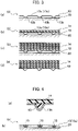
- Fig. 4(a) is a diagram illustrating a modification of the low-temperature tank according to the embodiment of the present disclosure
- Fig. 4(b) is a diagram illustrating a manufacturing process in the modification,.
- the low-temperature tank does further include a filler 15 filled between the bent portion 13b and the wall member 14.
- the matrix of a composite material constituting the wall member 14 has not been solidified. Therefore, there is a possibility that the matrix enters into the bent portion 13b of the metal liner 13.
- the matrix that has entered into the bent portion 13b adheres to the bent portion 13b and therefore, deformation of the bent portion 13b is hindered when the matrix is solidified.
- the filler 15 prevents the matrix from entering into the bent portion 13b. As illustrated in Fig. 4(b) , the filler 15 is filled in (applied on) the bent portion 13b after winding of the metal liner 13 around the mandrel 20 in Step S1 and before winding of the wall member 14 in Step S2 (Step S1').
- the filler 15 is formed of an elastic body that maintains its shape when being filled at the sintering temperature of the wall member 14. Further, the filler 15 has such a level of elasticity that the filler 15 does not interfere with deformation of the bent portion 13b.
- an elastic body is made of fluorocarbon polymers, for example.
- the filler 15 may be formed of a material that maintains its shape when being filled at a normal temperature and contracts at a sintering temperature of the wall member 14 or lower. That is, the filler 15 prevents entry of the matrix into the bent portion 13b by maintaining the shape illustrated in Fig. 4(a) when being filled in Step S2', and contracts during sintering in Step S3.
- a material is foamed polystyrene, for example.
- the filler 15 may remain after contraction. However, even in this case, the filler 15 does not affect the function of the metal liner 13 as a container and maintenance of the mechanical strength of the wall member 14.
- the sintered wall member 14 is not airtight.
- the sintered wall member 14 is gas-permeable (breathable). Therefore, even in a case of using a material that contracts at a sintering temperature or lower as the filler 15, an evaporation component and other expanding gas in the material are discharged through the wall member 14 to outside. Accordingly, contraction of the filler 15 does not affect maintenance of the shape of the solidified wall member 14.
- Fig. 5(a) is a diagram illustrating a first modification of the metal liner 13
- Fig. 5(b) is diagram illustrating a second modification of the metal liner 13.
- the metal liner 13 may have an uneven structure 13d in the adhering portion 13c.
- the uneven structure 13d is formed of fine grooves or undulation, as illustrated in Fig 5(a) , for example. Such structure is formed by surface roughening, such as scratching or blasting.
- the uneven structure 13d may be a projection that projects toward the wall member 14, as illustrated in Fig. 5(b) , for example. In either case, an area of contact of the adhering portion 13c with the wall member 14 (a composite material) is increased, so that the adhesion strength between the adhering portion 13c and the wall member 14 (a composite material) can be improved.
- the metal liner 13 ensures airtightness for storing a cryogenic liquid.
- the bent portion 13b of the metal liner 13 relaxes stress generated in a joining portion (a joining region) between the metal liner 13 and the wall member 14, which would cause peeling (detachment) due to thermal contraction or thermal expansion. Therefore, it is possible to prevent the metal liner 13 from peeling (detaching) from the wall member 14.
- the wall member 14 ensures the mechanical strength of the low-temperature tank. Because the wall member 14 is constituted by a composite material, the weight of the entire low-temperature tank is much lighter than a low-temperature tank that uses metal or concrete for a wall member.
- a low-temperature tank can be obtained which can withstand a harsh environment in which thermal contraction and thermal expansion are repeated, for example, in a rocket, and which is light and has sufficient strength.
- the metal liner 13 ensures airtightness, it is not necessary that the wall member 14 is airtight. Therefore, according to the manufacturing method of the present embodiment, strictness of handling of each constituent member and strictness of temperature control during sintering of the wall member 14 are relaxed as compared to those in a manufacturing method that requires airtightness for a composite material. That is, manufacturing processes are simplified, and the manufacturing cost can be also suppressed.
Landscapes
- Engineering & Computer Science (AREA)
- Mechanical Engineering (AREA)
- General Engineering & Computer Science (AREA)
- Physics & Mathematics (AREA)
- Thermal Sciences (AREA)
- Filling Or Discharging Of Gas Storage Vessels (AREA)
- Pressure Vessels And Lids Thereof (AREA)
- Moulding By Coating Moulds (AREA)
Description
- The present disclosure relates to a low-temperature tank for storing a cryogenic liquid and a method for manufacturing the same.
- Weight saving of constituent members is always demanded in a space vehicle such as a rocket. A tank for storing propellant is no exception, and weight saving by using a composite material using carbon fiber reinforced plastic (CFRP) has been proposed. In connection with this,
Patent Literature 1 discloses a tank for storing a cryogenic liquid. This tank includes a tank main body formed of a metal liner, and a composite material wound around the tank main body. - Patent Literature 2 discloses a high pressure vessel for containing or transporting pressurized gas or fuel, wherein a combination of a composite material wound around a metal liner is used in order to efficiently resist loads and stresses exposed to the vessel via the transported gas or fuel.
- Patent Literature 3 discloses a membrane with improved pressure withstanding properties for usage in a liquified natural gas container, by incorporating a reinforcing member for preventing corrugations of the membrane to collapse in result of heat and load.
-
- Patent Literature 1:
Japanese Patent No. 5948330 - Patent Literature 2: International Patent Application No.
WO 2013/083662 A2 - Patent Literature 3: US Patent Application No.
US 2015/114970 A1 - A linear expansion coefficient of a metal liner and a linear expansion coefficient of a composite material such as carbon fiber reinforced plastic are largely different from each other. Therefore, in a case of using these elements together as constituent members of a low-temperature tank for storing a cryogenic liquid, the metal liner may peel from the composite material because of thermal contraction or thermal expansion in association with filling and consumption of the liquid.
- The present disclosure has been made in view of the above circumstances, and it is an object to provide a low-temperature tank and a method for manufacturing the same that can prevent a metal liner, which is a constituent member of a container, from peeling from a composite material.
- A first aspect of the present disclosure is a low-temperature tank comprising a container main body that includes a metal liner forming a storage space of the low-temperature tank and a wall member formed of fiber reinforced plastic wound on an outer peripheral surface of the metal liner, wherein the metal liner includes a bent portion that extends in two directions intersecting each other on a surface thereof and that is bent to project toward the storage space, and the low-temperature tank further comprises a filler filled between the bent portion and the wall member, wherein the filler is formed of an elastic body that maintains a shape when being filled at a sintering temperature of the wall member.
- A second aspect of the present disclosure is a low-temperature tank comprising a container main body that includes a metal liner forming a storage space of the low-temperature tank and a wall member formed of fiber reinforced plastic wound on an outer peripheral surface of the metal liner, wherein the metal liner includes a bent portion that extends in two directions intersecting each other on a surface thereof and that is bent to project toward the storage space, and the low-temperature tank further comprises a filler filled between the bent portion and the wall member, wherein the filler is formed of a material that maintains a shape when being filled at a normal temperature and that contracts at a sintering temperature of the wall member or lower.
- A third aspect of the present disclosure is a method for manufacturing a low-temperature tank, the method comprising: winding a metal liner around a mandrel, the metal liner including a bent portion that extends in two directions intersecting each other on a surface thereof and is bent to project toward the mandrel; winding a wall member formed of fiber reinforced plastic on an outer peripheral surface of the metal liner wound around the mandrel; sintering the wall member; detaching the mandrel from the metal liner; and filling a filler into the bent portion.
- The metal liner may have an uneven structure in a portion adhering to the wall member.
- According to the present disclosure, it is possible to provide a low-temperature tank and a method for manufacturing the same that can prevent a metal liner, which is a constituent member of a container, from peeling from a wall member.
-
- [
Fig. 1] Fig. 1 is a cross-sectional diagram and a partially enlarged diagram of a low-temperature tank according to an embodiment of the present disclosure. - [
Fig. 2] Fig. 2(a) is a partially enlarged diagram of a metal liner according to the embodiment of the present disclosure, andFig. 2(b) is a cross-sectional diagram illustrating extension and contraction (shrinkage) of the metal liner and a wall member. - [
Fig. 3] Fig. 3 illustrates processes for manufacturing the low-temperature tank according to the embodiment of the present disclosure. - [
Fig. 4] Fig. 4(a) is a diagram illustrating a modification of the low-temperature tank according to the embodiment of the present disclosure, andFig. 4(b) is a diagram illustrating a manufacturing process in this modification. - [
Fig. 5] Fig. 5 illustrates modifications of the metal liner according to the embodiment of the present disclosure, whereFig. 5(a) is a diagram illustrating a first modification andFig. 5(b) is a diagram illustrating a second modification. - A low-temperature tank and a method for manufacturing the same according to an embodiment of the present disclosure will be described below with reference to the accompanying drawings. In the drawings, common parts are denoted by like reference signs and redundant explanations thereof will be omitted.
-
Fig. 1 is a cross-sectional diagram and a partially enlarged diagram of a low-temperature tank according to the present embodiment. The low-temperature tank according to the present embodiment is loaded on a space vehicle, such as a rocket. However, application of the low-temperature tank according to the present embodiment is not limited to a space vehicle, and can be applied to a vehicle, a vessel, storage facilities, and the like. Therefore, a cryogenic liquid stored (accommodated) in the low-temperature tank according to the present embodiment is not limited to propellant, such as liquid hydrogen, liquid oxygen, liquefied natural gas, and the like but may be liquid nitrogen or liquid helium that is general-purpose refrigerant. - As illustrated in
Fig. 1 , the low-temperature tank includes a hollow containermain body 10. The containermain body 10 hasports ports metal liner 13 described later by welding or the like. - The container
main body 10 includes themetal liner 13 that forms astorage space 12 for a liquid in the low-temperature tank, and awall member 14 wound on an outerperipheral surface 13a of themetal liner 13. Themetal liner 13 prevents leakage of the liquid from thestorage space 12. Thewall member 14 maintains the shape of themetal liner 13 and also ensures the mechanical strength of the entire low-temperature tank. - The
metal liner 13 is a thin metal plate. It is desirable that themetal liner 13 is light and has an appropriate level of malleability. Therefore, examples of the material of themetal liner 13 are aluminum, magnesium, and alloy containing at least one of these metals. The thickness of themetal liner 13 is set in accordance with the weight and workability that are required, and is set to about 0.5 mm, for example. - Meanwhile, the
wall member 14 is configured by a composite material that includes resin as a matrix and fiber impregnated with resin (that is, fiber reinforced plastic). Because the matrix before being sintered is adhesive, it adheres to the outerperipheral surface 13a of themetal liner 13. Thereafter, the composite material is sintered, so that the containermain body 10 has a double-wall structure of thewall member 14 and themetal liner 13. - It is desirable that the fiber of the composite material is light, has sufficient strength even at a cryogenic temperature, and is chemically stable. Fiber that satisfies this condition is carbon fiber, aramid fiber, and silicon carbide fiber, for example. It is desirable that the composite material is carbon fiber reinforced plastic (CFRP) that has highest strength. However, the composite material may be other fiber reinforced plastic (FRP), as long as the above condition is satisfied.
- As illustrated in
Figs. 1 and 2 , themetal liner 13 includes abent portion 13b and an adheringportion 13c. Thebent portion 13b extends in two directions that intersect each other on a surface of themetal liner 13 and is bent to project toward thestorage space 12. In other words, thebent portion 13b is bent to project toward inside of the containermain body 10. Thebent portion 13b is formed by press working of themetal liner 13, for example. Meanwhile, the adheringportion 13c is a portion (a surface) of themetal liner 13, other than thebent portion 13b, and is a flat surface or a curved surface that is smooth, for example. The adheringportion 13c couples thebent portions 13b that are adjacent to each other, and adheres to thewall member 14 by winding thewall member 14. - As described above, a linear expansion coefficient of metal and a linear expansion coefficient of a composite material are largely different from each other. Specifically, a linear expansion coefficient of metal is about an order of magnitude larger than a linear expansion coefficient of a composite material. Therefore, in a case where a low-temperature tank repeats thermal contraction (shrinkage) and thermal expansion in association with filling and consumption of a cryogenic liquid, this repetition of thermal contraction and thermal expansion may cause the
metal liner 13 to peel from thewall member 14. In the present embodiment, the adheringportion 13c may peel from thewall member 14. - On the other hand, the internal stress of the
metal liner 13, which prompts peeling of themetal liner 13, is relaxed by deformation of thebent portion 13b itself. As illustrated inFig. 1 , thebent portion 13b does not adhere to thewall member 14. Therefore, when the containermain body 10 thermally expands or contracts (shrinks), thebent portion 13b can be deformed (extend and contract, or be bent) without being affected by adhesion with thewall member 14. As a result, stress generated at a joining portion (a joining region) between themetal liner 13 and thewall member 14 is relaxed, so that it is possible to prevent themetal liner 13 from peeling from the wall member 14 (seeFig. 2(b) ). - The
bent portion 13b extends in two directions. The two extending directions are the 0 direction (the pole direction) and the φ direction (the azimuth direction) when the axis of rotational symmetry (the center axis) of the low-temperature tank is made coincident with a reference axis of a polar coordinate system (seeFig. 1 ). In this case, the two extending directions intersect each other at right angles. However, an angle formed by the intersecting two directions is not necessarily 90°, as long as appropriate extension or contraction of themetal liner 13, which enables the above peeling to be avoided, is obtained. - Next, a method for manufacturing a low-temperature tank according to the present embodiment is described.
Figs. 3(a) to 3(d) are diagrams illustrating manufacturing processes of the low-temperature tank according to the present embodiment. As illustrated in these drawings, the low-temperature tank according to the present embodiment is manufactured by using a mandrel (a cylindrical member) 20, for example. - First, the
metal liner 13 is wound around themandrel 20, as illustrated inFig. 3(a) (Step S1). Thebent portion 13b has to be bent to project toward thestorage space 12. Therefore, themetal liner 13 is wound on an outer peripheral surface of themandrel 20 in such a manner that thebent portion 13b projects toward themandrel 20. Edges of themetal liner 13 that are in contact with each other when themetal liner 13 is wound are joined to each other by welding or the like. - Next, as illustrated in
Fig. 3(b) , thewall member 14 is wound on the outerperipheral surface 13a of themetal liner 13 wound around the mandrel 20 (Step S2). At this time, thewall member 14 has not been heated yet, and the matrix of a composite material constituting thewall member 14 has not been solidified. Therefore, thewall member 14 has adhesiveness, and the composite material in a first layer adheres to the adheringportion 13c of themetal liner 13. The composite material of thewall member 14 is wound on the outerperipheral surface 13a of themetal liner 13 a plurality of times until a predetermined level of strength is obtained within an allowable weight range (seeFig. 3(c) ). A winding direction of the composite material may be changed every predetermined number of winding times (number of layers). By this winding, longitudinal (extending) directions of fiber as viewed in a thickness direction of thewall member 14 intersect each other, and therefore the strength of thewall member 14 is improved. - Next, the
wall member 14 wound around themetal liner 13 is sintered by a predetermined burner or in a heating furnace (Step S3). The temperature during this sintering is the temperature at which the matrix is solidified, and is 300°C, for example. By this sintering, the matrix of the composite material constituting thewall member 14 is solidified, so that the entire shape is maintained. - After being sintered, the
wall member 14 is cooled until it reaches a normal temperature, for example. In association with contraction during cooling, a number of minute gaps (i.e. cracks or voids) are formed in thewall member 14. These gaps provides gas-permeability (breathability) to thewall member 14. Thereafter, themandrel 20 is detached from themetal liner 13, as illustrated inFig. 3(d) (Step S4). Further, theport 11 and the like are joined, so as to form a low-temperature tank. Further joining may be performed for the metal liner and the wall member that have been subjected to the above processes, in accordance with the shape or the size of the low-temperature tank. -
Fig. 4(a) is a diagram illustrating a modification of the low-temperature tank according to the embodiment of the present disclosure, andFig. 4(b) is a diagram illustrating a manufacturing process in the modification,. As illustrated in these drawings, the low-temperature tank does further include afiller 15 filled between thebent portion 13b and thewall member 14. As described above, when thewall member 14 is wound on the outerperipheral surface 13a of themetal liner 13, the matrix of a composite material constituting thewall member 14 has not been solidified. Therefore, there is a possibility that the matrix enters into thebent portion 13b of themetal liner 13. The matrix that has entered into thebent portion 13b adheres to thebent portion 13b and therefore, deformation of thebent portion 13b is hindered when the matrix is solidified. - The
filler 15 prevents the matrix from entering into thebent portion 13b. As illustrated inFig. 4(b) , thefiller 15 is filled in (applied on) thebent portion 13b after winding of themetal liner 13 around themandrel 20 in Step S1 and before winding of thewall member 14 in Step S2 (Step S1'). - The
filler 15 is formed of an elastic body that maintains its shape when being filled at the sintering temperature of thewall member 14. Further, thefiller 15 has such a level of elasticity that thefiller 15 does not interfere with deformation of thebent portion 13b. Such an elastic body is made of fluorocarbon polymers, for example. - The
filler 15 may be formed of a material that maintains its shape when being filled at a normal temperature and contracts at a sintering temperature of thewall member 14 or lower. That is, thefiller 15 prevents entry of the matrix into thebent portion 13b by maintaining the shape illustrated inFig. 4(a) when being filled in Step S2', and contracts during sintering in Step S3. Such a material is foamed polystyrene, for example. Thefiller 15 may remain after contraction. However, even in this case, thefiller 15 does not affect the function of themetal liner 13 as a container and maintenance of the mechanical strength of thewall member 14. - The
sintered wall member 14 is not airtight. In other words, thesintered wall member 14 is gas-permeable (breathable). Therefore, even in a case of using a material that contracts at a sintering temperature or lower as thefiller 15, an evaporation component and other expanding gas in the material are discharged through thewall member 14 to outside. Accordingly, contraction of thefiller 15 does not affect maintenance of the shape of the solidifiedwall member 14. -
Fig. 5(a) is a diagram illustrating a first modification of themetal liner 13, andFig. 5(b) is diagram illustrating a second modification of themetal liner 13. As illustrated in these drawings, themetal liner 13 may have anuneven structure 13d in the adheringportion 13c. Theuneven structure 13d is formed of fine grooves or undulation, as illustrated inFig 5(a) , for example. Such structure is formed by surface roughening, such as scratching or blasting. Alternatively, theuneven structure 13d may be a projection that projects toward thewall member 14, as illustrated inFig. 5(b) , for example. In either case, an area of contact of the adheringportion 13c with the wall member 14 (a composite material) is increased, so that the adhesion strength between the adheringportion 13c and the wall member 14 (a composite material) can be improved. - According to the present embodiment, the
metal liner 13 ensures airtightness for storing a cryogenic liquid. When thermal contraction or thermal expansion of a low-temperature tank occurs, thebent portion 13b of themetal liner 13 relaxes stress generated in a joining portion (a joining region) between themetal liner 13 and thewall member 14, which would cause peeling (detachment) due to thermal contraction or thermal expansion. Therefore, it is possible to prevent themetal liner 13 from peeling (detaching) from thewall member 14. Meanwhile, thewall member 14 ensures the mechanical strength of the low-temperature tank. Because thewall member 14 is constituted by a composite material, the weight of the entire low-temperature tank is much lighter than a low-temperature tank that uses metal or concrete for a wall member. Therefore, a low-temperature tank can be obtained which can withstand a harsh environment in which thermal contraction and thermal expansion are repeated, for example, in a rocket, and which is light and has sufficient strength. Further, because themetal liner 13 ensures airtightness, it is not necessary that thewall member 14 is airtight. Therefore, according to the manufacturing method of the present embodiment, strictness of handling of each constituent member and strictness of temperature control during sintering of thewall member 14 are relaxed as compared to those in a manufacturing method that requires airtightness for a composite material. That is, manufacturing processes are simplified, and the manufacturing cost can be also suppressed.
Claims (6)
- A low-temperature tank comprisinga container main body (10) that includesa metal liner (13) forming a storage space of the low-temperature tank anda wall member (14) formed of fiber reinforced plastic wound on an outer peripheral surface (13a) of the metal liner (13), characterized in thatthe metal liner (13) includes a bent portion (13b) that extends in two directions intersecting each other on a surface thereof and that is bent to project toward the storage space; andthe low-temperature tank further comprises a filler (15) filled between the bent portion (13b) and the wall member (14), wherein the filler (15) is formed of an elastic body that maintains a shape when being filled at a sintering temperature of the wall member (14).
- A low-temperature tank comprisinga container main body (10) that includesa metal liner (13) forming a storage space of the low-temperature tank anda wall member (14) formed of fiber reinforced plastic wound on an outer peripheral surface (13a) of the metal liner (13), characterized in thatthe metal liner (13) includes a bent portion (13b) that extends in two directions intersecting each other on a surface thereof and that is bent to project toward the storage space; andthe low-temperature tank further comprises a filler (15) filled between the bent portion (13b) and the wall member (14), wherein the filler (15) is formed of a material that maintains a shape when being filled at a normal temperature and that contracts at a sintering temperature of the wall member (14) or lower.
- The low-temperature tank according to claim 1 or 2, wherein the metal liner (13) has an uneven structure in a portion (13c) adhering to the wall member (14).
- A method for manufacturing a low-temperature tank, the method comprising:winding a metal liner (13) around a mandrel (20);winding a wall member (14) formed of fiber reinforced plastic on an outer peripheral surface (13a) of the metal liner (13) wound around the mandrel (20);sintering the wall member (14);detaching the mandrel (20) from the metal liner (13);characterized in thatthe metal liner (13) wound around the mandrel (20) includes a bent portion (13b) that extends in two directions intersecting each other on a surface thereof and is bent to project toward the mandrel (20); andthe method further comprises filling a filler (15) into the bent (13b) portion.
- The method for manufacturing a low-temperature tank according to claim 4, wherein the filler (15) is formed of an elastic body that maintains a shape when being filled at a sintering temperature of the wall member (14).
- The method for manufacturing a low-temperature tank according to claim 4, wherein the filler (15) is formed of a material that maintains a shape when being filled at a normal temperature and that contracts at a sintering temperature of the wall member (14) or lower.
Applications Claiming Priority (2)
| Application Number | Priority Date | Filing Date | Title |
|---|---|---|---|
| JP2017055549 | 2017-03-22 | ||
| PCT/JP2017/038483 WO2018173348A1 (en) | 2017-03-22 | 2017-10-25 | Low-temperature tank and method for manufacturing same |
Publications (3)
| Publication Number | Publication Date |
|---|---|
| EP3556688A1 EP3556688A1 (en) | 2019-10-23 |
| EP3556688A4 EP3556688A4 (en) | 2020-07-29 |
| EP3556688B1 true EP3556688B1 (en) | 2023-03-01 |
Family
ID=63584304
Family Applications (1)
| Application Number | Title | Priority Date | Filing Date |
|---|---|---|---|
| EP17901669.6A Active EP3556688B1 (en) | 2017-03-22 | 2017-10-25 | Low-temperature tank and method for manufacturing same |
Country Status (5)
| Country | Link |
|---|---|
| US (1) | US11073243B2 (en) |
| EP (1) | EP3556688B1 (en) |
| JP (1) | JP6766948B2 (en) |
| RU (1) | RU2717931C1 (en) |
| WO (1) | WO2018173348A1 (en) |
Families Citing this family (4)
| Publication number | Priority date | Publication date | Assignee | Title |
|---|---|---|---|---|
| JP6601425B2 (en) * | 2017-01-18 | 2019-11-06 | トヨタ自動車株式会社 | Gas tank liners and gas tanks |
| CN111947022B (en) * | 2020-06-30 | 2022-10-25 | 同济大学 | Method for filling vehicle-mounted hydrogen storage bottle of fuel cell vehicle |
| CN113033509B (en) * | 2021-05-21 | 2021-08-24 | 中铁大桥科学研究院有限公司 | Method and equipment for monitoring and identifying temperature effect separation data of 5G-mode cable-stayed bridge |
| CN116428507A (en) * | 2023-06-12 | 2023-07-14 | 浙江大学 | Low-temperature heat-insulating container with interlayer gap compensation |
Family Cites Families (27)
| Publication number | Priority date | Publication date | Assignee | Title |
|---|---|---|---|---|
| BE619063A (en) * | 1961-06-20 | |||
| US3239092A (en) * | 1964-06-04 | 1966-03-08 | Whittaker Corp | Pressure vessel |
| FR1554714A (en) * | 1967-10-12 | 1969-01-24 | ||
| US3570701A (en) * | 1968-02-06 | 1971-03-16 | Bridgestone Liquefied Petroleu | Tank for use in storing low temperature liquefied gas |
| US3570700A (en) * | 1968-11-20 | 1971-03-16 | Bridgestone Liquefied Petroleu | Low temperature liquefied gas storage tank |
| JPS5162417A (en) * | 1974-11-27 | 1976-05-31 | Kawasaki Heavy Ind Ltd | TEIONEKI KAGASUTANKUNO GAIHYOMENBONETSUSOCHI |
| JPS5342889A (en) | 1976-09-30 | 1978-04-18 | Nippon Bunko Kogyo Kk | Measuring method of methabolism function of organ |
| JPS5948330B2 (en) | 1978-01-09 | 1984-11-26 | 日本電産コパル株式会社 | Zoom exposure meter |
| AU5948880A (en) * | 1979-11-01 | 1981-05-07 | Avon Industrial Polymers (Melksham) Ltd. | Inflatable partition |
| JPH0668359B2 (en) * | 1987-10-15 | 1994-08-31 | 帝人株式会社 | Composite material cylinder and method of manufacturing the same |
| US5150812A (en) * | 1990-07-05 | 1992-09-29 | Hoechst Celanese Corporation | Pressurized and/or cryogenic gas containers and conduits made with a gas impermeable polymer |
| JPH0988176A (en) * | 1995-09-22 | 1997-03-31 | Sekisui Chem Co Ltd | Septic tank |
| FR2739675B1 (en) * | 1995-10-05 | 1997-11-07 | Gaztransport Et Technigaz | LAND TANK FOR LOW TEMPERATURE LIQUID STORAGE |
| JPH11227881A (en) * | 1998-02-13 | 1999-08-24 | Ishikawajima Harima Heavy Ind Co Ltd | Liner for large-sized container |
| JP2002276894A (en) | 2001-03-21 | 2002-09-25 | Kajima Corp | Fitting method for cryogenic resistance obtundent of dike-integrated low temperature tank, dike-integrated low temperature tank, and insulating panel |
| FR2861060B1 (en) * | 2003-10-16 | 2006-01-06 | Gaz Transport & Technigaz | WATERPROOF STRUCTURE AND TANK PROVIDED WITH SUCH A STRUCTURE |
| JP2006017213A (en) * | 2004-07-01 | 2006-01-19 | Ishikawajima Harima Heavy Ind Co Ltd | Cold insulation sealing structure of low-temperature fluid storage tank |
| JP4940229B2 (en) * | 2006-03-28 | 2012-05-30 | 昭和電工株式会社 | Manufacturing method of liner component |
| US20110186580A1 (en) * | 2008-03-03 | 2011-08-04 | Samsung Heavy Ind. Co., Ltd. | Reinforcing member for corrugated membrane of lng cargo tank, membrane assembly having the reinforcing member and method for constructing the same |
| FR2936784B1 (en) * | 2008-10-08 | 2010-10-08 | Gaztransp Et Technigaz | REINFORCED CORRUGATED MEMBRANE TANK |
| FR2963659B1 (en) | 2010-08-03 | 2014-03-21 | Astrium Sas | CONNECTION BETWEEN METAL LINER AND COMPOSITE STRUCTURE IN THE EMBASE AREA OF A RESERVOIR |
| WO2013083652A2 (en) * | 2011-12-05 | 2013-06-13 | Blue Wave Co S.A. | Pressure vessel for fuel applications |
| WO2013109928A1 (en) * | 2012-01-20 | 2013-07-25 | Lightsail Energy Inc. | Compressed gas storage unit |
| FR3004141B1 (en) | 2013-04-03 | 2015-05-15 | Astrium Sas | CONNECTION BETWEEN A THIN METAL LINER AND A THERMOPLASTIC PARTICLE-LINKED COMPOSITE WALL |
| US20150192251A1 (en) * | 2014-01-07 | 2015-07-09 | Composite Technology Development, Inc. | High pressure carbon composite pressure vessel |
| RU2017122292A (en) | 2014-11-28 | 2018-12-28 | Мицубиси Гэс Кемикал Компани, Инк. | PRESSURE VESSEL, LINER AND METHOD FOR PRODUCING PRESSURE VESSEL |
| BR112018070505B1 (en) * | 2016-04-06 | 2022-11-29 | Hexagon Technology As | PRESSURE VESSEL, PRESSURE VESSEL BALL AND METHOD OF MANUFACTURING A PRESSURE VESSEL BALL |
-
2017
- 2017-10-25 RU RU2019132639A patent/RU2717931C1/en active
- 2017-10-25 JP JP2019506932A patent/JP6766948B2/en active Active
- 2017-10-25 EP EP17901669.6A patent/EP3556688B1/en active Active
- 2017-10-25 WO PCT/JP2017/038483 patent/WO2018173348A1/en unknown
-
2019
- 2019-06-25 US US16/451,220 patent/US11073243B2/en active Active
Also Published As
| Publication number | Publication date |
|---|---|
| RU2717931C1 (en) | 2020-03-26 |
| WO2018173348A1 (en) | 2018-09-27 |
| JPWO2018173348A1 (en) | 2019-11-07 |
| US11073243B2 (en) | 2021-07-27 |
| EP3556688A4 (en) | 2020-07-29 |
| EP3556688A1 (en) | 2019-10-23 |
| JP6766948B2 (en) | 2020-10-14 |
| US20190309905A1 (en) | 2019-10-10 |
Similar Documents
| Publication | Publication Date | Title |
|---|---|---|
| US11073243B2 (en) | Low-temperature tank and method for manufacturing same | |
| US20080256960A1 (en) | Vehicles incorporating tanks for carrying cryogenic fluids and methods for forming such tanks | |
| CA2366446C (en) | Improved systems and methods for producing and storing pressurized liquefied natural gas | |
| US11559964B2 (en) | Composite structures, composite storage tanks, vehicles including such composite storage tanks, and related systems and methods | |
| US5419139A (en) | Composite cryogenic tank apparatus | |
| US11845602B2 (en) | Tank and method | |
| US20100068561A1 (en) | Permeation protection for pressurized hydrogen storage tank | |
| US8763846B2 (en) | Bonding structure of metal member and composite-material member | |
| CA2706904C (en) | Liquefied natural gas pipeline with near zero coefficient of thermal expansion | |
| US20230332742A1 (en) | Method for coating a wall | |
| US20110168722A1 (en) | Full containment tank | |
| EP4105540B1 (en) | Storage tank for liquid hydrogen | |
| JP2010274565A (en) | Production process of high pressure tank for vehicle loading | |
| US20230313946A1 (en) | Tank feasible for cryogenic service | |
| KR100924099B1 (en) | Cargo containment system of lng ship and construction method thereof | |
| JP2005113971A (en) | Liner for pressure resistant container | |
| US20230035247A1 (en) | Hydrogen tank for aircraft | |
| Ladkany | Composite aluminum-fiberglass Epoxy pressure vessels for transportation of LNG at Intermediate Temperature | |
| JP2009257355A (en) | Pressure container and method for manufacturing the same | |
| Razin | The Problem of Optimum Design of Composite Housings of Solid Propellant Rocket Engines | |
| EP3984734B1 (en) | Storage tank for gaseous hydrogen | |
| KR20230153816A (en) | Method for Producing a Pressure Tank with Composite Materials | |
| JP2023103743A (en) | Cryogenic tank and manufacturing method of the same | |
| JP2023110517A (en) | Ultralow-temperature tank and manufacturing method of the same | |
| GB2626044A (en) | Cryogenic thermo-structural insulation system |
Legal Events
| Date | Code | Title | Description |
|---|---|---|---|
| STAA | Information on the status of an ep patent application or granted ep patent |
Free format text: STATUS: THE INTERNATIONAL PUBLICATION HAS BEEN MADE |
|
| PUAI | Public reference made under article 153(3) epc to a published international application that has entered the european phase |
Free format text: ORIGINAL CODE: 0009012 |
|
| STAA | Information on the status of an ep patent application or granted ep patent |
Free format text: STATUS: REQUEST FOR EXAMINATION WAS MADE |
|
| 17P | Request for examination filed |
Effective date: 20190718 |
|
| AK | Designated contracting states |
Kind code of ref document: A1 Designated state(s): AL AT BE BG CH CY CZ DE DK EE ES FI FR GB GR HR HU IE IS IT LI LT LU LV MC MK MT NL NO PL PT RO RS SE SI SK SM TR |
|
| AX | Request for extension of the european patent |
Extension state: BA ME |
|
| DAV | Request for validation of the european patent (deleted) | ||
| DAX | Request for extension of the european patent (deleted) | ||
| A4 | Supplementary search report drawn up and despatched |
Effective date: 20200629 |
|
| RIC1 | Information provided on ipc code assigned before grant |
Ipc: B64G 1/40 20060101ALI20200624BHEP Ipc: B65D 90/04 20060101AFI20200624BHEP Ipc: F17C 1/00 20060101ALI20200624BHEP |
|
| GRAP | Despatch of communication of intention to grant a patent |
Free format text: ORIGINAL CODE: EPIDOSNIGR1 |
|
| STAA | Information on the status of an ep patent application or granted ep patent |
Free format text: STATUS: GRANT OF PATENT IS INTENDED |
|
| RIC1 | Information provided on ipc code assigned before grant |
Ipc: F17C 1/00 20060101ALI20220901BHEP Ipc: B64G 1/40 20060101ALI20220901BHEP Ipc: B65D 90/04 20060101AFI20220901BHEP |
|
| INTG | Intention to grant announced |
Effective date: 20220929 |
|
| GRAS | Grant fee paid |
Free format text: ORIGINAL CODE: EPIDOSNIGR3 |
|
| GRAA | (expected) grant |
Free format text: ORIGINAL CODE: 0009210 |
|
| STAA | Information on the status of an ep patent application or granted ep patent |
Free format text: STATUS: THE PATENT HAS BEEN GRANTED |
|
| AK | Designated contracting states |
Kind code of ref document: B1 Designated state(s): AL AT BE BG CH CY CZ DE DK EE ES FI FR GB GR HR HU IE IS IT LI LT LU LV MC MK MT NL NO PL PT RO RS SE SI SK SM TR |
|
| REG | Reference to a national code |
Ref country code: GB Ref legal event code: FG4D |
|
| REG | Reference to a national code |
Ref country code: CH Ref legal event code: EP Ref country code: AT Ref legal event code: REF Ref document number: 1550828 Country of ref document: AT Kind code of ref document: T Effective date: 20230315 |
|
| REG | Reference to a national code |
Ref country code: DE Ref legal event code: R096 Ref document number: 602017066518 Country of ref document: DE |
|
| REG | Reference to a national code |
Ref country code: IE Ref legal event code: FG4D |
|
| REG | Reference to a national code |
Ref country code: LT Ref legal event code: MG9D |
|
| REG | Reference to a national code |
Ref country code: NL Ref legal event code: MP Effective date: 20230301 |
|
| PG25 | Lapsed in a contracting state [announced via postgrant information from national office to epo] |
Ref country code: RS Free format text: LAPSE BECAUSE OF FAILURE TO SUBMIT A TRANSLATION OF THE DESCRIPTION OR TO PAY THE FEE WITHIN THE PRESCRIBED TIME-LIMIT Effective date: 20230301 Ref country code: NO Free format text: LAPSE BECAUSE OF FAILURE TO SUBMIT A TRANSLATION OF THE DESCRIPTION OR TO PAY THE FEE WITHIN THE PRESCRIBED TIME-LIMIT Effective date: 20230601 Ref country code: LV Free format text: LAPSE BECAUSE OF FAILURE TO SUBMIT A TRANSLATION OF THE DESCRIPTION OR TO PAY THE FEE WITHIN THE PRESCRIBED TIME-LIMIT Effective date: 20230301 Ref country code: LT Free format text: LAPSE BECAUSE OF FAILURE TO SUBMIT A TRANSLATION OF THE DESCRIPTION OR TO PAY THE FEE WITHIN THE PRESCRIBED TIME-LIMIT Effective date: 20230301 Ref country code: HR Free format text: LAPSE BECAUSE OF FAILURE TO SUBMIT A TRANSLATION OF THE DESCRIPTION OR TO PAY THE FEE WITHIN THE PRESCRIBED TIME-LIMIT Effective date: 20230301 Ref country code: ES Free format text: LAPSE BECAUSE OF FAILURE TO SUBMIT A TRANSLATION OF THE DESCRIPTION OR TO PAY THE FEE WITHIN THE PRESCRIBED TIME-LIMIT Effective date: 20230301 |
|
| REG | Reference to a national code |
Ref country code: AT Ref legal event code: MK05 Ref document number: 1550828 Country of ref document: AT Kind code of ref document: T Effective date: 20230301 |
|
| PG25 | Lapsed in a contracting state [announced via postgrant information from national office to epo] |
Ref country code: SE Free format text: LAPSE BECAUSE OF FAILURE TO SUBMIT A TRANSLATION OF THE DESCRIPTION OR TO PAY THE FEE WITHIN THE PRESCRIBED TIME-LIMIT Effective date: 20230301 Ref country code: PL Free format text: LAPSE BECAUSE OF FAILURE TO SUBMIT A TRANSLATION OF THE DESCRIPTION OR TO PAY THE FEE WITHIN THE PRESCRIBED TIME-LIMIT Effective date: 20230301 Ref country code: NL Free format text: LAPSE BECAUSE OF FAILURE TO SUBMIT A TRANSLATION OF THE DESCRIPTION OR TO PAY THE FEE WITHIN THE PRESCRIBED TIME-LIMIT Effective date: 20230301 Ref country code: GR Free format text: LAPSE BECAUSE OF FAILURE TO SUBMIT A TRANSLATION OF THE DESCRIPTION OR TO PAY THE FEE WITHIN THE PRESCRIBED TIME-LIMIT Effective date: 20230602 Ref country code: FI Free format text: LAPSE BECAUSE OF FAILURE TO SUBMIT A TRANSLATION OF THE DESCRIPTION OR TO PAY THE FEE WITHIN THE PRESCRIBED TIME-LIMIT Effective date: 20230301 |
|
| PG25 | Lapsed in a contracting state [announced via postgrant information from national office to epo] |
Ref country code: SM Free format text: LAPSE BECAUSE OF FAILURE TO SUBMIT A TRANSLATION OF THE DESCRIPTION OR TO PAY THE FEE WITHIN THE PRESCRIBED TIME-LIMIT Effective date: 20230301 Ref country code: RO Free format text: LAPSE BECAUSE OF FAILURE TO SUBMIT A TRANSLATION OF THE DESCRIPTION OR TO PAY THE FEE WITHIN THE PRESCRIBED TIME-LIMIT Effective date: 20230301 Ref country code: PT Free format text: LAPSE BECAUSE OF FAILURE TO SUBMIT A TRANSLATION OF THE DESCRIPTION OR TO PAY THE FEE WITHIN THE PRESCRIBED TIME-LIMIT Effective date: 20230703 Ref country code: EE Free format text: LAPSE BECAUSE OF FAILURE TO SUBMIT A TRANSLATION OF THE DESCRIPTION OR TO PAY THE FEE WITHIN THE PRESCRIBED TIME-LIMIT Effective date: 20230301 Ref country code: CZ Free format text: LAPSE BECAUSE OF FAILURE TO SUBMIT A TRANSLATION OF THE DESCRIPTION OR TO PAY THE FEE WITHIN THE PRESCRIBED TIME-LIMIT Effective date: 20230301 Ref country code: AT Free format text: LAPSE BECAUSE OF FAILURE TO SUBMIT A TRANSLATION OF THE DESCRIPTION OR TO PAY THE FEE WITHIN THE PRESCRIBED TIME-LIMIT Effective date: 20230301 |
|
| PG25 | Lapsed in a contracting state [announced via postgrant information from national office to epo] |
Ref country code: SK Free format text: LAPSE BECAUSE OF FAILURE TO SUBMIT A TRANSLATION OF THE DESCRIPTION OR TO PAY THE FEE WITHIN THE PRESCRIBED TIME-LIMIT Effective date: 20230301 Ref country code: IS Free format text: LAPSE BECAUSE OF FAILURE TO SUBMIT A TRANSLATION OF THE DESCRIPTION OR TO PAY THE FEE WITHIN THE PRESCRIBED TIME-LIMIT Effective date: 20230701 |
|
| REG | Reference to a national code |
Ref country code: DE Ref legal event code: R097 Ref document number: 602017066518 Country of ref document: DE |
|
| PLBE | No opposition filed within time limit |
Free format text: ORIGINAL CODE: 0009261 |
|
| STAA | Information on the status of an ep patent application or granted ep patent |
Free format text: STATUS: NO OPPOSITION FILED WITHIN TIME LIMIT |
|
| PG25 | Lapsed in a contracting state [announced via postgrant information from national office to epo] |
Ref country code: SI Free format text: LAPSE BECAUSE OF FAILURE TO SUBMIT A TRANSLATION OF THE DESCRIPTION OR TO PAY THE FEE WITHIN THE PRESCRIBED TIME-LIMIT Effective date: 20230301 Ref country code: DK Free format text: LAPSE BECAUSE OF FAILURE TO SUBMIT A TRANSLATION OF THE DESCRIPTION OR TO PAY THE FEE WITHIN THE PRESCRIBED TIME-LIMIT Effective date: 20230301 |
|
| PGFP | Annual fee paid to national office [announced via postgrant information from national office to epo] |
Ref country code: DE Payment date: 20231031 Year of fee payment: 7 |
|
| 26N | No opposition filed |
Effective date: 20231204 |
|
| PG25 | Lapsed in a contracting state [announced via postgrant information from national office to epo] |
Ref country code: IT Free format text: LAPSE BECAUSE OF FAILURE TO SUBMIT A TRANSLATION OF THE DESCRIPTION OR TO PAY THE FEE WITHIN THE PRESCRIBED TIME-LIMIT Effective date: 20230301 Ref country code: MC Free format text: LAPSE BECAUSE OF FAILURE TO SUBMIT A TRANSLATION OF THE DESCRIPTION OR TO PAY THE FEE WITHIN THE PRESCRIBED TIME-LIMIT Effective date: 20230301 |
|
| REG | Reference to a national code |
Ref country code: CH Ref legal event code: PL |
|
| REG | Reference to a national code |
Ref country code: BE Ref legal event code: MM Effective date: 20231031 |
|
| PG25 | Lapsed in a contracting state [announced via postgrant information from national office to epo] |
Ref country code: LU Free format text: LAPSE BECAUSE OF NON-PAYMENT OF DUE FEES Effective date: 20231025 |
|
| GBPC | Gb: european patent ceased through non-payment of renewal fee |
Effective date: 20231025 |
|
| PG25 | Lapsed in a contracting state [announced via postgrant information from national office to epo] |
Ref country code: LU Free format text: LAPSE BECAUSE OF NON-PAYMENT OF DUE FEES Effective date: 20231025 |
|
| PG25 | Lapsed in a contracting state [announced via postgrant information from national office to epo] |
Ref country code: GB Free format text: LAPSE BECAUSE OF NON-PAYMENT OF DUE FEES Effective date: 20231025 |
|
| PG25 | Lapsed in a contracting state [announced via postgrant information from national office to epo] |
Ref country code: CH Free format text: LAPSE BECAUSE OF NON-PAYMENT OF DUE FEES Effective date: 20231031 |
|
| PG25 | Lapsed in a contracting state [announced via postgrant information from national office to epo] |
Ref country code: GB Free format text: LAPSE BECAUSE OF NON-PAYMENT OF DUE FEES Effective date: 20231025 Ref country code: FR Free format text: LAPSE BECAUSE OF NON-PAYMENT OF DUE FEES Effective date: 20231031 Ref country code: CH Free format text: LAPSE BECAUSE OF NON-PAYMENT OF DUE FEES Effective date: 20231031 |
|
| PG25 | Lapsed in a contracting state [announced via postgrant information from national office to epo] |
Ref country code: BE Free format text: LAPSE BECAUSE OF NON-PAYMENT OF DUE FEES Effective date: 20231031 |