EP2599512B1 - Inhalateur d'extraction à air chaud doté d'un chauffage combinant air et rayonnement - Google Patents
Inhalateur d'extraction à air chaud doté d'un chauffage combinant air et rayonnement Download PDFInfo
- Publication number
- EP2599512B1 EP2599512B1 EP11401648.8A EP11401648A EP2599512B1 EP 2599512 B1 EP2599512 B1 EP 2599512B1 EP 11401648 A EP11401648 A EP 11401648A EP 2599512 B1 EP2599512 B1 EP 2599512B1
- Authority
- EP
- European Patent Office
- Prior art keywords
- inhaler
- hot air
- housing
- heat exchanger
- filling chamber
- Prior art date
- Legal status (The legal status is an assumption and is not a legal conclusion. Google has not performed a legal analysis and makes no representation as to the accuracy of the status listed.)
- Active
Links
- 238000000605 extraction Methods 0.000 title claims description 31
- 238000010438 heat treatment Methods 0.000 title description 14
- 239000000126 substance Substances 0.000 claims description 34
- 239000000443 aerosol Substances 0.000 claims description 12
- 239000004020 conductor Substances 0.000 claims description 2
- 239000000203 mixture Substances 0.000 claims description 2
- 238000010276 construction Methods 0.000 claims 1
- 239000003570 air Substances 0.000 description 74
- 238000001704 evaporation Methods 0.000 description 11
- 230000008020 evaporation Effects 0.000 description 11
- 239000004480 active ingredient Substances 0.000 description 5
- 239000000463 material Substances 0.000 description 5
- 230000005855 radiation Effects 0.000 description 4
- 239000000796 flavoring agent Substances 0.000 description 3
- 235000019634 flavors Nutrition 0.000 description 3
- 235000008216 herbs Nutrition 0.000 description 3
- 210000004072 lung Anatomy 0.000 description 3
- 238000000034 method Methods 0.000 description 3
- 239000013543 active substance Substances 0.000 description 2
- 238000009835 boiling Methods 0.000 description 2
- 238000005485 electric heating Methods 0.000 description 2
- 230000013011 mating Effects 0.000 description 2
- 239000002184 metal Substances 0.000 description 2
- 230000002093 peripheral effect Effects 0.000 description 2
- 230000001225 therapeutic effect Effects 0.000 description 2
- XLYOFNOQVPJJNP-UHFFFAOYSA-N water Substances O XLYOFNOQVPJJNP-UHFFFAOYSA-N 0.000 description 2
- 239000012080 ambient air Substances 0.000 description 1
- 230000015572 biosynthetic process Effects 0.000 description 1
- 238000007664 blowing Methods 0.000 description 1
- 238000004140 cleaning Methods 0.000 description 1
- 230000000295 complement effect Effects 0.000 description 1
- 230000001419 dependent effect Effects 0.000 description 1
- 239000003814 drug Substances 0.000 description 1
- 229940079593 drug Drugs 0.000 description 1
- 238000001035 drying Methods 0.000 description 1
- 238000009413 insulation Methods 0.000 description 1
- 239000007788 liquid Substances 0.000 description 1
- 238000004519 manufacturing process Methods 0.000 description 1
- 230000001681 protective effect Effects 0.000 description 1
- 239000007787 solid Substances 0.000 description 1
- 239000000758 substrate Substances 0.000 description 1
- 238000002207 thermal evaporation Methods 0.000 description 1
- 238000009834 vaporization Methods 0.000 description 1
- 230000008016 vaporization Effects 0.000 description 1
- 238000009423 ventilation Methods 0.000 description 1
Images
Classifications
-
- A—HUMAN NECESSITIES
- A61—MEDICAL OR VETERINARY SCIENCE; HYGIENE
- A61M—DEVICES FOR INTRODUCING MEDIA INTO, OR ONTO, THE BODY; DEVICES FOR TRANSDUCING BODY MEDIA OR FOR TAKING MEDIA FROM THE BODY; DEVICES FOR PRODUCING OR ENDING SLEEP OR STUPOR
- A61M15/00—Inhalators
- A61M15/009—Inhalators using medicine packages with incorporated spraying means, e.g. aerosol cans
-
- A—HUMAN NECESSITIES
- A61—MEDICAL OR VETERINARY SCIENCE; HYGIENE
- A61M—DEVICES FOR INTRODUCING MEDIA INTO, OR ONTO, THE BODY; DEVICES FOR TRANSDUCING BODY MEDIA OR FOR TAKING MEDIA FROM THE BODY; DEVICES FOR PRODUCING OR ENDING SLEEP OR STUPOR
- A61M11/00—Sprayers or atomisers specially adapted for therapeutic purposes
- A61M11/04—Sprayers or atomisers specially adapted for therapeutic purposes operated by the vapour pressure of the liquid to be sprayed or atomised
- A61M11/041—Sprayers or atomisers specially adapted for therapeutic purposes operated by the vapour pressure of the liquid to be sprayed or atomised using heaters
- A61M11/042—Sprayers or atomisers specially adapted for therapeutic purposes operated by the vapour pressure of the liquid to be sprayed or atomised using heaters electrical
-
- A—HUMAN NECESSITIES
- A61—MEDICAL OR VETERINARY SCIENCE; HYGIENE
- A61M—DEVICES FOR INTRODUCING MEDIA INTO, OR ONTO, THE BODY; DEVICES FOR TRANSDUCING BODY MEDIA OR FOR TAKING MEDIA FROM THE BODY; DEVICES FOR PRODUCING OR ENDING SLEEP OR STUPOR
- A61M15/00—Inhalators
-
- A—HUMAN NECESSITIES
- A61—MEDICAL OR VETERINARY SCIENCE; HYGIENE
- A61M—DEVICES FOR INTRODUCING MEDIA INTO, OR ONTO, THE BODY; DEVICES FOR TRANSDUCING BODY MEDIA OR FOR TAKING MEDIA FROM THE BODY; DEVICES FOR PRODUCING OR ENDING SLEEP OR STUPOR
- A61M2205/00—General characteristics of the apparatus
- A61M2205/33—Controlling, regulating or measuring
- A61M2205/3368—Temperature
-
- A—HUMAN NECESSITIES
- A61—MEDICAL OR VETERINARY SCIENCE; HYGIENE
- A61M—DEVICES FOR INTRODUCING MEDIA INTO, OR ONTO, THE BODY; DEVICES FOR TRANSDUCING BODY MEDIA OR FOR TAKING MEDIA FROM THE BODY; DEVICES FOR PRODUCING OR ENDING SLEEP OR STUPOR
- A61M2205/00—General characteristics of the apparatus
- A61M2205/36—General characteristics of the apparatus related to heating or cooling
- A61M2205/3653—General characteristics of the apparatus related to heating or cooling by Joule effect, i.e. electric resistance
Definitions
- the invention relates to a H strictly poverty extractsinhalator, with a heater for heating under heat aerosol forming substances passing through the air pass into the air and inhaled either via a buffer or directly from the inhaler via an inhalation line with mouthpiece out.
- Such therapeutic vaporization devices for the production of aroma and / or active substance vapors for inhalation are known from the prior art in various embodiments. Exemplary is the patents DE 100 42 396 B4 and DE 198 03 376 C1 directed. The inhalers described there are used for thermal evaporation and subsequent inhalation of vaporizable, ie under heat aerosol forming substances.
- Simple H exertizi Kunststoffextraktionsinhalatoren have only a heated filling chamber for heating the substances to be evaporated by means of thermal radiation.
- This design is inexpensive, but allows only insufficient evaporation, since during inhalation, the inflowing unheated air cools the filling chamber and the substances contained therein again, thereby interrupting the evaporation process. It must then be maintained until the radiant heat of the filling chamber contained Substances has heated sufficiently for evaporation again.
- Hot air extraction inhalers which only work with thermal radiation, are suitable at most for the evaporation of pure substances, for the evaporation of flavors and active ingredients from medicinal herbs, they are only limited use.
- Much more productive is the method in which the substances are exposed to a hot air flow, which is heated when passing through a heat generator.
- the hot air flows through the filling chamber with the substances, wherein the substances evaporate or expel their active ingredients such as herbs from a substrate out (extract), which then pass into the hot air.
- This for example, flavored and / or actives laden hot air is inhaled as inhaled air, after it has been cooled down to a comfortable temperature for inhalation, the active ingredients after inhalation through the lungs enter the bloodstream.
- medicinal herbs or other suitable herbal substances which are suitably comminuted according to the purpose of use or else synthetic substances with therapeutic active substances present in pulverized form are frequently used. It can also be vaporized liquid substances.
- the European patent application EP 0 858 744 A1 discloses a hot air extraction inhaler with a tube pluggable through a gas-heated heating channel.
- the tube In the area located in the heating channel, the tube includes a cylindrical body interspersed with through-holes and containing substances to be vaporized. Air drawn through the tube heats up in the through holes and vaporizes the contained substances.
- a big disadvantage of the known evaporator is that the air is cold in the through holes of the vaporizable substances containing cylinder flows. An evaporation takes place only when the air has been sufficiently heated, that is only in a rear direction in the flow direction of the cylindrical, the vaporizable substances contained cylinder. In a front area in the flow direction is not evaporated, because the air flows cold.
- a heat generator which has at least one air channel for the air flow to be heated.
- the air duct can pass through the heat generator inside or outside.
- electric heating wires are mounted open in the air duct.
- the air flow can be generated by suction of air at an outlet opening or the other by blowing air into an inlet opening of the air duct, wherein the required positive or negative pressure by means of lung power or using a blower or a pump, for example a Diaphragm pump, can be built.
- the ambient air flowing into the air duct at an inhaler inlet is heated from room temperature to, for example, 200 ° C. in dependence on the temperature emanating from the heat generator and the volume flow through the air duct.
- the temperature is adjusted to the boiling or extraction point of the aerosol-forming substances used for the inhalation, so that their active ingredients and / or flavors evaporate as the hot air flow passes through the filling chamber and the aerosols are taken up by the air flow.
- the aerosol-laden air stream is available as inhaled air for inhalation.
- the hot air stream must heat both the cold substances and the cold surrounding filling chamber, so that evaporation of these substances can take place at all.
- the present invention seeks to propose a way in which the user of Hippobuchextraktionsinhalatoren where inhaled directly from the inhaler out, as soon as possible with the first inhalation and then constantly flavor and drug-rich vapors.
- the core idea of the invention is to improve the heating of hot air extraction inhalers so that both an immediate, as well as during the inhalation train continuous evaporation can take place.
- the H. povertyexktrationsinhalator invention has a heater that heats both a filling chamber with content, as well as is able to generate a hot air flow, which is passed through the filling chamber with content.
- the heater which may be designed as a solid heat exchanger with one or more performed air ducts, preferably in one embodiment a filling chamber integrated in the heat exchanger and in another preferred embodiment a removable, but in an attached state via a contact surface thermally connected to the heat exchanger filling chamber on.
- the inner wall of the filling chamber is formed in both cases so that the Racinhalt is heated by radiant heat.
- the heated inner wall of the filling chamber heats its contents by radiant heat and at the edge by thermal contact of the contents with the inner wall of the filling chamber, regardless of whether hot air flows through the filling chamber or not.
- the heating of the filling chamber is sufficient to heat substances contained in it to a temperature which is formed at the aerosol and to keep it at this temperature, when the filling chamber is not traversed by air. If the filling chamber is traversed by air, this has been previously heated, so that they are the contents of Filling chamber does not cool, but keeps on the aerosol-forming temperature or heated together with the filling chamber to this temperature.
- the invention is directed to hot air extraction inhalers for direct inhalation of a user, it is not limited to such hot air inhalation inhalers but is generally directed to generic hot air extraction inhalers.
- the invention is also advantageous, for example, for hot air extraction inhalers, which have a buffer in which the aerosol / air mixture is first pumped and then inhaled later out of it.
- the filling chamber consists of an inner, good heat conducting part of e.g. Metal, which in particular forms the inner wall of the filling chamber or an inner chamber housing, and an outer, good heat-insulating circumferential part made of e.g. Plastic.
- the inner chamber housing is part of the heat exchanger.
- the heat-conducting inner chamber housing for example, frontally applied to the heat exchanger. This allows during the heating or even in already heated heat exchanger rapid heat transfer from the heat exchanger to the inner chamber housing by means of direct heat conduction.
- the inner chamber housing which surrounds the filling chamber for the substances to be evaporated and limited, from a good heat conducting material such. Metal.
- the inner chamber housing is cylindrical and guided axially movable in the inhaler housing. This is particularly advantageous if the heat exchanger also has a substantially cylindrical contour.
- the inner chamber housing can be arranged with the filling chamber in a simple manner end face and coaxial with the air duct on the heat exchanger such that the exiting the heat exchanger air flow passed through air passage openings in a bottom and a lid of the filling chamber through the therein provided for hot air extraction substances can be.
- the bottom and / or the lid of the filling chamber can also be formed in the usual way by a metallic wire mesh.
- the removable filling chamber has a thread on the circumference which interacts with a mating thread of the inhaler housing.
- the thread may be formed on an inner circumference or on an outer circumference of the filling chamber, wherein the mating thread of the inhaler housing is in each case formed complementary thereto and arranged corresponding thereto.
- the outer chamber housing has a thermally insulating actuating lever for rotating the chamber housing or the filling chamber relative to the inhaler housing. This burns when removing or placing the filling chamber are reliably avoided to the heated heat exchanger.
- the inhaler housing is designed in the manner of a hand-held device with a handle.
- an inhaler housing area enclosing the heat exchanger can be designed as a handle or the inhaler housing has a laterally arranged handle.
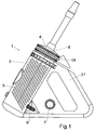
- FIG. 1 1 shows an exemplary embodiment of a hot air extraction inhaler 1 according to the invention with an inhaler housing 2, in which a heat exchanger 3 which is thermally insulated towards the inhaler housing 2 is shown.
- FIG. 2 to the Heating an air flow is arranged.
- an inhaler outlet 4 of the hot air extraction inhaler 1 is subjected to negative pressure, that is to say, for example, when air is inhaled from the hot air extraction inhaler 1 through the inhaler outlet 4
- the heat exchanger 3 is electrically heated, wherein the temperature with a temperature selector 6 selectable and the supply voltage via a mains voltage switch 7 is switchable.
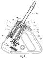
- FIG. 2 shows the interior of the inhaler housing 2 in an axial sectional view.
- the inhaler housing 2 As essential parts, the inhaler housing 2, the heat exchanger 3 and a filling chamber 8 for aerosol-forming substances under heat, which is arranged in the flow direction in extension of the heat exchanger 3 between the Inhalatorauslass 4 and the heat exchanger 3.
- the heat exchanger 3 has a central electric heating cartridge 9 and two coiled air ducts 10 which are peripherally closed on the outside of an outer tube 11.
- the outer tube 11 is surrounded by an insulating jacket 12 for thermal insulation of the heat exchanger 3 relative to the inhaler housing 2.
- the heating cartridge 9 and the heat exchanger 3, together with the outer tube 11, form a heater of the hot air extraction inhaler 1.
- the filling chamber 8 has an inner chamber housing 13 with a chamber bottom 14 and the inhaler outlet 4 with a chamber lid 15, wherein the inhaler outlet 4 for filling and emptying the filling chamber 8 of the outer chamber housing 18 is releasable.
- the filling chamber 8 is arranged coaxially with the heat exchanger 3 and guided in the axial direction in the inhaler housing 2 axially movable.
- the filling chamber 8 is removable by means of a thermally insulating actuating lever 16.
- the inhaler outlet 4 is bell-shaped and has a heat-insulating design.
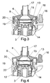
- FIG. 3 shows an enlarged detail of the inhaler outlet 4 facing the end of the heat exchanger 3 and the flow direction then arranged in the filling chamber 8 with the following inhaler 4. clearer than in the FIG. 2 the filling chamber 8 with the inner chamber housing 13, the outer chamber housing 18, the chamber bottom 14 and the chamber lid 15 can be seen.
- the filling chamber 8 can be opened by removing the inhaler outlet 4 together with the suction tube 17 and the chamber lid 15 from the inner and outer chamber housings 13 and 18.
- the FIG. 3 shows the inner chamber housing 13 end face in contact with the heat exchanger 3, wherein a direct thermal contact between the heated heat exchanger 3 and the inner chamber housing 13 is made, so that the inner chamber housing 13 heated by heat conduction and located in the filling chamber 8, in the drawing not shown aerosol forming substance by means of thermal radiation, starting from the inner chamber housing 13 is heated.
- the filling chamber 8 can be removed in this preferred embodiment for convenient emptying, cleaning and filling in the axial direction of the heat exchanger 3.
- the chamber housing 13 is rotated by means of the radially projecting actuating lever 16, which engages the outer chamber housing 18, relative to the heat exchanger 3 and the inhaler housing 2 in the circumferential direction of the filling chamber 8.
- the inner chamber housing 13 has a positive and / or non-positively connected outer chamber housing 18, on which the actuating lever 16 is formed and thus rotatably connected.
- the outer chamber housing 18, which surrounds the inner chamber housing 13, has a thread 19 on the outer peripheral side facing the inhaler housing 2, which thread is formed in the illustrated embodiment by helical vanes.
- the helical wings act with an associated Internal thread 20 in the inhaler housing 2 together.
- the filling chamber 8 moves toward or away from the heat exchanger 3.
- FIG. 4 also shows a section of the inhaler outlet 4 facing the end of the heat exchanger 3 and arranged in the flow direction then filling chamber 8 with the following inhaler 4.
- FIG. 4 shows the FIG. 4 an integrated in the heat exchanger 3 inner chamber housing 13 of the filling chamber 8.
- the heat exchanger 3 and the inner chamber housing 13 here form a common, integrally executed part.
- the outer chamber housing 18 is omitted FIG. 4 and is replaced by a protective cylinder 22 which is made together with the insulating jacket 12 together in one piece.
- the actuating lever 16 is embodied here in one piece with the inhaler outlet 4.
- the filling chamber 8 can be opened by removing the inhaler outlet 4 together with the suction hose 17 and the chamber lid 15 from the inner chamber housing 13.
- the FIG. 4 shows the inner chamber housing 13 together as one piece with the heat exchanger 3, wherein a direct thermal connection between the heated heat exchanger 3 and the inner chamber housing 13, so that the inner chamber housing 13 is heated by heat conduction and located in the filling chamber 8, in the drawing, not shown aerosol forming substance by means of thermal radiation, starting from the inner chamber housing 13 and partly heated by the heat exchanger 3.
- the inhaler outlet 4 can be removed in this embodiment in the axial direction of the filling chamber 8.
- the inhaler outlet 4 is rotated relative to the heat exchanger 3 and the inhaler housing 2 in the circumferential direction of the filling chamber 8 by means of the radially projecting actuating lever 16, which acts on the inhaler outlet 4.
- the inhaler outlet 4 is connected to the Actuator 16 rotatably connected.
- the inhaler outlet 4 has, on the outer peripheral side directed toward the inhaler housing 2, a thread 19, which in the illustrated embodiment is formed by helical blades.
- the spiral vanes 19 cooperate with an associated internal thread 20 in the inhaler housing 2.
- the filling chamber 8 moves toward or away from the heat exchanger 3.
- the in the FIGS. 1 to 4 illustrated hot air extraction inhaler 1 according to the invention is preferably used as a stand-alone and as a hand-held device.
- the inhaler housing 2 is designed in the manner of a hand-held device with a handle 21 on one side of the inhaler housing 2.
Claims (9)
- Inhalateur à extraction par air chaud (1), comprenant un échangeur de chaleur (3) qui est en mesure de produire un courant d'air chaud, une chambre de remplissage (8) prévue pour être remplie de substances formant un aérosol sous l'effet de la chaleur, à travers laquelle le courant d'air chaud de l'échangeur de chaleur est conduit, et d'une sortie d'inhalateur (4) pour inhaler le mélange aérosol/air, caractérisé en ce que la chambre de remplissage (8) présente un boîtier de chambre intérieur (13) dans un matériau bon conducteur de la chaleur et qu'on utilise un échangeur de chaleur (3) qui à la fois est en mesure de produire le courant d'air chaud et chauffe directement le boîtier de chambre intérieur (13) par conduction thermique, de sorte que la chambre de remplissage (8) chauffe son contenu par chaleur rayonnante.
- Inhalateur à extraction par air chaud selon la revendication 1, caractérisé en ce que le boîtier de chambre intérieur (13) de la chambre de remplissage (8) est fermement intégré d'une seule pièce dans l'échangeur de chaleur.
- Inhalateur à extraction par air chaud selon la revendication 1, caractérisé en ce que la chambre de remplissage (8) avec le boîtier de chambre intérieur (13) est réalisée démontable de l'échangeur de chaleur (3) et le boîtier de chambre intérieur (13) est relié de manière thermiquement conductrice à l'échangeur de chaleur (3) dans l'état monté.
- Inhalateur à extraction par air chaud selon la revendication 3, caractérisé en ce que le boîtier de chambre intérieur (13) de la chambre de remplissage (8) peut au choix être appliqué sur la face frontale de l'échangeur de chaleur (3).
- Inhalateur à extraction par air chaud selon les revendications 3 et 4, caractérisé en ce que la chambre de remplissage (8) est de forme cylindrique et guidée mobile axialement dans le boîtier d'inhalateur (2).
- Inhalateur à extraction par air chaud selon les revendications 3 à 5, caractérisé en ce que la chambre de remplissage (8) présente sur sa circonférence un filetage (19) qui coopère avec un filetage (20) du boîtier d'inhalateur (2).
- Inhalateur à extraction par air chaud selon les revendications 3 à 6, caractérisé en ce que la chambre de remplissage (8) présente un levier de commande (16) thermiquement isolant pour la rotation par rapport au boîtier d'inhalateur (2) et à l'échangeur de chaleur (3).
- Inhalateur à extraction par air chaud selon l'une des revendications précédentes, caractérisé en ce qu'une sortie d'inhalateur (4) est reliée de manière démontable au boîtier de chambre intérieur (13).
- Inhalateur à extraction par air chaud selon l'une des revendications précédentes, caractérisé en ce qu'un boîtier d'inhalateur (2) est réalisé à la manière d'un appareil portatif doté d'une poignée (21).
Priority Applications (4)
| Application Number | Priority Date | Filing Date | Title |
|---|---|---|---|
| EP11401648.8A EP2599512B1 (fr) | 2011-12-01 | 2011-12-01 | Inhalateur d'extraction à air chaud doté d'un chauffage combinant air et rayonnement |
| ES11401648.8T ES2577828T3 (es) | 2011-12-01 | 2011-12-01 | Inhalador de extracción por aire caliente dotado de una calefacción combinada de aire y radiación |
| US13/687,545 US9272103B2 (en) | 2011-12-01 | 2012-11-28 | Vaporizer with combined air and radiation heating |
| CA2797897A CA2797897C (fr) | 2011-12-01 | 2012-11-30 | Vaporisateur avec chauffage combine par air et rayonnement |
Applications Claiming Priority (1)
| Application Number | Priority Date | Filing Date | Title |
|---|---|---|---|
| EP11401648.8A EP2599512B1 (fr) | 2011-12-01 | 2011-12-01 | Inhalateur d'extraction à air chaud doté d'un chauffage combinant air et rayonnement |
Publications (2)
| Publication Number | Publication Date |
|---|---|
| EP2599512A1 EP2599512A1 (fr) | 2013-06-05 |
| EP2599512B1 true EP2599512B1 (fr) | 2016-05-11 |
Family
ID=45346396
Family Applications (1)
| Application Number | Title | Priority Date | Filing Date |
|---|---|---|---|
| EP11401648.8A Active EP2599512B1 (fr) | 2011-12-01 | 2011-12-01 | Inhalateur d'extraction à air chaud doté d'un chauffage combinant air et rayonnement |
Country Status (4)
| Country | Link |
|---|---|
| US (1) | US9272103B2 (fr) |
| EP (1) | EP2599512B1 (fr) |
| CA (1) | CA2797897C (fr) |
| ES (1) | ES2577828T3 (fr) |
Families Citing this family (44)
| Publication number | Priority date | Publication date | Assignee | Title |
|---|---|---|---|---|
| US20160345631A1 (en) | 2005-07-19 | 2016-12-01 | James Monsees | Portable devices for generating an inhalable vapor |
| US10517530B2 (en) | 2012-08-28 | 2019-12-31 | Juul Labs, Inc. | Methods and devices for delivering and monitoring of tobacco, nicotine, or other substances |
| US10653180B2 (en) | 2013-06-14 | 2020-05-19 | Juul Labs, Inc. | Multiple heating elements with separate vaporizable materials in an electric vaporization device |
| US10279934B2 (en) | 2013-03-15 | 2019-05-07 | Juul Labs, Inc. | Fillable vaporizer cartridge and method of filling |
| US10638792B2 (en) | 2013-03-15 | 2020-05-05 | Juul Labs, Inc. | Securely attaching cartridges for vaporizer devices |
| CN105263345A (zh) | 2013-05-06 | 2016-01-20 | 派克斯实验公司 | 用于气溶胶装置的烟碱盐调配物及其方法 |
| US9854843B2 (en) | 2013-08-08 | 2018-01-02 | Haze Industries, Inc. | Vaporizer |
| CN105979805B (zh) | 2013-12-05 | 2021-04-16 | 尤尔实验室有限公司 | 用于气雾剂装置的尼古丁液体制剂及其方法 |
| DE202014011221U1 (de) | 2013-12-23 | 2018-09-13 | Juul Labs Uk Holdco Limited | Systeme für eine Verdampfungsvorrichtung |
| USD842536S1 (en) | 2016-07-28 | 2019-03-05 | Juul Labs, Inc. | Vaporizer cartridge |
| US10159282B2 (en) | 2013-12-23 | 2018-12-25 | Juul Labs, Inc. | Cartridge for use with a vaporizer device |
| US10076139B2 (en) | 2013-12-23 | 2018-09-18 | Juul Labs, Inc. | Vaporizer apparatus |
| US9549573B2 (en) | 2013-12-23 | 2017-01-24 | Pax Labs, Inc. | Vaporization device systems and methods |
| USD825102S1 (en) | 2016-07-28 | 2018-08-07 | Juul Labs, Inc. | Vaporizer device with cartridge |
| US10058129B2 (en) | 2013-12-23 | 2018-08-28 | Juul Labs, Inc. | Vaporization device systems and methods |
| US20160366947A1 (en) | 2013-12-23 | 2016-12-22 | James Monsees | Vaporizer apparatus |
| US10238764B2 (en) | 2014-08-19 | 2019-03-26 | Vapium Inc. | Aromatherapy vaporization device |
| US11065402B2 (en) | 2014-02-04 | 2021-07-20 | Gseh Holistic, Inc. | Aromatherapy vaporization device |
| MY178363A (en) * | 2014-02-10 | 2020-10-09 | Philip Morris Products Sa | An aerosol-generating system having a fluid-permeable heater assembly |
| CA2948851A1 (fr) | 2014-05-16 | 2015-11-19 | Pax Labs, Inc. | Systemes et procedes de pulverisation par aerosol d'un materiau pouvant etre fume |
| AU2015357509B2 (en) | 2014-12-05 | 2021-05-20 | Juul Labs, Inc. | Calibrated dose control |
| US20160353800A1 (en) * | 2015-06-08 | 2016-12-08 | Fernando Di Carlo | Dual-source vaporizer |
| WO2017139595A1 (fr) | 2016-02-11 | 2017-08-17 | Pax Labs, Inc. | Cartouche de vaporisateur remplissable et procédé de remplissage |
| US10405582B2 (en) | 2016-03-10 | 2019-09-10 | Pax Labs, Inc. | Vaporization device with lip sensing |
| USD849996S1 (en) | 2016-06-16 | 2019-05-28 | Pax Labs, Inc. | Vaporizer cartridge |
| EP4108111A1 (fr) | 2016-06-16 | 2022-12-28 | Juul Labs, Inc. | Vaporisateur portatif à convection, à la demande |
| USD848057S1 (en) | 2016-06-23 | 2019-05-07 | Pax Labs, Inc. | Lid for a vaporizer |
| USD836541S1 (en) | 2016-06-23 | 2018-12-25 | Pax Labs, Inc. | Charging device |
| USD851830S1 (en) | 2016-06-23 | 2019-06-18 | Pax Labs, Inc. | Combined vaporizer tamp and pick tool |
| US11660403B2 (en) | 2016-09-22 | 2023-05-30 | Juul Labs, Inc. | Leak-resistant vaporizer device |
| USD887632S1 (en) | 2017-09-14 | 2020-06-16 | Pax Labs, Inc. | Vaporizer cartridge |
| US11606970B2 (en) | 2018-05-29 | 2023-03-21 | Juul Labs, Inc. | Vaporizer device with differential pressure sensor |
| EP3806679B1 (fr) | 2018-06-15 | 2023-08-30 | Valley Product Concepts, LLC | Capsules destinées à être utilisées dans des vaporisateurs personnels |
| USD868367S1 (en) | 2018-06-15 | 2019-11-26 | Valley Product Concepts, LLC | Capsule for use in a personal vaporizer |
| USD869087S1 (en) | 2018-06-15 | 2019-12-03 | Valley Product Concepts, LLC | Capsule for use in a personal vaporizer |
| USD868368S1 (en) | 2018-06-15 | 2019-11-26 | Valley Product Concepts, LLC | Capsule for use in a personal vaporizer |
| EP3846886A4 (fr) | 2018-09-06 | 2022-06-08 | Bergstrom Innovations, LLC | Appareils de vaporisateur et procédés de vaporisation |
| US11638802B2 (en) | 2019-01-30 | 2023-05-02 | David Vasconcelos | Chilled-air inhaler device and methods of using a chilled-air inhaler device for the alleviation of respiratory symptoms |
| CA3139338A1 (fr) * | 2019-06-05 | 2020-12-10 | Canopy Growth Corporation | Vaporisateur du type a convection et a conduction et son procede de fonctionnement |
| USD932687S1 (en) | 2019-09-17 | 2021-10-05 | Canopy Growth Corporation | Vaporizer |
| USD943808S1 (en) | 2019-10-29 | 2022-02-15 | Canopy Growth Corporation | Vaporizer |
| US11903427B2 (en) | 2019-12-19 | 2024-02-20 | John Robert Mumford | Aerosol-generating apparatus, thermal distribution casing, and related methods |
| USD950030S1 (en) | 2020-09-14 | 2022-04-26 | Valley Product Concepts, LLC | Capsule for use in a personal vaporizer |
| USD957727S1 (en) | 2021-01-25 | 2022-07-12 | Canopy Growth Corporation | Vaporizer |
Family Cites Families (13)
| Publication number | Priority date | Publication date | Assignee | Title |
|---|---|---|---|---|
| US3559886A (en) * | 1968-10-29 | 1971-02-02 | Mary Lee Howard | Portable steam generating unit |
| US4101611A (en) * | 1977-02-07 | 1978-07-18 | Amark Industries, Inc. | Nebulizer |
| US4114022A (en) * | 1977-08-16 | 1978-09-12 | Braulke Iii Herbert A | Combined hot air and steam hair dryer |
| US4699136A (en) * | 1983-12-22 | 1987-10-13 | Krauser Robert S | Method and apparatus for treating ailments |
| US4955372A (en) * | 1985-07-16 | 1990-09-11 | Transpirator Technologies, Inc. | Method and apparatus for pulmonary and cardiovascular conditioning of racehorses and competition animals |
| US5031612A (en) * | 1990-04-24 | 1991-07-16 | Devilbiss Health Care, Inc. | System and method for delivering warm humidified air |
| US6089857A (en) * | 1996-06-21 | 2000-07-18 | Japan Tobacco, Inc. | Heater for generating flavor and flavor generation appliance |
| US6250301B1 (en) * | 1997-08-28 | 2001-06-26 | Hortal Harm B.V. | Vaporizer for inhalation and method for extraction of active ingredients from a crude natural product or other matrix |
| DE19803376C1 (de) | 1998-01-29 | 1999-10-14 | Markus Storz | Inhalator zur Erzeugung von aroma- und/oder wirkstoffhaltigen Dämpfen aus Pflanzenmaterial und/oder Flüssigkeiten |
| DE10042396B4 (de) | 2000-08-29 | 2005-06-09 | Markus Storz | Heißlufterzeugung von Heißluftextraktionsinhalatoren |
| US6761164B2 (en) * | 2002-05-23 | 2004-07-13 | Shahin Amirpour | Herbal vaporizer |
| US8371310B2 (en) * | 2006-02-17 | 2013-02-12 | Jake Brenneise | Portable vaporizing device and method for inhalation and/or aromatherapy without combustion |
| ES2321468B1 (es) * | 2007-08-28 | 2010-07-07 | Jorge Fernandez Pernia | Vaporizador de esencias portatil. |
-
2011
- 2011-12-01 EP EP11401648.8A patent/EP2599512B1/fr active Active
- 2011-12-01 ES ES11401648.8T patent/ES2577828T3/es active Active
-
2012
- 2012-11-28 US US13/687,545 patent/US9272103B2/en active Active
- 2012-11-30 CA CA2797897A patent/CA2797897C/fr active Active
Non-Patent Citations (1)
| Title |
|---|
| None * |
Also Published As
| Publication number | Publication date |
|---|---|
| US20130139813A1 (en) | 2013-06-06 |
| US9272103B2 (en) | 2016-03-01 |
| CA2797897A1 (fr) | 2013-06-01 |
| ES2577828T3 (es) | 2016-07-19 |
| CA2797897C (fr) | 2017-01-17 |
| EP2599512A1 (fr) | 2013-06-05 |
Similar Documents
| Publication | Publication Date | Title |
|---|---|---|
| EP2599512B1 (fr) | Inhalateur d'extraction à air chaud doté d'un chauffage combinant air et rayonnement | |
| EP0582124B1 (fr) | Dispositif d'atomiseur avec un élément de chauffage | |
| EP3110268B1 (fr) | Dispositif fumoir | |
| DE4328243C1 (de) | Rauch- oder Inhalationsvorrichtung | |
| EP0933093B1 (fr) | Inhalateur pour la thérapie à l'aide d'essences | |
| DE3028130C2 (de) | Gerät zur Gesichtspflege unter Feuchtigkeitsanwendung | |
| EP1884254B1 (fr) | Ballon de ventilation pour inhalateurs. | |
| EP0413127B1 (fr) | Dispositif d'échauffement et d'humidification de gaz, en particulier pour la respiration artificielle | |
| DE3139135C2 (de) | Einrichtung zum Zuführen eines Stroms von erwärmter, befeuchteter Luft zu den Nasenschleimhäuten eines Patienten | |
| WO2017174754A1 (fr) | Cigarette électronique comportant une unité de chauffe de tabac et une unité de vaporisation | |
| DE102005062185B3 (de) | Beatmungsvorrichtung mit aktiver Entfeuchtung | |
| EP2599514A1 (fr) | Inhalateur d'extraction à air chaud doté d'une conduite de refroidissement par inhalation | |
| DE3045351A1 (de) | "vernebler und zugeordneter erhitzer" | |
| DE102016125180A1 (de) | Verdampfereinheit für einen Inhalator und Verfahren zum Steuern einer Verdampfereinheit | |
| EP3908131A1 (fr) | Dispositif et procédé pour extraire et aspirer des principes actifs, en particulier issus de la plante de cannabis | |
| DE3049244A1 (de) | Vorrichtung zur erzeugung von fluessigkeitsnebel mittels ultraschall | |
| EP1779886B1 (fr) | Inhalateur de poche | |
| EP0705115A1 (fr) | Inhalateur | |
| WO1994028959A9 (fr) | Inhalateur | |
| DE102008044504A1 (de) | Verfahren und Vorrichtung zur Dekontamination | |
| DE102017123172A1 (de) | Rauchvorrichtung | |
| CH436612A (de) | Warmlufttrockner für Hände und andere Körperteile sowie Kopfhaare | |
| DE682989C (de) | Vorrichtung zur physikalischen Behandlung der Atmungswege | |
| WO2023209121A1 (fr) | Appareil médical de cryothérapie doté d'un corps de transfert de chaleur | |
| DE102009059282B4 (de) | Heißlufterzeuger |
Legal Events
| Date | Code | Title | Description |
|---|---|---|---|
| PUAI | Public reference made under article 153(3) epc to a published international application that has entered the european phase |
Free format text: ORIGINAL CODE: 0009012 |
|
| AK | Designated contracting states |
Kind code of ref document: A1 Designated state(s): AL AT BE BG CH CY CZ DE DK EE ES FI FR GB GR HR HU IE IS IT LI LT LU LV MC MK MT NL NO PL PT RO RS SE SI SK SM TR |
|
| AX | Request for extension of the european patent |
Extension state: BA ME |
|
| 17P | Request for examination filed |
Effective date: 20130927 |
|
| RBV | Designated contracting states (corrected) |
Designated state(s): AL AT BE BG CH CY CZ DE DK EE ES FI FR GB GR HR HU IE IS IT LI LT LU LV MC MK MT NL NO PL PT RO RS SE SI SK SM TR |
|
| 17Q | First examination report despatched |
Effective date: 20140206 |
|
| REG | Reference to a national code |
Ref country code: DE Ref legal event code: R079 Ref document number: 502011009716 Country of ref document: DE Free format text: PREVIOUS MAIN CLASS: A61M0015060000 Ipc: A61M0015000000 |
|
| GRAP | Despatch of communication of intention to grant a patent |
Free format text: ORIGINAL CODE: EPIDOSNIGR1 |
|
| RIC1 | Information provided on ipc code assigned before grant |
Ipc: A61M 15/00 20060101AFI20160128BHEP Ipc: A61M 11/04 20060101ALI20160128BHEP |
|
| INTG | Intention to grant announced |
Effective date: 20160211 |
|
| GRAS | Grant fee paid |
Free format text: ORIGINAL CODE: EPIDOSNIGR3 |
|
| GRAA | (expected) grant |
Free format text: ORIGINAL CODE: 0009210 |
|
| AK | Designated contracting states |
Kind code of ref document: B1 Designated state(s): AL AT BE BG CH CY CZ DE DK EE ES FI FR GB GR HR HU IE IS IT LI LT LU LV MC MK MT NL NO PL PT RO RS SE SI SK SM TR |
|
| REG | Reference to a national code |
Ref country code: GB Ref legal event code: FG4D Free format text: NOT ENGLISH |
|
| REG | Reference to a national code |
Ref country code: CH Ref legal event code: EP |
|
| REG | Reference to a national code |
Ref country code: AT Ref legal event code: REF Ref document number: 798151 Country of ref document: AT Kind code of ref document: T Effective date: 20160515 |
|
| REG | Reference to a national code |
Ref country code: IE Ref legal event code: FG4D Free format text: LANGUAGE OF EP DOCUMENT: GERMAN |
|
| REG | Reference to a national code |
Ref country code: CH Ref legal event code: NV Representative=s name: ABACUS PATENTANWAELTE KLOCKE SPAETH BARTH, CH |
|
| REG | Reference to a national code |
Ref country code: DE Ref legal event code: R096 Ref document number: 502011009716 Country of ref document: DE |
|
| REG | Reference to a national code |
Ref country code: ES Ref legal event code: FG2A Ref document number: 2577828 Country of ref document: ES Kind code of ref document: T3 Effective date: 20160719 |
|
| REG | Reference to a national code |
Ref country code: NL Ref legal event code: FP |
|
| REG | Reference to a national code |
Ref country code: LT Ref legal event code: MG4D |
|
| PG25 | Lapsed in a contracting state [announced via postgrant information from national office to epo] |
Ref country code: FI Free format text: LAPSE BECAUSE OF FAILURE TO SUBMIT A TRANSLATION OF THE DESCRIPTION OR TO PAY THE FEE WITHIN THE PRESCRIBED TIME-LIMIT Effective date: 20160511 Ref country code: NO Free format text: LAPSE BECAUSE OF FAILURE TO SUBMIT A TRANSLATION OF THE DESCRIPTION OR TO PAY THE FEE WITHIN THE PRESCRIBED TIME-LIMIT Effective date: 20160811 Ref country code: LT Free format text: LAPSE BECAUSE OF FAILURE TO SUBMIT A TRANSLATION OF THE DESCRIPTION OR TO PAY THE FEE WITHIN THE PRESCRIBED TIME-LIMIT Effective date: 20160511 |
|
| PG25 | Lapsed in a contracting state [announced via postgrant information from national office to epo] |
Ref country code: HR Free format text: LAPSE BECAUSE OF FAILURE TO SUBMIT A TRANSLATION OF THE DESCRIPTION OR TO PAY THE FEE WITHIN THE PRESCRIBED TIME-LIMIT Effective date: 20160511 Ref country code: PT Free format text: LAPSE BECAUSE OF FAILURE TO SUBMIT A TRANSLATION OF THE DESCRIPTION OR TO PAY THE FEE WITHIN THE PRESCRIBED TIME-LIMIT Effective date: 20160912 Ref country code: GR Free format text: LAPSE BECAUSE OF FAILURE TO SUBMIT A TRANSLATION OF THE DESCRIPTION OR TO PAY THE FEE WITHIN THE PRESCRIBED TIME-LIMIT Effective date: 20160812 Ref country code: RS Free format text: LAPSE BECAUSE OF FAILURE TO SUBMIT A TRANSLATION OF THE DESCRIPTION OR TO PAY THE FEE WITHIN THE PRESCRIBED TIME-LIMIT Effective date: 20160511 Ref country code: LV Free format text: LAPSE BECAUSE OF FAILURE TO SUBMIT A TRANSLATION OF THE DESCRIPTION OR TO PAY THE FEE WITHIN THE PRESCRIBED TIME-LIMIT Effective date: 20160511 Ref country code: SE Free format text: LAPSE BECAUSE OF FAILURE TO SUBMIT A TRANSLATION OF THE DESCRIPTION OR TO PAY THE FEE WITHIN THE PRESCRIBED TIME-LIMIT Effective date: 20160511 |
|
| REG | Reference to a national code |
Ref country code: FR Ref legal event code: PLFP Year of fee payment: 6 |
|
| PG25 | Lapsed in a contracting state [announced via postgrant information from national office to epo] |
Ref country code: IT Free format text: LAPSE BECAUSE OF FAILURE TO SUBMIT A TRANSLATION OF THE DESCRIPTION OR TO PAY THE FEE WITHIN THE PRESCRIBED TIME-LIMIT Effective date: 20160511 |
|
| PG25 | Lapsed in a contracting state [announced via postgrant information from national office to epo] |
Ref country code: EE Free format text: LAPSE BECAUSE OF FAILURE TO SUBMIT A TRANSLATION OF THE DESCRIPTION OR TO PAY THE FEE WITHIN THE PRESCRIBED TIME-LIMIT Effective date: 20160511 Ref country code: CZ Free format text: LAPSE BECAUSE OF FAILURE TO SUBMIT A TRANSLATION OF THE DESCRIPTION OR TO PAY THE FEE WITHIN THE PRESCRIBED TIME-LIMIT Effective date: 20160511 Ref country code: SK Free format text: LAPSE BECAUSE OF FAILURE TO SUBMIT A TRANSLATION OF THE DESCRIPTION OR TO PAY THE FEE WITHIN THE PRESCRIBED TIME-LIMIT Effective date: 20160511 Ref country code: RO Free format text: LAPSE BECAUSE OF FAILURE TO SUBMIT A TRANSLATION OF THE DESCRIPTION OR TO PAY THE FEE WITHIN THE PRESCRIBED TIME-LIMIT Effective date: 20160511 Ref country code: DK Free format text: LAPSE BECAUSE OF FAILURE TO SUBMIT A TRANSLATION OF THE DESCRIPTION OR TO PAY THE FEE WITHIN THE PRESCRIBED TIME-LIMIT Effective date: 20160511 |
|
| REG | Reference to a national code |
Ref country code: DE Ref legal event code: R097 Ref document number: 502011009716 Country of ref document: DE |
|
| PG25 | Lapsed in a contracting state [announced via postgrant information from national office to epo] |
Ref country code: PL Free format text: LAPSE BECAUSE OF FAILURE TO SUBMIT A TRANSLATION OF THE DESCRIPTION OR TO PAY THE FEE WITHIN THE PRESCRIBED TIME-LIMIT Effective date: 20160511 Ref country code: SM Free format text: LAPSE BECAUSE OF FAILURE TO SUBMIT A TRANSLATION OF THE DESCRIPTION OR TO PAY THE FEE WITHIN THE PRESCRIBED TIME-LIMIT Effective date: 20160511 |
|
| REG | Reference to a national code |
Ref country code: CH Ref legal event code: PCOW Free format text: NEW ADDRESS: IN GRUBENAECKER 5-9, 78532 TUTTLINGEN (DE) |
|
| PLBE | No opposition filed within time limit |
Free format text: ORIGINAL CODE: 0009261 |
|
| STAA | Information on the status of an ep patent application or granted ep patent |
Free format text: STATUS: NO OPPOSITION FILED WITHIN TIME LIMIT |
|
| RAP2 | Party data changed (patent owner data changed or rights of a patent transferred) |
Owner name: STOBI GMBH & CO. KG |
|
| 26N | No opposition filed |
Effective date: 20170214 |
|
| PG25 | Lapsed in a contracting state [announced via postgrant information from national office to epo] |
Ref country code: SI Free format text: LAPSE BECAUSE OF FAILURE TO SUBMIT A TRANSLATION OF THE DESCRIPTION OR TO PAY THE FEE WITHIN THE PRESCRIBED TIME-LIMIT Effective date: 20160511 Ref country code: BE Free format text: LAPSE BECAUSE OF NON-PAYMENT OF DUE FEES Effective date: 20161231 |
|
| PG25 | Lapsed in a contracting state [announced via postgrant information from national office to epo] |
Ref country code: MC Free format text: LAPSE BECAUSE OF FAILURE TO SUBMIT A TRANSLATION OF THE DESCRIPTION OR TO PAY THE FEE WITHIN THE PRESCRIBED TIME-LIMIT Effective date: 20160511 |
|
| REG | Reference to a national code |
Ref country code: IE Ref legal event code: MM4A |
|
| PG25 | Lapsed in a contracting state [announced via postgrant information from national office to epo] |
Ref country code: LU Free format text: LAPSE BECAUSE OF NON-PAYMENT OF DUE FEES Effective date: 20161201 |
|
| PG25 | Lapsed in a contracting state [announced via postgrant information from national office to epo] |
Ref country code: IE Free format text: LAPSE BECAUSE OF NON-PAYMENT OF DUE FEES Effective date: 20161201 |
|
| REG | Reference to a national code |
Ref country code: FR Ref legal event code: PLFP Year of fee payment: 7 |
|
| REG | Reference to a national code |
Ref country code: BE Ref legal event code: MM Effective date: 20161231 |
|
| PG25 | Lapsed in a contracting state [announced via postgrant information from national office to epo] |
Ref country code: HU Free format text: LAPSE BECAUSE OF FAILURE TO SUBMIT A TRANSLATION OF THE DESCRIPTION OR TO PAY THE FEE WITHIN THE PRESCRIBED TIME-LIMIT; INVALID AB INITIO Effective date: 20111201 Ref country code: CY Free format text: LAPSE BECAUSE OF FAILURE TO SUBMIT A TRANSLATION OF THE DESCRIPTION OR TO PAY THE FEE WITHIN THE PRESCRIBED TIME-LIMIT Effective date: 20160511 |
|
| PG25 | Lapsed in a contracting state [announced via postgrant information from national office to epo] |
Ref country code: IS Free format text: LAPSE BECAUSE OF FAILURE TO SUBMIT A TRANSLATION OF THE DESCRIPTION OR TO PAY THE FEE WITHIN THE PRESCRIBED TIME-LIMIT Effective date: 20160511 Ref country code: MK Free format text: LAPSE BECAUSE OF FAILURE TO SUBMIT A TRANSLATION OF THE DESCRIPTION OR TO PAY THE FEE WITHIN THE PRESCRIBED TIME-LIMIT Effective date: 20160511 Ref country code: TR Free format text: LAPSE BECAUSE OF FAILURE TO SUBMIT A TRANSLATION OF THE DESCRIPTION OR TO PAY THE FEE WITHIN THE PRESCRIBED TIME-LIMIT Effective date: 20160511 |
|
| PG25 | Lapsed in a contracting state [announced via postgrant information from national office to epo] |
Ref country code: BG Free format text: LAPSE BECAUSE OF FAILURE TO SUBMIT A TRANSLATION OF THE DESCRIPTION OR TO PAY THE FEE WITHIN THE PRESCRIBED TIME-LIMIT Effective date: 20160511 |
|
| PG25 | Lapsed in a contracting state [announced via postgrant information from national office to epo] |
Ref country code: MT Free format text: LAPSE BECAUSE OF FAILURE TO SUBMIT A TRANSLATION OF THE DESCRIPTION OR TO PAY THE FEE WITHIN THE PRESCRIBED TIME-LIMIT Effective date: 20160511 |
|
| PG25 | Lapsed in a contracting state [announced via postgrant information from national office to epo] |
Ref country code: AL Free format text: LAPSE BECAUSE OF FAILURE TO SUBMIT A TRANSLATION OF THE DESCRIPTION OR TO PAY THE FEE WITHIN THE PRESCRIBED TIME-LIMIT Effective date: 20160511 |
|
| REG | Reference to a national code |
Ref country code: DE Ref legal event code: R082 Ref document number: 502011009716 Country of ref document: DE Representative=s name: SKW SCHWARZ RECHTSANWAELTE, DE Ref country code: DE Ref legal event code: R081 Ref document number: 502011009716 Country of ref document: DE Owner name: STORZ & BICKEL GMBH, DE Free format text: FORMER OWNER: STOBI GMBH & CO. KG, 78532 TUTTLINGEN, DE Ref country code: DE Ref legal event code: R082 Ref document number: 502011009716 Country of ref document: DE Representative=s name: ABACUS PATENTANWAELTE, DE |
|
| REG | Reference to a national code |
Ref country code: DE Ref legal event code: R082 Ref document number: 502011009716 Country of ref document: DE Representative=s name: ABACUS PATENTANWAELTE, DE |
|
| REG | Reference to a national code |
Ref country code: GB Ref legal event code: 732E Free format text: REGISTERED BETWEEN 20211104 AND 20211110 |
|
| REG | Reference to a national code |
Ref country code: AT Ref legal event code: PC Ref document number: 798151 Country of ref document: AT Kind code of ref document: T Owner name: STORZ & BICKEL GMBH, DE Effective date: 20220107 |
|
| REG | Reference to a national code |
Ref country code: NL Ref legal event code: PD Owner name: STORZ & BICKEL GMBH; DE Free format text: DETAILS ASSIGNMENT: CHANGE OF OWNER(S), ASSIGNMENT; FORMER OWNER NAME: STOBI GMBH & CO. KG Effective date: 20220118 |
|
| REG | Reference to a national code |
Ref country code: ES Ref legal event code: PC2A Owner name: STORZ & BICKEL GMBH Effective date: 20220630 |
|
| PGFP | Annual fee paid to national office [announced via postgrant information from national office to epo] |
Ref country code: ES Payment date: 20230102 Year of fee payment: 12 Ref country code: CH Payment date: 20230109 Year of fee payment: 12 |
|
| PGFP | Annual fee paid to national office [announced via postgrant information from national office to epo] |
Ref country code: DE Payment date: 20221228 Year of fee payment: 12 |
|
| P01 | Opt-out of the competence of the unified patent court (upc) registered |
Effective date: 20230519 |
|
| PGFP | Annual fee paid to national office [announced via postgrant information from national office to epo] |
Ref country code: GB Payment date: 20231227 Year of fee payment: 13 |
|
| PGFP | Annual fee paid to national office [announced via postgrant information from national office to epo] |
Ref country code: NL Payment date: 20231226 Year of fee payment: 13 Ref country code: FR Payment date: 20231227 Year of fee payment: 13 Ref country code: AT Payment date: 20231121 Year of fee payment: 13 |