EP2599512B1 - Warm air extraction inhaler with combined air and radiant heating - Google Patents
Warm air extraction inhaler with combined air and radiant heating Download PDFInfo
- Publication number
- EP2599512B1 EP2599512B1 EP11401648.8A EP11401648A EP2599512B1 EP 2599512 B1 EP2599512 B1 EP 2599512B1 EP 11401648 A EP11401648 A EP 11401648A EP 2599512 B1 EP2599512 B1 EP 2599512B1
- Authority
- EP
- European Patent Office
- Prior art keywords
- inhaler
- hot air
- housing
- heat exchanger
- filling chamber
- Prior art date
- Legal status (The legal status is an assumption and is not a legal conclusion. Google has not performed a legal analysis and makes no representation as to the accuracy of the status listed.)
- Active
Links
- 238000000605 extraction Methods 0.000 title claims description 31
- 238000010438 heat treatment Methods 0.000 title description 14
- 239000000126 substance Substances 0.000 claims description 34
- 239000000443 aerosol Substances 0.000 claims description 12
- 239000004020 conductor Substances 0.000 claims description 2
- 239000000203 mixture Substances 0.000 claims description 2
- 238000010276 construction Methods 0.000 claims 1
- 239000003570 air Substances 0.000 description 74
- 238000001704 evaporation Methods 0.000 description 11
- 230000008020 evaporation Effects 0.000 description 11
- 239000004480 active ingredient Substances 0.000 description 5
- 239000000463 material Substances 0.000 description 5
- 230000005855 radiation Effects 0.000 description 4
- 239000000796 flavoring agent Substances 0.000 description 3
- 235000019634 flavors Nutrition 0.000 description 3
- 235000008216 herbs Nutrition 0.000 description 3
- 210000004072 lung Anatomy 0.000 description 3
- 238000000034 method Methods 0.000 description 3
- 239000013543 active substance Substances 0.000 description 2
- 238000009835 boiling Methods 0.000 description 2
- 238000005485 electric heating Methods 0.000 description 2
- 230000013011 mating Effects 0.000 description 2
- 239000002184 metal Substances 0.000 description 2
- 230000002093 peripheral effect Effects 0.000 description 2
- 230000001225 therapeutic effect Effects 0.000 description 2
- XLYOFNOQVPJJNP-UHFFFAOYSA-N water Substances O XLYOFNOQVPJJNP-UHFFFAOYSA-N 0.000 description 2
- 239000012080 ambient air Substances 0.000 description 1
- 230000015572 biosynthetic process Effects 0.000 description 1
- 238000007664 blowing Methods 0.000 description 1
- 238000004140 cleaning Methods 0.000 description 1
- 230000000295 complement effect Effects 0.000 description 1
- 230000001419 dependent effect Effects 0.000 description 1
- 239000003814 drug Substances 0.000 description 1
- 229940079593 drug Drugs 0.000 description 1
- 238000001035 drying Methods 0.000 description 1
- 238000009413 insulation Methods 0.000 description 1
- 239000007788 liquid Substances 0.000 description 1
- 238000004519 manufacturing process Methods 0.000 description 1
- 230000001681 protective effect Effects 0.000 description 1
- 239000007787 solid Substances 0.000 description 1
- 239000000758 substrate Substances 0.000 description 1
- 238000002207 thermal evaporation Methods 0.000 description 1
- 238000009834 vaporization Methods 0.000 description 1
- 230000008016 vaporization Effects 0.000 description 1
- 238000009423 ventilation Methods 0.000 description 1
Images
Classifications
-
- A—HUMAN NECESSITIES
- A61—MEDICAL OR VETERINARY SCIENCE; HYGIENE
- A61M—DEVICES FOR INTRODUCING MEDIA INTO, OR ONTO, THE BODY; DEVICES FOR TRANSDUCING BODY MEDIA OR FOR TAKING MEDIA FROM THE BODY; DEVICES FOR PRODUCING OR ENDING SLEEP OR STUPOR
- A61M15/00—Inhalators
- A61M15/009—Inhalators using medicine packages with incorporated spraying means, e.g. aerosol cans
-
- A—HUMAN NECESSITIES
- A61—MEDICAL OR VETERINARY SCIENCE; HYGIENE
- A61M—DEVICES FOR INTRODUCING MEDIA INTO, OR ONTO, THE BODY; DEVICES FOR TRANSDUCING BODY MEDIA OR FOR TAKING MEDIA FROM THE BODY; DEVICES FOR PRODUCING OR ENDING SLEEP OR STUPOR
- A61M11/00—Sprayers or atomisers specially adapted for therapeutic purposes
- A61M11/04—Sprayers or atomisers specially adapted for therapeutic purposes operated by the vapour pressure of the liquid to be sprayed or atomised
- A61M11/041—Sprayers or atomisers specially adapted for therapeutic purposes operated by the vapour pressure of the liquid to be sprayed or atomised using heaters
- A61M11/042—Sprayers or atomisers specially adapted for therapeutic purposes operated by the vapour pressure of the liquid to be sprayed or atomised using heaters electrical
-
- A—HUMAN NECESSITIES
- A61—MEDICAL OR VETERINARY SCIENCE; HYGIENE
- A61M—DEVICES FOR INTRODUCING MEDIA INTO, OR ONTO, THE BODY; DEVICES FOR TRANSDUCING BODY MEDIA OR FOR TAKING MEDIA FROM THE BODY; DEVICES FOR PRODUCING OR ENDING SLEEP OR STUPOR
- A61M15/00—Inhalators
-
- A—HUMAN NECESSITIES
- A61—MEDICAL OR VETERINARY SCIENCE; HYGIENE
- A61M—DEVICES FOR INTRODUCING MEDIA INTO, OR ONTO, THE BODY; DEVICES FOR TRANSDUCING BODY MEDIA OR FOR TAKING MEDIA FROM THE BODY; DEVICES FOR PRODUCING OR ENDING SLEEP OR STUPOR
- A61M2205/00—General characteristics of the apparatus
- A61M2205/33—Controlling, regulating or measuring
- A61M2205/3368—Temperature
-
- A—HUMAN NECESSITIES
- A61—MEDICAL OR VETERINARY SCIENCE; HYGIENE
- A61M—DEVICES FOR INTRODUCING MEDIA INTO, OR ONTO, THE BODY; DEVICES FOR TRANSDUCING BODY MEDIA OR FOR TAKING MEDIA FROM THE BODY; DEVICES FOR PRODUCING OR ENDING SLEEP OR STUPOR
- A61M2205/00—General characteristics of the apparatus
- A61M2205/36—General characteristics of the apparatus related to heating or cooling
- A61M2205/3653—General characteristics of the apparatus related to heating or cooling by Joule effect, i.e. electric resistance
Definitions
- the invention relates to a H strictly poverty extractsinhalator, with a heater for heating under heat aerosol forming substances passing through the air pass into the air and inhaled either via a buffer or directly from the inhaler via an inhalation line with mouthpiece out.
- Such therapeutic vaporization devices for the production of aroma and / or active substance vapors for inhalation are known from the prior art in various embodiments. Exemplary is the patents DE 100 42 396 B4 and DE 198 03 376 C1 directed. The inhalers described there are used for thermal evaporation and subsequent inhalation of vaporizable, ie under heat aerosol forming substances.
- Simple H exertizi Kunststoffextraktionsinhalatoren have only a heated filling chamber for heating the substances to be evaporated by means of thermal radiation.
- This design is inexpensive, but allows only insufficient evaporation, since during inhalation, the inflowing unheated air cools the filling chamber and the substances contained therein again, thereby interrupting the evaporation process. It must then be maintained until the radiant heat of the filling chamber contained Substances has heated sufficiently for evaporation again.
- Hot air extraction inhalers which only work with thermal radiation, are suitable at most for the evaporation of pure substances, for the evaporation of flavors and active ingredients from medicinal herbs, they are only limited use.
- Much more productive is the method in which the substances are exposed to a hot air flow, which is heated when passing through a heat generator.
- the hot air flows through the filling chamber with the substances, wherein the substances evaporate or expel their active ingredients such as herbs from a substrate out (extract), which then pass into the hot air.
- This for example, flavored and / or actives laden hot air is inhaled as inhaled air, after it has been cooled down to a comfortable temperature for inhalation, the active ingredients after inhalation through the lungs enter the bloodstream.
- medicinal herbs or other suitable herbal substances which are suitably comminuted according to the purpose of use or else synthetic substances with therapeutic active substances present in pulverized form are frequently used. It can also be vaporized liquid substances.
- the European patent application EP 0 858 744 A1 discloses a hot air extraction inhaler with a tube pluggable through a gas-heated heating channel.
- the tube In the area located in the heating channel, the tube includes a cylindrical body interspersed with through-holes and containing substances to be vaporized. Air drawn through the tube heats up in the through holes and vaporizes the contained substances.
- a big disadvantage of the known evaporator is that the air is cold in the through holes of the vaporizable substances containing cylinder flows. An evaporation takes place only when the air has been sufficiently heated, that is only in a rear direction in the flow direction of the cylindrical, the vaporizable substances contained cylinder. In a front area in the flow direction is not evaporated, because the air flows cold.
- a heat generator which has at least one air channel for the air flow to be heated.
- the air duct can pass through the heat generator inside or outside.
- electric heating wires are mounted open in the air duct.
- the air flow can be generated by suction of air at an outlet opening or the other by blowing air into an inlet opening of the air duct, wherein the required positive or negative pressure by means of lung power or using a blower or a pump, for example a Diaphragm pump, can be built.
- the ambient air flowing into the air duct at an inhaler inlet is heated from room temperature to, for example, 200 ° C. in dependence on the temperature emanating from the heat generator and the volume flow through the air duct.
- the temperature is adjusted to the boiling or extraction point of the aerosol-forming substances used for the inhalation, so that their active ingredients and / or flavors evaporate as the hot air flow passes through the filling chamber and the aerosols are taken up by the air flow.
- the aerosol-laden air stream is available as inhaled air for inhalation.
- the hot air stream must heat both the cold substances and the cold surrounding filling chamber, so that evaporation of these substances can take place at all.
- the present invention seeks to propose a way in which the user of Hippobuchextraktionsinhalatoren where inhaled directly from the inhaler out, as soon as possible with the first inhalation and then constantly flavor and drug-rich vapors.
- the core idea of the invention is to improve the heating of hot air extraction inhalers so that both an immediate, as well as during the inhalation train continuous evaporation can take place.
- the H. povertyexktrationsinhalator invention has a heater that heats both a filling chamber with content, as well as is able to generate a hot air flow, which is passed through the filling chamber with content.
- the heater which may be designed as a solid heat exchanger with one or more performed air ducts, preferably in one embodiment a filling chamber integrated in the heat exchanger and in another preferred embodiment a removable, but in an attached state via a contact surface thermally connected to the heat exchanger filling chamber on.
- the inner wall of the filling chamber is formed in both cases so that the Racinhalt is heated by radiant heat.
- the heated inner wall of the filling chamber heats its contents by radiant heat and at the edge by thermal contact of the contents with the inner wall of the filling chamber, regardless of whether hot air flows through the filling chamber or not.
- the heating of the filling chamber is sufficient to heat substances contained in it to a temperature which is formed at the aerosol and to keep it at this temperature, when the filling chamber is not traversed by air. If the filling chamber is traversed by air, this has been previously heated, so that they are the contents of Filling chamber does not cool, but keeps on the aerosol-forming temperature or heated together with the filling chamber to this temperature.
- the invention is directed to hot air extraction inhalers for direct inhalation of a user, it is not limited to such hot air inhalation inhalers but is generally directed to generic hot air extraction inhalers.
- the invention is also advantageous, for example, for hot air extraction inhalers, which have a buffer in which the aerosol / air mixture is first pumped and then inhaled later out of it.
- the filling chamber consists of an inner, good heat conducting part of e.g. Metal, which in particular forms the inner wall of the filling chamber or an inner chamber housing, and an outer, good heat-insulating circumferential part made of e.g. Plastic.
- the inner chamber housing is part of the heat exchanger.
- the heat-conducting inner chamber housing for example, frontally applied to the heat exchanger. This allows during the heating or even in already heated heat exchanger rapid heat transfer from the heat exchanger to the inner chamber housing by means of direct heat conduction.
- the inner chamber housing which surrounds the filling chamber for the substances to be evaporated and limited, from a good heat conducting material such. Metal.
- the inner chamber housing is cylindrical and guided axially movable in the inhaler housing. This is particularly advantageous if the heat exchanger also has a substantially cylindrical contour.
- the inner chamber housing can be arranged with the filling chamber in a simple manner end face and coaxial with the air duct on the heat exchanger such that the exiting the heat exchanger air flow passed through air passage openings in a bottom and a lid of the filling chamber through the therein provided for hot air extraction substances can be.
- the bottom and / or the lid of the filling chamber can also be formed in the usual way by a metallic wire mesh.
- the removable filling chamber has a thread on the circumference which interacts with a mating thread of the inhaler housing.
- the thread may be formed on an inner circumference or on an outer circumference of the filling chamber, wherein the mating thread of the inhaler housing is in each case formed complementary thereto and arranged corresponding thereto.
- the outer chamber housing has a thermally insulating actuating lever for rotating the chamber housing or the filling chamber relative to the inhaler housing. This burns when removing or placing the filling chamber are reliably avoided to the heated heat exchanger.
- the inhaler housing is designed in the manner of a hand-held device with a handle.
- an inhaler housing area enclosing the heat exchanger can be designed as a handle or the inhaler housing has a laterally arranged handle.
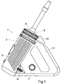
- FIG. 1 1 shows an exemplary embodiment of a hot air extraction inhaler 1 according to the invention with an inhaler housing 2, in which a heat exchanger 3 which is thermally insulated towards the inhaler housing 2 is shown.
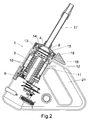
- FIG. 2 to the Heating an air flow is arranged.
- an inhaler outlet 4 of the hot air extraction inhaler 1 is subjected to negative pressure, that is to say, for example, when air is inhaled from the hot air extraction inhaler 1 through the inhaler outlet 4
- the heat exchanger 3 is electrically heated, wherein the temperature with a temperature selector 6 selectable and the supply voltage via a mains voltage switch 7 is switchable.
- FIG. 2 shows the interior of the inhaler housing 2 in an axial sectional view.
- the inhaler housing 2 As essential parts, the inhaler housing 2, the heat exchanger 3 and a filling chamber 8 for aerosol-forming substances under heat, which is arranged in the flow direction in extension of the heat exchanger 3 between the Inhalatorauslass 4 and the heat exchanger 3.
- the heat exchanger 3 has a central electric heating cartridge 9 and two coiled air ducts 10 which are peripherally closed on the outside of an outer tube 11.
- the outer tube 11 is surrounded by an insulating jacket 12 for thermal insulation of the heat exchanger 3 relative to the inhaler housing 2.
- the heating cartridge 9 and the heat exchanger 3, together with the outer tube 11, form a heater of the hot air extraction inhaler 1.
- the filling chamber 8 has an inner chamber housing 13 with a chamber bottom 14 and the inhaler outlet 4 with a chamber lid 15, wherein the inhaler outlet 4 for filling and emptying the filling chamber 8 of the outer chamber housing 18 is releasable.
- the filling chamber 8 is arranged coaxially with the heat exchanger 3 and guided in the axial direction in the inhaler housing 2 axially movable.
- the filling chamber 8 is removable by means of a thermally insulating actuating lever 16.
- the inhaler outlet 4 is bell-shaped and has a heat-insulating design.
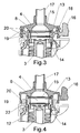
- FIG. 3 shows an enlarged detail of the inhaler outlet 4 facing the end of the heat exchanger 3 and the flow direction then arranged in the filling chamber 8 with the following inhaler 4. clearer than in the FIG. 2 the filling chamber 8 with the inner chamber housing 13, the outer chamber housing 18, the chamber bottom 14 and the chamber lid 15 can be seen.
- the filling chamber 8 can be opened by removing the inhaler outlet 4 together with the suction tube 17 and the chamber lid 15 from the inner and outer chamber housings 13 and 18.
- the FIG. 3 shows the inner chamber housing 13 end face in contact with the heat exchanger 3, wherein a direct thermal contact between the heated heat exchanger 3 and the inner chamber housing 13 is made, so that the inner chamber housing 13 heated by heat conduction and located in the filling chamber 8, in the drawing not shown aerosol forming substance by means of thermal radiation, starting from the inner chamber housing 13 is heated.
- the filling chamber 8 can be removed in this preferred embodiment for convenient emptying, cleaning and filling in the axial direction of the heat exchanger 3.
- the chamber housing 13 is rotated by means of the radially projecting actuating lever 16, which engages the outer chamber housing 18, relative to the heat exchanger 3 and the inhaler housing 2 in the circumferential direction of the filling chamber 8.
- the inner chamber housing 13 has a positive and / or non-positively connected outer chamber housing 18, on which the actuating lever 16 is formed and thus rotatably connected.
- the outer chamber housing 18, which surrounds the inner chamber housing 13, has a thread 19 on the outer peripheral side facing the inhaler housing 2, which thread is formed in the illustrated embodiment by helical vanes.
- the helical wings act with an associated Internal thread 20 in the inhaler housing 2 together.
- the filling chamber 8 moves toward or away from the heat exchanger 3.
- FIG. 4 also shows a section of the inhaler outlet 4 facing the end of the heat exchanger 3 and arranged in the flow direction then filling chamber 8 with the following inhaler 4.
- FIG. 4 shows the FIG. 4 an integrated in the heat exchanger 3 inner chamber housing 13 of the filling chamber 8.
- the heat exchanger 3 and the inner chamber housing 13 here form a common, integrally executed part.
- the outer chamber housing 18 is omitted FIG. 4 and is replaced by a protective cylinder 22 which is made together with the insulating jacket 12 together in one piece.
- the actuating lever 16 is embodied here in one piece with the inhaler outlet 4.
- the filling chamber 8 can be opened by removing the inhaler outlet 4 together with the suction hose 17 and the chamber lid 15 from the inner chamber housing 13.
- the FIG. 4 shows the inner chamber housing 13 together as one piece with the heat exchanger 3, wherein a direct thermal connection between the heated heat exchanger 3 and the inner chamber housing 13, so that the inner chamber housing 13 is heated by heat conduction and located in the filling chamber 8, in the drawing, not shown aerosol forming substance by means of thermal radiation, starting from the inner chamber housing 13 and partly heated by the heat exchanger 3.
- the inhaler outlet 4 can be removed in this embodiment in the axial direction of the filling chamber 8.
- the inhaler outlet 4 is rotated relative to the heat exchanger 3 and the inhaler housing 2 in the circumferential direction of the filling chamber 8 by means of the radially projecting actuating lever 16, which acts on the inhaler outlet 4.
- the inhaler outlet 4 is connected to the Actuator 16 rotatably connected.
- the inhaler outlet 4 has, on the outer peripheral side directed toward the inhaler housing 2, a thread 19, which in the illustrated embodiment is formed by helical blades.
- the spiral vanes 19 cooperate with an associated internal thread 20 in the inhaler housing 2.
- the filling chamber 8 moves toward or away from the heat exchanger 3.
- the in the FIGS. 1 to 4 illustrated hot air extraction inhaler 1 according to the invention is preferably used as a stand-alone and as a hand-held device.
- the inhaler housing 2 is designed in the manner of a hand-held device with a handle 21 on one side of the inhaler housing 2.
Description
Die Erfindung betrifft einen Heißluftextraktionsinhalator, mit einer Heizung zur Erwärmung von unter Wärmeeinwirkung aerosolbildende Substanzen die von Luft durchströmt in die Luft übergehen und entweder über einen Zwischenspeicher oder direkt aus dem Inhalator über eine Inhalationsleitung mit Mundstück heraus inhaliert werden.The invention relates to a Heißluftextraktionsinhalator, with a heater for heating under heat aerosol forming substances passing through the air pass into the air and inhaled either via a buffer or directly from the inhaler via an inhalation line with mouthpiece out.
Derartige therapeutische Verdampfungsvorrichtungen zur Erzeugung von Aroma- und/oder Wirkstoffdämpfen für die Inhalation sind aus dem Stand der Technik in vielfältigen Ausführungsformen bekannt. Beispielhaft wird auf die Patentschriften
Einfache Heißluftextraktionsinhalatoren verfügen lediglich über eine beheizte Füllkammer zur Erwärmung der zu verdampfenden Substanzen mittels Wärmestrahlung. Diese Bauweise ist kostengünstig, ermöglicht aber nur eine unzureichende Verdampfung, da während der Inhalation die nachströmende unbeheizte Luft die Füllkammer und die darin enthaltenen Substanzen wieder abkühlt und dadurch den Verdampfungsvorgang unterbricht. Es muss dann gewartet werden bis die Strahlungswärme der Füllkammer die enthaltenen Substanzen wieder für die Verdampfung hinreichend erwärmt hat. Heißluftextraktionsinhalatoren, die lediglich mit Wärmestrahlung arbeiten, eignen sich allenfalls für die Verdampfung von Reinstoffen, für die Verdampfung von Aromen und Wirkstoffen aus Heilkräutern sind sie nur eingeschränkt nutzbar.Simple Heißluftextraktionsinhalatoren have only a heated filling chamber for heating the substances to be evaporated by means of thermal radiation. This design is inexpensive, but allows only insufficient evaporation, since during inhalation, the inflowing unheated air cools the filling chamber and the substances contained therein again, thereby interrupting the evaporation process. It must then be maintained until the radiant heat of the filling chamber contained Substances has heated sufficiently for evaporation again. Hot air extraction inhalers, which only work with thermal radiation, are suitable at most for the evaporation of pure substances, for the evaporation of flavors and active ingredients from medicinal herbs, they are only limited use.
Wesentlich ergiebiger ist die Methode, bei der die Substanzen mit einem heißem Luftstrom beaufschlagt werden, der beim Passieren eines Wärmeerzeugers aufgeheizt wird. Die Heißluft durchströmt die Füllkammer mit den Substanzen, wobei die Substanzen verdampfen oder ihre Wirkstoffe wie z.B. bei Heilkräutern aus einem Substrat heraus ausdünsten (extrahieren), die dann in die Heißluft übergehen. Diese zum Beispiel mit Aromen und/oder Wirkstoffen befrachtete Heißluft wird als Einatemluft inhaliert, nachdem sie auf eine zum Einatmen angenehme Temperatur heruntergekühlt wurde, wobei die Wirkstoffe nach dem Inhalieren über die Lunge in den Blutkreislauf gelangen. Für die Heißluftextraktion werden häufig Heilkräuter oder andere geeignete pflanzliche Substanzen verwendet, die dem Verwendungszweck entsprechend angemessen zerkleinert sind oder aber auch synthetische Substanzen mit therapeutischen Wirkstoffen, die in pulverisierter Form vorliegen. Es können auch flüssige Substanzen verdampft werden. Zur Aerosolbildung müssen diese Substanzen mit Heißluft von beispielsweise 200° C beaufschlagt werden. Einen Verdampfer, der in einem Wärmetauscher Heißluft erzeugt, die durch eine Füllkammer hindurchgeführt wird und in der Füllkammer enthaltene Substanzen erwärmt, offenbart die Europäische Patentanmeldung
Die europäische Patentanmeldung
Bei der effektiveren Methode der Lufterwärmung wird üblicherweise ein Wärmeerzeuger verwendet, der mindestens einen Luftkanal für den zu erwärmenden Luftstrom aufweist. Der Luftkanal kann den Wärmeerzeuger innen durchsetzen oder außen einschließen. Es gibt auch Ausführungen, bei denen elektrische Heizdrähte offen im Luftkanal angebracht sind. Prinzipiell gibt es bei bekannten gattungsgemäßen Heißluftextraktionsinhalatoren zwei Grundprinzipien zur Erzeugung des heißen Luftstroms mittels des Wärmeerzeugers. Zum einen kann der Luftstrom durch Ansaugen von Luft an einer Austrittsöffnung oder zum anderen durch Einblasen von Luft in eine Eintrittsöffnung des Luftkanals erzeugt werden, wobei der erforderliche Über- bzw. Unterdruck mittels Lungenkraft oder unter Verwendung eines Gebläses oder einer Pumpe, beispielsweise einer Membranpumpe, aufgebaut werden kann. Durch den thermischen Kontakt mit dem Wärmeerzeuger wird die an einem Inhalatoreinlass in den Luftkanal einströmende Umgebungsluft in Abhängigkeit von der von dem Wärmeerzeuger ausgehenden Temperatur und dem Volumenstrom durch den Luftkanal von Zimmertemperatur auf beispielsweise 200° C erwärmt. Die Temperatur ist abgestimmt auf den Siede- oder Extraktionspunkt der für die Inhalation verwendeten aerosolbildenden Substanzen, so dass deren Wirkstoffe und/oder Aromen beim Durchtritt des Heißluftstroms durch die Füllkammer verdampfen und die Aerosole von dem Luftstrom aufgenommen werden. Nach dem Passieren der Füllkammer mit den aerosolbildenden Substanzen steht der aerosolbefrachtete Luftstrom als Einatemluft zur Inhalation zur Verfügung.In the more effective method of air heating, a heat generator is usually used which has at least one air channel for the air flow to be heated. The air duct can pass through the heat generator inside or outside. There are also versions in which electric heating wires are mounted open in the air duct. In principle, there are two basic principles for generating the hot air flow by means of the heat generator in known generic Heißluftextraktionsinhalatoren. On the one hand, the air flow can be generated by suction of air at an outlet opening or the other by blowing air into an inlet opening of the air duct, wherein the required positive or negative pressure by means of lung power or using a blower or a pump, for example a Diaphragm pump, can be built. Due to the thermal contact with the heat generator, the ambient air flowing into the air duct at an inhaler inlet is heated from room temperature to, for example, 200 ° C. in dependence on the temperature emanating from the heat generator and the volume flow through the air duct. The temperature is adjusted to the boiling or extraction point of the aerosol-forming substances used for the inhalation, so that their active ingredients and / or flavors evaporate as the hot air flow passes through the filling chamber and the aerosols are taken up by the air flow. After passing through the filling chamber with the aerosol-forming substances, the aerosol-laden air stream is available as inhaled air for inhalation.
Zunächst aber muss der heiße Luftstrom sowohl die kalten Substanzen als auch die kalte umgebende Füllkammer aufheizen, damit eine Verdampfung dieser Substanzen überhaupt stattfinden kann.First, however, the hot air stream must heat both the cold substances and the cold surrounding filling chamber, so that evaporation of these substances can take place at all.
Bei Verwendung eines Heißluftextraktionsinhalators mit Pumpe und Zwischenspeicher, beispielsweise eines Kunststoffinhalationsbeutels wie in
Im Unterschied dazu ergibt sich bei Verwendung eines Heißluftextraktionsinhalators mit Heißluftstrom, bei dem direkt aus dem Inhalator heraus inhaliert bzw. angesaugt wird, das Problem, dass zunächst einige Atemzüge benötigt werden, um sowohl die kalten Substanzen als auch die kalte umgebende Füllkammer mittels Heißluftstrom aufzuheizen, da vorher keine Verdampfung stattfinden kann. Dies ist für den Anwender nicht nur unkomfortabel, er weiß auch nicht genau wann die Verdampfung einsetzt.In contrast, when using a hot air extraction inhaler with hot air flow that inhales or aspirates directly out of the inhaler, there is the problem that first several breaths are needed to heat both the cold substances and the cold surrounding filling chamber by means of hot air flow, since no evaporation can take place beforehand. This is not only uncomfortable for the user, he also does not know exactly when the evaporation starts.
Ausgehend von dem Stand der Technik liegt der Erfindung die Aufgabe zugrunde, eine Möglichkeit vorzuschlagen, wie der Anwender von Heißluftextraktionsinhalatoren, bei denen direkt aus dem Inhalator heraus inhaliert wird, möglichst sofort mit dem ersten Inhalationszug und dann andauernd Aroma- und wirkstoffreiche Dämpfe erhalten kann.Based on the prior art, the present invention seeks to propose a way in which the user of Heißluftextraktionsinhalatoren where inhaled directly from the inhaler out, as soon as possible with the first inhalation and then constantly flavor and drug-rich vapors.
Diese Aufgabe wird erfindungsgemäß durch einen Heißluftexktrationsinhalator mit den Merkmalen des Anspruchs 1 gelöst. Weitere vorteilhafte Ausgestaltungen sind den Unteransprüchen zu entnehmen.This object is achieved by a Heißluftexktrationsinhalator with the features of
Kerngedanke der Erfindung ist es, die Heizung von Heißluftextraktionsinhalatoren so zu verbessern, dass sowohl eine sofortige, als auch während des Inhalationszuges andauernde Verdampfung stattfinden kann.The core idea of the invention is to improve the heating of hot air extraction inhalers so that both an immediate, as well as during the inhalation train continuous evaporation can take place.
Danach weist der erfindungsgemäße Heißluftexktrationsinhalator eine Heizung auf, die sowohl eine Füllkammer mit Inhalt beheizt, als auch in der Lage ist, einen heißen Luftstrom zu erzeugen, welcher durch die Füllkammer mit Inhalt hindurchgeführt wird. Dazu weist die Heizung, die als massiver Wärmetauscher mit einem oder mehreren durchgeführten Luftkanälen ausgeführt sein kann, vorzugsweise in einer Ausführungsform eine im Wärmetauscher integrierte Füllkammer und in einer anderen bevorzugten Ausführungsform eine abnehmbare, aber in aufgesetztem Zustand über eine Kontaktfläche thermisch mit dem Wärmetauscher verbundene Füllkammer auf. Die Innenwand der Füllkammer ist in beiden Fällen so ausgebildet, dass der Füllkammerinhalt mittels Strahlungswärme aufgeheizt wird. Die beheizte Innenwand der Füllkammer erwärmt ihren Inhalt durch Strahlungswärme und am Rand durch thermischen Kontakt des Inhalts mit der Innenwand der Füllkammer unabhängig davon, ob Heißluft durch die Füllkammer strömt oder nicht. Die Beheizung der Füllkammer reicht aus, um in ihr enthaltene Substanzen auf eine zur aerosolbildende Temperatur zu erwärmen und auf dieser Temperatur zu halten, wenn die Füllkammer nicht von Luft durchströmt wird. Wird die Füllkammer von Luft durchströmt, ist diese zuvor aufgeheizt worden, so dass sie den Inhalt der Füllkammer nicht kühlt, sondern auf der zur aerosolbildenden Temperatur hält bzw. gemeinsam mit der Füllkammer auf diese Temperatur erwärmt.Thereafter, the Heißluftexktrationsinhalator invention has a heater that heats both a filling chamber with content, as well as is able to generate a hot air flow, which is passed through the filling chamber with content. For this purpose, the heater, which may be designed as a solid heat exchanger with one or more performed air ducts, preferably in one embodiment a filling chamber integrated in the heat exchanger and in another preferred embodiment a removable, but in an attached state via a contact surface thermally connected to the heat exchanger filling chamber on. The inner wall of the filling chamber is formed in both cases so that the Füllkammerinhalt is heated by radiant heat. The heated inner wall of the filling chamber heats its contents by radiant heat and at the edge by thermal contact of the contents with the inner wall of the filling chamber, regardless of whether hot air flows through the filling chamber or not. The heating of the filling chamber is sufficient to heat substances contained in it to a temperature which is formed at the aerosol and to keep it at this temperature, when the filling chamber is not traversed by air. If the filling chamber is traversed by air, this has been previously heated, so that they are the contents of Filling chamber does not cool, but keeps on the aerosol-forming temperature or heated together with the filling chamber to this temperature.
Auch wenn die Erfindung auf Heißluftextraktionsinhalatoren zur direkten Inhalation eines Anwenders gerichtet ist, ist sie nicht auf solche Heißluftexktrationsinhalatoren beschränkt sondern allgemein auf gattungsgemäße Heißluftextraktionsinhalatoren gerichtet. Die Erfindung ist beispielsweise auch für Heißluftextraktionsinhalatoren von Vorteil, die einen Zwischenspeicher, in den das Aerosol/Luftgemisch zunächst gepumpt und aus dem dann später heraus inhaliert wird, aufweisen.Although the invention is directed to hot air extraction inhalers for direct inhalation of a user, it is not limited to such hot air inhalation inhalers but is generally directed to generic hot air extraction inhalers. The invention is also advantageous, for example, for hot air extraction inhalers, which have a buffer in which the aerosol / air mixture is first pumped and then inhaled later out of it.
Die Füllkammer besteht aus einem inneren, gut wärmeleitendem Teil aus z.B. Metall, das insbesondere die Innenwand der Füllkammer bzw. ein inneres Kammergehäuse bildet, und einem äußeren, gut wärmeisolierendem umlaufenden Teil aus z.B. Kunststoff. Bei der im Wärmetauscher integrierten Füllkammer ist das innere Kammergehäuse Bestandteil des Wärmetauschers.The filling chamber consists of an inner, good heat conducting part of e.g. Metal, which in particular forms the inner wall of the filling chamber or an inner chamber housing, and an outer, good heat-insulating circumferential part made of e.g. Plastic. With the filling chamber integrated in the heat exchanger, the inner chamber housing is part of the heat exchanger.
Bei der abnehmbaren Füllkammer ist das wärmeleitende innere Kammergehäuse zum Beispiel stirnseitig an dem Wärmetauscher anlegbar. Dies ermöglicht während des Aufheizvorgangs oder auch bei bereits aufgeheiztem Wärmetauscher einen schnellen Wärmeübergang von dem Wärmetauscher zu dem inneren Kammergehäuse mittels direkter Wärmeleitung. Dabei besteht das innere Kammergehäuse, das die Füllkammer für die zu verdampfenden Substanzen umgibt und begrenzt, aus einem gut wärmeleitenden Material wie z. B. Metall.In the removable filling chamber, the heat-conducting inner chamber housing, for example, frontally applied to the heat exchanger. This allows during the heating or even in already heated heat exchanger rapid heat transfer from the heat exchanger to the inner chamber housing by means of direct heat conduction. In this case, there is the inner chamber housing, which surrounds the filling chamber for the substances to be evaporated and limited, from a good heat conducting material such. Metal.
Bei im Wärmetauscher integriertem oder anliegendem inneren Kammergehäuse trocknen in der Füllkammer aufgenommene feuchte Substanzen, beispielsweise Pflanzenmaterial, bevor mit der Inhalation begonnen wird noch während der Aufheizphase. Das Wasser in dem Pflanzenmaterial verdunstet dadurch in kurzer Zeit, typischerweise in weniger als einer Minute: Nach dem Trocknen des Pflanzenmaterials kann anschließend das Pflanzenmaterial oder allgemein die in der Füllkammer enthaltenen, durch Wärmeeinwirkung Aerosol bildenden Substanzen mittels dem durch Lungenkraft erzeugten Heißluftstrom aus dem Pflanzenmaterial freigesetzt und von der Einatemluft aufgenommen werden. Solange Feuchtigkeit in den Substanzen enthalten ist, verhindert sie eine Erwärmung über den Siedepunkt des Wassers. Feuchtigkeit verhindert die Erwärmung der Substanzen auf die zur Aerosolbildung notwendige Temperatur.When integrated in the heat exchanger or adjacent inner chamber housing dry in the filling chamber absorbed moist substances, such as plant material, before the inhalation is started during the heating phase. The water in the plant material thereby evaporates in a short time, typically in less than a minute: after drying of the plant material, the plant material or, generally, the aerosol formed by the action of heat in the filling chamber can then be formed Substances are released from the plant material by means of the hot air flow generated by lung force and absorbed by the inhaled air. As long as moisture is contained in the substances, it prevents heating above the boiling point of the water. Moisture prevents the heating of the substances to the temperature necessary for aerosol formation.
In einer bevorzugten Ausführungsform der Erfindung ist das innere Kammergehäuse zylindrisch ausgebildet und axial bewegbar in dem Inhalatorgehäuse geführt. Dies ist insbesondere dann von Vorteil, wenn der Wärmetauscher ebenfalls eine im Wesentlichen zylinderförmige Kontur aufweist. Damit kann das innere Kammergehäuse mit der Füllkammer auf einfache Weise stirnseitig und koaxial zu dem Luftkanal an dem Wärmetauscher derart angeordnet werden, dass der aus dem Wärmetauscher austretende Luftstrom durch Luftdurchtrittsöffnungen in einem Boden und einem Deckel der Füllkammer durch die darin befindlichen für Heißluftextraktion vorgesehenen Substanzen geleitet werden kann. Der Boden und/oder der Deckel der Füllkammer kann auch in üblicher Weise von einem metallischen Drahtgeflecht gebildet sein.In a preferred embodiment of the invention, the inner chamber housing is cylindrical and guided axially movable in the inhaler housing. This is particularly advantageous if the heat exchanger also has a substantially cylindrical contour. Thus, the inner chamber housing can be arranged with the filling chamber in a simple manner end face and coaxial with the air duct on the heat exchanger such that the exiting the heat exchanger air flow passed through air passage openings in a bottom and a lid of the filling chamber through the therein provided for hot air extraction substances can be. The bottom and / or the lid of the filling chamber can also be formed in the usual way by a metallic wire mesh.
In einer vorteilhaften Ausführungsform des erfindungsgemäßen Heißluftextraktionsinhalators weist die abnehmbare Füllkammer umfangsseitig ein Gewinde auf, das mit einem Gegengewinde des Inhalatorgehäuses zusammen wirkt. Das Gewinde kann an einem Innenumfang oder an einem Außenumfang der Füllkammer ausgebildet sein, wobei das Gegengewinde des Inhalatorgehäuses jeweils komplementär dazu ausgebildet und korrespondierend dazu angeordnet ist. Das Drehen der Füllkammer gegenüber dem Inhalatorgehäuse des Heißluftextraktionsinhalators bewirkt abhängig von der Drehrichtung einen guten Kraftschluss und damit eine gute Dichtigkeit des inneren Kammergehäuses zu dem Wärmetauscher. Dasselbe gilt für den Füllkammerdeckel, welcher unabhängig von integrierter oder abnehmbarer Füllkammer in derselben Weise mit der Füllkammer verbunden wird.In an advantageous embodiment of the hot air extraction inhaler according to the invention, the removable filling chamber has a thread on the circumference which interacts with a mating thread of the inhaler housing. The thread may be formed on an inner circumference or on an outer circumference of the filling chamber, wherein the mating thread of the inhaler housing is in each case formed complementary thereto and arranged corresponding thereto. The rotation of the filling chamber relative to the inhaler housing of the Heißluftextraktionsinhalators causes depending on the direction of rotation a good adhesion and thus a good tightness of the inner chamber housing to the heat exchanger. The same applies to the filling chamber lid, which is connected to the filling chamber in the same way regardless of the integrated or removable filling chamber.
Des Weiteren weist das äußere Kammergehäuse in einer bevorzugten Ausführungsform der Erfindung einen thermisch isolierenden Betätigungshebel zum Drehen des Kammergehäuses bzw. der Füllkammer gegenüber dem Inhalatorgehäuse auf. Damit werden Verbrennungen beim Abnehmen bzw. Aufsetzen der Füllkammer zu dem aufgeheizten Wärmetauscher sicher vermieden.Furthermore, in a preferred embodiment of the invention, the outer chamber housing has a thermally insulating actuating lever for rotating the chamber housing or the filling chamber relative to the inhaler housing. This burns when removing or placing the filling chamber are reliably avoided to the heated heat exchanger.
Bei einer zweckmäßigen Ausführungsform des erfindungsgemäßen Heißluftextraktionsinhalators ist das Inhalatorgehäuse nach Art eines Handgerätes mit einem Griff ausgebildet. Dabei kann ein den Wärmetauscher umschließender Inhalatorgehäusebereich als Griff ausgebildet sein oder das Inhalatorgehäuse weist einen seitlich angeordneten Griff auf.In an expedient embodiment of the hot air extraction inhaler according to the invention, the inhaler housing is designed in the manner of a hand-held device with a handle. In this case, an inhaler housing area enclosing the heat exchanger can be designed as a handle or the inhaler housing has a laterally arranged handle.
Nachfolgend wird die Erfindung anhand eines in der Zeichnung dargestellten Ausführungsbeispiels näher erläutert. Weitere Merkmale der Erfindung ergeben sich aus der folgenden Beschreibung des Ausführungsbeispiels der Erfindung in Verbindung mit den Ansprüchen und der beigefügten Zeichnung. Die einzelnen Merkmale können für sich allein oder zu mehreren bei unterschiedlichen Ausführungsformen der Erfindung verwirklicht sein. Es zeigen:
Figur 1- einen erfindungsgemäßen Heißluftextraktionsinhalator mit abnehmbarer Füllkammer in Seitenansicht;
Figur 2- den
Heißluftextraktionsinhalator gemäß Figur 1 in einer Achsschnittdarstellung; Figur 3- den
Inhalatorauslass aus Figur 2 in einer Ausschnittsvergrößerung. und Figur 4- einen Inhalatorauslass mit integrierter Füllkammer in einer Ausschnittsvergrößerung
- FIG. 1
- a hot air extraction inhaler according to the invention with removable filling chamber in side view;
- FIG. 2
- the hot air extraction inhaler according to
FIG. 1 in an axial section representation; - FIG. 3
- the inhaler outlet off
FIG. 2 in a detail enlargement. and - FIG. 4
- an inhaler outlet with integrated filling chamber in an enlarged detail
Die
Die Füllkammer 8 weist ein inneres Kammergehäuse 13 mit einem Kammerboden 14 und den Inhalatorauslass 4 mit einem Kammerdeckel 15 auf, wobei der Inhalatorauslass 4 zum Befüllen und zum Entleeren der Füllkammer 8 von dem äußeren Kammergehäuse 18 lösbar ist. Die Füllkammer 8 ist koaxial zu dem Wärmetauscher 3 angeordnet und in axialer Richtung in dem Inhalatorgehäuse 2 axial bewegbar geführt. Die Füllkammer 8 ist mittels einem thermisch isolierenden Betätigungshebel 16 abnehmbar. Der Inhalatorauslass 4 ist glockenförmig und wärmeisolierend ausgebildet. Er trägt den Kammerdeckel 15, der genau wie der Kammerboden 14 luftdurchlässig ausgeführt, beispielsweise perforiert ist, und einen aus dem Inhalatorgehäuse 2 vorstehenden Saugschlauch 17 zum Einatmen von Luft aus dem Heißluftextraktionsinhalator 1 (Inhalieren) aufweist.The filling
Die
Die Füllkammer 8 ist durch Abnehmen des Inhalatorauslasses 4 zusammen mit dem Saugschlauch 17 und dem Kammerdeckel 15 von dem inneren und äußeren Kammergehäuse 13 und 18 öffenbar. Die
Die Füllkammer 8 kann in dieser bevorzugten Ausführungsform zur bequemeren Entleerung, Reinigung und Befüllung in axialer Richtung von dem Wärmetauscher 3 abgenommen werden. Dazu wird das Kammergehäuse 13 mittels des radial abstehenden Betätigungshebels 16, der an dem äußeren Kammergehäuse 18 angreift, gegenüber dem Wärmetauscher 3 und dem Inhalatorgehäuse 2 in Umfangsrichtung der Füllkammer 8 gedreht werden. Das innere Kammergehäuse 13 weist ein form- und/oder kraftschlüssig verbundenes äußere Kammergehäuse 18 auf, an dem der Betätigungshebel 16 angeformt und damit drehfest verbunden ist. Das äußere Kammergehäuse 18, welches das innere Kammergehäuse 13 umgreift, weist auf der zum Inhalatorgehäuse 2 gerichteten Außenumfangsseite ein Gewinde 19 auf, das bei dem dargestellten Ausführungsbeispiel von Wendelflügeln gebildet ist. Die Wendelflügel wirken mit einem zugeordneten Innengewinde 20 im Inhalatorgehäuse 2 zusammen. Abhängig von einer Bewegungsrichtung des Betätigungshebels 16 in oder entgegen dem Uhrzeigersinn bewegt sich die Füllkammer 8 zu dem Wärmetauscher 3 hin oder von ihm weg.The filling
Die
Die Füllkammer 8 ist durch Abnehmen des Inhalatorauslasses 4 zusammen mit dem Saugschlauch 17 und dem Kammerdeckel 15 von dem inneren Kammergehäuse 13 öffenbar. Die
Der Inhalatorauslass 4 kann in dieser Ausführungsform in axialer Richtung von der Füllkammer 8 abgenommen werden. Dazu wird der Inhalatorauslass 4 mittels des radial abstehenden Betätigungshebels 16, der an dem Inhalatorauslass 4 angreift, gegenüber dem Wärmetauscher 3 und dem Inhalatorgehäuse 2 in Umfangsrichtung der Füllkammer 8 gedreht. Der Inhalatorauslass 4 ist mit dem Betätigungshebel 16 drehfest verbunden. Der Inhalatorauslass 4 weist auf der zum Inhalatorgehäuse 2 gerichteten Außenumfangsseite ein Gewinde 19 auf, das bei dem dargestellten Ausführungsbeispiel von Wendelflügeln gebildet ist. Die Wendelflügel 19 wirken mit einem zugeordneten Innengewinde 20 im Inhalatorgehäuse 2 zusammen. Abhängig von einer Bewegungsrichtung des Betätigungshebels 16 in oder entgegen dem Uhrzeigersinn bewegt sich die Füllkammer 8 zu dem Wärmetauscher 3 hin oder von ihm weg.The
Der in den
Claims (9)
- A hot air extraction inhaler (1) including a heat exchanger (3), which is able to produce a hot air current, a filling chamber (8) for filling with substances which form an aerosol under the influence of heat, through which the hot air current from the heat exchanger is conducted, and including an inhaler outlet (4) for the inhalation of the aerosol/air mixture, characterised in that the filling chamber (8) includes an inner chamber housing (13) of a good thermally conductive material and that a heat exchanger (3) is used which not only is able to produce the hot air current but also heats the inner chamber housing (13) directly by thermal conduction so that the filling chamber (8) heats its contents by means of radiant heat.
- A hot air extraction inhaler as claimed in Claim 1, characterised in that the inner chamber housing (13) of the filling chamber (8) is integrally permanently integrated into the heat exchanger.
- A hot air extraction inhaler as claimed in Claim 1, characterised in that the filling chamber (8) with the inner chamber housing (13) is constructed to be removable from the heat exchanger (3) and the inner chamber housing (13) is thermally conductively connected to the heat exchanger (3) in the fitted condition.
- A hot air extraction inhaler as claimed in Claim 3, characterised in that the inner chamber housing (13) of the filling chamber (8) is selectively mountable on the end surface of the heat exchanger (3).
- A hot air extraction inhaler as claimed in Claims 3 and 4, characterised in that the filling chamber (8) is of cylindrical construction and is guided so as to be axially movable in the inhaler housing (2).
- A hot air extraction inhaler as claimed in Claims 3 to 5, characterised in that the filling chamber (8) has on its periphery a screw thread (19), which cooperates with a screw thread (20) on the inhaler housing (2).
- A hot air extraction inhaler as claimed in Claims 3 to 6, characterised in that the filling chamber (8) includes a thermally insulating actuating lever (16) for rotation with respect to the inhaler housing (2) and the heat exchanger (3).
- A hot air extraction inhaler as claimed in one of the preceding claims, characterised in that an inhaler outlet (4) is removably connected to the inner chamber housing (13).
- A hot air extraction inhaler as claimed in one of the preceding claims, characterised in that an inhaler housing (2) is constructed in the manner of a handheld unit with a handle (21).
Priority Applications (4)
| Application Number | Priority Date | Filing Date | Title |
|---|---|---|---|
| EP11401648.8A EP2599512B1 (en) | 2011-12-01 | 2011-12-01 | Warm air extraction inhaler with combined air and radiant heating |
| ES11401648.8T ES2577828T3 (en) | 2011-12-01 | 2011-12-01 | Hot air extraction inhaler equipped with a combined heating of air and radiation |
| US13/687,545 US9272103B2 (en) | 2011-12-01 | 2012-11-28 | Vaporizer with combined air and radiation heating |
| CA2797897A CA2797897C (en) | 2011-12-01 | 2012-11-30 | Vaporizer with combined air and radiation heating |
Applications Claiming Priority (1)
| Application Number | Priority Date | Filing Date | Title |
|---|---|---|---|
| EP11401648.8A EP2599512B1 (en) | 2011-12-01 | 2011-12-01 | Warm air extraction inhaler with combined air and radiant heating |
Publications (2)
| Publication Number | Publication Date |
|---|---|
| EP2599512A1 EP2599512A1 (en) | 2013-06-05 |
| EP2599512B1 true EP2599512B1 (en) | 2016-05-11 |
Family
ID=45346396
Family Applications (1)
| Application Number | Title | Priority Date | Filing Date |
|---|---|---|---|
| EP11401648.8A Active EP2599512B1 (en) | 2011-12-01 | 2011-12-01 | Warm air extraction inhaler with combined air and radiant heating |
Country Status (4)
| Country | Link |
|---|---|
| US (1) | US9272103B2 (en) |
| EP (1) | EP2599512B1 (en) |
| CA (1) | CA2797897C (en) |
| ES (1) | ES2577828T3 (en) |
Families Citing this family (44)
| Publication number | Priority date | Publication date | Assignee | Title |
|---|---|---|---|---|
| US20160345631A1 (en) | 2005-07-19 | 2016-12-01 | James Monsees | Portable devices for generating an inhalable vapor |
| US10517530B2 (en) | 2012-08-28 | 2019-12-31 | Juul Labs, Inc. | Methods and devices for delivering and monitoring of tobacco, nicotine, or other substances |
| US10279934B2 (en) | 2013-03-15 | 2019-05-07 | Juul Labs, Inc. | Fillable vaporizer cartridge and method of filling |
| IL297399B2 (en) | 2013-05-06 | 2024-02-01 | Juul Labs Inc | Nicotine salt formulations for aerosol devices and methods thereof |
| WO2014201432A1 (en) | 2013-06-14 | 2014-12-18 | Ploom, Inc. | Multiple heating elements with separate vaporizable materials in an electric vaporization device |
| US9854843B2 (en) | 2013-08-08 | 2018-01-02 | Haze Industries, Inc. | Vaporizer |
| EP3076805A4 (en) | 2013-12-05 | 2017-10-11 | PAX Labs, Inc. | Nicotine liquid formulations for aerosol devices and methods thereof |
| US10159282B2 (en) | 2013-12-23 | 2018-12-25 | Juul Labs, Inc. | Cartridge for use with a vaporizer device |
| US9549573B2 (en) | 2013-12-23 | 2017-01-24 | Pax Labs, Inc. | Vaporization device systems and methods |
| PT3086671T (en) | 2013-12-23 | 2019-01-23 | Juul Labs Uk Holdco Ltd | Vaporization device systems |
| USD842536S1 (en) | 2016-07-28 | 2019-03-05 | Juul Labs, Inc. | Vaporizer cartridge |
| USD825102S1 (en) | 2016-07-28 | 2018-08-07 | Juul Labs, Inc. | Vaporizer device with cartridge |
| US20160366947A1 (en) | 2013-12-23 | 2016-12-22 | James Monsees | Vaporizer apparatus |
| US10076139B2 (en) | 2013-12-23 | 2018-09-18 | Juul Labs, Inc. | Vaporizer apparatus |
| US10058129B2 (en) | 2013-12-23 | 2018-08-28 | Juul Labs, Inc. | Vaporization device systems and methods |
| US10238764B2 (en) | 2014-08-19 | 2019-03-26 | Vapium Inc. | Aromatherapy vaporization device |
| US11065402B2 (en) | 2014-02-04 | 2021-07-20 | Gseh Holistic, Inc. | Aromatherapy vaporization device |
| KR102650793B1 (en) * | 2014-02-10 | 2024-03-26 | 필립모리스 프로덕츠 에스.에이. | An aerosol-generating system having a fluid-permeable heater assembly |
| US11478021B2 (en) | 2014-05-16 | 2022-10-25 | Juul Labs, Inc. | Systems and methods for aerosolizing a vaporizable material |
| CN112155255A (en) | 2014-12-05 | 2021-01-01 | 尤尔实验室有限公司 | Corrective dose control |
| US20160353800A1 (en) * | 2015-06-08 | 2016-12-08 | Fernando Di Carlo | Dual-source vaporizer |
| BR112018016402B1 (en) | 2016-02-11 | 2023-12-19 | Juul Labs, Inc | SECURELY FIXED CARTRIDGES FOR VAPORIZER DEVICES |
| MX2018009702A (en) | 2016-02-11 | 2019-07-08 | Juul Labs Inc | Fillable vaporizer cartridge and method of filling. |
| US10405582B2 (en) | 2016-03-10 | 2019-09-10 | Pax Labs, Inc. | Vaporization device with lip sensing |
| USD849996S1 (en) | 2016-06-16 | 2019-05-28 | Pax Labs, Inc. | Vaporizer cartridge |
| MX2018015727A (en) | 2016-06-16 | 2019-05-16 | Juul Labs Inc | On-demand, portable convection vaporizer. |
| USD848057S1 (en) | 2016-06-23 | 2019-05-07 | Pax Labs, Inc. | Lid for a vaporizer |
| USD851830S1 (en) | 2016-06-23 | 2019-06-18 | Pax Labs, Inc. | Combined vaporizer tamp and pick tool |
| USD836541S1 (en) | 2016-06-23 | 2018-12-25 | Pax Labs, Inc. | Charging device |
| US11660403B2 (en) | 2016-09-22 | 2023-05-30 | Juul Labs, Inc. | Leak-resistant vaporizer device |
| USD887632S1 (en) | 2017-09-14 | 2020-06-16 | Pax Labs, Inc. | Vaporizer cartridge |
| US11632983B2 (en) | 2018-05-29 | 2023-04-25 | Juul Labs, Inc. | Vaporizer device body |
| EP3806679B1 (en) | 2018-06-15 | 2023-08-30 | Valley Product Concepts, LLC | Capsules for use in personal vaporizers |
| USD868368S1 (en) | 2018-06-15 | 2019-11-26 | Valley Product Concepts, LLC | Capsule for use in a personal vaporizer |
| USD869087S1 (en) | 2018-06-15 | 2019-12-03 | Valley Product Concepts, LLC | Capsule for use in a personal vaporizer |
| USD868367S1 (en) | 2018-06-15 | 2019-11-26 | Valley Product Concepts, LLC | Capsule for use in a personal vaporizer |
| WO2020051385A1 (en) | 2018-09-06 | 2020-03-12 | Bergstrom Sam | Vaporizer apparatuses and vaporizing methods |
| US11638802B2 (en) | 2019-01-30 | 2023-05-02 | David Vasconcelos | Chilled-air inhaler device and methods of using a chilled-air inhaler device for the alleviation of respiratory symptoms |
| US20220232893A1 (en) * | 2019-06-05 | 2022-07-28 | Canopy Growth Corporation | Convection and conduction vaporizer and method for operating the same |
| USD932687S1 (en) | 2019-09-17 | 2021-10-05 | Canopy Growth Corporation | Vaporizer |
| USD943808S1 (en) | 2019-10-29 | 2022-02-15 | Canopy Growth Corporation | Vaporizer |
| US11903427B2 (en) | 2019-12-19 | 2024-02-20 | John Robert Mumford | Aerosol-generating apparatus, thermal distribution casing, and related methods |
| USD950030S1 (en) | 2020-09-14 | 2022-04-26 | Valley Product Concepts, LLC | Capsule for use in a personal vaporizer |
| USD957727S1 (en) | 2021-01-25 | 2022-07-12 | Canopy Growth Corporation | Vaporizer |
Family Cites Families (13)
| Publication number | Priority date | Publication date | Assignee | Title |
|---|---|---|---|---|
| US3559886A (en) * | 1968-10-29 | 1971-02-02 | Mary Lee Howard | Portable steam generating unit |
| US4101611A (en) * | 1977-02-07 | 1978-07-18 | Amark Industries, Inc. | Nebulizer |
| US4114022A (en) * | 1977-08-16 | 1978-09-12 | Braulke Iii Herbert A | Combined hot air and steam hair dryer |
| US4699136A (en) * | 1983-12-22 | 1987-10-13 | Krauser Robert S | Method and apparatus for treating ailments |
| US4955372A (en) * | 1985-07-16 | 1990-09-11 | Transpirator Technologies, Inc. | Method and apparatus for pulmonary and cardiovascular conditioning of racehorses and competition animals |
| US5031612A (en) * | 1990-04-24 | 1991-07-16 | Devilbiss Health Care, Inc. | System and method for delivering warm humidified air |
| US6089857A (en) * | 1996-06-21 | 2000-07-18 | Japan Tobacco, Inc. | Heater for generating flavor and flavor generation appliance |
| US6250301B1 (en) * | 1997-08-28 | 2001-06-26 | Hortal Harm B.V. | Vaporizer for inhalation and method for extraction of active ingredients from a crude natural product or other matrix |
| DE19803376C1 (en) | 1998-01-29 | 1999-10-14 | Markus Storz | Inhaler for generating vapors containing aroma and / or active substances from plant material and / or liquids |
| DE10042396B4 (en) | 2000-08-29 | 2005-06-09 | Markus Storz | Hot air generation of hot air extraction inhalers |
| US6761164B2 (en) * | 2002-05-23 | 2004-07-13 | Shahin Amirpour | Herbal vaporizer |
| US8371310B2 (en) * | 2006-02-17 | 2013-02-12 | Jake Brenneise | Portable vaporizing device and method for inhalation and/or aromatherapy without combustion |
| ES2321468B1 (en) * | 2007-08-28 | 2010-07-07 | Jorge Fernandez Pernia | PORTABLE ESSENCE VAPORIZER. |
-
2011
- 2011-12-01 ES ES11401648.8T patent/ES2577828T3/en active Active
- 2011-12-01 EP EP11401648.8A patent/EP2599512B1/en active Active
-
2012
- 2012-11-28 US US13/687,545 patent/US9272103B2/en active Active
- 2012-11-30 CA CA2797897A patent/CA2797897C/en active Active
Non-Patent Citations (1)
| Title |
|---|
| None * |
Also Published As
| Publication number | Publication date |
|---|---|
| US9272103B2 (en) | 2016-03-01 |
| CA2797897C (en) | 2017-01-17 |
| US20130139813A1 (en) | 2013-06-06 |
| ES2577828T3 (en) | 2016-07-19 |
| CA2797897A1 (en) | 2013-06-01 |
| EP2599512A1 (en) | 2013-06-05 |
Similar Documents
| Publication | Publication Date | Title |
|---|---|---|
| EP2599512B1 (en) | Warm air extraction inhaler with combined air and radiant heating | |
| EP0582124B1 (en) | Atomizer device with heating element | |
| EP3110268B1 (en) | Smoking device | |
| DE4328243C1 (en) | Smoke or inhalation device | |
| EP0933093B1 (en) | Inhalator for aromatherapy | |
| DE3028130C2 (en) | Facial care device with application of moisture | |
| EP1884254B1 (en) | Breathing bag for inhalers | |
| EP0413127B1 (en) | Gas heating and humidification apparatus, especially for respiratory gases used in artificial respiration | |
| WO2017174754A1 (en) | Electronic cigarette with a tobacco-heating unit and an evaporator unit | |
| DE102005062185B3 (en) | Ventilation device with active dehumidification | |
| EP2599514A1 (en) | Hot air extraction inhaler with inhalation cooling line | |
| DE3045351A1 (en) | "NEBBLER AND ASSOCIATED HEATER" | |
| DE2516496C3 (en) | Device for humidifying the breathing gas | |
| WO1996034644A9 (en) | Method and device for producing respiratory air which is harmless to health in positive pressure nasal breathing apparatus | |
| DE202005008152U1 (en) | Condensation prevention device for active breathing gas humidification has breathing gas humidifier controller with adjustable element for regulating heating unit for heating exhaling valve/sensing arrangement | |
| DE102016125180A1 (en) | An evaporator unit for an inhaler and method for controlling an evaporator unit | |
| EP3908131A1 (en) | Apparatus and method for extracting and aspirating active substances, in particular from the cannabis plant | |
| AT502169B1 (en) | Pocket inhaler has external heating system, and internal pipe open-end from both sides that has funnel shaped extension on one side and narrowing inner diameter on other side | |
| WO1994028959A1 (en) | Inhalator | |
| WO1994028959A9 (en) | Inhalator | |
| DE102008044504A1 (en) | Space volume decontamination method, involves atomizing disinfectant by ultrasonic atomizer, and supplying disinfectant to air flow, where air flow is produced by blower and monitored by measuring instrument | |
| DE102017123172A1 (en) | smoking device | |
| CH436612A (en) | Warm air dryer for hands and other parts of the body as well as the hair of the head | |
| DE682989C (en) | Device for the physical treatment of the respiratory tract | |
| DE102009059282B4 (en) | Hot air generators |
Legal Events
| Date | Code | Title | Description |
|---|---|---|---|
| PUAI | Public reference made under article 153(3) epc to a published international application that has entered the european phase |
Free format text: ORIGINAL CODE: 0009012 |
|
| AK | Designated contracting states |
Kind code of ref document: A1 Designated state(s): AL AT BE BG CH CY CZ DE DK EE ES FI FR GB GR HR HU IE IS IT LI LT LU LV MC MK MT NL NO PL PT RO RS SE SI SK SM TR |
|
| AX | Request for extension of the european patent |
Extension state: BA ME |
|
| 17P | Request for examination filed |
Effective date: 20130927 |
|
| RBV | Designated contracting states (corrected) |
Designated state(s): AL AT BE BG CH CY CZ DE DK EE ES FI FR GB GR HR HU IE IS IT LI LT LU LV MC MK MT NL NO PL PT RO RS SE SI SK SM TR |
|
| 17Q | First examination report despatched |
Effective date: 20140206 |
|
| REG | Reference to a national code |
Ref country code: DE Ref legal event code: R079 Ref document number: 502011009716 Country of ref document: DE Free format text: PREVIOUS MAIN CLASS: A61M0015060000 Ipc: A61M0015000000 |
|
| GRAP | Despatch of communication of intention to grant a patent |
Free format text: ORIGINAL CODE: EPIDOSNIGR1 |
|
| RIC1 | Information provided on ipc code assigned before grant |
Ipc: A61M 15/00 20060101AFI20160128BHEP Ipc: A61M 11/04 20060101ALI20160128BHEP |
|
| INTG | Intention to grant announced |
Effective date: 20160211 |
|
| GRAS | Grant fee paid |
Free format text: ORIGINAL CODE: EPIDOSNIGR3 |
|
| GRAA | (expected) grant |
Free format text: ORIGINAL CODE: 0009210 |
|
| AK | Designated contracting states |
Kind code of ref document: B1 Designated state(s): AL AT BE BG CH CY CZ DE DK EE ES FI FR GB GR HR HU IE IS IT LI LT LU LV MC MK MT NL NO PL PT RO RS SE SI SK SM TR |
|
| REG | Reference to a national code |
Ref country code: GB Ref legal event code: FG4D Free format text: NOT ENGLISH |
|
| REG | Reference to a national code |
Ref country code: CH Ref legal event code: EP |
|
| REG | Reference to a national code |
Ref country code: AT Ref legal event code: REF Ref document number: 798151 Country of ref document: AT Kind code of ref document: T Effective date: 20160515 |
|
| REG | Reference to a national code |
Ref country code: IE Ref legal event code: FG4D Free format text: LANGUAGE OF EP DOCUMENT: GERMAN |
|
| REG | Reference to a national code |
Ref country code: CH Ref legal event code: NV Representative=s name: ABACUS PATENTANWAELTE KLOCKE SPAETH BARTH, CH |
|
| REG | Reference to a national code |
Ref country code: DE Ref legal event code: R096 Ref document number: 502011009716 Country of ref document: DE |
|
| REG | Reference to a national code |
Ref country code: ES Ref legal event code: FG2A Ref document number: 2577828 Country of ref document: ES Kind code of ref document: T3 Effective date: 20160719 |
|
| REG | Reference to a national code |
Ref country code: NL Ref legal event code: FP |
|
| REG | Reference to a national code |
Ref country code: LT Ref legal event code: MG4D |
|
| PG25 | Lapsed in a contracting state [announced via postgrant information from national office to epo] |
Ref country code: FI Free format text: LAPSE BECAUSE OF FAILURE TO SUBMIT A TRANSLATION OF THE DESCRIPTION OR TO PAY THE FEE WITHIN THE PRESCRIBED TIME-LIMIT Effective date: 20160511 Ref country code: NO Free format text: LAPSE BECAUSE OF FAILURE TO SUBMIT A TRANSLATION OF THE DESCRIPTION OR TO PAY THE FEE WITHIN THE PRESCRIBED TIME-LIMIT Effective date: 20160811 Ref country code: LT Free format text: LAPSE BECAUSE OF FAILURE TO SUBMIT A TRANSLATION OF THE DESCRIPTION OR TO PAY THE FEE WITHIN THE PRESCRIBED TIME-LIMIT Effective date: 20160511 |
|
| PG25 | Lapsed in a contracting state [announced via postgrant information from national office to epo] |
Ref country code: HR Free format text: LAPSE BECAUSE OF FAILURE TO SUBMIT A TRANSLATION OF THE DESCRIPTION OR TO PAY THE FEE WITHIN THE PRESCRIBED TIME-LIMIT Effective date: 20160511 Ref country code: PT Free format text: LAPSE BECAUSE OF FAILURE TO SUBMIT A TRANSLATION OF THE DESCRIPTION OR TO PAY THE FEE WITHIN THE PRESCRIBED TIME-LIMIT Effective date: 20160912 Ref country code: GR Free format text: LAPSE BECAUSE OF FAILURE TO SUBMIT A TRANSLATION OF THE DESCRIPTION OR TO PAY THE FEE WITHIN THE PRESCRIBED TIME-LIMIT Effective date: 20160812 Ref country code: RS Free format text: LAPSE BECAUSE OF FAILURE TO SUBMIT A TRANSLATION OF THE DESCRIPTION OR TO PAY THE FEE WITHIN THE PRESCRIBED TIME-LIMIT Effective date: 20160511 Ref country code: LV Free format text: LAPSE BECAUSE OF FAILURE TO SUBMIT A TRANSLATION OF THE DESCRIPTION OR TO PAY THE FEE WITHIN THE PRESCRIBED TIME-LIMIT Effective date: 20160511 Ref country code: SE Free format text: LAPSE BECAUSE OF FAILURE TO SUBMIT A TRANSLATION OF THE DESCRIPTION OR TO PAY THE FEE WITHIN THE PRESCRIBED TIME-LIMIT Effective date: 20160511 |
|
| REG | Reference to a national code |
Ref country code: FR Ref legal event code: PLFP Year of fee payment: 6 |
|
| PG25 | Lapsed in a contracting state [announced via postgrant information from national office to epo] |
Ref country code: IT Free format text: LAPSE BECAUSE OF FAILURE TO SUBMIT A TRANSLATION OF THE DESCRIPTION OR TO PAY THE FEE WITHIN THE PRESCRIBED TIME-LIMIT Effective date: 20160511 |
|
| PG25 | Lapsed in a contracting state [announced via postgrant information from national office to epo] |
Ref country code: EE Free format text: LAPSE BECAUSE OF FAILURE TO SUBMIT A TRANSLATION OF THE DESCRIPTION OR TO PAY THE FEE WITHIN THE PRESCRIBED TIME-LIMIT Effective date: 20160511 Ref country code: CZ Free format text: LAPSE BECAUSE OF FAILURE TO SUBMIT A TRANSLATION OF THE DESCRIPTION OR TO PAY THE FEE WITHIN THE PRESCRIBED TIME-LIMIT Effective date: 20160511 Ref country code: SK Free format text: LAPSE BECAUSE OF FAILURE TO SUBMIT A TRANSLATION OF THE DESCRIPTION OR TO PAY THE FEE WITHIN THE PRESCRIBED TIME-LIMIT Effective date: 20160511 Ref country code: RO Free format text: LAPSE BECAUSE OF FAILURE TO SUBMIT A TRANSLATION OF THE DESCRIPTION OR TO PAY THE FEE WITHIN THE PRESCRIBED TIME-LIMIT Effective date: 20160511 Ref country code: DK Free format text: LAPSE BECAUSE OF FAILURE TO SUBMIT A TRANSLATION OF THE DESCRIPTION OR TO PAY THE FEE WITHIN THE PRESCRIBED TIME-LIMIT Effective date: 20160511 |
|
| REG | Reference to a national code |
Ref country code: DE Ref legal event code: R097 Ref document number: 502011009716 Country of ref document: DE |
|
| PG25 | Lapsed in a contracting state [announced via postgrant information from national office to epo] |
Ref country code: PL Free format text: LAPSE BECAUSE OF FAILURE TO SUBMIT A TRANSLATION OF THE DESCRIPTION OR TO PAY THE FEE WITHIN THE PRESCRIBED TIME-LIMIT Effective date: 20160511 Ref country code: SM Free format text: LAPSE BECAUSE OF FAILURE TO SUBMIT A TRANSLATION OF THE DESCRIPTION OR TO PAY THE FEE WITHIN THE PRESCRIBED TIME-LIMIT Effective date: 20160511 |
|
| REG | Reference to a national code |
Ref country code: CH Ref legal event code: PCOW Free format text: NEW ADDRESS: IN GRUBENAECKER 5-9, 78532 TUTTLINGEN (DE) |
|
| PLBE | No opposition filed within time limit |
Free format text: ORIGINAL CODE: 0009261 |
|
| STAA | Information on the status of an ep patent application or granted ep patent |
Free format text: STATUS: NO OPPOSITION FILED WITHIN TIME LIMIT |
|
| RAP2 | Party data changed (patent owner data changed or rights of a patent transferred) |
Owner name: STOBI GMBH & CO. KG |
|
| 26N | No opposition filed |
Effective date: 20170214 |
|
| PG25 | Lapsed in a contracting state [announced via postgrant information from national office to epo] |
Ref country code: SI Free format text: LAPSE BECAUSE OF FAILURE TO SUBMIT A TRANSLATION OF THE DESCRIPTION OR TO PAY THE FEE WITHIN THE PRESCRIBED TIME-LIMIT Effective date: 20160511 Ref country code: BE Free format text: LAPSE BECAUSE OF NON-PAYMENT OF DUE FEES Effective date: 20161231 |
|
| PG25 | Lapsed in a contracting state [announced via postgrant information from national office to epo] |
Ref country code: MC Free format text: LAPSE BECAUSE OF FAILURE TO SUBMIT A TRANSLATION OF THE DESCRIPTION OR TO PAY THE FEE WITHIN THE PRESCRIBED TIME-LIMIT Effective date: 20160511 |
|
| REG | Reference to a national code |
Ref country code: IE Ref legal event code: MM4A |
|
| PG25 | Lapsed in a contracting state [announced via postgrant information from national office to epo] |
Ref country code: LU Free format text: LAPSE BECAUSE OF NON-PAYMENT OF DUE FEES Effective date: 20161201 |
|
| PG25 | Lapsed in a contracting state [announced via postgrant information from national office to epo] |
Ref country code: IE Free format text: LAPSE BECAUSE OF NON-PAYMENT OF DUE FEES Effective date: 20161201 |
|
| REG | Reference to a national code |
Ref country code: FR Ref legal event code: PLFP Year of fee payment: 7 |
|
| REG | Reference to a national code |
Ref country code: BE Ref legal event code: MM Effective date: 20161231 |
|
| PG25 | Lapsed in a contracting state [announced via postgrant information from national office to epo] |
Ref country code: HU Free format text: LAPSE BECAUSE OF FAILURE TO SUBMIT A TRANSLATION OF THE DESCRIPTION OR TO PAY THE FEE WITHIN THE PRESCRIBED TIME-LIMIT; INVALID AB INITIO Effective date: 20111201 Ref country code: CY Free format text: LAPSE BECAUSE OF FAILURE TO SUBMIT A TRANSLATION OF THE DESCRIPTION OR TO PAY THE FEE WITHIN THE PRESCRIBED TIME-LIMIT Effective date: 20160511 |
|
| PG25 | Lapsed in a contracting state [announced via postgrant information from national office to epo] |
Ref country code: IS Free format text: LAPSE BECAUSE OF FAILURE TO SUBMIT A TRANSLATION OF THE DESCRIPTION OR TO PAY THE FEE WITHIN THE PRESCRIBED TIME-LIMIT Effective date: 20160511 Ref country code: MK Free format text: LAPSE BECAUSE OF FAILURE TO SUBMIT A TRANSLATION OF THE DESCRIPTION OR TO PAY THE FEE WITHIN THE PRESCRIBED TIME-LIMIT Effective date: 20160511 Ref country code: TR Free format text: LAPSE BECAUSE OF FAILURE TO SUBMIT A TRANSLATION OF THE DESCRIPTION OR TO PAY THE FEE WITHIN THE PRESCRIBED TIME-LIMIT Effective date: 20160511 |
|
| PG25 | Lapsed in a contracting state [announced via postgrant information from national office to epo] |
Ref country code: BG Free format text: LAPSE BECAUSE OF FAILURE TO SUBMIT A TRANSLATION OF THE DESCRIPTION OR TO PAY THE FEE WITHIN THE PRESCRIBED TIME-LIMIT Effective date: 20160511 |
|
| PG25 | Lapsed in a contracting state [announced via postgrant information from national office to epo] |
Ref country code: MT Free format text: LAPSE BECAUSE OF FAILURE TO SUBMIT A TRANSLATION OF THE DESCRIPTION OR TO PAY THE FEE WITHIN THE PRESCRIBED TIME-LIMIT Effective date: 20160511 |
|
| PG25 | Lapsed in a contracting state [announced via postgrant information from national office to epo] |
Ref country code: AL Free format text: LAPSE BECAUSE OF FAILURE TO SUBMIT A TRANSLATION OF THE DESCRIPTION OR TO PAY THE FEE WITHIN THE PRESCRIBED TIME-LIMIT Effective date: 20160511 |
|
| REG | Reference to a national code |
Ref country code: DE Ref legal event code: R082 Ref document number: 502011009716 Country of ref document: DE Representative=s name: SKW SCHWARZ RECHTSANWAELTE, DE Ref country code: DE Ref legal event code: R081 Ref document number: 502011009716 Country of ref document: DE Owner name: STORZ & BICKEL GMBH, DE Free format text: FORMER OWNER: STOBI GMBH & CO. KG, 78532 TUTTLINGEN, DE Ref country code: DE Ref legal event code: R082 Ref document number: 502011009716 Country of ref document: DE Representative=s name: ABACUS PATENTANWAELTE, DE |
|
| REG | Reference to a national code |
Ref country code: DE Ref legal event code: R082 Ref document number: 502011009716 Country of ref document: DE Representative=s name: ABACUS PATENTANWAELTE, DE |
|
| REG | Reference to a national code |
Ref country code: GB Ref legal event code: 732E Free format text: REGISTERED BETWEEN 20211104 AND 20211110 |
|
| REG | Reference to a national code |
Ref country code: AT Ref legal event code: PC Ref document number: 798151 Country of ref document: AT Kind code of ref document: T Owner name: STORZ & BICKEL GMBH, DE Effective date: 20220107 |
|
| REG | Reference to a national code |
Ref country code: NL Ref legal event code: PD Owner name: STORZ & BICKEL GMBH; DE Free format text: DETAILS ASSIGNMENT: CHANGE OF OWNER(S), ASSIGNMENT; FORMER OWNER NAME: STOBI GMBH & CO. KG Effective date: 20220118 |
|
| REG | Reference to a national code |
Ref country code: ES Ref legal event code: PC2A Owner name: STORZ & BICKEL GMBH Effective date: 20220630 |
|
| PGFP | Annual fee paid to national office [announced via postgrant information from national office to epo] |
Ref country code: ES Payment date: 20230102 Year of fee payment: 12 Ref country code: CH Payment date: 20230109 Year of fee payment: 12 |
|
| PGFP | Annual fee paid to national office [announced via postgrant information from national office to epo] |
Ref country code: DE Payment date: 20221228 Year of fee payment: 12 |
|
| P01 | Opt-out of the competence of the unified patent court (upc) registered |
Effective date: 20230519 |
|
| PGFP | Annual fee paid to national office [announced via postgrant information from national office to epo] |
Ref country code: GB Payment date: 20231227 Year of fee payment: 13 |
|
| PGFP | Annual fee paid to national office [announced via postgrant information from national office to epo] |
Ref country code: NL Payment date: 20231226 Year of fee payment: 13 Ref country code: FR Payment date: 20231227 Year of fee payment: 13 Ref country code: AT Payment date: 20231121 Year of fee payment: 13 |