EP2598820B1 - Plattenwärmeübertrager zum verdampfen einer flüssigkeit - Google Patents
Plattenwärmeübertrager zum verdampfen einer flüssigkeit Download PDFInfo
- Publication number
- EP2598820B1 EP2598820B1 EP11758372.4A EP11758372A EP2598820B1 EP 2598820 B1 EP2598820 B1 EP 2598820B1 EP 11758372 A EP11758372 A EP 11758372A EP 2598820 B1 EP2598820 B1 EP 2598820B1
- Authority
- EP
- European Patent Office
- Prior art keywords
- heat exchanger
- waves
- wave
- flow
- plate heat
- Prior art date
- Legal status (The legal status is an assumption and is not a legal conclusion. Google has not performed a legal analysis and makes no representation as to the accuracy of the status listed.)
- Active
Links
Images

Classifications
-
- F—MECHANICAL ENGINEERING; LIGHTING; HEATING; WEAPONS; BLASTING
- F28—HEAT EXCHANGE IN GENERAL
- F28D—HEAT-EXCHANGE APPARATUS, NOT PROVIDED FOR IN ANOTHER SUBCLASS, IN WHICH THE HEAT-EXCHANGE MEDIA DO NOT COME INTO DIRECT CONTACT
- F28D9/00—Heat-exchange apparatus having stationary plate-like or laminated conduit assemblies for both heat-exchange media, the media being in contact with different sides of a conduit wall
- F28D9/0031—Heat-exchange apparatus having stationary plate-like or laminated conduit assemblies for both heat-exchange media, the media being in contact with different sides of a conduit wall the conduits for one heat-exchange medium being formed by paired plates touching each other
- F28D9/0043—Heat-exchange apparatus having stationary plate-like or laminated conduit assemblies for both heat-exchange media, the media being in contact with different sides of a conduit wall the conduits for one heat-exchange medium being formed by paired plates touching each other the plates having openings therein for circulation of at least one heat-exchange medium from one conduit to another
- F28D9/005—Heat-exchange apparatus having stationary plate-like or laminated conduit assemblies for both heat-exchange media, the media being in contact with different sides of a conduit wall the conduits for one heat-exchange medium being formed by paired plates touching each other the plates having openings therein for circulation of at least one heat-exchange medium from one conduit to another the plates having openings therein for both heat-exchange media
-
- F—MECHANICAL ENGINEERING; LIGHTING; HEATING; WEAPONS; BLASTING
- F28—HEAT EXCHANGE IN GENERAL
- F28F—DETAILS OF HEAT-EXCHANGE AND HEAT-TRANSFER APPARATUS, OF GENERAL APPLICATION
- F28F3/00—Plate-like or laminated elements; Assemblies of plate-like or laminated elements
- F28F3/02—Elements or assemblies thereof with means for increasing heat-transfer area, e.g. with fins, with recesses, with corrugations
- F28F3/04—Elements or assemblies thereof with means for increasing heat-transfer area, e.g. with fins, with recesses, with corrugations the means being integral with the element
- F28F3/042—Elements or assemblies thereof with means for increasing heat-transfer area, e.g. with fins, with recesses, with corrugations the means being integral with the element in the form of local deformations of the element
- F28F3/046—Elements or assemblies thereof with means for increasing heat-transfer area, e.g. with fins, with recesses, with corrugations the means being integral with the element in the form of local deformations of the element the deformations being linear, e.g. corrugations
-
- F—MECHANICAL ENGINEERING; LIGHTING; HEATING; WEAPONS; BLASTING
- F28—HEAT EXCHANGE IN GENERAL
- F28D—HEAT-EXCHANGE APPARATUS, NOT PROVIDED FOR IN ANOTHER SUBCLASS, IN WHICH THE HEAT-EXCHANGE MEDIA DO NOT COME INTO DIRECT CONTACT
- F28D21/00—Heat-exchange apparatus not covered by any of the groups F28D1/00 - F28D20/00
- F28D2021/0019—Other heat exchangers for particular applications; Heat exchange systems not otherwise provided for
- F28D2021/0061—Other heat exchangers for particular applications; Heat exchange systems not otherwise provided for for phase-change applications
- F28D2021/0064—Vaporizers, e.g. evaporators
-
- F—MECHANICAL ENGINEERING; LIGHTING; HEATING; WEAPONS; BLASTING
- F28—HEAT EXCHANGE IN GENERAL
- F28F—DETAILS OF HEAT-EXCHANGE AND HEAT-TRANSFER APPARATUS, OF GENERAL APPLICATION
- F28F13/00—Arrangements for modifying heat-transfer, e.g. increasing, decreasing
- F28F13/06—Arrangements for modifying heat-transfer, e.g. increasing, decreasing by affecting the pattern of flow of the heat-exchange media
- F28F13/12—Arrangements for modifying heat-transfer, e.g. increasing, decreasing by affecting the pattern of flow of the heat-exchange media by creating turbulence, e.g. by stirring, by increasing the force of circulation
Definitions
- the invention relates to a plate heat exchanger for evaporating a liquid consisting of a stack of identical, but each rotated by 180 ° adjacent, sealingly connected at its peripheral edge interconnected, rectangular heat transfer plates, the alternating flow channels for a fluid to be evaporated and for a heating fluid and which are provided with a corrugation pattern of angularly aligned to the flow direction, in the flow channels crossing waves and in the corner regions with openings for forming the inlet and outlet openings of the flow channels are provided.
- One from the DE 3721132 A1 known plate heat exchanger for vaporizing a liquid comprises heat exchange plates with over their entire heat exchange surface constant wave pattern. This is not efficient in terms of heat exchange capacity because not all of the liquid to be evaporated undergoes the same heat treatment on the way in the flow channel.
- One from the DE 69102755 T2 known plate heat exchanger for evaporating a liquid makes use of the known fact that the heat exchange with a flowing in the flow channel between two heat exchange plates fluid is influenced by how the adjacent wave peaks of the wave pattern of the heat exchange plates intersect and run relative to the main flow direction. Crossing the wave pattern at an obtuse angle with respect to the main flow direction makes the heat transfer more efficient than at the acute crossing angle.
- the DE 69192755 T2 proposes therefore heat exchange plates with corrugated to the main flow direction at different angles zones, that the flow resistance gradually decreases from one to the other side of the flow channel and the heat transfer surface is used as effectively as possible.
- the DE 19959780 B1 describes plate heat exchangers, consisting of identical, each rotated by 180 ° stacked heat exchanger plates over the entire plate surface herringbone pattern obliquely running wave pattern of wave crests and troughs.
- the wave crests intersect in the flow channels formed between the heat exchange plates and are based on each other at the intersection points.
- the invention has the object of providing a plate heat exchanger of the type mentioned in such a way that its efficient use is guaranteed as a plate evaporator.
- the object is achieved with a trained according to the features of claim 1 plate heat exchanger.
- the basic idea of the invention in the case of a plate heat exchanger used for evaporating a liquid, in particular a refrigerant of the type mentioned above is that in the existing between two adjacent heat transfer plates, a flow channel forming plate gap at least one area of several juxtaposed, in the longitudinal direction (main flow direction) or is integrated at an acute angle to the longitudinal direction swirl tube channels.
- the swirl tube channels are formed by on the adjacent sides of the heat exchanger plates in the same direction, that is in the longitudinal direction or at an acute angle to the longitudinal direction of the rectangular plate heat exchanger parallel to each other running straight shafts.
- the wave field of intersecting waves lying upstream and downstream of the swirl tube channel region ensures uniform mixing and distribution of the fluid to the swirl tube channels and also tangential introduction and discharge of the fluid into the swirl tube channels or from the swirl tube channels and a resulting pressure loss-free Rotation of the fluid as it flows through the swirl tube channels. Due to the fluid entering the swirl tube channels with a swirl impulse and its circulating movement through the swirl tube channels, the flow path is lengthened and prolonged contact with the channel wall is effected, and secondly unrestrained liquid droplets entrained with the already formed vapor due to the centrifugal force the hot channel walls are thrown, so that the evaporation process is intensified and efficient use of the plate heat exchanger is ensured as an evaporator.
- a plurality of short wave regions of intersecting waves and swirl tube channels are alternately formed over the length of the present between two heat transfer plates flow channel. At the beginning and end or at the inlet and the outlet side of the flow channel, a region of intersecting, herringbone aligned waves is provided.
- the region of the adjacent swirl tube channels extends over the entire width of the flow channel.
- the intersecting waves are at an angle of 60 to 130 ° in one and the same angular position to the flow direction, but in the two halves of the respective heat transfer plate in each opposite direction, so that the oblique waves of each order Turn the heat transfer plates, stacked 180 °, one above the other.
- the oblique waves and the straight waves of a heat transfer plate extending in the flow direction or at an acute angle to the flow direction merge into one another. Between two straight waves of the heat transfer plate in each case a parallel to this separate, straight wave piece is formed.
- the longitudinally contacting each other straight shafts and shaft pieces of adjacent, rotated by 180 ° to each other heat transfer plates form the swirl tube channels.
- the straight shafts and shaft pieces and the oblique waves have a trapezoidal Cross-sectional shape, so that the swirl tube channels have a nearly round, hexagonal cross-section.
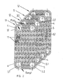
- the identically formed rectangular heat transfer plates 1.1, 1.2 comprise a circumferential raised edge 2, openings 3 provided in the four corner regions and a wave field formed between the openings 3 of approximately trapezoidal shaped waves (wave crests and wave troughs).
- upper heat transfer plate 1.1 are provided on the left longitudinal side first openings 3.1 on a level with respect to the drawing plane plate level 4 in the amount of wave crests, while the second openings 3.2 are located on the left longitudinal side on a lower plate level 5.
- the heat transfer plates 1.1, 1.2 are each stacked rotated by 180 °, so that the formed between two adjacent heat transfer plates 1.1, 1.2 flow channel between the respective upper and lower plate level 4, 5 an inlet opening 6 for a liquid to be evaporated (refrigerant) and an outlet opening 7 has for the steam generated in the flow channel. Evaporation takes place on the hot walls of the flow channel, passing through one in the both sides heated heating medium flowing adjacent flow channels.
- the heat transfer plates 1.1, 1.2 are soldered to each other at the raised edges 2, at the mutual contact points of the waves of adjacent heat transfer plates and at the adjoining the apertures contact surfaces between the upper and lower plate levels.
- An essential feature of the plate heat exchanger used as evaporator is the design of the wave field of the heat transfer plates 1.
- a first wave range 8 from running at an obtuse angle to each other - oblique - waves 8a provided on the two narrow sides of the heat transfer plates 1.1, 1.2.
- This is followed in turn by alternating second straight wave regions 9 with straight waves 9a running in the direction of flow (longitudinal direction of the heat transfer plates) and wave sections and third wave regions 10 with shafts 10a running at an obtuse angle to the flow direction (longitudinal direction of the plates).
- the straight waves 9a and the oblique waves 10a merge into each other.
- the short, straight shaft pieces individually run between the straight shafts 9a.
- the oblique waves 10a extend at the same angle but in the opposite direction and the straight shafts 9a and the straight shaft pieces are offset in the two plate halves by a wave width to each other.
- the cross-sectional area of the straight shafts 9a and the oblique shafts 10a is trapezoidal.
- the flowing in the flow channel between two heat transfer plates from an inlet opening 6 to an outlet opening 7 fluid is well mixed by the wave areas 8, 10 of intersecting waves and distributed to the rotary tube channels receives in each case in the caused by the intersecting waves tangential introduction into the swirl tube channels a swirl pulse. Due to the thus caused in the swirl tube rotating flow (three to ten revolutions) in the fluid after evaporation remaining liquid droplets due to the centrifugal force to the outside, that is to the wall of the swirl tube 11 and the hot surfaces of the heat transfer plates 1.1, 1.2 hurled to accommodate there the heat required for their evaporation can.
Landscapes
- Engineering & Computer Science (AREA)
- Physics & Mathematics (AREA)
- Thermal Sciences (AREA)
- Mechanical Engineering (AREA)
- General Engineering & Computer Science (AREA)
- Heat-Exchange Devices With Radiators And Conduit Assemblies (AREA)
Description
- Die Erfindung betrifft einen Plattenwärmeübertrager zum Verdampfen einer Flüssigkeit, der aus einem Stapel identischer, jedoch jeweils um 180° gedreht aneinander liegender, an ihrem umlaufenden Rand abdichtend miteinander verbundener, rechteckiger Wärmeübertragungsplatten besteht, die im Wechsel Strömungskanäle für ein zu verdampfendes Fluid und für ein Heizfluid einschließen und die mit einem Wellungsmuster aus winklig zur Strömungsrichtung ausgerichteten, sich in den Strömungskanälen kreuzenden Wellen sowie in den Eckbereichen mit Durchbrüchen zur Bildung der Ein- und Austrittsöffnungen der Strömungskanäle versehen sind.
- Ein aus der
DE 3721132 A1 bekannter Plattenwärmetauscher zum Verdampfen einer Flüssigkeit umfasst Wärmeaustauschplatten mit über ihre gesamte Wärmeaustauschfläche gleichbleibendem Wellenmuster. Das ist hinsichtlich der Wärmeaustauschkapazität nicht effizient, da nicht die gesamte zu verdampfende Flüssigkeit auf dem Weg im Strömungskanal die gleiche Wärmebehandlung erfährt. - Ein aus der
DE 69102755 T2 bekannter Plattenwärmetauscher zum Verdampfen einer Flüssigkeiten (Plattenverdampfer) macht sich die bekannte Tatsache zunutze, dass der Wärmeaustausch mit einem in dem Strömungskanal zwischen zwei Wärmeaustauschplatten strömenden Fluid davon beeinflusst wird, wie sich die aneinanderliegenden Wellenberge des Wellenmusters der Wärmeaustauschplatten kreuzen und relativ zur Hauptströmungsrichtung verlaufen. Bei einer Kreuzung des Wellenmusters in stumpfem Winkel bezüglich der Hauptströmungsrichtung ist der Wärmeübergang effizienter als bei spitzem Kreuzungswinkel. DieDE 69192755 T2 schlägt daher Wärmeaustauschplatten mit zur Hauptströmungsrichtung derart in unterschiedlichen Winkeln gewellten Zonen vor, dass der Strömungswiderstand von der einen zur anderen Seite des Strömungskanals allmählich abnimmt und die Wärmeübergangsfläche möglichst wirksam genutzt wird. - Die
DE 19959780 B1 beschreibt Plattenwärmeübertrager, bestehend aus identischen, jeweils um 180° gedreht übereinander gestapelten Wärmeübertragerplatten mit über die gesamte Plattenfläche fischgrätmusterartig schräg verlaufendem Wellenmuster aus Wellenbergen und Wellentälern. Die Wellenberge kreuzen sich in den zwischen den Wärmeaustauschplatten gebildeten Strömungskanälen und stützen sich an den Kreuzungspunkten aufeinander ab. Die Verwendung eines derartigen Plattenwärmetauschers als Verdampfer in der Kältetechnik ist insofern problematisch, als die Strömungskanäle nicht gleichmäßig mit dem Kältemittel beaufschlagt werden und das Kältemittel in den stärker beaufschlagten Strömungskanälen nicht vollständig verdampft wird, Die von dem Kältemitteldampf mitgerissenen, nicht verdampften Kältemitteltröpfchen werden in dem an den Plattenverdampfer anschließenden Sammelrohr selbst von dem in anderen Strömungskanälen überhitzten Dampf nicht nachverdampft. - Der Erfindung liegt die Aufgabe zugrunde, einen Plattenwärmeübertrager der eingangs erwähnten Art so auszubilden, dass dessen effiziente Nutzung auch als Plattenverdampfer gewährleistet ist.
- Erfindungsgemäß wird die Aufgabe mit einem gemäß den Merkmalen des Patentanspruch 1 ausgebildeten Plattenwärmeübertrager gelöst.
- Vorteilhafte Weiterbildungen der Erfindung sind Gegenstand der Unteransprüche.
- Der Grundgedanke der Erfindung besteht bei einem zum Verdampfen einer Flüssigkeit, insbesondere eines Kältemittels eingesetzten Plattenwärmeübertrager der eingangs erwähnten Art darin, dass in den zwischen zwei benachbarten Wärmeübertragungsplatten bestehenden, einen Strömungskanal bildenden Plattenspalt mindestens ein Bereich aus mehreren nebeneinander liegenden, in Längsrichtung (Hauptströmungsrichtung) oder in spitzem Winkel zur Längsrichtung verlaufenden Drallrohrkanälen integriert ist. Die Drallrohrkanäle werden durch an den aneinandergrenzenden Seiten der Wärmeübertragerplatten in derselben Richtung, das heißt in Längsrichtung oder in spitzem Winkel zur Längsrichtung des rechteckigen Plattenwärmeübertragers zueinander parallel verlaufende gerade Wellen gebildet. Das stromauf und stromab des Drallrohrkanalbereichs liegende Wellenfeld aus sich kreuzenden Wellen sorgt zum einen für ein gleichmäßiges Durchmischen und Verteilen des Fluids auf die Drallrohrkanäle und zum anderen für ein druckverlustfreies tangentiales Einleiten und Ausleiten des Fluids in die Drallrohrkanäle bzw. aus den Drallrohrkanälen sowie eine daraus resultierende Rotation des Fluids beim Durchströmen der Drallrohrkanäle. Aufgrund des mit einem Drallimpuls in die Drallrohrkanäle gelangenden Fluids und dessen zirkulierender Bewegung durch die Drallrohrkanäle wird zum einen der Strömungsweg verlängert und ein längerer Kontakt mit der Kanalwand bewirkt und zum anderen werden noch nicht verdampfte, mit dem bereits gebildeten Dampf mitgerissene Flüssigkeitströpfchen aufgrund der Zentrifugalkraft an die heißen Kanalwände geschleudert, so dass der Verdampfungsprozess intensiviert und eine effiziente Nutzung des Plattenwärmeübertragers als Verdampfer gewährleistet ist.
- In Ausgestaltung der Erfindung sind über die Länge des zwischen zwei Wärmeübertragungsplatten vorhandenen Strömungskanals im Wechsel mehrere kurze Wellenbereiche aus sich kreuzenden Wellen und aus Drallrohrkanälen ausgebildet. Am Anfang und Ende bzw. an der Eintritts- und der Austrittsseite des Strömungskanals ist ein Bereich aus sich kreuzenden, als Fischgrätmuster ausgerichteten Wellen vorgesehen.
- In weiterer Ausbildung der Erfindung erstreckt sich der Bereich der nebeneinander liegenden Drallrohrkanäle über die gesamte Breite des Strömungskanals.
- In weiterer Ausgestaltung der Erfindung verlaufen die sich kreuzenden Wellen in einem Winkel von 60 bis 130° in ein- und derselben Winkellage zur Strömungsrichtung, jedoch in den beiden Hälften der jeweiligen Wärmeübertragungsplatte in jeweils entgegen gesetzter Richtung, so dass sich die schrägen Wellen von jeweils um 180° gedreht übereinander gestapelten Wärmeübertragungsplatten kreuzen.
- Gemäß einem weiteren Merkmal der Erfindung gehen die schrägen Wellen und die in Strömungsrichtung oder in spitzem Winkel zur Strömungsrichtung verlaufenden geraden Wellen einer Wärmeübertragungsplatte jeweils ineinander über. Zwischen zwei geraden Wellen der Wärmeübertragungsplatte ist jeweils ein zu diesen parallel verlaufendes separates, gerades Wellenstück ausgeformt. Die in Längsrichtung einander kontaktierenden geraden Wellen und Wellenstücke aneinander grenzender, um 180° zueinander gedrehter Wärmeübertragungsplatten bilden die Drallrohrkanäle.
- In weiterer Ausgestaltung der Erfindung haben die geraden Wellen und Wellenstücke und die schrägen Wellen eine trapezförmige Querschnittsform, so dass die Drallrohrkanäle einen nahezu runden, sechseckigen Querschnitt aufweisen.
- Ein Ausführungsbeispiel der Erfindung wird anhand der Zeichnung, in der
- Fig. 1
- eine Draufsicht einer Wärmeübertragungsplatte; und
- Fig. 2
- mehrere übereinander liegende, jedoch in einer auseinandergezogenen Position dargestellte Wärmeübertragungsplatten eines Plattenverdampfers
- Gemäß dem Ausführungsbeispiel umfassen die identisch ausgebildeten rechteckigen Wärmeübertragungsplatten 1.1, 1.2 einen umlaufenden hochgezogenen Rand 2, in den vier Eckbereichen vorgesehene Durchbrüche 3 und ein zwischen den Durchbrüchen 3 ausgeformtes Wellenfeld aus etwa trapezförmig geformten Wellen (Wellenbergen und Wellentälern). In der in
Fig. 2 oberen Wärmeübertragungsplatte 1.1 befinden sich die an der linken Längsseite vorgesehenen ersten Durchbrüche 3.1 auf einem in Bezug auf die Zeichnungsebene oberen Plattenniveau 4 in Höhe der Wellenberge, während sich die zweiten Durchbrüche 3.2 an der linken Längsseite auf einem unteren Plattenniveau 5 befinden. Die Wärmeübertragungsplatten 1.1, 1.2 sind jeweils um 180° gedreht übereinander gestapelt, so dass der zwischen zwei benachbarten Wärmeübertragungsplatten 1.1, 1.2 gebildete Strömungskanal zwischen dem jeweils oberen und unteren Plattenniveau 4, 5 eine Eintrittsöffnung 6 für eine zu verdampfende Flüssigkeit (Kältemittel) und eine Austrittsöffnung 7 für den im Strömungskanal erzeugten Dampf aufweist. Die Verdampfung erfolgt an den heißen Wänden des Strömungskanals, die durch ein in den beiderseitig benachbarten Strömungskanälen fließendes Heizmedium erwärmt werden. Die Wärmeübertragungsplatten 1.1, 1.2 sind an den hochgezogenen Rändern 2, an den beiderseitigen Berührungsstellen der Wellen aneinandergrenzender Wärmeübertragungsplatten und an den an die Durchbrüche anschließenden Berührungsflächen zwischen oberen und unteren Plattenebenen miteinander verlötet. - Ein wesentliches Merkmal des als Verdampfer eingesetzten Plattenwärmeübertragers (Plattenverdampfer) ist die Gestaltung des Wellenfeldes der Wärmeübertragungsplatten 1. An den beiden Schmalseiten der Wärmeübertragungsplatten 1.1, 1.2 ist ein erster Wellenbereich 8 aus in stumpfem Winkel aufeinander zu laufenden - schrägen - Wellen 8a vorgesehen. Daran schließen sich im Wechsel zweite - gerade - Wellenbereiche 9 mit in Strömungsrichtung (Längsrichtung der Wärmeübertragungsplatten) verläufenden - geraden - Wellen 9a und Wellenstücken und dritte Wellenbereiche 10 mit in stumpfem Winkel schräg zur Strömungsrichtung (Längsrichtung der Platten) verlaufenden Wellen 10a. Die geraden Wellen 9a und die schrägen Wellen 10a gehen ineinander über. Die kurzen, geraden Wellenstücke verlaufen einzeln zwischen den geraden Wellen 9a. In der unteren und der oberen Plattenhälfte verlaufen die schrägen Wellen 10a in gleichem Winkel aber in entgegen gesetzter Richtung und die geraden Wellen 9a sowie die geraden Wellenstücke sind in den beiden Plattenhälften um eine Wellenbreite versetzt zueinander angeordnet. Die Querschnittsfläche der geraden Wellen 9a und der schrägen Wellen 10a ist trapezförmig.
- Beim Übereinanderstapeln der jeweils um 180° gedrehten Wärmeübertragungsplatten kreuzen sich die schrägen Wellen 8a der ersten Wellenbereiche 8 sowie die schrägen Wellen 10a der dritten Wellenbereiche 10 und sind an den Kreuzungspunkten miteinander verlötet. In den aneinandergrenzenden zweiten - geraden - Wellenbereichen 9 benachbarter Wärmeübertragungsplatten 1.1, 1.2 berühren sich die geraden Wellen 9a bzw. Wellenstücke in Längsrichtung, so dass in dem zwischen zwei Wärmeübertragungsplatten vorhandenen Strömungskanal für das zu verdampfende Fluid und dessen bereits verdampften Teil in Längsrichtung des Strömungskanals verlaufende - hier im Querschnitt sechseckige, über die Breite des Strömungskanals nebeneinander liegende - Drallrohrkanäle 11 gebildet werden. In dem zwischen zwei aneinandergrenzenden Wärmeübertragungsplatten bestehenden Strömungskanal sind somit im Wechsel aus sich kreuzenden Wellen (Wellenbereiche 8, 10) und aus nebeneinander liegenden Drallrohrkanälen (Wellenbereiche 9) bestehende Strömungskanalabschnitte vorhanden.
- Das in dem Strömungskanal zwischen zwei Wärmeübertragungsplatten von einer Eintrittsöffnung 6 zu einer Austrittsöffnung 7 strömende Fluid wird durch die Wellenbereiche 8, 10 aus sich kreuzenden Wellen gut durchmischt und auf die Drehrohrkanäle verteilt erhält jeweils bei dem durch die sich kreuzenden Wellen bewirkten tangentialen Einleiten in die Drallrohrkänäle einen Drallimpuls. Aufgrund der dadurch in dem Drallrohrkanal bewirkten rotierenden Strömung (drei bis zehn Umdrehungen) werden in dem Fluid nach der Verdampfung noch verbliebene Flüssigkeitströpfchen infolge der Zentrifugalkraft nach außen, das heißt an die Wand des Drallrohrkanal 11 bzw. an die heißen Flächen der Wärmeübertragungsplatten 1.1, 1.2 geschleudert, um dort die zu ihrer Verdampfung erforderliche Wärme aufnehmen zu können. Durch die Drallrohrkanäle und die rotierende Bewegung des Mediums wird zudem der Strömungsweg des Mediums verlängert, ohne jedoch den Plattenwärmeübertrager selbst zu verlängern und dadurch bauliche Nachteile und höhere Druckverluste in Kauf nehmen zu müssen. Bei der bekanntermaßen ungleichmäßigen Verteilung der zu verdampfenden Flüssigkeit auf die einzelnen Strömungskanale eines Plattenverdampfers gelingt es auch in den ein größeres Flüssigkeitsvolumen aufnehmenden Strömungskanälen die Flüssigkeit vollständig zu verdampfen, das heißt auch die in dem bereits verdampften Anteil mitgerissenen Flüssigkeitströpfchen zu verdampfen.
-
- 1.1
- Wärmeübertragungsplatten
- 1.2
- Wärmeübertragungsplatten
- 2
- hochgezogener Rand
- 3.1
- erste Durchbrüche
- 3.2
- zweite Durchbrüche
- 4
- oberes Plattenniveau
- 5
- unteres Plattenniveau
- 6
- Eintrittsöffnung in Strömungskanal
- 7
- Austrittsöffnung aus Strömungskanal
- 8
- erster fischgrätmusterartiger Wellenbereich
- 8a
- schräge Wellen von 8,
- 9
- zweiter - gerader - Wellenbereich
- 9a
- gerade Wellen von 9
- 10
- dritter - schräger - Wellenbereich
- 10a
- schräge Wellen von 10
- 11
- Drallrohrkanal
Claims (8)
- Plattenwärmeübertrager zum Verdampfen einer Flüssigkeit, der aus einem Stapel identischer, jedoch jeweils um 180° gedreht aneinander liegender, an ihrem umlaufenden Rand abdichtend miteinander verbundener, rechteckiger Wärmeübertragungsplatten besteht, die im Wechsel Strömungskanäle für ein zu verdampfendes Fluid und für ein Heizfluid einschließen und die mit einem Wellungsmuster aus winklig zur Strömungsrichtung ausgerichteten, sich in den Strömungskanälen kreuzenden Wellen sowie in den Eckbereichen mit Durchbrüchen zur Bildung der Ein- und Austrittsöffnungen der Strömungskanäle versehen sind, wobei in den Strömungskanälen mindestens ein zwischen zwei Wellenbereichen (8, 10) aus sich kreuzenden schrägen Wellen (8a, 10a) ausgebildeter Wellenbereich (9) vorgesehen ist,
dadurch gekennzeichnet, dass der Wellenbereich (9) an den aneinandergrenzenden Seiten der Wärmeübertragungsplatten in gleicher Ausrichtung verlaufende gerade Wellen (9a) umfasst, die in Längsrichtung oder in spitzem Winkel zur Längsrichtung des Plattenwärmeübertragers verlaufende Drallrohrkanäle (11) mit tangental ein- und ausgeleiteter rotierender Strömung und verlängertem Strömungsweg des Fluids bilden. - Plattenwärmeübertrager nach Anspruch 1, dadurch gekennzeichnet, dass über die Länge des Strömungskanals im Wechsel mehrere Wellenbereiche (9, 10) aus sich kreuzenden Wellen (10a) und aus jeweils in derselben Richtung verlaufenden, die Drallrohrkanäle bildenden Wellen (9a) vorgesehen sind, wobei am Anfang und Ende des Strömüngskanals ein wellenbereich (8) aus sich kreuzenden Wellen (8a) vorgesehen ist.
- Plattenwärmeübertrager nach Anspruch 1, dadurch gekennzeichnet, dass die Drallrohrkanäle in den jeweiligen Wellenbereichen (8,9,10) in wechselnder Richtung verlaufen.
- Plattenwärmeübertrager nach Anspruch 1, dadurch gekennzeichnet, dass sich der Bereich der Drallrohrkanäle über die Breite des Strömungskanals erstreckt.
- Plattenwärmeübertrager nach Anspruch 2, dadurch gekennzeichnet, dass die sich kreuzenden Wellen (8a) in den Wellenbereichen (8) am Anfang und Ende des Strömungskanals fischgrätmusterartig angeordnet sind.
- Plattenwärmeübertrager nach Anspruch 1, dadurch gekennzeichnet, dass die sich kreuzenden Wellen (10a) in einem Winkel von 60 bis 130° in derselben Winkellage zur Strömungsrichtung verlaufen, jedoch in den beiden Hälften der jeweiligen Wärmeübertragungsplatte in entgegengesetzter Richtung schräg verlaufen, so dass sich die schrägen Wellen (10a) von jeweils um 180° gedreht übereinander gestapelten Wärmeübertragungsplatten kreuzen.
- Plattenwärmeübertrager nach Anspruch 1, dadurch gekennzeichnet, dass die schrägen Wellen (10a) und die in Strömungsrichtung oder in spitzem Winkel zur Strömungsrichtung verlaufenden geraden Wellen (9a) einer Wärmeübertragungsplatte jeweils ineinander übergehen, wobei zwischen zwei geraden Wellen (9a) jeweils ein zu diesen parallel verlaufendes Wellenstück ausgeformt ist und die in Längsrichtung einander kontaktierenden geraden Wellen (9a) und Wellenstücke aneinander grenzender, um 180° zueinander gedrehter Wärmeübertragungsplatten die Drallrohrkanäle (11) bilden.
- Plattenwärmeübertrager nach Anspruch 7, dadurch gekennzeichnet, dass die geraden Wellen (9a) und Wellenstücke und die schrägen Wellen (8a, 10a) eine trapezförmige Querschnittsform haben, so dass die Drallrohrkanäle einen nahezu runden, sechseckigen Querschnitt aufweisen.
Applications Claiming Priority (2)
| Application Number | Priority Date | Filing Date | Title |
|---|---|---|---|
| DE201010036654 DE102010036654A1 (de) | 2010-07-27 | 2010-07-27 | Plattenwärmeübertrager zum Verdampfen einer Flüssigkeit |
| PCT/DE2011/075175 WO2012031589A1 (de) | 2010-07-27 | 2011-07-25 | Plattenwärmeübertrager zum verdampfen einer flüssigkeit |
Publications (2)
| Publication Number | Publication Date |
|---|---|
| EP2598820A1 EP2598820A1 (de) | 2013-06-05 |
| EP2598820B1 true EP2598820B1 (de) | 2015-11-18 |
Family
ID=44658509
Family Applications (1)
| Application Number | Title | Priority Date | Filing Date |
|---|---|---|---|
| EP11758372.4A Active EP2598820B1 (de) | 2010-07-27 | 2011-07-25 | Plattenwärmeübertrager zum verdampfen einer flüssigkeit |
Country Status (3)
| Country | Link |
|---|---|
| EP (1) | EP2598820B1 (de) |
| DE (1) | DE102010036654A1 (de) |
| WO (1) | WO2012031589A1 (de) |
Families Citing this family (4)
| Publication number | Priority date | Publication date | Assignee | Title |
|---|---|---|---|---|
| US12141508B2 (en) | 2020-03-16 | 2024-11-12 | Washington University | Systems and methods for forming micropillar array |
| CN114076543A (zh) * | 2020-08-11 | 2022-02-22 | 山东艾普特暖通技术有限公司 | 六v形波纹高效传热板片及板式类换热器 |
| CN112335816A (zh) * | 2020-12-15 | 2021-02-09 | 石屏县帅虹豆制品有限公司 | 生豆浆热交换快速煮浆法 |
| CN115523141B (zh) * | 2022-09-22 | 2025-02-25 | 中国轻工业长沙工程有限公司 | 涡流管蒸汽再压缩装置 |
Family Cites Families (10)
| Publication number | Priority date | Publication date | Assignee | Title |
|---|---|---|---|---|
| GB1183183A (en) * | 1966-07-08 | 1970-03-04 | Apv Co Ltd | Improvements in or relating to Plate Heat Exchangers |
| GB1288887A (de) * | 1970-01-26 | 1972-09-13 | ||
| DE2616816C3 (de) * | 1976-04-15 | 1983-12-01 | Apparatebau Rothemühle Brandt + Kritzler GmbH, 5963 Wenden | Heizblechpaket für regenerative Wärmetauscher |
| DE3721132C2 (de) | 1987-06-26 | 1995-11-30 | Gea Ahlborn Gmbh & Co Kg | Mehrstufige Plattenverdampferanlage mit in Reihe geschalteten Stufen |
| SE466171B (sv) | 1990-05-08 | 1992-01-07 | Alfa Laval Thermal Ab | Plattfoeraangare daer aatminstone den ena plattan i en foeraangningspassage aer uppdelad i faelt anordnade bredvid varandra mellan plattans laangsidor, vilka faelt uppvisar sinsemellan olika korrugeringsmoenster saa att stroemningsmotstaandet successivt minskar fraan ena sidan till den andra |
| JP3651938B2 (ja) * | 1994-10-24 | 2005-05-25 | 松下エコシステムズ株式会社 | 熱交換素子 |
| JPH10325691A (ja) * | 1997-05-27 | 1998-12-08 | Ishikawajima Harima Heavy Ind Co Ltd | 熱交換器 |
| DE19959780B4 (de) | 1999-04-12 | 2004-11-25 | Rehberg, Peter, Dipl.-Ing. | Plattenwärmeübertrager |
| DE29916493U1 (de) * | 1999-09-14 | 2000-04-06 | FPL Wärmerückgewinnung-Lüftung GmbH, 38889 Blankenburg | Vorrichtung für den Wärmetausch im Kreuzstromprinzip |
| DE202005009948U1 (de) * | 2005-06-23 | 2006-11-16 | Autokühler GmbH & Co. KG | Wärmeaustauschelement und damit hergestellter Wärmeaustauscher |
-
2010
- 2010-07-27 DE DE201010036654 patent/DE102010036654A1/de not_active Ceased
-
2011
- 2011-07-25 EP EP11758372.4A patent/EP2598820B1/de active Active
- 2011-07-25 WO PCT/DE2011/075175 patent/WO2012031589A1/de not_active Ceased
Also Published As
| Publication number | Publication date |
|---|---|
| WO2012031589A1 (de) | 2012-03-15 |
| EP2598820A1 (de) | 2013-06-05 |
| DE102010036654A1 (de) | 2012-03-29 |
Similar Documents
| Publication | Publication Date | Title |
|---|---|---|
| DE3148375C2 (de) | ||
| DE69704576T2 (de) | Wärmeübertragungselement für regenerative vorwärmer | |
| DE69102755T2 (de) | Plattenverdampfer. | |
| DE202005009948U1 (de) | Wärmeaustauschelement und damit hergestellter Wärmeaustauscher | |
| EP1091185A2 (de) | Plattenwärmetauscher | |
| DE4142177C2 (de) | Plattenwärmetauscher | |
| DE1601216B2 (de) | Blechtafel fuer platten waermetauscher mit einem stapel solcher blechtafeln | |
| DE2442420A1 (de) | Desublimator fuer die gewinnung von sublimationsprodukten, insbesondere von phthalsaeureanhydrid, aus reaktionsgasen | |
| EP1256772A2 (de) | Wärmetauscher | |
| DE3347086A1 (de) | Matrix fuer einen katalytischen reaktor zur abgasreinigung | |
| DE19709601A1 (de) | Plattenwärmeübertrager | |
| DE102010036654A1 (de) | Plattenwärmeübertrager zum Verdampfen einer Flüssigkeit | |
| EP1910764B2 (de) | Plattenelement für einen plattenkühler | |
| DE60303276T2 (de) | Wärmetauscherplatte und Plattenwärmetauscher | |
| DE202017104743U1 (de) | Wärmetauscher mit Mikrokanal-Struktur oder Flügelrohr-Struktur | |
| EP2389555B1 (de) | Plattenwärmeübertrager | |
| DE102010036664B4 (de) | Plattenwärmeübertrager | |
| EP1557627A1 (de) | Strömungskanal | |
| AT406301B (de) | Plattenwärmetauscher | |
| DE69820880T2 (de) | Wärmetauscherwirbelerzeuger mit unterbrochenen wellungen | |
| DE102009043828B4 (de) | Plattenwärmeübertrager | |
| EP3535539B1 (de) | Einbaueinrichtung für eine vorrichtung zur behandlung eines nutzfluids mit einem arbeitsfluid | |
| EP1588114A1 (de) | Luft-wasser-wärmetauscher mit teilwasserwegen | |
| EP2899487B1 (de) | Stapelscheibenwärmeübertrager | |
| EP2657635B1 (de) | Plattenwärmetauscher |
Legal Events
| Date | Code | Title | Description |
|---|---|---|---|
| PUAI | Public reference made under article 153(3) epc to a published international application that has entered the european phase |
Free format text: ORIGINAL CODE: 0009012 |
|
| 17P | Request for examination filed |
Effective date: 20130222 |
|
| AK | Designated contracting states |
Kind code of ref document: A1 Designated state(s): AL AT BE BG CH CY CZ DE DK EE ES FI FR GB GR HR HU IE IS IT LI LT LU LV MC MK MT NL NO PL PT RO RS SE SI SK SM TR |
|
| DAX | Request for extension of the european patent (deleted) | ||
| 17Q | First examination report despatched |
Effective date: 20140102 |
|
| GRAP | Despatch of communication of intention to grant a patent |
Free format text: ORIGINAL CODE: EPIDOSNIGR1 |
|
| INTG | Intention to grant announced |
Effective date: 20141128 |
|
| GRAJ | Information related to disapproval of communication of intention to grant by the applicant or resumption of examination proceedings by the epo deleted |
Free format text: ORIGINAL CODE: EPIDOSDIGR1 |
|
| GRAP | Despatch of communication of intention to grant a patent |
Free format text: ORIGINAL CODE: EPIDOSNIGR1 |
|
| INTG | Intention to grant announced |
Effective date: 20150115 |
|
| GRAJ | Information related to disapproval of communication of intention to grant by the applicant or resumption of examination proceedings by the epo deleted |
Free format text: ORIGINAL CODE: EPIDOSDIGR1 |
|
| GRAP | Despatch of communication of intention to grant a patent |
Free format text: ORIGINAL CODE: EPIDOSNIGR1 |
|
| INTG | Intention to grant announced |
Effective date: 20150408 |
|
| GRAC | Information related to communication of intention to grant a patent modified |
Free format text: ORIGINAL CODE: EPIDOSCIGR1 |
|
| INTG | Intention to grant announced |
Effective date: 20150529 |
|
| RIN1 | Information on inventor provided before grant (corrected) |
Inventor name: REHBERG, MICHAEL Inventor name: REHBERG, PETER |
|
| GRAS | Grant fee paid |
Free format text: ORIGINAL CODE: EPIDOSNIGR3 |
|
| GRAA | (expected) grant |
Free format text: ORIGINAL CODE: 0009210 |
|
| AK | Designated contracting states |
Kind code of ref document: B1 Designated state(s): AL AT BE BG CH CY CZ DE DK EE ES FI FR GB GR HR HU IE IS IT LI LT LU LV MC MK MT NL NO PL PT RO RS SE SI SK SM TR |
|
| REG | Reference to a national code |
Ref country code: GB Ref legal event code: FG4D Free format text: NOT ENGLISH |
|
| REG | Reference to a national code |
Ref country code: CH Ref legal event code: EP |
|
| REG | Reference to a national code |
Ref country code: AT Ref legal event code: REF Ref document number: 761776 Country of ref document: AT Kind code of ref document: T Effective date: 20151215 |
|
| REG | Reference to a national code |
Ref country code: IE Ref legal event code: FG4D Free format text: LANGUAGE OF EP DOCUMENT: GERMAN |
|
| REG | Reference to a national code |
Ref country code: DE Ref legal event code: R096 Ref document number: 502011008357 Country of ref document: DE |
|
| REG | Reference to a national code |
Ref country code: NL Ref legal event code: MP Effective date: 20160218 |
|
| REG | Reference to a national code |
Ref country code: LT Ref legal event code: MG4D |
|
| PG25 | Lapsed in a contracting state [announced via postgrant information from national office to epo] |
Ref country code: NO Free format text: LAPSE BECAUSE OF FAILURE TO SUBMIT A TRANSLATION OF THE DESCRIPTION OR TO PAY THE FEE WITHIN THE PRESCRIBED TIME-LIMIT Effective date: 20160218 Ref country code: HR Free format text: LAPSE BECAUSE OF FAILURE TO SUBMIT A TRANSLATION OF THE DESCRIPTION OR TO PAY THE FEE WITHIN THE PRESCRIBED TIME-LIMIT Effective date: 20151118 Ref country code: ES Free format text: LAPSE BECAUSE OF FAILURE TO SUBMIT A TRANSLATION OF THE DESCRIPTION OR TO PAY THE FEE WITHIN THE PRESCRIBED TIME-LIMIT Effective date: 20151118 Ref country code: NL Free format text: LAPSE BECAUSE OF FAILURE TO SUBMIT A TRANSLATION OF THE DESCRIPTION OR TO PAY THE FEE WITHIN THE PRESCRIBED TIME-LIMIT Effective date: 20151118 Ref country code: LT Free format text: LAPSE BECAUSE OF FAILURE TO SUBMIT A TRANSLATION OF THE DESCRIPTION OR TO PAY THE FEE WITHIN THE PRESCRIBED TIME-LIMIT Effective date: 20151118 Ref country code: IS Free format text: LAPSE BECAUSE OF FAILURE TO SUBMIT A TRANSLATION OF THE DESCRIPTION OR TO PAY THE FEE WITHIN THE PRESCRIBED TIME-LIMIT Effective date: 20160318 Ref country code: IT Free format text: LAPSE BECAUSE OF FAILURE TO SUBMIT A TRANSLATION OF THE DESCRIPTION OR TO PAY THE FEE WITHIN THE PRESCRIBED TIME-LIMIT Effective date: 20151118 |
|
| PG25 | Lapsed in a contracting state [announced via postgrant information from national office to epo] |
Ref country code: FI Free format text: LAPSE BECAUSE OF FAILURE TO SUBMIT A TRANSLATION OF THE DESCRIPTION OR TO PAY THE FEE WITHIN THE PRESCRIBED TIME-LIMIT Effective date: 20151118 Ref country code: SE Free format text: LAPSE BECAUSE OF FAILURE TO SUBMIT A TRANSLATION OF THE DESCRIPTION OR TO PAY THE FEE WITHIN THE PRESCRIBED TIME-LIMIT Effective date: 20151118 Ref country code: LV Free format text: LAPSE BECAUSE OF FAILURE TO SUBMIT A TRANSLATION OF THE DESCRIPTION OR TO PAY THE FEE WITHIN THE PRESCRIBED TIME-LIMIT Effective date: 20151118 Ref country code: GR Free format text: LAPSE BECAUSE OF FAILURE TO SUBMIT A TRANSLATION OF THE DESCRIPTION OR TO PAY THE FEE WITHIN THE PRESCRIBED TIME-LIMIT Effective date: 20160219 Ref country code: PL Free format text: LAPSE BECAUSE OF FAILURE TO SUBMIT A TRANSLATION OF THE DESCRIPTION OR TO PAY THE FEE WITHIN THE PRESCRIBED TIME-LIMIT Effective date: 20151118 Ref country code: PT Free format text: LAPSE BECAUSE OF FAILURE TO SUBMIT A TRANSLATION OF THE DESCRIPTION OR TO PAY THE FEE WITHIN THE PRESCRIBED TIME-LIMIT Effective date: 20160318 Ref country code: RS Free format text: LAPSE BECAUSE OF FAILURE TO SUBMIT A TRANSLATION OF THE DESCRIPTION OR TO PAY THE FEE WITHIN THE PRESCRIBED TIME-LIMIT Effective date: 20151118 |
|
| REG | Reference to a national code |
Ref country code: FR Ref legal event code: PLFP Year of fee payment: 6 |
|
| PG25 | Lapsed in a contracting state [announced via postgrant information from national office to epo] |
Ref country code: CZ Free format text: LAPSE BECAUSE OF FAILURE TO SUBMIT A TRANSLATION OF THE DESCRIPTION OR TO PAY THE FEE WITHIN THE PRESCRIBED TIME-LIMIT Effective date: 20151118 |
|
| REG | Reference to a national code |
Ref country code: DE Ref legal event code: R097 Ref document number: 502011008357 Country of ref document: DE |
|
| PG25 | Lapsed in a contracting state [announced via postgrant information from national office to epo] |
Ref country code: SM Free format text: LAPSE BECAUSE OF FAILURE TO SUBMIT A TRANSLATION OF THE DESCRIPTION OR TO PAY THE FEE WITHIN THE PRESCRIBED TIME-LIMIT Effective date: 20151118 Ref country code: SK Free format text: LAPSE BECAUSE OF FAILURE TO SUBMIT A TRANSLATION OF THE DESCRIPTION OR TO PAY THE FEE WITHIN THE PRESCRIBED TIME-LIMIT Effective date: 20151118 Ref country code: RO Free format text: LAPSE BECAUSE OF FAILURE TO SUBMIT A TRANSLATION OF THE DESCRIPTION OR TO PAY THE FEE WITHIN THE PRESCRIBED TIME-LIMIT Effective date: 20151118 Ref country code: DK Free format text: LAPSE BECAUSE OF FAILURE TO SUBMIT A TRANSLATION OF THE DESCRIPTION OR TO PAY THE FEE WITHIN THE PRESCRIBED TIME-LIMIT Effective date: 20151118 Ref country code: EE Free format text: LAPSE BECAUSE OF FAILURE TO SUBMIT A TRANSLATION OF THE DESCRIPTION OR TO PAY THE FEE WITHIN THE PRESCRIBED TIME-LIMIT Effective date: 20151118 |
|
| PLBE | No opposition filed within time limit |
Free format text: ORIGINAL CODE: 0009261 |
|
| STAA | Information on the status of an ep patent application or granted ep patent |
Free format text: STATUS: NO OPPOSITION FILED WITHIN TIME LIMIT |
|
| 26N | No opposition filed |
Effective date: 20160819 |
|
| PG25 | Lapsed in a contracting state [announced via postgrant information from national office to epo] |
Ref country code: SI Free format text: LAPSE BECAUSE OF FAILURE TO SUBMIT A TRANSLATION OF THE DESCRIPTION OR TO PAY THE FEE WITHIN THE PRESCRIBED TIME-LIMIT Effective date: 20151118 |
|
| PG25 | Lapsed in a contracting state [announced via postgrant information from national office to epo] |
Ref country code: BE Free format text: LAPSE BECAUSE OF NON-PAYMENT OF DUE FEES Effective date: 20160731 |
|
| PG25 | Lapsed in a contracting state [announced via postgrant information from national office to epo] |
Ref country code: MC Free format text: LAPSE BECAUSE OF FAILURE TO SUBMIT A TRANSLATION OF THE DESCRIPTION OR TO PAY THE FEE WITHIN THE PRESCRIBED TIME-LIMIT Effective date: 20151118 |
|
| REG | Reference to a national code |
Ref country code: IE Ref legal event code: MM4A |
|
| REG | Reference to a national code |
Ref country code: FR Ref legal event code: PLFP Year of fee payment: 7 |
|
| PG25 | Lapsed in a contracting state [announced via postgrant information from national office to epo] |
Ref country code: IE Free format text: LAPSE BECAUSE OF NON-PAYMENT OF DUE FEES Effective date: 20160725 |
|
| PG25 | Lapsed in a contracting state [announced via postgrant information from national office to epo] |
Ref country code: LU Free format text: LAPSE BECAUSE OF NON-PAYMENT OF DUE FEES Effective date: 20160725 |
|
| REG | Reference to a national code |
Ref country code: AT Ref legal event code: MM01 Ref document number: 761776 Country of ref document: AT Kind code of ref document: T Effective date: 20160725 |
|
| PG25 | Lapsed in a contracting state [announced via postgrant information from national office to epo] |
Ref country code: AT Free format text: LAPSE BECAUSE OF NON-PAYMENT OF DUE FEES Effective date: 20160725 |
|
| PGFP | Annual fee paid to national office [announced via postgrant information from national office to epo] |
Ref country code: CH Payment date: 20170724 Year of fee payment: 7 |
|
| PG25 | Lapsed in a contracting state [announced via postgrant information from national office to epo] |
Ref country code: CY Free format text: LAPSE BECAUSE OF FAILURE TO SUBMIT A TRANSLATION OF THE DESCRIPTION OR TO PAY THE FEE WITHIN THE PRESCRIBED TIME-LIMIT Effective date: 20151118 Ref country code: HU Free format text: LAPSE BECAUSE OF FAILURE TO SUBMIT A TRANSLATION OF THE DESCRIPTION OR TO PAY THE FEE WITHIN THE PRESCRIBED TIME-LIMIT; INVALID AB INITIO Effective date: 20110725 |
|
| PG25 | Lapsed in a contracting state [announced via postgrant information from national office to epo] |
Ref country code: MK Free format text: LAPSE BECAUSE OF FAILURE TO SUBMIT A TRANSLATION OF THE DESCRIPTION OR TO PAY THE FEE WITHIN THE PRESCRIBED TIME-LIMIT Effective date: 20151118 Ref country code: MT Free format text: LAPSE BECAUSE OF FAILURE TO SUBMIT A TRANSLATION OF THE DESCRIPTION OR TO PAY THE FEE WITHIN THE PRESCRIBED TIME-LIMIT Effective date: 20151118 Ref country code: TR Free format text: LAPSE BECAUSE OF FAILURE TO SUBMIT A TRANSLATION OF THE DESCRIPTION OR TO PAY THE FEE WITHIN THE PRESCRIBED TIME-LIMIT Effective date: 20151118 |
|
| REG | Reference to a national code |
Ref country code: FR Ref legal event code: PLFP Year of fee payment: 8 |
|
| PG25 | Lapsed in a contracting state [announced via postgrant information from national office to epo] |
Ref country code: BG Free format text: LAPSE BECAUSE OF FAILURE TO SUBMIT A TRANSLATION OF THE DESCRIPTION OR TO PAY THE FEE WITHIN THE PRESCRIBED TIME-LIMIT Effective date: 20151118 |
|
| PG25 | Lapsed in a contracting state [announced via postgrant information from national office to epo] |
Ref country code: AL Free format text: LAPSE BECAUSE OF FAILURE TO SUBMIT A TRANSLATION OF THE DESCRIPTION OR TO PAY THE FEE WITHIN THE PRESCRIBED TIME-LIMIT Effective date: 20151118 |
|
| REG | Reference to a national code |
Ref country code: CH Ref legal event code: PL |
|
| PG25 | Lapsed in a contracting state [announced via postgrant information from national office to epo] |
Ref country code: LI Free format text: LAPSE BECAUSE OF NON-PAYMENT OF DUE FEES Effective date: 20180731 Ref country code: CH Free format text: LAPSE BECAUSE OF NON-PAYMENT OF DUE FEES Effective date: 20180731 |
|
| PGFP | Annual fee paid to national office [announced via postgrant information from national office to epo] |
Ref country code: GB Payment date: 20190725 Year of fee payment: 9 |
|
| GBPC | Gb: european patent ceased through non-payment of renewal fee |
Effective date: 20200725 |
|
| PG25 | Lapsed in a contracting state [announced via postgrant information from national office to epo] |
Ref country code: GB Free format text: LAPSE BECAUSE OF NON-PAYMENT OF DUE FEES Effective date: 20200725 |
|
| REG | Reference to a national code |
Ref country code: DE Ref legal event code: R081 Ref document number: 502011008357 Country of ref document: DE Owner name: TTZ GMBH & CO. KG, DE Free format text: FORMER OWNER: REHBERG, PETER, DIPL.-ING., 13053 BERLIN, DE |
|
| P01 | Opt-out of the competence of the unified patent court (upc) registered |
Effective date: 20230609 |
|
| PGFP | Annual fee paid to national office [announced via postgrant information from national office to epo] |
Ref country code: DE Payment date: 20250703 Year of fee payment: 15 |
|
| PGFP | Annual fee paid to national office [announced via postgrant information from national office to epo] |
Ref country code: FR Payment date: 20250723 Year of fee payment: 15 |