EP2597928A2 - Diskontinuierliche Kommunikation - Google Patents
Diskontinuierliche Kommunikation Download PDFInfo
- Publication number
- EP2597928A2 EP2597928A2 EP13155887.6A EP13155887A EP2597928A2 EP 2597928 A2 EP2597928 A2 EP 2597928A2 EP 13155887 A EP13155887 A EP 13155887A EP 2597928 A2 EP2597928 A2 EP 2597928A2
- Authority
- EP
- European Patent Office
- Prior art keywords
- base station
- handover
- mobile station
- state
- intermittent
- Prior art date
- Legal status (The legal status is an assumption and is not a legal conclusion. Google has not performed a legal analysis and makes no representation as to the accuracy of the status listed.)
- Granted
Links
- 238000004891 communication Methods 0.000 title claims abstract description 182
- 238000000034 method Methods 0.000 claims abstract description 126
- 230000008859 change Effects 0.000 claims description 14
- 230000008569 process Effects 0.000 description 103
- 230000007704 transition Effects 0.000 description 87
- 230000005540 biological transmission Effects 0.000 description 84
- 230000002093 peripheral effect Effects 0.000 description 22
- 238000005259 measurement Methods 0.000 description 9
- 238000005516 engineering process Methods 0.000 description 7
- 230000002035 prolonged effect Effects 0.000 description 4
- 230000001360 synchronised effect Effects 0.000 description 4
- 230000015556 catabolic process Effects 0.000 description 3
- 239000000470 constituent Substances 0.000 description 3
- 238000006731 degradation reaction Methods 0.000 description 3
- 230000000694 effects Effects 0.000 description 3
- 238000010295 mobile communication Methods 0.000 description 3
- 238000012545 processing Methods 0.000 description 3
- 238000011144 upstream manufacturing Methods 0.000 description 3
- 230000003321 amplification Effects 0.000 description 2
- 238000003199 nucleic acid amplification method Methods 0.000 description 2
- 230000004044 response Effects 0.000 description 2
- 230000001413 cellular effect Effects 0.000 description 1
- 230000003247 decreasing effect Effects 0.000 description 1
- 238000010586 diagram Methods 0.000 description 1
- 230000007774 longterm Effects 0.000 description 1
- 230000002265 prevention Effects 0.000 description 1
- 238000003672 processing method Methods 0.000 description 1
- 230000009467 reduction Effects 0.000 description 1
- 238000012546 transfer Methods 0.000 description 1
Images


Classifications
-
- H—ELECTRICITY
- H04—ELECTRIC COMMUNICATION TECHNIQUE
- H04W—WIRELESS COMMUNICATION NETWORKS
- H04W36/00—Hand-off or reselection arrangements
- H04W36/08—Reselecting an access point
-
- H—ELECTRICITY
- H04—ELECTRIC COMMUNICATION TECHNIQUE
- H04W—WIRELESS COMMUNICATION NETWORKS
- H04W76/00—Connection management
- H04W76/20—Manipulation of established connections
- H04W76/27—Transitions between radio resource control [RRC] states
-
- H—ELECTRICITY
- H04—ELECTRIC COMMUNICATION TECHNIQUE
- H04W—WIRELESS COMMUNICATION NETWORKS
- H04W36/00—Hand-off or reselection arrangements
- H04W36/0005—Control or signalling for completing the hand-off
- H04W36/0011—Control or signalling for completing the hand-off for data sessions of end-to-end connection
- H04W36/0016—Hand-off preparation specially adapted for end-to-end data sessions
-
- H—ELECTRICITY
- H04—ELECTRIC COMMUNICATION TECHNIQUE
- H04W—WIRELESS COMMUNICATION NETWORKS
- H04W36/00—Hand-off or reselection arrangements
- H04W36/24—Reselection being triggered by specific parameters
- H04W36/30—Reselection being triggered by specific parameters by measured or perceived connection quality data
-
- H—ELECTRICITY
- H04—ELECTRIC COMMUNICATION TECHNIQUE
- H04W—WIRELESS COMMUNICATION NETWORKS
- H04W74/00—Wireless channel access
- H04W74/08—Non-scheduled access, e.g. ALOHA
- H04W74/0833—Random access procedures, e.g. with 4-step access
-
- H—ELECTRICITY
- H04—ELECTRIC COMMUNICATION TECHNIQUE
- H04W—WIRELESS COMMUNICATION NETWORKS
- H04W36/00—Hand-off or reselection arrangements
-
- H—ELECTRICITY
- H04—ELECTRIC COMMUNICATION TECHNIQUE
- H04W—WIRELESS COMMUNICATION NETWORKS
- H04W52/00—Power management, e.g. TPC [Transmission Power Control], power saving or power classes
- H04W52/02—Power saving arrangements
- H04W52/0209—Power saving arrangements in terminal devices
-
- H—ELECTRICITY
- H04—ELECTRIC COMMUNICATION TECHNIQUE
- H04W—WIRELESS COMMUNICATION NETWORKS
- H04W76/00—Connection management
- H04W76/20—Manipulation of established connections
- H04W76/28—Discontinuous transmission [DTX]; Discontinuous reception [DRX]
-
- Y—GENERAL TAGGING OF NEW TECHNOLOGICAL DEVELOPMENTS; GENERAL TAGGING OF CROSS-SECTIONAL TECHNOLOGIES SPANNING OVER SEVERAL SECTIONS OF THE IPC; TECHNICAL SUBJECTS COVERED BY FORMER USPC CROSS-REFERENCE ART COLLECTIONS [XRACs] AND DIGESTS
- Y02—TECHNOLOGIES OR APPLICATIONS FOR MITIGATION OR ADAPTATION AGAINST CLIMATE CHANGE
- Y02D—CLIMATE CHANGE MITIGATION TECHNOLOGIES IN INFORMATION AND COMMUNICATION TECHNOLOGIES [ICT], I.E. INFORMATION AND COMMUNICATION TECHNOLOGIES AIMING AT THE REDUCTION OF THEIR OWN ENERGY USE
- Y02D30/00—Reducing energy consumption in communication networks
- Y02D30/70—Reducing energy consumption in communication networks in wireless communication networks
Definitions
- the present invention relates to a handover technique in a mobile communication system where an intermittent communication can be made.
- LTE Long Term Evolution
- 3GPP 3rd Generation Partnership Project
- Fig. 1 is a schematic diagram illustrating the timings of intermittent transmission and reception of a mobile station. An upper portion illustrates the timing of a transmission from a base station to the mobile station, whereas a lower portion illustrates the timing of a transmission from the mobile station to the base station.
- the mobile station periodically verifies whether or not a data transmission to the mobile station itself is made while applying the intermittent reception. Also for an upstream transmission, the mobile station periodically makes an intermittent transmission (DTX: discontinuous transmission) in order to maintain the synchronization of an intermittent communication.
- DTX discontinuous transmission
- the mobile station if it becomes necessary to switch a base station at a connection destination by performing a handover due to a move of the mobile station during the intermittent communication, the mobile station initially needs to change the communication state from the intermittent communication state to an active state before executing the handover process. If the mobile station determines to require a handover, it transmits a state transition request to change the communication state to the active state to the base station at the next intermittent transmission timing.
- Fig. 2 illustrates data transmission/reception timings on the side of the mobile station when a handover is performed during an intermittent communication in the conventional technology.
- the mobile station determines to require a handover on the basis of measurement results by periodically measuring a reception level such as a reception signal intensity, etc., it transmits the state transition request to the base station at the next transmission timing.
- the base station that receives the state transition request changes the communication state of the device, namely, the base station itself from the intermittent communication state to the active state, and transmits a message to instruct the mobile station to change from the intermittent communication state to the active state at the transmission timing of the base station.
- a handover is performed thereafter.
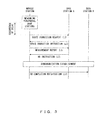
- Fig. 3 is an operational sequence when a handover is performed at the time of an intermittent communication in the conventional technology.
- the state transition request to change to the active state needs to be transmitted at intermittent transmission timing.
- a state transition instruction from the base station that receives the state transition request needs to be transmitted to the mobile station at the intermittent transmission timing. Accordingly, a handover during an intermittent transmission/reception period has a problem of a longer delay time than that of the normal communication (active) state as illustrated in Fig. 3 .
- there is a problem such that the handover is not properly performed because it is not complete within a predetermined duration due to a prolonged time required until the transmission of the state transition request.
- Other handover techniques include a technique (for example, Patent Document 1) for changing to a wireless communication establishment state on the basis of an RRC connection request if it becomes necessary to perform a handover at the time of an intermittent communication, a technique (for example, Patent Document 2) by which a terminal making an intermittent communication forms a paging group and a soft handover is taken into account in a series of sequence, a technique (for example, Patent Document 3) for performing a handover by using a paging channel in an asynchronous system, and a technique (for example, Patent Document 4) for performing a handover under the initiative of a base station.
- Patent Document 1 for changing to a wireless communication establishment state on the basis of an RRC connection request if it becomes necessary to perform a handover at the time of an intermittent communication
- Patent Document 2 by which a terminal making an intermittent communication forms a paging group and a soft handover is taken into account in a series of sequence
- Patent Document 3 for performing a handover by using a paging channel in an
- An object of the present invention is to provide a technique for changing from an intermittent communication state to a normal communication state earlier in a mobile station and a base station, which need to perform a handover, etc.
- an intermittent communication system is an intermittent communication system where an intermittent communication can be made between a base station apparatus and a mobile station apparatus.
- the mobile station apparatus includes a transmitting unit configured to transmit a request to start a normal communication after stopping an intermittent communication at timing different from the intermittent communication if a handover is determined to be required, a transiting unit configured to transit from the intermittent communication to the normal communication after the transmitting unit transmits the request, and a handover performing unit configured to perform a handover upon completion of transiting to the normal communication by the transiting unit.
- the mobile station apparatus in the intermittent communication state immediately transmits to the base station apparatus the request to change the communication to the normal communication state without waiting for the next intermittent transmission timing if it determines a handover to be required. Moreover, the mobile station apparatus transmits the request, and at the same time, it transits from the intermittent communication to the normal communication. Upon completion of transiting to the normal communication, a handover is started. Since the request is transmitted to the base station apparatus regardless of intermittent transmission timing, the amount of time required for the handover process can be reduced.
- the request may be configured with a handover request including base station apparatus identification information for identifying a base station apparatus at a handover destination, and the transiting unit may start to transit from the intermittent communication to the normal communication when the handover request is recognized.
- the communication state is transited on the basis of the handover request received during the intermittent communication, and the handover process is executed upon completion of changing the state, whereby the handover process can be started earlier.
- the request is transmitted from the mobile station apparatus to the base station apparatus by using a common channel. Additionally, the request may be generated as information of L1 (Layer 1: physical layer) and transmitted by the transmitting unit if the period of making an intermittent communication is larger than a predetermined threshold value, or the request may be generated as information of L3 (Layer 3: network layer) and transmitted at the transmission timing of the intermittent communication if the period is equal to or smaller than the predetermined threshold value.
- L1 Layer 1: physical layer
- L3 Layer 3
- the present invention is not limited to the above described intermittent communication system.
- the present invention also covers a base station apparatus and a mobile station apparatus, which apply the above described intermittent communication method, a program for causing a computer to execute a method thereof, and the like.
- a request for the base station apparatus to transit the state regardless of intermittent transmission timing is transmitted by using a common channel even if a handover becomes necessary during an intermittent communication. Since the request is transmitted without waiting for the next intermittent transmission timing, the amount of time required to transit from the intermittent communication state to the normal communication state is reduced. As a result, the amount of time required until the completion of a handover can be shortened. Accordingly, problems such as communication quality degradation, a failure of the handover process, etc., which occur with a prolonged handover process, can be improved.
- a wireless communication system 1 described below is configured by including a mobile station 2 and a base station 3.
- a plurality of base stations 3 exist in the periphery of the mobile station 2.
- the mobile station 2 measures a reception level such as a reception signal intensity, etc. from each of the base stations, and decides a base station 3 at a connection destination from among the plurality of base stations 3 on the basis of the measured reception levels.
- both of the mobile station 2 and the base station 3 make an intermittent transmission/reception (DTX, DRX) even during a communication in order to save power.
- DTX intermittent transmission/reception
- DRX DRX transmission/reception
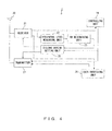
- Fig. 4 illustrates a configuration of the mobile station 2 according to the first embodiment.
- the mobile station 2 includes an antenna 20, a receiver 21, a peripheral level measuring unit 22, a handover determining unit (denoted as an HO determining unit in Fig. 4 ) 23, a controlling unit 24, an intermittent transmission/reception period setting unit (DTX/DRX period setting unit in Fig. 4 : hereinafter referred to as a period setting unit) 25, a data processing unit 26 and a transmitter 27.
- a period setting unit an intermittent transmission/reception period setting unit
- the antenna 20 is used to transmit a signal to the base station 3, or to receive a signal transmitted from the base station 3.
- the transmission antenna and the reception antenna are collectively represented as one antenna.
- the receiver 21 performs amplification and demodulation processes for a signal received via the antenna 20.
- the reception level of the demodulated signal is provided to the peripheral level measuring unit 22.
- the peripheral level measuring unit 22 respectively measures the reception levels of the base stations 3 positioned in the periphery of the mobile station 2.
- the handover determining unit 23 determines whether or not to perform a handover on the basis of results of the measurement made by the peripheral level measuring unit 22. If the handover determining unit 23 determines to perform a handover, it provides the period setting unit 25 with information about performing a handover.
- the period setting unit 25 Upon receipt of the information about performing a handover from the handover determining unit 23, the period setting unit 25 resets the period of intermittent transmission/reception. For example, by setting the value of the period of intermittent transmission/reception to 0, or by setting the period to none, the mobile station 2 executes a communication state transition process from the intermittent communication state to the normal communication state, namely, the active state.
- the active state represents a communication state in contrast to a standby state in the current-generation communication systems. However, in the next-generation systems such as LTE, etc., an intermittent communication can be made even during a communication. Therefore, a communication state in contrast to the intermittent communication state, namely, the state where a non-intermittent communication is made is defined as "the active state".
- the data processing unit 26 processes information obtained by demodulating a signal in the receiver 21, and provides the transmitter 27 with data to be transmitted to the base station 3.
- the data that the data processing unit 26 provides to the transmitter 27 includes the state transition request to request the base station 30 to change the communication state from the intermittent communication state to the active state.
- the transmitter 27 executes a modulation process for the data.
- the signal modulated by the transmitter 27 is transmitted to wireless space via the antenna 20.
- the controlling unit 24 performs various types of controls on the basis of input information. If a handover is determined to be required in the intermittent communication state, the controlling unit 24 performs a control, for example, to instruct the period setting unit 25 to reset the period of intermittent transmission/reception, or to cause the transmitter 27 to execute a modulation process for transmitting the state transition request to the base station 3 as L1 information. In this embodiment, the controlling unit 24 transmits the above described state transition request to the base station 3 regardless of intermittent transmission timing even in the intermittent communication state.
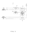
- Fig. 5 illustrates a configuration of the base station 3 according to this embodiment.
- the base station 3 includes an antenna 30, a receiver 31, a state transition request determining unit 32, a state managing unit 33, a scheduler 34 and a transmitter 35.
- the antenna 30 receives a signal from the mobile station 2, and transmits a signal to the mobile station 2.
- the transmission antenna and the reception antenna are collectively depicted as one antenna in Fig. 5 similar to the antenna 20 of the mobile station 2 illustrated in Fig. 4 .
- the receiver 31 executes amplification and demodulation processes for a signal received via the antenna 30. Control information and data of information obtained with the demodulation process are provided to an upper layer, and information received with L1 is provided to the state transition request determining unit 32.
- the information (state transition request) of L1 within the information transmitted from the mobile station 2 is provided to the state transition request determining unit 32, which then determines the contents of the information.
- the state transition request is a request signal for causing the base station 3 to change to a state able to perform a handover by switching the communication state of the base station 3 from the intermittent communication state to the active state, as stated earlier with reference to Fig. 4 .
- the state managing unit 33 manages the communication state on the side of the base station 3 on the basis of results of the determination made by the state transition request determining unit 32. Specifically, the state managing unit 32 manages in which of the intermittent communication state and the active state a communication is made with each mobile station 2 subordinate to the base station 3.
- the scheduler 34 controls data transmission timing according to the management status of the communication state of each mobile station 2 subordinate to the base station 3 in the state managing unit 33.
- Data the transmission timing of which is controlled by the scheduler 34 includes the state transition instruction for instructing the mobile station 2 to change the communication state from the intermittent communication state to the active state.
- the state transition instruction signal is transmitted to the mobile station 2 in accordance with the state transition request received from the mobile station 2.
- the transmitter 35 executes the modulation process for data or various types of control information.
- a signal obtained with the modulation process is transmitted to wireless space via the antenna 30.
- the above described state transition instruction is transmitted regardless of intermittent transmission timing even during an intermittent communication.
- Fig. 6 is an explanatory view of data transmission/reception timings in the mobile station 2 according to this embodiment.
- the upper portion of Fig. 6 illustrates the timing of receiving data from the base station 3, whereas the lower portion of Fig. 6 illustrates the timing of transmitting data to the base station 3.
- the horizontal axis represents time t, whereas the vertical axis represents a duration during which the level is not zero as a duration capable of transmitting/receiving data.
- the mobile station 2 When the mobile station 2 detects that the reception level drops as a result of the measurement during an intermittent communication, it determines to require a handover. Then, the mobile station 2 transmits the state transition request to the base station 3 to request the base station 3 to change from the intermittent communication state to the active state in order to perform a handover.
- the mobile station 2 transmits the state transition request at timing different from the intermittent transmission timing of an intermittent communication. Namely, if the mobile station 2 determines to require a handover, it immediately transmits the state transition request to a base station 3 at a connection destination without waiting for the next intermittent transmission timing.
- the transmission at this time is made by using not an occupied channel assigned to the normal intermittent transmission timing but a common channel such as a random access channel, etc.
- Such a channel is not suitable for transmitting L3 information such as a measurement report like a normal channel, but can transmit information such as the state transition request as L1 information due to its small amount of data. Accordingly, the random access channel is applicable.
- the base station 3 receives the common channel such as the random access channel, etc. regardless of the intermittent transmission/reception timing even when the mobile station 2 is in the intermittent transmission/reception state, and can receive from the mobile station 2 the state transition request that is transmitted at timing other than the intermittent transmission timing.
- the mobile station 2 requests the base station 3 to change the communication state by transmitting the state transition request to the base station 3, and switches the communication state of the mobile station 2 itself from the intermittent communication state to the active state.
- the reception timing is initially changed from the intermittent reception to the active state.
- the mobile station 2 can receive the state transition instruction that is L3 information from the base station 3.
- the base station 3 Upon receipt of the state transition request from the mobile station 2, the base station 3 transmits the state transition instruction to the mobile station 2 after changing the communication state of the base station 3 itself from the intermittent communication state to the active state.
- the mobile station 2 that has transited its state from the intermittent reception state to the active state receives the state transition instruction from the base station 3. Then, the mobile station 2 transits from the intermittent transmission to the active state and starts the handover process upon completion of transition from the intermittent communication state to the active state.
- the state transition instruction from the base station 3 for example, at the timing of transmitting the state transition request signal
- not only the reception state but also the transmission state can be made active (the transmission/reception state can be changed to non-intermittent transmission/reception state).
- the mobile station 2 transmits the state transition request to the base station 3 with L1 without waiting for the next intermittent transmission timing. Accordingly, the state transition process can be executed earlier than the case of transmitting the state transition request at the next intermittent transmission timing, leading to a reduction in the amount of time required to transit the state. The amount of time required to execute the state transition process is reduced, whereby the handover process can be started earlier. As a result, the amount of time required until the completion of the handover process can be decreased.
- a method for transmitting the state transition request at timing different from the intermittent transmission timing is specifically described next.
- Fig. 7 is a sequence of a process for performing a handover during an intermittent communication in a wireless communication system 1 according to this embodiment. Assume that a base station 3 connected before the handover, and a base station 3 at a connection destination after the handover are base stations 3A and 3B, respectively.
- the mobile station 2 determines to require a handover as a result of measuring the reception levels of peripheral base stations 3, it transmits the state transition request to the base station 3A.
- the conventional state transition request is transmitted as L3 information by using an individual channel.
- the state transition request is transmitted as L1 information by using a common channel such as a random access channel, etc. in this embodiment.
- the base station 3A that receives the state transition request changes the communication state of the base station itself to the active state, and notifies the mobile station 2 of scheduling information, etc. by transmitting the state transition instruction to the mobile station 2.
- the mobile station 2 transmits a measurement report to the base station 3A after receiving the state transition instruction.
- the base station 3A transmits a handover instruction to the mobile station 2 after negotiating with the base station 3B at the handover destination.
- the handover process is started.
- a subsequent process, namely, the process with which synchronization is established and the mobile station 2 transmits a handover completion notification to the base station 3B upon completion of the handover is similar to a conventional process and a known technique.
- Fig. 8 illustrates an example format of the state transition request in this embodiment.
- the state transition request is configured by including user identification information (user ID in Fig. 8 ), and a state transition request bit.
- the user identification information is information for identifying the mobile station 2.
- the mobile station 2 is uniquely decided on the basis of the user identification information. If the state transition request bit is set to, for example, 1, it represents the state transition request. If the state transition request bit is set to 0, it represents that the state transition request is not made.
- the notification for requesting the side of the base station to transit the state is exemplified as information transmitted to the base station 3.
- the information transmitted to the base station 3 is not limited to this one.
- the random access channel is equivalent to, for example, a synchronized random access channel in LTE.
- the synchronized random access channel is used when an upstream link between the base station 3 and the mobile station 2 that is a terminal is temporally synchronized by the base station 3.
- the mobile station 2 secures resources for an upstream data transfer by using this channel. With the procedures for a synchronized random access, latency can be reduced as a whole.
- the mobile station 2 transmits the state transition request in the format illustrated in Fig. 8 to the base station 3 as L1 information by using the random access channel, etc. As a result, necessary information can be notified from the mobile station 2 to the base station 3 without waiting for the intermittent transmission timing while reducing the amount of data in comparison with L3 information.
- Fig. 9 is a flowchart illustrating the process executed on the side of the mobile station 2 according to this embodiment. The process illustrated in Fig. 9 is executed according to the measurement period of the reception level from the base station 3, the request from the base station 3, etc.
- step S1 1 is set as the initial value of identification information i for respectively identifying a plurality of base stations 3 positioned in the periphery of the mobile station 2. Then, in step S2, the reception level of an ith base station is measured. In step S3, whether or not the value of i is smaller than the number of base stations (assumed to be N) to be measured is determined. If i is smaller than the number of base stations N to be measured, the process goes to step S4, in which i is incremented by 1. The process then goes back to step S2. If the value of i that is the identification information of the peripheral base station becomes equal to the number of base stations N to be measured, it is determined that the reception levels of all of the base stations 3 have been measured. Then, the process goes to step S5.
- step S5 whether or not to require a handover is determined on the basis of the reception levels measured for the N base stations 3. If the handover is determined not to be required, the process is terminated. If the handover is determined to be required, the process goes to step S6.
- the mobile station 2 immediately transmits the state transition request to the base station 3 regardless of the intermittent transmission timing in step S6, changes the communication state from the intermittent communication state to the active state in step S7, and terminates the process. As stated earlier, after the process illustrated in Fig. 9 is terminated, the mobile station 2 receives the scheduling information included in the state transition instruction from the base station 3, and starts the handover process in accordance with the handover instruction from the base station 3.
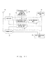
- Fig. 10 is a flowchart illustrating a process executed on the side of the base station 3 according to this embodiment. The process illustrated in Fig. 10 is executed respectively for all of mobile stations 2 that are in the intermittent communication state within the area of the base station 3.
- step S11 whether or not the state transition request is received from the mobile station 2 is determined. If the state transition request is not received, the process goes to step S12, in which the intermittent communication state is continued without executing a process, and the process is terminated. If the state transition request is received from the mobile station 2, the process goes to step S13, in which the communication state of the base station 3 is changed from the intermittent communication state to the active state. Here, the process is terminated.
- the base station 3 After being transited to the active state, the base station 3 notifies the mobile station 2 of scheduling information by transmitting the state transition instruction to the mobile station 2 that transmits the state transition request, and issues the handover instruction to the mobile station 2 in accordance with the measurement report further transmitted from the mobile station 2.
- the mobile station 2 that receives the handover instruction starts the handover.
- the state transition request is transmitted as L1 information by using a common channel, because the amount of data of L1 information is smaller than that of L3 information.
- the common channel is used to transmit the state transition request, whereby the state transition request can be transmitted to the base station 3 at timing different from the intermittent transmission timing when it becomes necessary to perform a handover in the mobile station 2 that is making an intermittent communication.
- the mobile station 2 can immediately transmit the state transition request when determining to require a handover, and the base station 3 can execute the process for transiting the communication state to the active state earlier.
- the handover can be started earlier, and the duration required until the completion of the handover process can be shortened. This contributes to improvements in problems such as communication quality degradation, a failure of the handover process, etc., which occur with a prolonged time required for the handover.
- a wireless communication system 1 according to the second embodiment is characterized in changing from the intermittent communication state to the active state on the basis of information when the information about peripheral base stations is notified as L1 information from the mobile station 2 to the base station 3.
- Fig. 11 illustrates a configuration of the mobile station 2 according to the second embodiment.
- the mobile station 2 according to this embodiment is different from that according to the above described first embodiment in the point of further including a peripheral base station information managing unit 29.
- Other constituent elements are similar to those of Fig. 4 .
- the peripheral base station information managing unit 28 holds information about peripheral base stations, which is received from a base station 3 at a connection destination.
- the information about peripheral base stations is identification information for respectively identifying the peripheral base stations within the mobile station 2.
- Fig. 12 illustrates a configuration of the base station 3 according to this embodiment.
- the base station 3 according to this embodiment is different from that according to the above described first embodiment in the point of further including a peripheral base station information managing unit 36.
- Other constituent elements are similar to those of Fig. 5 .
- the peripheral base station managing unit 36 provides a state managing unit 33 with information about a base station at a handover destination if a handover is determined to be required on the basis of information indicating whether or not to require the handover, which is input from a handover determining unit 32, and provides an upper layer with the information as control information.
- the state managing unit 33 recognizes that the handover is required on the basis of the information about the base station at the handover destination, which is received from the peripheral base station information managing unit 36, and controls the communication state on the side of the base station.
- Fig. 13 is a sequence of a process for performing a handover during an intermittent communication in a wireless communication system 1 according to the second embodiment.
- a base station 3 to which the mobile station 2 is connected before a handover, and a base station 3 at a handover destination are denoted as base stations 3A and 3B, respectively.
- Differences from the sequence of the wireless communication system according to the above described first embodiment illustrated in Fig. 7 are mainly described.
- the base station 3A transmits the state transition instruction to the mobile station 2 in order to change the communication state from the active state to the intermittent communication state.
- the state transition instruction transmitted here includes information for identifying peripheral base stations, which is held in the base station 3A.
- the mobile station 2 that receives the state transition instruction from the base station 3A transits the communication state to the intermittent communication state in accordance with the instruction, and holds the received information in the peripheral base station information managing unit 28.
- the mobile station 2 that is making an intermittent communication transmits a handover request (HO request in Fig. 13 ) to the base station 3A as L1 information by using a random access channel, etc. if it determines to require a handover due to a drop in the reception level. Since the handover request is transmitted as L1 information in this embodiment, it can be transmitted at timing different from intermittent transmission timing.
- the handover request includes the base station identification information for indicating the base station at the handover destination.
- the mobile station 2 initially transits its communication state from the intermittent reception state to the active state after transmitting the handover request, and stands by in the state able to receive L3 information from the base station 3A.
- the base station 3A determines that the handover request has been received on the basis of the L1 information, and transmits a handover instruction to the mobile station 2 after negotiating with the base station 3B at the handover destination.
- the mobile station 2 Upon receipt of the handover instruction from the base station 3A, the mobile station 2 changes its communication state from the intermittent transmission state to the active state.
- the timings of changing from the intermittent reception/transmission to the active state in the mobile station 2 are those after the state transition request is transmitted and after the state transition instruction is received as illustrated in Fig. 6 .
- these timings are those after the handover request is transmitted and after the handover instruction is received in this embodiment.
- synchronization is established similar to the sequence in the above described first embodiment illustrated in Fig. 7 , and the handover is performed.
- a handover completion notification is transmitted to the base station 3B at the handover destination, and the process is terminated.
- the state transition instruction notified to the mobile station 2 in advance is configured by including the base station identification information (denoted as a base station ID in Fig. 13 ).
- the base station identification information may be a value simply assigned by the base station 3A.
- the base station 3A and the mobile station 2 hold the same value.
- the mobile station 2 notifies the base station 3A at the handover source by including the base station identification information in L1 information as described above. Therefore, it is desirable to reduce the amount of data of the information. For example, if the number of peripheral base stations is 10, it is sufficient to secure 4 bits as the amount of data.
- Fig. 14 is an example format of the handover request in this embodiment.
- the handover request is configured by including user identification information (user ID in Fig. 14 ) and the base station identification information (base station ID in Fig. 14 ).
- Information notified to the base station 3 with the handover request is composed of the user identification information for identifying the mobile station 2, and the base station identification information indicating a peripheral base station at a handover destination.
- an intermittent communication is being made even during, for example, a communication other than a standby state in LTE. Therefore, the base station 3 that receives the handover request illustrated in Fig. 14 recognizes that the transition of the communication state is required on the basis of reception of the handover request, and executes the state transition process for the communication state.
- this embodiment eliminates the need for the process of transmitting/receiving information about the base station 3 at the handover destination after changing the communication state on the side of the base station to the active state on the basis of the state transition request. As a result, the amount of time required for the handover process can be further reduced.
- Fig. 15 is a flowchart illustrating a process executed on the side of the mobile station 2 according to the second embodiment. Differences from the process according to the first embodiment illustrated in Fig. 9 are mainly described.
- Steps S21 to S24 respectively correspond to steps S1 to S4 illustrated in Fig. 9 , and similar processes are executed. If it is determined in step S23 that all of peripheral base stations 3 to be measured have been measured, the process goes to step S25.
- step S25 whether or not there is a base station BS i the reception level of which is higher than that of a base station at a handover source BS 0 is determined on the basis of measurement results. If there is no base station the reception level of which is higher than the base station at the handover source, the process is terminated. If there is a base station the reception level of which is higher than the base station at the handover source, the process goes to step S26.
- step S26 After selecting the base station BS i the reception level of which is the highest is selected in step S26, the value i of the base station identification information of the selected base station BS i is stored in the handover request, which is then transmitted to the base station at the handover source. Then, the communication state is transited to the active state in step S28, and the process is terminated. Subsequent processes are similar to those of the above described embodiment.
- Fig. 16 is a flowchart illustrating a process executed on the side of the base station 3 according to the second embodiment. Similar to the base station according to the first embodiment, this process is executed respectively for all of mobile stations 2 that are in the intermittent communication state within the area of the base station 3.
- steps S31 to S32 namely, the processes executed when the handover request is not received from the base station 2 among the processes illustrated in Fig. 16 are similar to those of steps S11 to S12 illustrated in Fig. 10 .
- step S31 If it is determined in step S31 that the handover request is received from the mobile station 2, the process goes to step S33. After changing to the active state in step S33, the handover instruction is transmitted to the mobile station 2 in step S34.
- the base station identification information indicating a base station at a handover destination is included in the handover request, which is transmitted as L1 information.
- the base station 3 can change its communication state to the active state in accordance with the identification information about the base station at the handover destination, which is included in the handover request, and can transmit the handover instruction to the mobile station 2.
- various types of processes for transiting the communication state to the active state after initially recognizing the reception of the state transition request to transit the communication state, and for starting the handover process upon recognition of the reception of the handover request are executed.
- the amount of time required for the handover process can be reduced in the second embodiment.
- the mobile station 2 transmits the handover request to the base station 3 by using a common channel such as a random access channel, etc. if a handover becomes necessary during an intermittent communication.
- the base station 3 at the handover source transits the communication state of the base station 3 itself to the active state in order to cause the mobile station 2, which is the transmission source of the handover request, to perform a handover.
- the handover instruction is transmitted on the basis of the base station identification information indicating the base station at the handover destination, which is included in the handover request.
- the handover request is just transmitted from the mobile station 2 that requires a handover to the base station 3, and information about a base station at a handover destination is included in the handover request and notified, whereby the communication states of both of the mobile station 2 and the base station 3 can be transited.
- the amount of time required for the handover process can be further reduced in comparison with the method for transmitting the request to transit the communication state and the handover request separately from the mobile station 2 to the base station 3. This contributes to improvements in problems such as communication quality degradation, a failure of the handover process, etc., which occur with a prolonged time required for the handover process.
- a wireless communication system 1 according to the third embodiment is characterized in performing a handover by setting a method for transmitting to the base station 3 a request to transit a communication state to the active state in accordance with the period of intermittent transmission/reception.
- Fig. 17 illustrates a configuration of the mobile station 2 according to this embodiment.
- the mobile station 2 according to this embodiment is different from that according to the above described first embodiment in the point that the period setting unit 25 provides the handover determining unit 23 with information about the period of intermittent transmission/reception.
- Other constituent elements are similar to those of Fig. 4 .
- the handover determining unit 23 decides a method for performing a handover, specifically, a method for transmitting the request to transit the communication state to the base station 3 on the basis of the information about the period of intermittent transmission/reception, which is provided from the period setting unit 25. Contents decided by the handover determining unit 23 are provided to the period setting unit 25, which then decides the timing of transmitting the request to the base station 3 on the basis of the input information and provides the transmitter 27 with the timing, and resets the period of intermittent transmission/reception of the mobile station 2 to transit to the active state.
- a configuration of the base station 3 according to this embodiment is similar to that of the base station 3 according to the first embodiment illustrated in Fig. 5 . Therefore, its description is omitted here.
- Fig. 18 is a flowchart illustrating a process executed on the side of the mobile station 2 according to the third embodiment.
- a process executed on the side of the base station 3 is similar to that of the base station 3 according to the first embodiment illustrated in Fig. 10 .
- different processes from the process of the mobile station 2 according to the first embodiment illustrated in Fig. 9 are mainly described.
- Processes from an initialization process in step S41 to the determination of whether or not to require a handover in step S45 respectively correspond to steps S1 to S5 of Fig. 9 , and similar processes are executed. If the handover is determined not to be required in step S45, the process is terminated. If the handover is determined to be required in step S45, the process goes to step S46.
- step S46 whether or not the period of intermittent transmission/reception is equal to or smaller than a predetermined threshold value is determined. If the period of intermittent transmission/reception is larger than the predetermined threshold value, the process goes to step S47, in which the mobile station 2 immediately transmits the state transition request to the base station 3 without waiting for the next intermittent transmission timing. If the period of intermittent transmission/reception is equal to or smaller than the predetermined threshold value in step S46, the process goes to step S48, in which the state transition request is transmitted to the base station 3 at the next intermittent transmission timing. After transmitting the state transition request, the process goes to step S49, in which the communication state of the mobile station 2 is transited to the active state. Here, the process is terminated.
- the period of intermittent transmission/reception is relatively long, a delay in the handover process increases when the transmission of the state transition request is waited until the next intermittent transmission/reception timing. Therefore, it is effective to transmit the state transition request regardless of the intermittent transmission/reception timing by using a common channel such as a random access channel, etc.
- a common channel such as a random access channel, etc.
- using the random access channel can possibly cause a collision between state transition requests if a plurality of mobile stations 2 transmit the state transition requests to one base station 3.
- the effect of reducing a delay in the handover process is recognized to be high and a handover is performed by transmitting the state transition request regardless of the intermittent transmission timing by using a common channel such as a random access channel, etc. if the period of intermittent transmission/reception is larger than a predetermined threshold value, or the effect of reducing a delay in the handover process is recognized not to be so high and a handover is performed with precedence given to the prevention of a collision by transmitting the state transition request at the intermittent transmission timing if the period of intermittent transmission/reception is equal to or smaller than the predetermined threshold value.
- the state transition request is transmitted from the mobile station 2 to the base station 3.
- the handover request in the second embodiment may be transmitted.
- the configuration of the mobile station 2 illustrated in Fig. 11 is implemented as a configuration for providing information about the period of intermittent transmission/reception from the period setting unit 25 to the handover determining unit 23.
- the handover determining unit 23 determines, on the basis of the information about the period of intermittent transmission/reception, whether the handover request is transmitted either as L1 information or as L3 information as in the conventional technology, whereby a similar effect can be produced.
- the base station apparatus executes the signal reception process also at timing other than the predetermined periodical transmission timing of the mobile station apparatus, and allows a second signal to be transmitted to the mobile station apparatus at a period other than a predetermined period in the case of receiving the first signal from the mobile station apparatus with the reception process at timing other than the transmission timing, whereas the mobile station apparatus receives the second signal by executing the signal reception process also at timing other than predetermined periodical reception timing in the case of transmitting the first signal at timing other than the transmission timing.
Landscapes
- Engineering & Computer Science (AREA)
- Computer Networks & Wireless Communication (AREA)
- Signal Processing (AREA)
- Mobile Radio Communication Systems (AREA)
- Transceivers (AREA)
Priority Applications (2)
| Application Number | Priority Date | Filing Date | Title |
|---|---|---|---|
| ES13155887.6T ES2573307T3 (es) | 2007-01-22 | 2007-01-22 | Comunicación discontinua |
| EP13155887.6A EP2597928B1 (de) | 2007-01-22 | 2007-01-22 | Diskontinuierliche Kommunikation |
Applications Claiming Priority (4)
| Application Number | Priority Date | Filing Date | Title |
|---|---|---|---|
| PCT/JP2007/050878 WO2008090592A1 (ja) | 2007-01-22 | 2007-01-22 | 間欠通信システム、基地局装置及び移動局装置 |
| EP07707141.3A EP2129138B1 (de) | 2007-01-22 | 2007-01-22 | System, Mobilstation und Verfahren zur intermittierenden Kommunikation |
| EP12184271.0A EP2542013A3 (de) | 2007-01-22 | 2007-01-22 | Diskontinuierliche Kommunikation |
| EP13155887.6A EP2597928B1 (de) | 2007-01-22 | 2007-01-22 | Diskontinuierliche Kommunikation |
Related Parent Applications (5)
| Application Number | Title | Priority Date | Filing Date |
|---|---|---|---|
| EP07707141.3A Division EP2129138B1 (de) | 2007-01-22 | 2007-01-22 | System, Mobilstation und Verfahren zur intermittierenden Kommunikation |
| EP07707141.3A Division-Into EP2129138B1 (de) | 2007-01-22 | 2007-01-22 | System, Mobilstation und Verfahren zur intermittierenden Kommunikation |
| EP12184271.0A Division EP2542013A3 (de) | 2007-01-22 | 2007-01-22 | Diskontinuierliche Kommunikation |
| EP07707141.3 Division | 2007-01-22 | ||
| EP12184271.0 Division | 2012-09-13 |
Publications (3)
| Publication Number | Publication Date |
|---|---|
| EP2597928A2 true EP2597928A2 (de) | 2013-05-29 |
| EP2597928A3 EP2597928A3 (de) | 2013-09-18 |
| EP2597928B1 EP2597928B1 (de) | 2016-05-18 |
Family
ID=39644174
Family Applications (4)
| Application Number | Title | Priority Date | Filing Date |
|---|---|---|---|
| EP07707141.3A Active EP2129138B1 (de) | 2007-01-22 | 2007-01-22 | System, Mobilstation und Verfahren zur intermittierenden Kommunikation |
| EP12184271.0A Withdrawn EP2542013A3 (de) | 2007-01-22 | 2007-01-22 | Diskontinuierliche Kommunikation |
| EP12184272.8A Withdrawn EP2542014A3 (de) | 2007-01-22 | 2007-01-22 | Datenübertragung und diskontinuierliche Kommunikation |
| EP13155887.6A Active EP2597928B1 (de) | 2007-01-22 | 2007-01-22 | Diskontinuierliche Kommunikation |
Family Applications Before (3)
| Application Number | Title | Priority Date | Filing Date |
|---|---|---|---|
| EP07707141.3A Active EP2129138B1 (de) | 2007-01-22 | 2007-01-22 | System, Mobilstation und Verfahren zur intermittierenden Kommunikation |
| EP12184271.0A Withdrawn EP2542013A3 (de) | 2007-01-22 | 2007-01-22 | Diskontinuierliche Kommunikation |
| EP12184272.8A Withdrawn EP2542014A3 (de) | 2007-01-22 | 2007-01-22 | Datenübertragung und diskontinuierliche Kommunikation |
Country Status (10)
| Country | Link |
|---|---|
| US (2) | US8170029B2 (de) |
| EP (4) | EP2129138B1 (de) |
| JP (1) | JP4690467B2 (de) |
| KR (3) | KR101042502B1 (de) |
| CN (1) | CN101589643B (de) |
| AU (1) | AU2007344826B2 (de) |
| CA (2) | CA2674748A1 (de) |
| ES (2) | ES2573307T3 (de) |
| RU (6) | RU2469503C2 (de) |
| WO (1) | WO2008090592A1 (de) |
Families Citing this family (9)
| Publication number | Priority date | Publication date | Assignee | Title |
|---|---|---|---|---|
| US8023467B2 (en) * | 2007-04-27 | 2011-09-20 | Research In Motion Limited | Method and system for efficient DRX operation during handover in LTE |
| JP5135117B2 (ja) * | 2008-08-08 | 2013-01-30 | 株式会社エヌ・ティ・ティ・ドコモ | 移動局、無線基地局及び移動通信方法 |
| US8520632B2 (en) * | 2008-12-29 | 2013-08-27 | Qualcomm Incorporated | Method and apparatus for synchronization during a handover failure in a wireless communication system |
| JP5313119B2 (ja) * | 2009-12-02 | 2013-10-09 | シャープ株式会社 | 通信装置、通信装置の制御方法、通信装置制御プログラム、及び該プログラムを記録したコンピュータ読み取り可能な記録媒体 |
| JP5782925B2 (ja) * | 2011-08-31 | 2015-09-24 | 富士通株式会社 | 情報処理装置、プログラム、および制御方法 |
| EP3387860B1 (de) * | 2015-12-07 | 2021-02-03 | Telefonaktiebolaget LM Ericsson (publ) | Verfahren und vorrichtungen zur auslösung von mobilitätsreferenzsignalen |
| EP3389331B1 (de) * | 2015-12-31 | 2020-08-26 | Huawei Technologies Co., Ltd. | Verfahren zur mobilitätsverwaltung, vorrichtung und computerlesbares speichermedium |
| EP3389315B1 (de) | 2015-12-31 | 2020-02-05 | Huawei Technologies Co., Ltd. | Mobilitätsverwaltungsverfahren, benutzergerät, speicherknoten und basisstation |
| US11678245B2 (en) * | 2019-12-23 | 2023-06-13 | Qualcomm Incorporated | User equipment (UE) requested enablement for L1/L2 inter-cell mobility |
Citations (4)
| Publication number | Priority date | Publication date | Assignee | Title |
|---|---|---|---|---|
| JP2000069523A (ja) | 1998-08-17 | 2000-03-03 | Fujitsu Ltd | 無線パケット通信システム並びに無線パケット通信システムに使用される移動局及び基地局並びに無線パケット通信システムにおけるパケット転送方法 |
| JP2004504783A (ja) | 2000-07-13 | 2004-02-12 | クゥアルコム・インコーポレイテッド | 非同期通信システムにおいてアイドルモードの再捕捉およびハンドオフを行う方法および装置 |
| JP2004194015A (ja) | 2002-12-12 | 2004-07-08 | Nec Corp | 無線制御装置及びそれを用いた移動通信システム並びにその動作制御方法 |
| JP2005286807A (ja) | 2004-03-30 | 2005-10-13 | Nec Corp | 無線通信端末及びその無線通信早期確立方法 |
Family Cites Families (35)
| Publication number | Priority date | Publication date | Assignee | Title |
|---|---|---|---|---|
| JPH06101698B2 (ja) * | 1986-04-25 | 1994-12-12 | 日本電気株式会社 | 無線電話装置 |
| JPH06216833A (ja) * | 1993-01-14 | 1994-08-05 | N T T Idou Tsuushinmou Kk | 移動通信方式 |
| JP3267059B2 (ja) * | 1994-08-09 | 2002-03-18 | 松下電器産業株式会社 | ディジタル無線電話装置 |
| PT1187358E (pt) * | 1998-03-26 | 2005-01-31 | Mitsubishi Electric Corp | Dispositivo de comunicacoes por alargamento do espectro e metodo de comunicacoes por alargamento do espectro |
| WO2000005910A1 (fr) * | 1998-07-24 | 2000-02-03 | Kabushiki Kaisha Toshiba | Dispositif terminal mobile a acces multiple par code de repartition (amcr) |
| JP3349127B2 (ja) | 1998-07-24 | 2002-11-20 | 株式会社東芝 | Cdma移動端末装置 |
| IL140856A0 (en) * | 1998-07-28 | 2002-02-10 | Samsung Electronics Co Ltd | Gated transmission in control hold state in cdma communication system |
| US6522873B1 (en) * | 1999-12-30 | 2003-02-18 | Samsung Electronics Co., Ltd. | System and method for changing a wireless mobile station between slotted mode operation and non-slotted mode operation |
| KR100338661B1 (ko) * | 2000-08-18 | 2002-07-13 | 윤종용 | 무선 패킷 데이터시스템의 도먼트상태 관리장치 및 방법 |
| KR100375541B1 (ko) * | 2000-11-11 | 2003-03-10 | 엘지전자 주식회사 | 이동통신 시스템의 패킷 도먼트 핸드오프 방법 |
| JP2002199428A (ja) * | 2000-12-27 | 2002-07-12 | Toshiba Corp | 移動通信端末装置とそのハンドオーバ制御方法及び制御プログラム |
| US7136845B2 (en) * | 2001-07-12 | 2006-11-14 | Microsoft Corporation | System and method for query refinement to enable improved searching based on identifying and utilizing popular concepts related to users' queries |
| US7327704B2 (en) * | 2001-10-03 | 2008-02-05 | Motorola, Inc. | Method and apparatus for facilitating dormant mode, packet data mobile handoffs |
| US7558226B2 (en) * | 2001-11-16 | 2009-07-07 | Qualcomm Incorporated | Performing an idle mode handoff in a wireless communication device |
| JP3886795B2 (ja) * | 2001-12-10 | 2007-02-28 | 株式会社エヌ・ティ・ティ・ドコモ | 移動通信システム、移動通信方法、移動端末及び通信基地局 |
| KR100594140B1 (ko) * | 2002-04-13 | 2006-06-28 | 삼성전자주식회사 | 무선통신시스템의 패킷 데이터 서비스 방법 |
| US7133702B2 (en) * | 2002-08-27 | 2006-11-07 | Qualcomm Incorporated | Idle mode cell reacquisition and reselection |
| US7551613B2 (en) * | 2002-09-06 | 2009-06-23 | Motorola, Inc. | Method of supporting reactivation of a dormant session using stored service configurations |
| US7110377B2 (en) * | 2002-10-10 | 2006-09-19 | Qualcomm Incorporated | Dormant handoff in a packet data network |
| KR100483007B1 (ko) * | 2002-12-24 | 2005-04-18 | 한국전자통신연구원 | 차세대 이동통신 시스템에서의 핸드오버 방법 |
| KR20050024125A (ko) * | 2003-09-04 | 2005-03-10 | 삼성전자주식회사 | 광대역 무선 접속 통신 시스템에서 핸드오버를 고려한모드 천이 방법 |
| KR100567211B1 (ko) * | 2003-12-11 | 2006-04-03 | 한국전자통신연구원 | 직교주파수분할 다중접속에서의 임의 접속용 데이터 전송시스템 및 그 방법 |
| US7843881B2 (en) * | 2004-01-08 | 2010-11-30 | Sk Telecom Co., Ltd. | System for packet data service in the mixed network of asynchronous communication network and synchronous communication network and hand-over method thereof |
| CA2557267C (en) * | 2004-03-01 | 2013-04-23 | Kraft Foods Holdings, Inc. | Multi-purpose food preparation kit |
| US7359353B2 (en) * | 2004-04-21 | 2008-04-15 | Motorola, Inc. | Access network and method for improved inter-PDSN dormant mode handoff |
| JP4396379B2 (ja) * | 2004-04-23 | 2010-01-13 | 日本電気株式会社 | 受信ダイバーシティシステムおよびその制御方法 |
| US7558222B2 (en) * | 2004-05-27 | 2009-07-07 | Samsung Electronics Co., Ltd. | System and method for sending IP packets to a mobile station transitioning from dormant state to active state |
| KR100893860B1 (ko) * | 2004-06-10 | 2009-04-20 | 엘지전자 주식회사 | 광대역 무선 접속 시스템에 적용되는 핸드오버 수행 방법및 핸드오버 실패시 통신 재개 방법 |
| JP4735145B2 (ja) * | 2004-10-18 | 2011-07-27 | ソニー株式会社 | 無線通信システム,無線通信装置,およびコンピュータプログラム |
| JP4181107B2 (ja) * | 2004-11-25 | 2008-11-12 | 株式会社カシオ日立モバイルコミュニケーションズ | ハンドオフ制御方法及び移動通信端末 |
| KR100948219B1 (ko) * | 2005-05-16 | 2010-03-18 | 후아웨이 테크놀러지 컴퍼니 리미티드 | 고속 패킷 데이터 네트워크에 있어서 활성 상태에서 인터-액세스 네트워크 핸드오프를 구현하기 위한 방법 및 시스템 |
| US7647078B2 (en) * | 2006-03-07 | 2010-01-12 | Samsung Electronics Co., Ltd. | Power-saving method for wireless sensor network |
| US8064401B2 (en) * | 2006-07-14 | 2011-11-22 | Qualcomm Incorporated | Expedited handoff |
| US7869837B2 (en) * | 2006-12-13 | 2011-01-11 | Nokia Corporation | System and method for implementing mobile IP node lossless transition from an idle state to an awake state |
| US7710987B2 (en) * | 2006-12-14 | 2010-05-04 | Motorola, Inc. | Efficient transitions between operating states in a communication network |
-
2007
- 2007-01-22 EP EP07707141.3A patent/EP2129138B1/de active Active
- 2007-01-22 ES ES13155887.6T patent/ES2573307T3/es active Active
- 2007-01-22 ES ES07707141.3T patent/ES2535834T3/es active Active
- 2007-01-22 WO PCT/JP2007/050878 patent/WO2008090592A1/ja active Application Filing
- 2007-01-22 AU AU2007344826A patent/AU2007344826B2/en active Active
- 2007-01-22 JP JP2008554918A patent/JP4690467B2/ja active Active
- 2007-01-22 CN CN2007800499963A patent/CN101589643B/zh active Active
- 2007-01-22 KR KR1020097015680A patent/KR101042502B1/ko active IP Right Grant
- 2007-01-22 CA CA002674748A patent/CA2674748A1/en not_active Abandoned
- 2007-01-22 EP EP12184271.0A patent/EP2542013A3/de not_active Withdrawn
- 2007-01-22 KR KR1020117006516A patent/KR101098143B1/ko active IP Right Grant
- 2007-01-22 EP EP12184272.8A patent/EP2542014A3/de not_active Withdrawn
- 2007-01-22 KR KR1020117006517A patent/KR101098089B1/ko active IP Right Grant
- 2007-01-22 EP EP13155887.6A patent/EP2597928B1/de active Active
- 2007-01-22 CA CA2938591A patent/CA2938591A1/en not_active Abandoned
-
2009
- 2009-06-29 US US12/493,817 patent/US8170029B2/en active Active
-
2011
- 2011-03-22 RU RU2011110879/07A patent/RU2469503C2/ru active
- 2011-03-22 RU RU2011110832/07A patent/RU2482626C2/ru active
- 2011-03-22 RU RU2011110835/07A patent/RU2482627C2/ru active
-
2012
- 2012-01-30 US US13/361,281 patent/US20120129455A1/en not_active Abandoned
- 2012-10-02 RU RU2012142018/07A patent/RU2012142018A/ru not_active Application Discontinuation
- 2012-10-02 RU RU2012141987/07A patent/RU2521601C2/ru active
- 2012-10-02 RU RU2012142021/07A patent/RU2521603C2/ru active
Patent Citations (4)
| Publication number | Priority date | Publication date | Assignee | Title |
|---|---|---|---|---|
| JP2000069523A (ja) | 1998-08-17 | 2000-03-03 | Fujitsu Ltd | 無線パケット通信システム並びに無線パケット通信システムに使用される移動局及び基地局並びに無線パケット通信システムにおけるパケット転送方法 |
| JP2004504783A (ja) | 2000-07-13 | 2004-02-12 | クゥアルコム・インコーポレイテッド | 非同期通信システムにおいてアイドルモードの再捕捉およびハンドオフを行う方法および装置 |
| JP2004194015A (ja) | 2002-12-12 | 2004-07-08 | Nec Corp | 無線制御装置及びそれを用いた移動通信システム並びにその動作制御方法 |
| JP2005286807A (ja) | 2004-03-30 | 2005-10-13 | Nec Corp | 無線通信端末及びその無線通信早期確立方法 |
Also Published As
Similar Documents
| Publication | Publication Date | Title |
|---|---|---|
| US8170029B2 (en) | Intermittent communication system, base station apparatus and mobile station apparatus | |
| JP5069546B2 (ja) | 通信制御方法、基地局及びユーザ装置 | |
| JP5043108B2 (ja) | 無線インターフェース上でユーザ端末のハンドオーバ処理をする方法、そのための基地局およびネットワーク | |
| JP4916277B2 (ja) | ユーザ装置及びユーザ装置で使用される方法 | |
| RU2416164C2 (ru) | Мобильная станция, сетевое устройство радиодоступа, система мобильной связи и способ приема дискретного приема | |
| CN101785215A (zh) | 在无线通信系统中执行切换的方法 | |
| CN101421946A (zh) | 移动通信系统中切换时执行上行链路定时同步过程的方法和设备 | |
| WO2022077442A1 (en) | Method and apparatus for multicast and broadcast services | |
| US20080026755A1 (en) | Method and system for establishing a multiple transfer mode session | |
| CN114765837A (zh) | 省电处理方法、装置及设备 | |
| RU2420035C2 (ru) | Система прерывистой связи, устройство базовой станции и устройство мобильной станции | |
| JP7431991B2 (ja) | 制御チャネルの監視なしのデータ受信 | |
| WO2023051366A1 (zh) | 一种控制传输的方法及相关装置 | |
| EP4188032A1 (de) | Verfahren und vorrichtung zur verringerung des stromverbrauchs für vorrichtung mit mehreren sim-karten | |
| WO2024068500A1 (en) | Method, apparatus, and system for controlling discontinuous reception in a wireless device |
Legal Events
| Date | Code | Title | Description |
|---|---|---|---|
| PUAI | Public reference made under article 153(3) epc to a published international application that has entered the european phase |
Free format text: ORIGINAL CODE: 0009012 |
|
| AC | Divisional application: reference to earlier application |
Ref document number: 2542013 Country of ref document: EP Kind code of ref document: P Ref document number: 2129138 Country of ref document: EP Kind code of ref document: P |
|
| AK | Designated contracting states |
Kind code of ref document: A2 Designated state(s): AT BE BG CH CY CZ DE DK EE ES FI FR GB GR HU IE IS IT LI LT LU LV MC NL PL PT RO SE SI SK TR |
|
| PUAL | Search report despatched |
Free format text: ORIGINAL CODE: 0009013 |
|
| AK | Designated contracting states |
Kind code of ref document: A3 Designated state(s): AT BE BG CH CY CZ DE DK EE ES FI FR GB GR HU IE IS IT LI LT LU LV MC NL PL PT RO SE SI SK TR |
|
| RIC1 | Information provided on ipc code assigned before grant |
Ipc: H04W 52/02 20090101ALN20130813BHEP Ipc: H04W 76/04 20090101AFI20130813BHEP |
|
| 17P | Request for examination filed |
Effective date: 20140107 |
|
| RBV | Designated contracting states (corrected) |
Designated state(s): AT BE BG CH CY CZ DE DK EE ES FI FR GB GR HU IE IS IT LI LT LU LV MC NL PL PT RO SE SI SK TR |
|
| 17Q | First examination report despatched |
Effective date: 20140404 |
|
| GRAP | Despatch of communication of intention to grant a patent |
Free format text: ORIGINAL CODE: EPIDOSNIGR1 |
|
| RIC1 | Information provided on ipc code assigned before grant |
Ipc: H04W 76/04 20090101AFI20151119BHEP Ipc: H04W 36/00 20090101ALN20151119BHEP Ipc: H04W 52/02 20090101ALN20151119BHEP |
|
| INTG | Intention to grant announced |
Effective date: 20151201 |
|
| INTG | Intention to grant announced |
Effective date: 20151209 |
|
| RIC1 | Information provided on ipc code assigned before grant |
Ipc: H04W 76/04 20090101AFI20151201BHEP Ipc: H04W 52/02 20090101ALN20151201BHEP Ipc: H04W 36/00 20090101ALN20151201BHEP |
|
| GRAS | Grant fee paid |
Free format text: ORIGINAL CODE: EPIDOSNIGR3 |
|
| GRAA | (expected) grant |
Free format text: ORIGINAL CODE: 0009210 |
|
| AC | Divisional application: reference to earlier application |
Ref document number: 2129138 Country of ref document: EP Kind code of ref document: P Ref document number: 2542013 Country of ref document: EP Kind code of ref document: P |
|
| AK | Designated contracting states |
Kind code of ref document: B1 Designated state(s): AT BE BG CH CY CZ DE DK EE ES FI FR GB GR HU IE IS IT LI LT LU LV MC NL PL PT RO SE SI SK TR |
|
| REG | Reference to a national code |
Ref country code: GB Ref legal event code: FG4D |
|
| REG | Reference to a national code |
Ref country code: CH Ref legal event code: EP |
|
| REG | Reference to a national code |
Ref country code: ES Ref legal event code: FG2A Ref document number: 2573307 Country of ref document: ES Kind code of ref document: T3 Effective date: 20160607 |
|
| REG | Reference to a national code |
Ref country code: IE Ref legal event code: FG4D Ref country code: AT Ref legal event code: REF Ref document number: 801395 Country of ref document: AT Kind code of ref document: T Effective date: 20160615 |
|
| REG | Reference to a national code |
Ref country code: DE Ref legal event code: R096 Ref document number: 602007046406 Country of ref document: DE |
|
| REG | Reference to a national code |
Ref country code: NL Ref legal event code: FP |
|
| REG | Reference to a national code |
Ref country code: LT Ref legal event code: MG4D |
|
| PG25 | Lapsed in a contracting state [announced via postgrant information from national office to epo] |
Ref country code: FI Free format text: LAPSE BECAUSE OF FAILURE TO SUBMIT A TRANSLATION OF THE DESCRIPTION OR TO PAY THE FEE WITHIN THE PRESCRIBED TIME-LIMIT Effective date: 20160518 Ref country code: LT Free format text: LAPSE BECAUSE OF FAILURE TO SUBMIT A TRANSLATION OF THE DESCRIPTION OR TO PAY THE FEE WITHIN THE PRESCRIBED TIME-LIMIT Effective date: 20160518 |
|
| REG | Reference to a national code |
Ref country code: AT Ref legal event code: MK05 Ref document number: 801395 Country of ref document: AT Kind code of ref document: T Effective date: 20160518 |
|
| PG25 | Lapsed in a contracting state [announced via postgrant information from national office to epo] |
Ref country code: SE Free format text: LAPSE BECAUSE OF FAILURE TO SUBMIT A TRANSLATION OF THE DESCRIPTION OR TO PAY THE FEE WITHIN THE PRESCRIBED TIME-LIMIT Effective date: 20160518 Ref country code: GR Free format text: LAPSE BECAUSE OF FAILURE TO SUBMIT A TRANSLATION OF THE DESCRIPTION OR TO PAY THE FEE WITHIN THE PRESCRIBED TIME-LIMIT Effective date: 20160819 Ref country code: PT Free format text: LAPSE BECAUSE OF FAILURE TO SUBMIT A TRANSLATION OF THE DESCRIPTION OR TO PAY THE FEE WITHIN THE PRESCRIBED TIME-LIMIT Effective date: 20160919 Ref country code: LV Free format text: LAPSE BECAUSE OF FAILURE TO SUBMIT A TRANSLATION OF THE DESCRIPTION OR TO PAY THE FEE WITHIN THE PRESCRIBED TIME-LIMIT Effective date: 20160518 |
|
| REG | Reference to a national code |
Ref country code: FR Ref legal event code: PLFP Year of fee payment: 11 |
|
| PG25 | Lapsed in a contracting state [announced via postgrant information from national office to epo] |
Ref country code: RO Free format text: LAPSE BECAUSE OF FAILURE TO SUBMIT A TRANSLATION OF THE DESCRIPTION OR TO PAY THE FEE WITHIN THE PRESCRIBED TIME-LIMIT Effective date: 20160518 Ref country code: DK Free format text: LAPSE BECAUSE OF FAILURE TO SUBMIT A TRANSLATION OF THE DESCRIPTION OR TO PAY THE FEE WITHIN THE PRESCRIBED TIME-LIMIT Effective date: 20160518 Ref country code: CZ Free format text: LAPSE BECAUSE OF FAILURE TO SUBMIT A TRANSLATION OF THE DESCRIPTION OR TO PAY THE FEE WITHIN THE PRESCRIBED TIME-LIMIT Effective date: 20160518 Ref country code: SK Free format text: LAPSE BECAUSE OF FAILURE TO SUBMIT A TRANSLATION OF THE DESCRIPTION OR TO PAY THE FEE WITHIN THE PRESCRIBED TIME-LIMIT Effective date: 20160518 Ref country code: EE Free format text: LAPSE BECAUSE OF FAILURE TO SUBMIT A TRANSLATION OF THE DESCRIPTION OR TO PAY THE FEE WITHIN THE PRESCRIBED TIME-LIMIT Effective date: 20160518 |
|
| REG | Reference to a national code |
Ref country code: DE Ref legal event code: R097 Ref document number: 602007046406 Country of ref document: DE |
|
| PG25 | Lapsed in a contracting state [announced via postgrant information from national office to epo] |
Ref country code: BE Free format text: LAPSE BECAUSE OF FAILURE TO SUBMIT A TRANSLATION OF THE DESCRIPTION OR TO PAY THE FEE WITHIN THE PRESCRIBED TIME-LIMIT Effective date: 20160518 Ref country code: AT Free format text: LAPSE BECAUSE OF FAILURE TO SUBMIT A TRANSLATION OF THE DESCRIPTION OR TO PAY THE FEE WITHIN THE PRESCRIBED TIME-LIMIT Effective date: 20160518 Ref country code: PL Free format text: LAPSE BECAUSE OF FAILURE TO SUBMIT A TRANSLATION OF THE DESCRIPTION OR TO PAY THE FEE WITHIN THE PRESCRIBED TIME-LIMIT Effective date: 20160518 |
|
| PLBE | No opposition filed within time limit |
Free format text: ORIGINAL CODE: 0009261 |
|
| STAA | Information on the status of an ep patent application or granted ep patent |
Free format text: STATUS: NO OPPOSITION FILED WITHIN TIME LIMIT |
|
| 26N | No opposition filed |
Effective date: 20170221 |
|
| PG25 | Lapsed in a contracting state [announced via postgrant information from national office to epo] |
Ref country code: SI Free format text: LAPSE BECAUSE OF FAILURE TO SUBMIT A TRANSLATION OF THE DESCRIPTION OR TO PAY THE FEE WITHIN THE PRESCRIBED TIME-LIMIT Effective date: 20160518 |
|
| REG | Reference to a national code |
Ref country code: CH Ref legal event code: PL |
|
| PG25 | Lapsed in a contracting state [announced via postgrant information from national office to epo] |
Ref country code: MC Free format text: LAPSE BECAUSE OF FAILURE TO SUBMIT A TRANSLATION OF THE DESCRIPTION OR TO PAY THE FEE WITHIN THE PRESCRIBED TIME-LIMIT Effective date: 20160518 |
|
| PG25 | Lapsed in a contracting state [announced via postgrant information from national office to epo] |
Ref country code: LI Free format text: LAPSE BECAUSE OF NON-PAYMENT OF DUE FEES Effective date: 20170131 Ref country code: CH Free format text: LAPSE BECAUSE OF NON-PAYMENT OF DUE FEES Effective date: 20170131 |
|
| REG | Reference to a national code |
Ref country code: IE Ref legal event code: MM4A |
|
| REG | Reference to a national code |
Ref country code: DE Ref legal event code: R079 Ref document number: 602007046406 Country of ref document: DE Free format text: PREVIOUS MAIN CLASS: H04W0076040000 Ipc: H04W0076200000 |
|
| PG25 | Lapsed in a contracting state [announced via postgrant information from national office to epo] |
Ref country code: LU Free format text: LAPSE BECAUSE OF NON-PAYMENT OF DUE FEES Effective date: 20170122 |
|
| REG | Reference to a national code |
Ref country code: FR Ref legal event code: PLFP Year of fee payment: 12 |
|
| PG25 | Lapsed in a contracting state [announced via postgrant information from national office to epo] |
Ref country code: IE Free format text: LAPSE BECAUSE OF NON-PAYMENT OF DUE FEES Effective date: 20170122 |
|
| PG25 | Lapsed in a contracting state [announced via postgrant information from national office to epo] |
Ref country code: HU Free format text: LAPSE BECAUSE OF FAILURE TO SUBMIT A TRANSLATION OF THE DESCRIPTION OR TO PAY THE FEE WITHIN THE PRESCRIBED TIME-LIMIT; INVALID AB INITIO Effective date: 20070122 |
|
| PG25 | Lapsed in a contracting state [announced via postgrant information from national office to epo] |
Ref country code: BG Free format text: LAPSE BECAUSE OF FAILURE TO SUBMIT A TRANSLATION OF THE DESCRIPTION OR TO PAY THE FEE WITHIN THE PRESCRIBED TIME-LIMIT Effective date: 20160518 |
|
| PG25 | Lapsed in a contracting state [announced via postgrant information from national office to epo] |
Ref country code: CY Free format text: LAPSE BECAUSE OF NON-PAYMENT OF DUE FEES Effective date: 20160518 |
|
| PG25 | Lapsed in a contracting state [announced via postgrant information from national office to epo] |
Ref country code: TR Free format text: LAPSE BECAUSE OF FAILURE TO SUBMIT A TRANSLATION OF THE DESCRIPTION OR TO PAY THE FEE WITHIN THE PRESCRIBED TIME-LIMIT Effective date: 20160518 |
|
| PG25 | Lapsed in a contracting state [announced via postgrant information from national office to epo] |
Ref country code: IS Free format text: LAPSE BECAUSE OF FAILURE TO SUBMIT A TRANSLATION OF THE DESCRIPTION OR TO PAY THE FEE WITHIN THE PRESCRIBED TIME-LIMIT Effective date: 20160918 |
|
| PGFP | Annual fee paid to national office [announced via postgrant information from national office to epo] |
Ref country code: NL Payment date: 20221220 Year of fee payment: 17 |
|
| PGFP | Annual fee paid to national office [announced via postgrant information from national office to epo] |
Ref country code: ES Payment date: 20230209 Year of fee payment: 17 |
|
| PGFP | Annual fee paid to national office [announced via postgrant information from national office to epo] |
Ref country code: IT Payment date: 20221213 Year of fee payment: 17 |
|
| PGFP | Annual fee paid to national office [announced via postgrant information from national office to epo] |
Ref country code: GB Payment date: 20231219 Year of fee payment: 18 |
|
| PGFP | Annual fee paid to national office [announced via postgrant information from national office to epo] |
Ref country code: FR Payment date: 20231219 Year of fee payment: 18 |
|
| PGFP | Annual fee paid to national office [announced via postgrant information from national office to epo] |
Ref country code: DE Payment date: 20231219 Year of fee payment: 18 |