EP2597359A2 - Module de lumière à projection pour un phare de véhicule automobile - Google Patents
Module de lumière à projection pour un phare de véhicule automobile Download PDFInfo
- Publication number
- EP2597359A2 EP2597359A2 EP12192572.1A EP12192572A EP2597359A2 EP 2597359 A2 EP2597359 A2 EP 2597359A2 EP 12192572 A EP12192572 A EP 12192572A EP 2597359 A2 EP2597359 A2 EP 2597359A2
- Authority
- EP
- European Patent Office
- Prior art keywords
- guide
- light module
- projection light
- elements
- guide elements
- Prior art date
- Legal status (The legal status is an assumption and is not a legal conclusion. Google has not performed a legal analysis and makes no representation as to the accuracy of the status listed.)
- Granted
Links
- 230000003287 optical effect Effects 0.000 claims abstract description 20
- 238000006073 displacement reaction Methods 0.000 claims abstract description 15
- 238000005520 cutting process Methods 0.000 claims description 14
- 238000003780 insertion Methods 0.000 claims description 5
- 230000037431 insertion Effects 0.000 claims description 5
- 230000000295 complement effect Effects 0.000 claims description 4
- 230000007423 decrease Effects 0.000 claims description 4
- 238000009826 distribution Methods 0.000 description 36
- 239000000463 material Substances 0.000 description 10
- 239000007787 solid Substances 0.000 description 6
- 230000008901 benefit Effects 0.000 description 5
- 239000000243 solution Substances 0.000 description 5
- 239000002131 composite material Substances 0.000 description 4
- 230000000694 effects Effects 0.000 description 4
- 230000008859 change Effects 0.000 description 3
- 238000003384 imaging method Methods 0.000 description 3
- 239000002184 metal Substances 0.000 description 3
- 238000000034 method Methods 0.000 description 3
- 230000008569 process Effects 0.000 description 3
- 239000004065 semiconductor Substances 0.000 description 3
- 230000007704 transition Effects 0.000 description 3
- 238000002347 injection Methods 0.000 description 2
- 239000007924 injection Substances 0.000 description 2
- 238000001746 injection moulding Methods 0.000 description 2
- 238000009434 installation Methods 0.000 description 2
- 230000003068 static effect Effects 0.000 description 2
- 230000001133 acceleration Effects 0.000 description 1
- 230000009471 action Effects 0.000 description 1
- 230000004075 alteration Effects 0.000 description 1
- 238000001816 cooling Methods 0.000 description 1
- 230000003247 decreasing effect Effects 0.000 description 1
- 230000001419 dependent effect Effects 0.000 description 1
- 239000006185 dispersion Substances 0.000 description 1
- 230000002349 favourable effect Effects 0.000 description 1
- 230000007774 longterm Effects 0.000 description 1
- 238000004519 manufacturing process Methods 0.000 description 1
- 238000004091 panning Methods 0.000 description 1
- 238000009304 pastoral farming Methods 0.000 description 1
- 235000015277 pork Nutrition 0.000 description 1
- 238000003825 pressing Methods 0.000 description 1
- 230000009467 reduction Effects 0.000 description 1
- 230000004044 response Effects 0.000 description 1
- 238000010079 rubber tapping Methods 0.000 description 1
- 238000003860 storage Methods 0.000 description 1
- 239000012780 transparent material Substances 0.000 description 1
Images


Classifications
-
- G—PHYSICS
- G02—OPTICS
- G02B—OPTICAL ELEMENTS, SYSTEMS OR APPARATUS
- G02B7/00—Mountings, adjusting means, or light-tight connections, for optical elements
- G02B7/02—Mountings, adjusting means, or light-tight connections, for optical elements for lenses
- G02B7/023—Mountings, adjusting means, or light-tight connections, for optical elements for lenses permitting adjustment
-
- F—MECHANICAL ENGINEERING; LIGHTING; HEATING; WEAPONS; BLASTING
- F21—LIGHTING
- F21S—NON-PORTABLE LIGHTING DEVICES; SYSTEMS THEREOF; VEHICLE LIGHTING DEVICES SPECIALLY ADAPTED FOR VEHICLE EXTERIORS
- F21S41/00—Illuminating devices specially adapted for vehicle exteriors, e.g. headlamps
- F21S41/10—Illuminating devices specially adapted for vehicle exteriors, e.g. headlamps characterised by the light source
- F21S41/14—Illuminating devices specially adapted for vehicle exteriors, e.g. headlamps characterised by the light source characterised by the type of light source
- F21S41/141—Light emitting diodes [LED]
- F21S41/147—Light emitting diodes [LED] the main emission direction of the LED being angled to the optical axis of the illuminating device
- F21S41/148—Light emitting diodes [LED] the main emission direction of the LED being angled to the optical axis of the illuminating device the main emission direction of the LED being perpendicular to the optical axis
-
- F—MECHANICAL ENGINEERING; LIGHTING; HEATING; WEAPONS; BLASTING
- F21—LIGHTING
- F21S—NON-PORTABLE LIGHTING DEVICES; SYSTEMS THEREOF; VEHICLE LIGHTING DEVICES SPECIALLY ADAPTED FOR VEHICLE EXTERIORS
- F21S41/00—Illuminating devices specially adapted for vehicle exteriors, e.g. headlamps
- F21S41/20—Illuminating devices specially adapted for vehicle exteriors, e.g. headlamps characterised by refractors, transparent cover plates, light guides or filters
- F21S41/25—Projection lenses
- F21S41/255—Lenses with a front view of circular or truncated circular outline
-
- F—MECHANICAL ENGINEERING; LIGHTING; HEATING; WEAPONS; BLASTING
- F21—LIGHTING
- F21S—NON-PORTABLE LIGHTING DEVICES; SYSTEMS THEREOF; VEHICLE LIGHTING DEVICES SPECIALLY ADAPTED FOR VEHICLE EXTERIORS
- F21S41/00—Illuminating devices specially adapted for vehicle exteriors, e.g. headlamps
- F21S41/20—Illuminating devices specially adapted for vehicle exteriors, e.g. headlamps characterised by refractors, transparent cover plates, light guides or filters
- F21S41/29—Attachment thereof
- F21S41/295—Attachment thereof specially adapted to projection lenses
-
- F—MECHANICAL ENGINEERING; LIGHTING; HEATING; WEAPONS; BLASTING
- F21—LIGHTING
- F21S—NON-PORTABLE LIGHTING DEVICES; SYSTEMS THEREOF; VEHICLE LIGHTING DEVICES SPECIALLY ADAPTED FOR VEHICLE EXTERIORS
- F21S41/00—Illuminating devices specially adapted for vehicle exteriors, e.g. headlamps
- F21S41/60—Illuminating devices specially adapted for vehicle exteriors, e.g. headlamps characterised by a variable light distribution
- F21S41/68—Illuminating devices specially adapted for vehicle exteriors, e.g. headlamps characterised by a variable light distribution by acting on screens
- F21S41/683—Illuminating devices specially adapted for vehicle exteriors, e.g. headlamps characterised by a variable light distribution by acting on screens by moving screens
- F21S41/698—Shaft-shaped screens rotating along its longitudinal axis
-
- G—PHYSICS
- G02—OPTICS
- G02B—OPTICAL ELEMENTS, SYSTEMS OR APPARATUS
- G02B19/00—Condensers, e.g. light collectors or similar non-imaging optics
- G02B19/0004—Condensers, e.g. light collectors or similar non-imaging optics characterised by the optical means employed
- G02B19/0028—Condensers, e.g. light collectors or similar non-imaging optics characterised by the optical means employed refractive and reflective surfaces, e.g. non-imaging catadioptric systems
-
- G—PHYSICS
- G02—OPTICS
- G02B—OPTICAL ELEMENTS, SYSTEMS OR APPARATUS
- G02B19/00—Condensers, e.g. light collectors or similar non-imaging optics
- G02B19/0033—Condensers, e.g. light collectors or similar non-imaging optics characterised by the use
- G02B19/0047—Condensers, e.g. light collectors or similar non-imaging optics characterised by the use for use with a light source
- G02B19/0061—Condensers, e.g. light collectors or similar non-imaging optics characterised by the use for use with a light source the light source comprising a LED
Definitions
- the present invention relates to a projection light module for a motor vehicle headlight according to the preamble of claim 1.
- a projection light module has a complex light source with a carrier element and a lens holder, with which a secondary optics of the projection light module is attached to the carrier element
- Such a projection light module is for example from DE 10 2009 032 456 A1 known.
- a complex light source here means the structural unit comprising a light source, a primary optic, a diaphragm and the support element which holds these elements together relative to one another.
- the primary optics focuses light from the light source into a first light distribution that is located inside the light source Projection light module is located.
- the first light distribution is limited by an edge of an aperture projecting into the first light distribution.
- the projection light module on a secondary optics, which is focused on the first light distribution and which images the first light distribution as a second light distribution in the apron in front of the vehicle headlight.
- the carrier element serves as the structural basis of the complex light source and the entire projection light module.
- a carrier element can either be a separate component or it can be realized for example by a correspondingly stable, serving as a primary reflector. This is in the aforementioned DE 10 2009 032 456 A1 the case.
- a projection lens serving as secondary optics is generally connected to the carrier element via a lens holder.
- the lens holder also serves to produce a predetermined distance of the secondary optics from the diaphragm edge. This distance usually corresponds to the focal length of the projection lens.
- the aperture edge is projected as a cut-off in height and reversed in the apron in front of the projection light module.
- the light-dark border thus separates a bright area from a dark area of the light distribution of the projection light module.
- the distance of the lens from the diaphragm edge and the angular position of the lens relative to the optical axis influence the quality of the imaging of the diaphragm edge as a light-dark boundary of the light distribution.
- a fringe of color may result in the second light distribution at the cut-off line.
- a color fringe is understood to mean the effect that a narrow, rather reddish, or rather bluish transition region is visible at the light-dark boundary.
- a projection lens having a focal length. Strictly speaking, one has to speak of a medium focal length, since the focal length is wavelength-dependent and in particular smaller for blue light than for red Light is. Blue light is therefore more strongly refracted than red light.
- An optical system for example the primary optics of the projection light module, focuses white light into the first light distribution, which is located at a distance of the average focal length of the secondary optics before the secondary optics. Divergent white light then emanates from the first light distribution and falls onto a light entry surface of the lens. A diaphragm is pushed into the beam path transversely to an optical axis of the lens so far that the optical axis touches the diaphragm edge in a grazing manner.
- a reddish-colored transition region results, that is, a color fringe dominated by a red color impression. If, on the other hand, the aperture lies in the light propagation direction before the first light distribution, ie outside the medium focal length, a bluish transition region results, that is to say a bluish fringe of color.
- the coloration and the intensity of the disturbing color fringes thus depend in particular on the position of the aperture in relation to the focal length of the projection lens. In the case of an incorrect position, unwanted color-intensive color fringes in particular can occur at the cut-off line.
- the lens holder is made of sheet metal and has a receiving ring for receiving the Lens and at least three projecting from the receiving ring struts, which serve to produce the required for the imaging of the diaphragm edge distance between the diaphragm edge and the lens.
- Each strut has a tab which serves for fastening the strut to the support element of the complex light source, there in particular to the reflector.
- the receiving ring is adapted to be connected to a lens holding ring which holds the lens in the axial direction in the receiving ring.
- the lens is inserted into the receiving ring.
- the exact position of the lens in the pickup ring is adjusted for the purpose of color fringe correction, and the lens is fixed in the set position.
- the lens holding ring is slid over the edge of the lens. In the end position of the lens holding ring this is pressed radially inward in the region of the underlying recesses in the receiving ring and thus positively and positively connected to the receiving ring. As a result, the lens is held at a fixed distance from the diaphragm between the receiving ring and the lens holder ring pressed therewith.
- the projection light modules have to meet more and more demands on their appearance beyond their lighting function.
- the aim is to be able to use lens holder made of plastic, as resulting from the use of plastic design degrees of freedom, at least at the same Costs with metallic lens holders can not be realized.
- the object of the invention in the specification of a projection light module of the type mentioned, which allows the use of plastic as a material for the lens holder.
- the projection light module must allow a color fringe correction by adjusting the distance between the lens and the diaphragm edge and, for design reasons, it should also permit the use of lenses which do not have a circular circumference.
- the present invention differs from the aforementioned prior art in that the lens holder has first guide elements and the carrier element second guide elements, and in that the projection light module has locking elements which are arranged and arranged both in the first guide elements and in to engage the second guide elements and a mutual displacement block the guide elements, wherein the first guide elements and the second guide elements interlock and adapted to each other are adapted to allow a release against each other with released locking elements, which is parallel to an optical axis of the projection light module.
- the distance between the lens and the support element and thus ultimately between the lens and the diaphragm edge can be adjusted to a color fringe correction to enable.
- the displacement can then be blocked so that a color correction carried out once is maintained.
- a preferred embodiment is characterized in that the locking elements are screws.
- the locking elements are pins which have at least one cutting edge which extends parallel to the longitudinal axis of such a pin and protrudes laterally from the core diameter of such a pin.
- the locking elements are guided in holes in the second guide elements, which are aligned transversely to the optical axis and arranged so that the first guide elements and the second guide elements are braced against each other during insertion or insertion of the locking elements.
- the bore is arranged relative to a recess in the second guide member so that thread flanks or cutting edges of a guided by the bore locking element protrude into the recess in the second guide element, so that thread flanks or cutting edges of the locking element when screwing or pushing into the hole , which is located in the second guide element, cut into a first guide element, which is located in the recess of the second guide element.
- the diameter of the bore corresponds to a core diameter or an outer diameter of the locking element.
- the bore is located relative to the recess so that a boundary surface of the recess touches or breaks through the cylinder jacket surface of the bore.
- the cross section of the recess in the second guide element and the complementary cross section of the first guide element in the plane perpendicular to the displacement direction has a shape in which the respective diameter of the cross section in the direction of the longitudinal axis of the screw with increasing radial distance the screw is reduced.
- a further preferred embodiment is characterized in that the second guide elements are arranged on the support element and aligned so that the diameter of a cross section having a second guide element, in one direction reduced, which is opposite to the direction in which the diameter of the cross section of an adjacent second guide member decreases.
- At least the first guide elements are made of plastic.
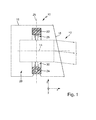
- FIG. 1 In contrast to a luminaire, a motor vehicle headlamp is a lighting device which is set up to illuminate the travel path of a motor vehicle in such a way that a driver of the motor vehicle can recognize obstacles lying in the roadway in good time.
- the headlamp emits a directed light beam 12, which generates a predetermined, legally required light distribution in the run-up to the pork launcher 10
- FIG. 1 shows in particular a highly schematic cross section of a headlamp 10, wherein the cutting plane is parallel to an optical axis 14 of the headlamp 10.
- a coordinate system is shown with which the different directions of view used in the figures can be related to each other. It is a firmly connected to the headlight 10 Coordinate system.
- the x-direction is parallel to the longitudinal axis of the vehicle and points forwards, while the y-direction is parallel to a transverse axis and the z-direction is parallel to a vertical axis of the vehicle.
- the headlight 10 has a housing 16 with a light exit opening.
- the light exit opening is covered by a transparent cover 18.
- a projection light module 20 is arranged inside the housing 16.
- the projection light module 20 has an outer frame 22, which is mounted pivotably about a first axis 24 in the housing 16.
- the first axis 24 is transverse to the optical axis 14, which otherwise corresponds to a Hauptlichtabstrahlraum.
- the first axis 24 is at a proper use transverse to a vertical axis of the motor vehicle and thus in a vehicle on a flat surface, generally parallel to the horizon.
- the pivoting about the first axis 24 allows a headlight range control, which is effected by detecting an inclination of the motor vehicle and the pivoting position of the projection light module 20 about the first axis 24 is automatically adjusted in response to the detected inclination that the emission direction of the light beam 12 is constant regardless of the inclination of the motor vehicle.
- a controlled change in the range as it increases in an upward panning. This is used in one embodiment for raising the light beam for a motorway light distribution.
- an assembly of the projection light module is pivotally suspended about a second axis 26.
- the second axis 26 is in a proper use in a motor vehicle substantially parallel to a vertical axis of the motor vehicle.
- the first axis 24 and the second axis 26 are preferably aligned at right angles to each other.
- the pivoting about the second axis 26 allows during operation of the motor vehicle, a pivoting of the light beam 12 to the right and left to better illuminate the road when cornering.
- the light beam 12 is pivoted to the inside of the curve, e.g. depending on a steering angle detected for this purpose.
- Fig. 1 shows each of the two bearings schematically as a pairing of a bearing pin and a bearing sleeve, wherein the bearing pin is in each case a part of the outer frame 22 mounted assembly.
- This arrangement may also be the other way round in one of the bearings or even in both bearings. You can also use different bearings.
- the basic mode of operation of the cornering light function and the drive used for a cornering light function are familiar to the person skilled in the art and need no further explanation here.
- Fig. 2 shows an embodiment of a tiltable projection light module 20 having features of the invention.
- a projection light module 20 according to the invention need not all of the in the Fig. 2 or even the in the Fig. 1 have shown features. In particular, it does not have to be pivotable about a first axis 24 for a headlight range control or about a second axis 26 for a cornering light function. However, it is essential that it is a projection light module, regardless of whether a cornering light function and / or a headlight range control is realized.
- a projection light module 20 has a secondary optics 32 which is adapted to an internal light distribution, which is in the interior of the projection light module 20 at a distance of a focal length of the secondary optics 32 in the light path in front of the secondary optics 32 from the light 12 of a light source 40 of the Projection light module 20 forms or is formed to project as an external light distribution in the apron of the headlamp 10.
- the secondary optics 32 is usually a projection lens 34.
- a lens is understood here to mean a transparent solid whose light-directing optical effect is limited to the refraction of light upon entry into the solid and upon exit from the solid.
- a lens can also serve a transparent solid, in which the light directing effect results, at least in part, by internal total reflection of the light at interfaces of the solid.
- secondary optics instead of the term “secondary optics", the more illustrative notion of a lens or projection lens 34 is generally used, but it should always be understood that the lens 34 could also be replaced by said alternative solid having the property of an internal lens Total reflection uses.
- the internal light distribution may be a light distribution as provided directly by a light source. It may be, for example, the light exit surface of a semiconductor light source, which in turn is composed of the light exit surfaces of one or more light-emitting diodes or laser diodes. For headlamps of motor vehicles white light-emitting LEDs are used, each having a single square or rectangular light exit surface with edge lengths between about 0.5 mm and 2 mm.
- the inner light distribution is generated from light that is focused by a primary optics on a point or a small area within the projection light module, which is at a distance of a focal length of the projection lens 34 in the light path in front of the projection lens 34.
- Such a focusing takes place in the subject matter of Fig. 2 by a primary optics 36 in the form of a reflector 38, which is adapted to focus from a first focus of the reflector 38 outgoing light into a second focus of the reflector 38.
- a primary optics 36 in the form of a reflector 38, which is adapted to focus from a first focus of the reflector 38 outgoing light into a second focus of the reflector 38.
- this is the case with an ellipsoid reflector in which the light source 40 is seated in the one focal point.
- the projection lens will then focused on the other, second focus of the reflector 38 arranged.
- Deviating from the purely elliptical shape but other forms are common, in which the reflector 38 is shaped so that it generates an internal light distribution with a desired shape. In one embodiment, this is achieved by so-called free-form reflectors, the shape of which is calculated and produced in accordance with the calculations so that predetermined surface elements of the reflector 38 reflect incident light just in such a way that the desired light distribution results.
- a light-refracting optic such as a lens or a light-refractive optic made of transparent material that directs internal total reflections to generate the internal light distribution.
- An optic which generates the inner light distribution is also referred to here as the primary optic 36.
- An aperture 42 is disposed in the focal area of the primary optics 36 and the secondary optics 32 and serves to create a desired shape of the internal light distribution by shading. For example, a bright-dark boundary of the inner light distribution created by the stop 42 is projected into the outer light distribution to achieve, for example, a low-beam distribution.
- the diaphragm 42 is in a preferred embodiment, a diaphragm roller with a surface which deviates from a pure cylindrical shape and depending on the angular position of the diaphragm roller differently shaped diaphragm edges and aperture radii R, r provides. By changing the Angular position can thus vary the shape and position of a light-dark boundary and / or produce a light distribution without pronounced cut-off.
- the quality of the external light distribution depends in particular on the distance 58 of the secondary optics 32 from the internal light distribution, as has already been explained in the introduction.
- the distance 58 corresponds approximately to a mean focal length of the secondary optics.
- the FIG. 2 shows in particular a projection light module 20 for a motor vehicle headlight 10 with a complex light source 44.
- the complex light source 44 has a support member 46 to which a lens holder 48 can be attached.
- the carrier element 46 is preferably a composite part of a first carrier structure 50 made of metal and a second carrier structure 52 made of plastic.
- the composite part is produced, for example, by placing a part of the first carrier structure 50 in an injection mold, with which the second carrier structure 52 is produced.
- the second carrier structure 52 is produced, the inserted part of the first carrier structure 50 is then embedded in the material of the second carrier structure 52 so that the composite part results when the material of the second carrier structure 52 hardens.
- the metallic first support structure 50 has a high heat capacity and thermal conductivity, which is favorable for effective cooling of a semiconductor light source used as a light source 40.
- the semiconductor light source is preferably mounted in good thermal contact on the first support structure 50.
- the preferred second plastic support structure 52 has the advantage that complex shapes, the attachment of the aperture 42, required for an adjustable aperture 42 aperture drive, the connection of the drive an optional curve light function, the associated storage and in particular the attachment structures for the secondary optics 32 by a plastic injection molded part as a lens holder 48 can be realized comparatively simple and inexpensive.
- the lens holder 48 has first guide elements 54, and the carrier element 46 has second guide elements 56.
- the first guide elements 54 and the second guide elements 56 engage with each other.
- the first guide elements 54 and the second guide elements 56 are adapted to each other to allow a mutual displacement, which is parallel to the optical axis 14 of the projection light module 20. In the other two Spatial directions, on the other hand, do not allow any relative movement between the lens holder 48 and the carrier element 46.
- the displaceability allows adjustment of the distance 58 between the projection lens 34 and the internal light distribution.
- the displaceability in particular allows the setting of a distance 58, are minimized in the disturbing color effects that occur at the light-dark boundary in the second light distribution.
- the projection light module 20 has locking elements 60 (cf. Fig. 3 ) on.
- the locking elements are preferably screws 62 (cf. Fig. 3 ).
- the screws 62 are preferably guided in holes 64 in the second guide elements 56, which are aligned transversely to the optical axis 14 and arranged so that the first guide elements 54 and the second guide elements 56 are braced against each other during insertion of the locking elements.
- the first guide elements 54 and the second guide elements 56 are therefore not braced against each other and are therefore parallel to the optical axis 14 against each other.
- the color fringe correction is performed.
- the distance 58 between the projection lens 34 and the inner light distribution is changed by moving the first guide elements 54 against the second guide elements 56 until the disturbing color fringes are minimal. Subsequently, this distance 58 is fixed by fixing the locking elements 60.
- At least the first guide elements 54 but preferably the first guide elements 54 and the second guide elements 56 made of plastic.
- the first guide elements 54 are preferably a cohesive part of the lens holder 48 and are generated together with this in an injection molding process.
- the locking members 60 are configured and arranged to engage both the first guide members 54 and the second guide members 56 and to block mutual displacement of the guide members 54 and 56.
- first guide elements 54 and the second guide elements 56 engage with each other, wherein they are adapted to each other to allow a release against each other with released locking elements 60, which takes place parallel to an optical axis of the projection light module.
- FIG. 3a shows a front view of a single first guide member 54
- the FIG. 3b shows a front view of a single second guide element.
- the viewing direction lies in the case of Fig. 3a in the main propagation direction of the light and in the case of the Fig. 3b opposite to the main propagation direction of the light.
- the directions of the FIGS. 1 and 2 corresponds to the line of sight at Fig. 3a the x direction and at Fig. 3b the negative x-direction.
- the second guide element 56 has a recess 66, the cross section of which represents a negative of the cross section 68 of the first guide element 54.
- the dimensions of the first guide element 54 in the drawing plane are just as much smaller than the clear width of the recess 66 in the second guide element 56, that the first guide element 54 in the recess 66 of the second guide member 56 perpendicular to the plane and thus parallel to the optical axis displaceable is and at the same time held by the walls 70 of the recess 66 in the second guide member 56 so that in the complementary to the optical axis spatial directions y, z no relative movement between the first guide member 54 and the second guide member 56 is possible.
- the possibilities of movement of the first guide element 54 relative to the second guide element 56 are identical to the possibilities of movement of the lens holder 48 relative to the carrier element 46.
- FIG. 3b also shows an embodiment of a locking member 60 which is adapted and arranged to engage as far in the first guide member 54 and in the second guide member 56 and to block a mutual displacement of the two guide elements 54, 56.
- the locking element 60 is a screw 62 which is arranged transversely to the direction of the possible displacement of the first guide element 54 relative to the second guide element 56.
- the screw 62 is held in a bore 64 in the second guide member 56.
- the bore 64 is arranged relative to the recess 66 in the second guide element 54 such that thread flanks 63 of the guided through the bore 64 and screwed into the bore 64 screw 62 project into the recess 66 in the second guide member 56.
- the diameter of the bore 64 preferably corresponds to the core diameter of the screw 62 or its outer diameter.
- the bore 64 is particularly arranged so that the thread flanks of the screw 62 when screwing into the bore 64, which is located in the second guide member 56, cut into a first guide member 54 which is located in the recess 66 of the second guide member 56.
- the first guide element 54 consists of plastic. It is also preferable that the screws are screws with a self-tapping thread.
- the first guide element 54 By screwing in the screw 62, the first guide element 54 is thus pressed against the inner longitudinal wall of the second guide element 56 opposite the screw longitudinal axis. By this pressure, a static friction force between the first guide member 54 and the second guide member 56 is generated. Due to the static friction force, the otherwise possible displacement between the first guide element 54 and the second guide element 56 when the locking element 60 is released is blocked by a frictional connection.
- a positive connection between the first guide member 54 and the screw 62 and thus a positive connection of the first guide member 54 with the second guide member 56 is generated.
- FIG. 4 shows a section through such a connection between the first guide member 54 and the second guide member 56 along the line IV-IV in FIG. 3, FIG. 4 thus clarifies in particular the situation in connection with the FIG. 3 described hole 64 which serves to receive and guide the screw 62 as a locking element 60.
- FIG. 4 shows, in particular, that the bore 64 is arranged in the second guide element 56 such that the screw 62 to be screwed in is guided through the bore 64.
- the hatched area of the screw 62 corresponds to the core of the screw 62, while the dashed and running around the core line marks the height of the thread flanks with which the screw 62 engages the first guide member 54 and the second guide member 64, wherein the Intervene here is a cutting.
- FIG. 5 shows a section through the subject of FIG. 4 along the line VI-VI.
- FIG. 5 illustrates in particular the position of the bore 64 relative to the recess 66.
- the bore 64 is preferably relative to the recess 66 so that a boundary surface of the recess touches the cylinder surface of the bore 64 or breaks.
- the bore 64 lies in particular relative to the recess 66 such that the screw 62 screwed into the bore exerts a force on the first guide element 54.
- the cross section of the recess 66 in the second guide element 56 and the complementary cross section of the first guide element 54 in the plane perpendicular to the displacement direction is preferably such that the respective diameter d of the cross section in the direction of the longitudinal axis of the screw with increasing radial distance from the screw 62 decreased.
- the first guide element 54 is centered in the second guide element 56.
- the cross section of the first guide element 54 and the second guide element 56 has a curved shape, in particular a semicircle, or a triangular shape. These cross-sectional shapes cause the desired centering.
- the screw is arranged so that its longitudinal axis in the FIG. 4 lies in the sectional plane shown in dashed lines. Screwing in the guided in the second guide member, for example by a screw screw then causes the screw tip presses the first guide member against the screw tip opposite the inner wall of the second guide member. Also by this configuration, a frictional connection is generated, which would block a further displacement of the first and second guide elements relative to each other. This solution is also considered inventive.
- the first guide element 54 that is to say the lens holder 48 associated guide element is preferably made of plastic and a cohesive component of the lens holder 48, as it is produced for example by an injection molding process.
- the plastic material has the advantage of greater freedom of design compared to a realization of the lens holder as a metallic part.
- plastic has the disadvantageous property of plastically deforming under the constant action of a force, which is also called a creeping process. This can relax a positive connection. In the described environment occur in driving large acceleration forces, especially when driving over a bad distance. In connection with the described creeping process, this could possibly give rise to a risk that the connection fixed between the first guide element 54 and the second guide element 56 after the color fringe correction loosens and thus leads to the occurrence of undesired fringing.
- connection results in particular by the combination of a frictional connection and a positive connection, ie by connecting the force exerted by the screw 62 transversely to its longitudinal axis pressing force with a cutting of thread flanks of the screw 62 in the plastic material of the first guide member 54.
- the by cutting caused positive connection is not affected by the described creep process, so that this solution ensures greater reliability of the connection and thus greater long-term stability of the color fringe correction once made.
- FIG. 6 shows a front view of the support member 46 with four second guide elements 56.
- the second guide elements 56 are arranged at four corners of the support member 46 and aligned so that the curvature (respectively the reduction of the cross section 66, each cross-section 66 of a second guide member 56th has, in adjacent second guide elements 56 each in opposite directions in space.
- the curvature is directed downwards and thus in the negative z direction
- the curvature of the second guide elements 56 adjacent to this second guide element 56 is in the upper right and lower left respectively in the positive z direction points upwards.
- this embodiment is a positional coding that allows a position-correct installation of an asymmetric secondary lens and excludes a non-position-correct installation.
- pins which, instead of a thread, have at least one cutting edge which runs parallel to the longitudinal axis of such a pin and protrudes laterally from the core diameter of such a pin.
- first guide elements realized as pins and the second guide elements realized as hollow guides can also be reversed, so that the guide elements realized as pins are components of the carrier element and the second guide elements realized as hollow guides are components of the lens holder.
Landscapes
- Engineering & Computer Science (AREA)
- Physics & Mathematics (AREA)
- General Engineering & Computer Science (AREA)
- Optics & Photonics (AREA)
- Microelectronics & Electronic Packaging (AREA)
- General Physics & Mathematics (AREA)
- Non-Portable Lighting Devices Or Systems Thereof (AREA)
Applications Claiming Priority (1)
| Application Number | Priority Date | Filing Date | Title |
|---|---|---|---|
| DE202011108359U DE202011108359U1 (de) | 2011-11-28 | 2011-11-28 | Projektions-Lichtmodul für einen Kraftfahrzeugscheinwerfer |
Publications (5)
| Publication Number | Publication Date |
|---|---|
| EP2597359A2 true EP2597359A2 (fr) | 2013-05-29 |
| EP2597359A8 EP2597359A8 (fr) | 2013-07-31 |
| EP2597359A3 EP2597359A3 (fr) | 2015-04-29 |
| EP2597359B1 EP2597359B1 (fr) | 2019-01-02 |
| EP2597359B9 EP2597359B9 (fr) | 2019-05-08 |
Family
ID=45595991
Family Applications (1)
| Application Number | Title | Priority Date | Filing Date |
|---|---|---|---|
| EP12192572.1A Active EP2597359B9 (fr) | 2011-11-28 | 2012-11-14 | Module de lumière à projection pour un phare de véhicule automobile |
Country Status (2)
| Country | Link |
|---|---|
| EP (1) | EP2597359B9 (fr) |
| DE (1) | DE202011108359U1 (fr) |
Cited By (3)
| Publication number | Priority date | Publication date | Assignee | Title |
|---|---|---|---|---|
| CN103574463A (zh) * | 2012-08-03 | 2014-02-12 | 汽车照明罗伊特林根有限公司 | 光模块 |
| WO2020083321A1 (fr) * | 2018-10-25 | 2020-04-30 | 华域视觉科技(上海)有限公司 | Structure de montage d'élément optique primaire pour phare de véhicule, phare de véhicule et véhicule |
| CN114008381A (zh) * | 2019-06-27 | 2022-02-01 | Zkw集团有限责任公司 | 机动车前大灯的照明装置 |
Families Citing this family (6)
| Publication number | Priority date | Publication date | Assignee | Title |
|---|---|---|---|---|
| DE102011087224A1 (de) * | 2011-11-28 | 2013-05-29 | Automotive Lighting Reutlingen Gmbh | Lichtmodul eines Scheinwerfers mit einem Hybridkühlkörper |
| AT517126B1 (de) * | 2015-05-13 | 2017-02-15 | Zkw Group Gmbh | Beleuchtungsvorrichtung mit Einstellung der optischen Bauelemente für Kraftfahrzeugscheinwerfer |
| DE102019108478A1 (de) * | 2019-04-01 | 2020-10-01 | Automotive Lighting Reutlingen Gmbh | Kraftfahrzeugscheinwerfer mit einstellbarem Abstand einer scharf abgebildeten Lichtverteilung |
| CN110118333B (zh) * | 2019-05-29 | 2024-09-17 | 浙江嘉利(丽水)工业股份有限公司 | 一种车灯及其灯光调节机构 |
| CZ310086B6 (cs) * | 2021-05-20 | 2024-07-31 | Hella Autotechnik Nova, S.R.O. | Sestava pro montáž a způsob montáže modulu světlometu |
| DE102022102582A1 (de) | 2022-02-03 | 2023-08-03 | Marelli Automotive Lighting Reutlingen (Germany) GmbH | Lichtmodul, Kraftfahrzeugbeleuchtungseinrichtung und Fertigungsverfahren |
Citations (2)
| Publication number | Priority date | Publication date | Assignee | Title |
|---|---|---|---|---|
| DE102008021520A1 (de) | 2008-04-30 | 2009-11-05 | Automotive Lighting Reutlingen Gmbh | Projektionslinse mit Farbsaumkorrektur für einen Fahrzeugscheinwerfer, Projektionsmodul und Fahrzeugscheinwerfer mit einer solchen Projektionslinse |
| DE102009032456A1 (de) | 2009-07-09 | 2011-01-13 | Automotive Lighting Reutlingen Gmbh | Projektionsmodul eines Kraftfahrzeugscheinwerfers |
Family Cites Families (9)
| Publication number | Priority date | Publication date | Assignee | Title |
|---|---|---|---|---|
| DE4111524A1 (de) * | 1991-04-09 | 1992-10-15 | Erco Leuchten | Strahlerleuchte |
| DE4310048C2 (de) * | 1993-03-27 | 1995-07-20 | Hella Kg Hueck & Co | Verfahren zum Befestigen einer lichtdurchlässigen Abschlußscheibe an einem Tragelement einer Leuchte, insbesondere eines Fahrzeugscheinwerfers |
| DE19625923A1 (de) * | 1996-06-28 | 1998-01-08 | Hella Kg Hueck & Co | Scheinwerfer für Fahrzeuge |
| DE19841584A1 (de) * | 1998-09-11 | 2000-03-16 | Hella Kg Hueck & Co | Scheinwerfer und Verfahren zur Herstellung eines Scheinwerfers |
| DE102004011090B4 (de) * | 2004-03-06 | 2007-01-04 | Daimlerchrysler Ag | Scheinwerfer für Fahrzeuge |
| DE102005044237B4 (de) * | 2005-09-16 | 2012-05-03 | Auer Lighting Gmbh | Modularer Scheinwerfer |
| DE102007053399A1 (de) * | 2007-11-09 | 2009-05-14 | Continental Automotive Gmbh | Scheinwerfer mit adaptierbarer Lichtführung |
| DE102008013921B4 (de) * | 2008-03-12 | 2021-08-19 | HELLA GmbH & Co. KGaA | Anordnung zur justierbaren Befestigung zweier Körper zueinander |
| DE102010054922A1 (de) * | 2010-12-17 | 2012-06-21 | Volkswagen Ag | Scheinwerfer für ein Fahrzeug mit einer Halbleiterlichtquelle |
-
2011
- 2011-11-28 DE DE202011108359U patent/DE202011108359U1/de not_active Expired - Lifetime
-
2012
- 2012-11-14 EP EP12192572.1A patent/EP2597359B9/fr active Active
Patent Citations (2)
| Publication number | Priority date | Publication date | Assignee | Title |
|---|---|---|---|---|
| DE102008021520A1 (de) | 2008-04-30 | 2009-11-05 | Automotive Lighting Reutlingen Gmbh | Projektionslinse mit Farbsaumkorrektur für einen Fahrzeugscheinwerfer, Projektionsmodul und Fahrzeugscheinwerfer mit einer solchen Projektionslinse |
| DE102009032456A1 (de) | 2009-07-09 | 2011-01-13 | Automotive Lighting Reutlingen Gmbh | Projektionsmodul eines Kraftfahrzeugscheinwerfers |
Cited By (5)
| Publication number | Priority date | Publication date | Assignee | Title |
|---|---|---|---|---|
| CN103574463A (zh) * | 2012-08-03 | 2014-02-12 | 汽车照明罗伊特林根有限公司 | 光模块 |
| WO2020083321A1 (fr) * | 2018-10-25 | 2020-04-30 | 华域视觉科技(上海)有限公司 | Structure de montage d'élément optique primaire pour phare de véhicule, phare de véhicule et véhicule |
| US11466832B2 (en) | 2018-10-25 | 2022-10-11 | HASCO Vision Technology Co., LTD | Mounting structure of primary optical element for vehicle headlamp, vehicle lamp and vehicle |
| CN114008381A (zh) * | 2019-06-27 | 2022-02-01 | Zkw集团有限责任公司 | 机动车前大灯的照明装置 |
| CN114008381B (zh) * | 2019-06-27 | 2024-06-14 | Zkw集团有限责任公司 | 机动车前大灯的照明装置 |
Also Published As
| Publication number | Publication date |
|---|---|
| EP2597359B9 (fr) | 2019-05-08 |
| EP2597359A3 (fr) | 2015-04-29 |
| DE202011108359U1 (de) | 2012-01-17 |
| EP2597359A8 (fr) | 2013-07-31 |
| EP2597359B1 (fr) | 2019-01-02 |
Similar Documents
| Publication | Publication Date | Title |
|---|---|---|
| EP2597359B9 (fr) | Module de lumière à projection pour un phare de véhicule automobile | |
| EP2799761B1 (fr) | Module d'éclairage de phare de véhicule automobile | |
| EP2910847B1 (fr) | Module d'éclairage d'un projecteur de véhicule automobile et projecteur avec un tel module d'éclairage | |
| DE102014205994B4 (de) | Lichtmodul mit Halbleiterlichtquelle und Vorsatzoptik und Kraftfahrzeugscheinwerfer mit einem solchen Lichtmodul | |
| WO2014114308A1 (fr) | Lentille de projecteur pour un phare de véhicule | |
| EP2730836B1 (fr) | Module d'éclairage pour un phare de véhicule automobile | |
| DE102019213502A1 (de) | Fahrzeugleuchte | |
| WO2014072003A1 (fr) | Lentille de projecteur pour phare de véhicule | |
| DE102014116862A1 (de) | Scheinwerfersystem für Kraftfahrzeuge | |
| EP3096980B1 (fr) | Unité laser pour phare de véhicule | |
| EP3388734B1 (fr) | Unité optique primaire pour un module d'éclairage de phare de véhicule | |
| EP3310616B1 (fr) | Phare de véhicule avec des modules optiques ajustables | |
| EP1912018B1 (fr) | Phares de projection pour véhicules | |
| DE202014003078U1 (de) | Optisches Element und Beleuchtungseinrichtung mit optischem Element | |
| DE102015213827B4 (de) | Vorsatzoptik für eine Signalleuchte einer Kraftfahrzeugbeleuchtungseinrichtung | |
| AT516555B1 (de) | Scheinwerfer für Fahrzeuge | |
| DE102011003910B4 (de) | Scheinwerfer eines Kraftfahrzeugs | |
| EP3385609B1 (fr) | Module d'éclairage pour phare de véhicule automobile | |
| DE102012215124A1 (de) | Beleuchtungseinrichtung mit Lichtquelle, Lichtleitkörper und Reflektor | |
| EP4202289B1 (fr) | Système optique pour un phare de véhicule automobile | |
| DE102009032455B4 (de) | Projektionsmodul für einen Kraftfahrzeugscheinwerfer mit einer Projektionslinse, deren Axialposition eingestellt werden kann, und Verfahren zur Herstellung des Projektionsmoduls | |
| EP3070395A1 (fr) | Module lumineux de projection pour un phare de véhicule automobile | |
| DE102013003324A1 (de) | Scheinwerferlinse für einen Fahrzeugscheinwerfer | |
| DE102013001075A1 (de) | Scheinwerferlinse für einen Fahrzeugscheinwerfer | |
| AT500415B1 (de) | Fahrzeugscheinwerfer |
Legal Events
| Date | Code | Title | Description |
|---|---|---|---|
| PUAI | Public reference made under article 153(3) epc to a published international application that has entered the european phase |
Free format text: ORIGINAL CODE: 0009012 |
|
| AK | Designated contracting states |
Kind code of ref document: A2 Designated state(s): AL AT BE BG CH CY CZ DE DK EE ES FI FR GB GR HR HU IE IS IT LI LT LU LV MC MK MT NL NO PL PT RO RS SE SI SK SM TR |
|
| AX | Request for extension of the european patent |
Extension state: BA ME |
|
| RIN1 | Information on inventor provided before grant (corrected) |
Inventor name: SCHAUWECKER, FRIEDRICH Inventor name: HEUSING, KLAUS Inventor name: BRAUN, STEPHAN |
|
| PUAL | Search report despatched |
Free format text: ORIGINAL CODE: 0009013 |
|
| AK | Designated contracting states |
Kind code of ref document: A3 Designated state(s): AL AT BE BG CH CY CZ DE DK EE ES FI FR GB GR HR HU IE IS IT LI LT LU LV MC MK MT NL NO PL PT RO RS SE SI SK SM TR |
|
| AX | Request for extension of the european patent |
Extension state: BA ME |
|
| RIC1 | Information provided on ipc code assigned before grant |
Ipc: F21S 8/12 20060101AFI20150323BHEP Ipc: F21S 8/10 20060101ALI20150323BHEP Ipc: F21V 5/00 20150101ALI20150323BHEP Ipc: F21V 17/00 20060101ALI20150323BHEP Ipc: G02B 19/00 20060101ALI20150323BHEP Ipc: F21V 14/08 20060101ALI20150323BHEP Ipc: G02B 7/02 20060101ALI20150323BHEP |
|
| 17P | Request for examination filed |
Effective date: 20151027 |
|
| RBV | Designated contracting states (corrected) |
Designated state(s): AL AT BE BG CH CY CZ DE DK EE ES FI FR GB GR HR HU IE IS IT LI LT LU LV MC MK MT NL NO PL PT RO RS SE SI SK SM TR |
|
| REG | Reference to a national code |
Ref country code: DE Ref legal event code: R079 Ref document number: 502012014091 Country of ref document: DE Free format text: PREVIOUS MAIN CLASS: F21S0008120000 Ipc: F21S0041147000 |
|
| GRAP | Despatch of communication of intention to grant a patent |
Free format text: ORIGINAL CODE: EPIDOSNIGR1 |
|
| STAA | Information on the status of an ep patent application or granted ep patent |
Free format text: STATUS: GRANT OF PATENT IS INTENDED |
|
| RIC1 | Information provided on ipc code assigned before grant |
Ipc: F21S 41/29 20180101ALI20180608BHEP Ipc: F21S 41/255 20180101ALI20180608BHEP Ipc: F21S 41/698 20180101ALI20180608BHEP Ipc: F21S 41/147 20180101AFI20180608BHEP Ipc: G02B 19/00 20060101ALI20180608BHEP Ipc: G02B 27/02 20060101ALI20180608BHEP |
|
| INTG | Intention to grant announced |
Effective date: 20180718 |
|
| GRAS | Grant fee paid |
Free format text: ORIGINAL CODE: EPIDOSNIGR3 |
|
| GRAA | (expected) grant |
Free format text: ORIGINAL CODE: 0009210 |
|
| STAA | Information on the status of an ep patent application or granted ep patent |
Free format text: STATUS: THE PATENT HAS BEEN GRANTED |
|
| AK | Designated contracting states |
Kind code of ref document: B1 Designated state(s): AL AT BE BG CH CY CZ DE DK EE ES FI FR GB GR HR HU IE IS IT LI LT LU LV MC MK MT NL NO PL PT RO RS SE SI SK SM TR |
|
| REG | Reference to a national code |
Ref country code: GB Ref legal event code: FG4D Free format text: NOT ENGLISH |
|
| REG | Reference to a national code |
Ref country code: CH Ref legal event code: EP Ref country code: AT Ref legal event code: REF Ref document number: 1084839 Country of ref document: AT Kind code of ref document: T Effective date: 20190115 |
|
| REG | Reference to a national code |
Ref country code: DE Ref legal event code: R096 Ref document number: 502012014091 Country of ref document: DE |
|
| REG | Reference to a national code |
Ref country code: IE Ref legal event code: FG4D Free format text: LANGUAGE OF EP DOCUMENT: GERMAN |
|
| REG | Reference to a national code |
Ref country code: CH Ref legal event code: PK Free format text: BERICHTIGUNG B9 |
|
| REG | Reference to a national code |
Ref country code: NL Ref legal event code: MP Effective date: 20190102 |
|
| REG | Reference to a national code |
Ref country code: LT Ref legal event code: MG4D |
|
| PG25 | Lapsed in a contracting state [announced via postgrant information from national office to epo] |
Ref country code: NL Free format text: LAPSE BECAUSE OF FAILURE TO SUBMIT A TRANSLATION OF THE DESCRIPTION OR TO PAY THE FEE WITHIN THE PRESCRIBED TIME-LIMIT Effective date: 20190102 |
|
| PG25 | Lapsed in a contracting state [announced via postgrant information from national office to epo] |
Ref country code: LT Free format text: LAPSE BECAUSE OF FAILURE TO SUBMIT A TRANSLATION OF THE DESCRIPTION OR TO PAY THE FEE WITHIN THE PRESCRIBED TIME-LIMIT Effective date: 20190102 Ref country code: PL Free format text: LAPSE BECAUSE OF FAILURE TO SUBMIT A TRANSLATION OF THE DESCRIPTION OR TO PAY THE FEE WITHIN THE PRESCRIBED TIME-LIMIT Effective date: 20190102 Ref country code: NO Free format text: LAPSE BECAUSE OF FAILURE TO SUBMIT A TRANSLATION OF THE DESCRIPTION OR TO PAY THE FEE WITHIN THE PRESCRIBED TIME-LIMIT Effective date: 20190402 Ref country code: ES Free format text: LAPSE BECAUSE OF FAILURE TO SUBMIT A TRANSLATION OF THE DESCRIPTION OR TO PAY THE FEE WITHIN THE PRESCRIBED TIME-LIMIT Effective date: 20190102 Ref country code: PT Free format text: LAPSE BECAUSE OF FAILURE TO SUBMIT A TRANSLATION OF THE DESCRIPTION OR TO PAY THE FEE WITHIN THE PRESCRIBED TIME-LIMIT Effective date: 20190502 Ref country code: SE Free format text: LAPSE BECAUSE OF FAILURE TO SUBMIT A TRANSLATION OF THE DESCRIPTION OR TO PAY THE FEE WITHIN THE PRESCRIBED TIME-LIMIT Effective date: 20190102 Ref country code: FI Free format text: LAPSE BECAUSE OF FAILURE TO SUBMIT A TRANSLATION OF THE DESCRIPTION OR TO PAY THE FEE WITHIN THE PRESCRIBED TIME-LIMIT Effective date: 20190102 |
|
| PG25 | Lapsed in a contracting state [announced via postgrant information from national office to epo] |
Ref country code: LV Free format text: LAPSE BECAUSE OF FAILURE TO SUBMIT A TRANSLATION OF THE DESCRIPTION OR TO PAY THE FEE WITHIN THE PRESCRIBED TIME-LIMIT Effective date: 20190102 Ref country code: IS Free format text: LAPSE BECAUSE OF FAILURE TO SUBMIT A TRANSLATION OF THE DESCRIPTION OR TO PAY THE FEE WITHIN THE PRESCRIBED TIME-LIMIT Effective date: 20190502 Ref country code: BG Free format text: LAPSE BECAUSE OF FAILURE TO SUBMIT A TRANSLATION OF THE DESCRIPTION OR TO PAY THE FEE WITHIN THE PRESCRIBED TIME-LIMIT Effective date: 20190402 Ref country code: RS Free format text: LAPSE BECAUSE OF FAILURE TO SUBMIT A TRANSLATION OF THE DESCRIPTION OR TO PAY THE FEE WITHIN THE PRESCRIBED TIME-LIMIT Effective date: 20190102 Ref country code: GR Free format text: LAPSE BECAUSE OF FAILURE TO SUBMIT A TRANSLATION OF THE DESCRIPTION OR TO PAY THE FEE WITHIN THE PRESCRIBED TIME-LIMIT Effective date: 20190403 Ref country code: HR Free format text: LAPSE BECAUSE OF FAILURE TO SUBMIT A TRANSLATION OF THE DESCRIPTION OR TO PAY THE FEE WITHIN THE PRESCRIBED TIME-LIMIT Effective date: 20190102 |
|
| REG | Reference to a national code |
Ref country code: DE Ref legal event code: R097 Ref document number: 502012014091 Country of ref document: DE |
|
| PG25 | Lapsed in a contracting state [announced via postgrant information from national office to epo] |
Ref country code: DK Free format text: LAPSE BECAUSE OF FAILURE TO SUBMIT A TRANSLATION OF THE DESCRIPTION OR TO PAY THE FEE WITHIN THE PRESCRIBED TIME-LIMIT Effective date: 20190102 Ref country code: AL Free format text: LAPSE BECAUSE OF FAILURE TO SUBMIT A TRANSLATION OF THE DESCRIPTION OR TO PAY THE FEE WITHIN THE PRESCRIBED TIME-LIMIT Effective date: 20190102 Ref country code: SK Free format text: LAPSE BECAUSE OF FAILURE TO SUBMIT A TRANSLATION OF THE DESCRIPTION OR TO PAY THE FEE WITHIN THE PRESCRIBED TIME-LIMIT Effective date: 20190102 Ref country code: IT Free format text: LAPSE BECAUSE OF FAILURE TO SUBMIT A TRANSLATION OF THE DESCRIPTION OR TO PAY THE FEE WITHIN THE PRESCRIBED TIME-LIMIT Effective date: 20190102 Ref country code: EE Free format text: LAPSE BECAUSE OF FAILURE TO SUBMIT A TRANSLATION OF THE DESCRIPTION OR TO PAY THE FEE WITHIN THE PRESCRIBED TIME-LIMIT Effective date: 20190102 Ref country code: CZ Free format text: LAPSE BECAUSE OF FAILURE TO SUBMIT A TRANSLATION OF THE DESCRIPTION OR TO PAY THE FEE WITHIN THE PRESCRIBED TIME-LIMIT Effective date: 20190102 Ref country code: RO Free format text: LAPSE BECAUSE OF FAILURE TO SUBMIT A TRANSLATION OF THE DESCRIPTION OR TO PAY THE FEE WITHIN THE PRESCRIBED TIME-LIMIT Effective date: 20190102 |
|
| PLBE | No opposition filed within time limit |
Free format text: ORIGINAL CODE: 0009261 |
|
| STAA | Information on the status of an ep patent application or granted ep patent |
Free format text: STATUS: NO OPPOSITION FILED WITHIN TIME LIMIT |
|
| PG25 | Lapsed in a contracting state [announced via postgrant information from national office to epo] |
Ref country code: SM Free format text: LAPSE BECAUSE OF FAILURE TO SUBMIT A TRANSLATION OF THE DESCRIPTION OR TO PAY THE FEE WITHIN THE PRESCRIBED TIME-LIMIT Effective date: 20190102 |
|
| 26N | No opposition filed |
Effective date: 20191003 |
|
| PG25 | Lapsed in a contracting state [announced via postgrant information from national office to epo] |
Ref country code: SI Free format text: LAPSE BECAUSE OF FAILURE TO SUBMIT A TRANSLATION OF THE DESCRIPTION OR TO PAY THE FEE WITHIN THE PRESCRIBED TIME-LIMIT Effective date: 20190102 |
|
| PG25 | Lapsed in a contracting state [announced via postgrant information from national office to epo] |
Ref country code: TR Free format text: LAPSE BECAUSE OF FAILURE TO SUBMIT A TRANSLATION OF THE DESCRIPTION OR TO PAY THE FEE WITHIN THE PRESCRIBED TIME-LIMIT Effective date: 20190102 |
|
| REG | Reference to a national code |
Ref country code: CH Ref legal event code: PL |
|
| PG25 | Lapsed in a contracting state [announced via postgrant information from national office to epo] |
Ref country code: LU Free format text: LAPSE BECAUSE OF NON-PAYMENT OF DUE FEES Effective date: 20191114 Ref country code: LI Free format text: LAPSE BECAUSE OF NON-PAYMENT OF DUE FEES Effective date: 20191130 Ref country code: CH Free format text: LAPSE BECAUSE OF NON-PAYMENT OF DUE FEES Effective date: 20191130 Ref country code: MC Free format text: LAPSE BECAUSE OF FAILURE TO SUBMIT A TRANSLATION OF THE DESCRIPTION OR TO PAY THE FEE WITHIN THE PRESCRIBED TIME-LIMIT Effective date: 20190102 |
|
| REG | Reference to a national code |
Ref country code: BE Ref legal event code: MM Effective date: 20191130 |
|
| GBPC | Gb: european patent ceased through non-payment of renewal fee |
Effective date: 20191114 |
|
| PG25 | Lapsed in a contracting state [announced via postgrant information from national office to epo] |
Ref country code: IE Free format text: LAPSE BECAUSE OF NON-PAYMENT OF DUE FEES Effective date: 20191114 Ref country code: GB Free format text: LAPSE BECAUSE OF NON-PAYMENT OF DUE FEES Effective date: 20191114 |
|
| PG25 | Lapsed in a contracting state [announced via postgrant information from national office to epo] |
Ref country code: BE Free format text: LAPSE BECAUSE OF NON-PAYMENT OF DUE FEES Effective date: 20191130 |
|
| PG25 | Lapsed in a contracting state [announced via postgrant information from national office to epo] |
Ref country code: CY Free format text: LAPSE BECAUSE OF FAILURE TO SUBMIT A TRANSLATION OF THE DESCRIPTION OR TO PAY THE FEE WITHIN THE PRESCRIBED TIME-LIMIT Effective date: 20190102 |
|
| PG25 | Lapsed in a contracting state [announced via postgrant information from national office to epo] |
Ref country code: MT Free format text: LAPSE BECAUSE OF FAILURE TO SUBMIT A TRANSLATION OF THE DESCRIPTION OR TO PAY THE FEE WITHIN THE PRESCRIBED TIME-LIMIT Effective date: 20190102 Ref country code: HU Free format text: LAPSE BECAUSE OF FAILURE TO SUBMIT A TRANSLATION OF THE DESCRIPTION OR TO PAY THE FEE WITHIN THE PRESCRIBED TIME-LIMIT; INVALID AB INITIO Effective date: 20121114 |
|
| PG25 | Lapsed in a contracting state [announced via postgrant information from national office to epo] |
Ref country code: MK Free format text: LAPSE BECAUSE OF FAILURE TO SUBMIT A TRANSLATION OF THE DESCRIPTION OR TO PAY THE FEE WITHIN THE PRESCRIBED TIME-LIMIT Effective date: 20190102 |
|
| PGFP | Annual fee paid to national office [announced via postgrant information from national office to epo] |
Ref country code: FR Payment date: 20221021 Year of fee payment: 11 |
|
| PGFP | Annual fee paid to national office [announced via postgrant information from national office to epo] |
Ref country code: DE Payment date: 20221020 Year of fee payment: 11 Ref country code: AT Payment date: 20221024 Year of fee payment: 11 |
|
| P01 | Opt-out of the competence of the unified patent court (upc) registered |
Effective date: 20230508 |
|
| REG | Reference to a national code |
Ref country code: AT Ref legal event code: MM01 Ref document number: 1084839 Country of ref document: AT Kind code of ref document: T Effective date: 20231114 |
|
| PG25 | Lapsed in a contracting state [announced via postgrant information from national office to epo] |
Ref country code: AT Free format text: LAPSE BECAUSE OF NON-PAYMENT OF DUE FEES Effective date: 20231114 |
|
| PG25 | Lapsed in a contracting state [announced via postgrant information from national office to epo] |
Ref country code: AT Free format text: LAPSE BECAUSE OF NON-PAYMENT OF DUE FEES Effective date: 20231114 |