EP2595002A2 - Entwicklungsvorrichtung und elektrofotografische Bilderzeugungsvorrichtung damit - Google Patents
Entwicklungsvorrichtung und elektrofotografische Bilderzeugungsvorrichtung damit Download PDFInfo
- Publication number
- EP2595002A2 EP2595002A2 EP12180876.0A EP12180876A EP2595002A2 EP 2595002 A2 EP2595002 A2 EP 2595002A2 EP 12180876 A EP12180876 A EP 12180876A EP 2595002 A2 EP2595002 A2 EP 2595002A2
- Authority
- EP
- European Patent Office
- Prior art keywords
- toner
- toner containing
- containing unit
- developing
- forming apparatus
- Prior art date
- Legal status (The legal status is an assumption and is not a legal conclusion. Google has not performed a legal analysis and makes no representation as to the accuracy of the status listed.)
- Granted
Links
Images





Classifications
-
- G—PHYSICS
- G03—PHOTOGRAPHY; CINEMATOGRAPHY; ANALOGOUS TECHNIQUES USING WAVES OTHER THAN OPTICAL WAVES; ELECTROGRAPHY; HOLOGRAPHY
- G03G—ELECTROGRAPHY; ELECTROPHOTOGRAPHY; MAGNETOGRAPHY
- G03G15/00—Apparatus for electrographic processes using a charge pattern
- G03G15/14—Apparatus for electrographic processes using a charge pattern for transferring a pattern to a second base
-
- G—PHYSICS
- G03—PHOTOGRAPHY; CINEMATOGRAPHY; ANALOGOUS TECHNIQUES USING WAVES OTHER THAN OPTICAL WAVES; ELECTROGRAPHY; HOLOGRAPHY
- G03G—ELECTROGRAPHY; ELECTROPHOTOGRAPHY; MAGNETOGRAPHY
- G03G15/00—Apparatus for electrographic processes using a charge pattern
- G03G15/06—Apparatus for electrographic processes using a charge pattern for developing
- G03G15/08—Apparatus for electrographic processes using a charge pattern for developing using a solid developer, e.g. powder developer
- G03G15/0822—Arrangements for preparing, mixing, supplying or dispensing developer
- G03G15/0887—Arrangements for conveying and conditioning developer in the developing unit, e.g. agitating, removing impurities or humidity
-
- G—PHYSICS
- G03—PHOTOGRAPHY; CINEMATOGRAPHY; ANALOGOUS TECHNIQUES USING WAVES OTHER THAN OPTICAL WAVES; ELECTROGRAPHY; HOLOGRAPHY
- G03G—ELECTROGRAPHY; ELECTROPHOTOGRAPHY; MAGNETOGRAPHY
- G03G15/00—Apparatus for electrographic processes using a charge pattern
- G03G15/01—Apparatus for electrographic processes using a charge pattern for producing multicoloured copies
- G03G15/0142—Structure of complete machines
- G03G15/0178—Structure of complete machines using more than one reusable electrographic recording member, e.g. one for every monocolour image
- G03G15/0189—Structure of complete machines using more than one reusable electrographic recording member, e.g. one for every monocolour image primary transfer to an intermediate transfer belt
-
- G—PHYSICS
- G03—PHOTOGRAPHY; CINEMATOGRAPHY; ANALOGOUS TECHNIQUES USING WAVES OTHER THAN OPTICAL WAVES; ELECTROGRAPHY; HOLOGRAPHY
- G03G—ELECTROGRAPHY; ELECTROPHOTOGRAPHY; MAGNETOGRAPHY
- G03G15/00—Apparatus for electrographic processes using a charge pattern
- G03G15/01—Apparatus for electrographic processes using a charge pattern for producing multicoloured copies
- G03G15/0105—Details of unit
- G03G15/0121—Details of unit for developing
-
- G—PHYSICS
- G03—PHOTOGRAPHY; CINEMATOGRAPHY; ANALOGOUS TECHNIQUES USING WAVES OTHER THAN OPTICAL WAVES; ELECTROGRAPHY; HOLOGRAPHY
- G03G—ELECTROGRAPHY; ELECTROPHOTOGRAPHY; MAGNETOGRAPHY
- G03G15/00—Apparatus for electrographic processes using a charge pattern
- G03G15/06—Apparatus for electrographic processes using a charge pattern for developing
-
- G—PHYSICS
- G03—PHOTOGRAPHY; CINEMATOGRAPHY; ANALOGOUS TECHNIQUES USING WAVES OTHER THAN OPTICAL WAVES; ELECTROGRAPHY; HOLOGRAPHY
- G03G—ELECTROGRAPHY; ELECTROPHOTOGRAPHY; MAGNETOGRAPHY
- G03G15/00—Apparatus for electrographic processes using a charge pattern
- G03G15/06—Apparatus for electrographic processes using a charge pattern for developing
- G03G15/08—Apparatus for electrographic processes using a charge pattern for developing using a solid developer, e.g. powder developer
- G03G15/0822—Arrangements for preparing, mixing, supplying or dispensing developer
- G03G15/0887—Arrangements for conveying and conditioning developer in the developing unit, e.g. agitating, removing impurities or humidity
- G03G15/0889—Arrangements for conveying and conditioning developer in the developing unit, e.g. agitating, removing impurities or humidity for agitation or stirring
-
- G—PHYSICS
- G03—PHOTOGRAPHY; CINEMATOGRAPHY; ANALOGOUS TECHNIQUES USING WAVES OTHER THAN OPTICAL WAVES; ELECTROGRAPHY; HOLOGRAPHY
- G03G—ELECTROGRAPHY; ELECTROPHOTOGRAPHY; MAGNETOGRAPHY
- G03G21/00—Arrangements not provided for by groups G03G13/00 - G03G19/00, e.g. cleaning, elimination of residual charge
- G03G21/16—Mechanical means for facilitating the maintenance of the apparatus, e.g. modular arrangements
- G03G21/1661—Mechanical means for facilitating the maintenance of the apparatus, e.g. modular arrangements means for handling parts of the apparatus in the apparatus
- G03G21/1676—Mechanical means for facilitating the maintenance of the apparatus, e.g. modular arrangements means for handling parts of the apparatus in the apparatus for the developer unit
Definitions
- the present general inventive concept relates to a developing device and an electrophotographic image forming apparatus including the same, and more particularly, to a developing device for increasing the amounts of contained toners and an electrophotographic image forming apparatus including the same.
- An image forming apparatus using an electrophotographic method such as a laser printer, a general paper facsimile, a copier, or the like, prints an image on a medium by using an electrophotographic image forming system.
- An electrophotographic image forming system forms an electrostatic latent image by irradiating light corresponding to image information to a photosensitive body and forms a toner image by supplying a toner to the electrostatic latent image. Then, the toner image is transferred onto a recording medium and heat and pressure are applied thereto, thereby printing an image onto the recording medium.
- An electrophotographic color image forming apparatus may include four developing devices that respectively contain toners of, for example, cyan (C), magenta (M), yellow (Y), and black (K).
- C cyan
- M magenta
- Y yellow
- K black
- the present general inventive concept provides a developing device for increasing the amounts of contained toners while minimizing the size of an image forming apparatus, and an electrophotographic image forming apparatus including the same.
- the present general inventive concept also provides a developing device for increasing the amount of a contained toner that is highly frequently used while minimizing the size of an image forming apparatus, and an electrophotographic image forming apparatus including the same.
- Exemplary embodiments of the present general inventive concept can also provide an electrophotographic image forming apparatus including a plurality of photosensitive bodies, an exposer to irradiate light to each of the plurality of photosensitive bodies to form an electrostatic latent image, and a plurality of developing devices each including a developing unit to supply a toner to the electrostatic latent image on a corresponding photosensitive body from among the plurality of photosensitive bodies to form a toner image and a first toner containing unit to contain a toner to be supplied to the developing unit, where at least one developing device from among the plurality of developing devices includes a second toner containing unit in a side opposite to the first toner containing unit with respect to an optical path of light that is irradiated to the corresponding photosensitive body of the at least one developing device and a connecting unit to connect the first and second toner containing units.
- the electrophotographic image forming apparatus may further include an intermediate transfer belt that is disposed to face the plurality of photosensitive bodies and to which the toner image is transferred, where the at least one developing device may be disposed on a most downstream region with respect to a proceeding direction of the intermediate transfer belt.
- Pitches of the plurality of photosensitive bodies may be equal to each other in the proceeding direction of the intermediate transfer belt.
- the second toner containing unit is disposed on a downstream region with respect to the proceeding direction, compared to the first toner containing unit of the developing unit.
- Each of the plurality of developing devices may include a waste toner containing unit to contain waste toner removed from the photosensitive bodies, and the waste toner containing unit of the at least one developing device may be disposed below the second toner containing unit.
- the plurality of developing devices may have the same length in the proceeding direction.
- the plurality of developing devices may have the same height.
- a length of the at least one developing device in the proceeding direction may be greater than a length of the remaining developing devices in the proceeding direction.
- the connecting unit may be disposed outside an effective width of the optical path.
- An agitating member to supply toner to the first toner containing unit through the connecting unit may be disposed in the second toner containing unit.
- the agitating member may include a rotation axis that extends in a width direction and an agitating wing that extends from the rotation axis in a radial direction.
- a bottom portion of the second toner containing unit may be inclined downward in the width direction toward the connecting unit.
- the agitating wing may include a first wing portion and a second wing portion adjacent to the connecting unit, and a length of the second wing portion in the radial direction may be greater than a length of the first wing portion in the radial direction.
- the at least one developing device is a black developing device for developing a black toner image.
- FIG. 1 is a schematic structural view illustrating an electrophotographic image forming apparatus according to exemplary embodiments of the present general inventive concept
- FIG. 2 is a cross-sectional view illustrating a detailed structure of a developing device, according to exemplary embodiments of the present general inventive concept
- FIG. 3 is a diagram illustrating intervals between a plurality of photosensitive drums, according to exemplary embodiments of the present general inventive concept
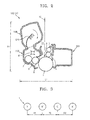
- FIGS. 4A-4B are cross-sectional views illustrating a detailed structure of a second developing device, according to exemplary embodiments of the present general inventive concept
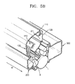
- FIG. 5A is a partial perspective view illustrating the shape of a connecting unit of a second toner containing unit and FIG. 5B is a partial perspective view illustrating a first toner containing unit without the second toner containing unit attached thereto, according to exemplary embodiments of the present general inventive concept;
- FIG. 6 is a cross-sectional view illustrating a bottom portion of a second toner containing unit, according to exemplary embodiments of the present general inventive concept
- FIG. 7 is a perspective view illustrating a second agitating member according to exemplary embodiments of the present general inventive concept
- FIG. 8 is a cross-sectional view illustrating a bottom portion of a second toner containing unit according to exemplary embodiments of the present general inventive concept.
- FIG. 9 is a perspective view illustrating a second agitating member according to exemplary embodiments of the present general inventive concept.
- FIG. 1 is a schematic structural view illustrating an electrophotographic image forming apparatus according to exemplary embodiments of the present general inventive concept.
- the electrophotographic image forming apparatus can be an electrophotographic color image forming apparatus to print a color image by using an electrophotographic method.
- FIG. 1 illustrates a plurality of photosensitive drums 1Y, 1M, 1C, and 1K, a plurality of developing devices 10Y, 10M, 10C, and 10K, and an intermediate transfer belt 30.
- Each photosensitive drum 1 is, for example, a photosensitive body having a surface on which an electrostatic latent image is formed and may include a conductive metal pipe and a photosensitive layer formed on an outer circumferential surface thereof.
- the photosensitive drums 1Y, 1M, 1C, and 1K may be collectively referred to as the photosensitive drums 1 and the developing devices 10Y, 10M, 10C, and 10K may be collectively referred to as the developing devices 10.
- the developing devices 10 may respectively correspond to the photosensitive drums 1. Each developing device 10 may form a toner image on a surface of the photosensitive drum 1 by supplying and developing toner to an electrostatic latent image formed on the photosensitive drum 1. Each of the developing devices 10 may be replaced with a new developing device, without replacing the photosensitive drums 1. In addition, the developing devices 10 may be cartridges respectively including the photosensitive drums 1.
- the developing devices 10 may include the developing device 10Y to contain a toner of yellow (Y), the developing device 10M to contain a toner of magenta (M), the developing device 10C to contain a toner of cyan (C), and the developing device 10K to contain a toner of black (K).
- the exemplary embodiments of the present general inventive concept are not limited to this case and thus the developing devices 10 may include developing devices to contain various colors such as light magenta, white, or the like in addition to the above-described colors.
- the developing devices 10 may include developing devices to contain various colors such as light magenta, white, or the like instead of one or more of the above-described colors.
- the developing devices 10 may include a developing device to contain a toner for yellow, a developing device to contain a toner for magenta, a developing device to contain a toner for white, and a developing device to contain a toner for black.
- the electrophotographic image forming apparatus includes the developing devices 10Y, 10M, 10C, and 10K will be described.
- elements marked together with Y, M, C, and K refer to elements for printing images by using toners of Y, M, C, and K colors, respectively.
- An exposer 20 may respectively form electrostatic latent images corresponding to images of Y, M, C, and K on the photosensitive drums 1Y, 1M, 1C, and 1K by irradiating light that is modulated to correspond to image information to the photosensitive drums 1Y, 1M, 1C, and 1K, which will be described later.
- Examples of the exposer 20 may include a laser scanning unit (LSU) using a laser diode as a light source, a light emitting diode (LED) exposer using an LED as a light source, and the like.
- LSU laser scanning unit
- LED light emitting diode
- the intermediate transfer belt 30 is an example of a transfer medium. Toner images of Y, M, C, and K respectively developed on the photosensitive drums 1Y, 1M, 1C, and 1K are temporally accommodated on the intermediate transfer belt 30 prior to being transferred to a recording medium P.
- the intermediate transfer belt 30 may be supported by, for example, supporting rollers 31 and 32 and may rotate around the supporting rollers 31 and 32.
- a plurality of first transfer rollers 40Y, 40M, 40C, and 40K are arranged to respectively face the photosensitive drums 1Y, 1M, 1C, and 1K, where the intermediate transfer belt 30 is interposed between the photosensitive drums 1Y, 1M, 1C, and 1K and the first transfer rollers 40.
- the first transfer rollers 40 are, for example, first transferring devices to transfer the toner images to the intermediate transfer belt 30 from the photosensitive drums 1Y, 1M, 1C, and 1K, respectively.
- An intermediate transfer bias voltage is applied to the first transfer rollers 40 by a power supply (not illustrated) so as to transfer the toner images developed on the photosensitive drums 1 to the intermediate transfer belt 30.
- the first transfer rollers 40Y, 40M, 40C, and 40K and the photosensitive drums 1Y, 1M, 1C, and 1K may be in pressing contact to each other, respectively, with the intermediate transfer belt 30 disposed therebetween.
- a corona transferring device or a pin scorotron transferring device may be used.
- a second transfer roller 50 is an example of a second transferring device to transfer the toner images from the intermediate transfer belt 30 to the recording medium P.
- the second transfer roller 50 may be disposed to face the supporting roller 31, where the intermediate transfer belt 30 is disposed between the second transfer roller 50 and the supporting roller 31.
- a transfer bias voltage is applied to the second transfer roller 50 by the power supply so as to transfer the toner images transferred to the intermediate transfer belt 30 to the recording medium P.
- the second transfer roller 50 and the supporting roller 31 may be in pressing contact to each other, with the intermediate transfer belt 30 disposed therebetween.
- a corona transferring device or a pin scorotron transferring device may be used.
- a pickup roller 71 may pick up the recording medium P on a sheet-by-sheet basis from a loading board 70.
- a set of feed rollers 72 may feed the recording medium P to a transfer region where the second transfer roller 50 and the intermediate transfer belt 30 face each other.
- the electrophotographic image forming apparatus of FIG. 1 transfers the toner images developed on the photosensitive drums 1Y, 1M, 1C, and 1K to the intermediate transfer belt 30 and then transfers the toner images to the recording medium P passing between the intermediate transfer belt 30 and the second transfer roller 50.
- the present general inventive concept is not limited to this case.
- the toner images may be directly transferred from the photosensitive drums 1Y, 1M, 1C, and 1K, respectively, to the recording medium P, without using the intermediate transfer belt 30.
- the second transfer roller 50 may not be equipped, a paper moving belt (not illustrated) to move the recording medium P while maintaining the recording medium P on a surface thereof by an electrostatic force may be used instead of the intermediate transfer belt 30, and the recording medium P may be a transfer medium.
- a fuser 60 fuses an image transferred to the recording medium P by applying heat and/or pressure to the image.
- a shape of the fuser 60 is not limited to FIG. 1 .
- the recording medium P passing through the fuser 60 is discharged by a discharge roller 73.
- FIG. 2 is a cross-sectional view illustrating a detailed structure of a developing device 10, according to exemplary embodiments of the present general inventive concept.
- the developing device 10 may include a first toner containing unit 100, a developing unit 200, and a waste toner containing unit 300.
- the first toner containing unit 100 may contain toner to provide to the developing unit 200.
- the developing unit 200 forms a toner image by supplying toner provided by the first toner containing unit 100 to an electrostatic latent image formed on a photosensitive drum 1.
- the waste toner containing unit 300 contains waste toner, impurities, or the like that is removed from a surface of the photosensitive drum 1.
- a developing roller 5 may be installed in the developing unit 200.
- the developing roller 5 supplies toner contained in the developing device 10 to the photosensitive drum 1.
- a developing bias voltage may be applied to the developing roller 5 by the power supply.
- a regulating member 6 regulates the amount of toner supplied to a developing region where the photosensitive drum 1 and the developing roller 5 face each other by the developing roller 5.
- the developing roller 5 When a dual-component developing method is used, a magnetic carrier and a toner are contained in the developing device 10, and the developing roller 5 is spaced apart from the photosensitive drum 1 by, for example, several tens to several hundreds of microns.
- the developing roller 5 may be a magnetic roller.
- the developing roller 5 may include a developing sleeve and a magnetic roller disposed in the developing sleeve.
- the toner in the developing device 10 is attached to a surface of the magnetic carrier.
- the magnetic carrier with the toner attached thereto is attached to a surface of the developing roller 5 and is moved to the developing region where the photosensitive drum 1 and the developing roller 5 face each other.
- the developing roller 5 may contact the photosensitive drum 1 and rotate. Alternatively, while the developing roller 5 rotates, the developing roller 5 may be spaced apart from the photosensitive drum 1 by, for example, several tens to several hundreds of microns.
- a supplying roller 7 to attach toner to the surface of the developing roller 5 may be installed in the developing unit 200.
- a supplying bias voltage may be applied to the supplying roller 7 by the power supply.
- An agitator 8 may be installed in the developing unit 200. The agitator 8 may agitate the toner to charge the toner with triboelectricity and may move the toner toward the supplying roller 7.
- An example of the agitator 8 may include a paddle.
- the agitator 8 may mix and agitate the toner contained in the developing unit 200 with the magnetic carrier, and may move the mixture of the toner and the magnetic carrier to the developing roller 5.
- the agitator 8 may be an auger to move the toner and the carrier in a widthwise direction W (see FIG. 5B ) of the developing device 10 and the developing unit 200 may include a plurality of agitators 8.
- a charging roller 2 charges the photosensitive drum 1 to have a uniform surface potential.
- a charging brush, a corona charger, or the like may be used.
- a charging roller cleaner 3 removes impurities such as toner, dust, or the like attached to a surface of the photosensitive drum 1, the charging roller 2, and the like.
- a cleaning blade 4 removes waste toner and impurities that remain on the surface of the photosensitive drum 1 after an intermediate transfer process is performed.
- a different type of cleaning device such as a rotatable brush or the like may be used. Waste toner and impurities removed from the surface of the photosensitive drum 1 are contained in the waste toner containing unit 300.
- the developing unit 200 and the first toner containing unit 100 are disposed at one side (e.g., a left side), and the waste toner containing unit 300 is disposed at another side (e.g., a right side).
- an optical path 11 through which the light 12 passes is formed between a set of the developing unit 200 and the first toner containing unit 100, and the waste toner containing unit 300.
- the optical path 11 extends in a vertical direction.
- the light 12 is irradiated from above the photosensitive drum 1.
- the first toner containing unit 100 may be disposed above the developing unit 200 with respect to the direction of gravity so that toner may be smoothly supplied from the first toner containing unit 100 to the developing unit 200 by gravity. With respect to a propagation/proceeding direction of the light 12, the developing unit 200 is disposed on a region downstream from the first toner containing unit 100. By disposing the first toner containing unit 100 above the developing unit 200, the amount of toner contained in the first toner containing unit 100 may be increased without increasing a length L of the electrophotographic image forming apparatus, as such arrangement of the first toner containing unit 100 does not increase a length L1 of the developing device 10.
- a first agitating member 510 may be installed in the first toner containing unit 100 so as to agitate toner and to supply the toner to the developing unit 200.
- the exposer 20 may respectively scan a plurality of light beams modulated to correspond to image information of colors to the photosensitive drums 1Y, 1M, 1C, and 1K to form electrostatic latent images.
- the developing devices 10Y, 10M, 10C, and 10K may respectively supply toners of Y, M, C, and K to the electrostatic latent images formed on the photosensitive drums 1Y, 1M, 1C, and 1K to respectively form visible toner images of Y, M, C, and K on the photosensitive drums 1Y, 1M, 1C, and 1K.
- the toner images of Y, M, C, and K are sequentially transferred to the intermediate transfer belt 30 by the intermediate transfer bias voltage applied to the first transfer rollers 40 by the power supply.
- the recording medium P loaded on the loading board 70 is moved between the second transfer roller 50 and the intermediate transfer belt 30 by the pickup roller 71 and the moving roller 72.
- the toner images of Y, M, C, and K transferred to the intermediate transfer belt 30 are transferred to the recording medium P by a transfer bias voltage applied to the second transfer roller 50 by the power supply.
- the recording medium P passes through the fuser 60, the toner images are fused onto the recording medium P by heat and pressure.
- the recording medium P on which the toner images are completely fused is discharged to a tray 74 by the discharge roller 73 from the fuser 60.
- the recording medium P When duplex printing is performed, the recording medium P, after having passed through the fuser 60 to print an image on one surface of the recoding medium P, is guided to a duplex printing path 80. Thus, the recording medium P is supplied between the intermediate transfer belt 30 and the second transfer roller 50 again. Another image is transferred to a rear surface of the recording medium P as the recording medium P passes between the intermediate transfer belt 30 and the second transfer roller 50 again. The recording medium P is discharged to the tray 74 by the discharge roller 73 after having been passed through the fuser 60 again to fuse the toner images on the rear surface of the recording medium P.
- Different colors of toners are contained in the first toner containing units 100 of the developing devices 10Y, 10M, 10C, and 10K, respectively. When the toners are exhausted, the toners need to be refilled.
- the toner of each developing device 10 may be refilled by supplying the toner to the first toner containing unit100, or changing only the first toner containing unit100, or changing the developing device 10 itself, or the like.
- one color may be more frequently used than other colors.
- a text document of a single color e.g., a black color
- the toner of the developing device 10K is refilled most frequently, and thus a replacement cycle of the developing device 10K is the shortest from among the developing devices 10Y, 10M, 10C, and 10K.
- the size of the developing device 10K needs to be increased so as to contain as large an amount of black toner as possible.
- the amount of black toner contained in the first toner containing unit 100 may be increased by extending the first toner containing unit 100 of the developing device 10K upward or in a longitudinal direction.
- a height H or the length L of the image forming apparatus may be increased due to the increased size of the first toner containing unit 100 of the developing device 10.
- toners of Y, M, C, and K are sequentially developed and transferred. When an interval P1 between the photosensitive drums 1Y and 1M, an interval P2 between the photosensitive drums 1M and 1C, and an interval P3 between the photosensitive drums 1C, and 1K are equal to one another, as illustrated in FIG.
- a point of time to begin development and transfer of the toners to the intermediate transfer belt 30 can be controlled.
- the interval P3 between the photosensitive drums 1C and 1K may be greater than each of the interval P1 between the photosensitive drums 1M and 1C and the interval P2 between the photosensitive drums 1M, and 1C, and thus it may be complicated to control a point of time to begin development and transfer of the toner to the intermediate transfer belt 30.
- the developing devices 10Y, 10M, and 10C will be referred to as first developing devices 101 and the developing device 10K will be referred to as a second developing device 102 in order to differentiate the developing devices 10Y, 10M, and 10C, and the developing device 10K.
- the photosensitive drums 1Y, 1M, and 1C may be referred to as first photosensitive drums
- the photosensitive drum 1K may be referred to as a second photosensitive drum.
- the first developing device 101 has the same structure as that illustrated in FIG. 2 .
- the second developing device 102 may be disposed on a region downstream from the first developing device 101 with respect to a direction of movement/proceeding direction A of the intermediate transfer belt 30. That is, as illustrated in FIG. 1 , the second developing device 102 is disposed on a most downstream region with respect to the direction of movement/proceeding direction A.
- FIGS. 4A and 4B An example of a structure of the second developing device 102 is illustrated in FIGS. 4A and 4B .
- the structure of the second developing device 102 of FIG. 4A may be the same as the structure of the first developing device 101 of FIG. 2 , except that the second developing device 102 of FIG. 4A further includes a second toner containing unit 400 and a connecting unit 410 to connect the second toner containing unit 400 and the first toner containing unit 100.
- the second toner containing unit 400 is disposed at the other side, that is, a side opposite to the first toner containing unit 100. Toner is contained in the second toner containing unit 400.
- the second toner containing unit 400 is disposed above the waste toner containing unit 300. That is, with respect to the propagation/proceeding direction of the light 12, the waste toner containing unit 300 is disposed on a region downstream from the second toner containing unit 400.
- the second toner containing unit 400 may be disposed in a space above the waste toner containing unit 300, thereby increasing the amount of toner contained in the second developing device 102 without increasing the length (which corresponds to 'L' of FIG. 1 ) of the image forming apparatus.
- the second toner containing unit 400 is disposed such that the height of the second toner containing unit 400 is substantially equal to the height of the first toner containing unit 100, and thus the height H2 is not increased by the second toner containing unit 400.
- FIG. 5A is a partial perspective view to illustrate the shape of the connecting unit 410, according to an embodiment of the present general inventive concept.
- the connecting unit 410 is disposed in a region outside an effective width W1 of the optical path 11.
- connecting units 410 may be disposed in two regions outside the effective width W1 of the optical path 11 (as illustrated in FIG. 6 ).
- the connecting unit 410 may be disposed on only one region outside the effective width W1 of the optical path 11 (as illustrated in FIG. 8 ).
- a second agitating member 520 may be installed in the second toner containing unit 400.
- the second agitating member 520 may include a rotation axis member 521 with a rotation axis 521 a and an agitating wing 522 that extends in a radial direction of the rotation axis member 521.
- the agitating wing 522 may be made of a flexible material, so has, for example, a flexible film type of material. A length of the agitating wing 522 in the radial direction is determined such that the agitating wing 522 may flexibly contact an inner wall of the second toner containing unit 400 so as to move the toner in the second toner containing unit.
- the rotation axis member 521 extends in a width direction of the second toner containing unit 400.
- toner contained in the second toner containing unit 400 may be moved to the first toner containing unit 100 through the connecting unit 410 by the agitating wing 522.
- at least a bottom portion 411 of the connecting unit 410 may be inclined downwards in a direction from the second toner containing unit 400 toward the first toner containing unit 100.
- the second agitating member 520 including the agitating wing 522 which extends from the rotation axis 521 in the radial direction, moves the toners contained in the second toner containing unit 400 in a longitudinal direction of the second toner containing unit 400, but does not move the toner in a width direction of the second toner containing unit 400.
- a separate mover may be disposed in the second toner containing unit 400 to move the toner in the width direction of the second toner containing unit 400.
- the toner may be moved in the width direction by the shape of the second toner containing unit 400 without using any separate mover, as described below.
- FIG. 4B illustrates an exemplary embodiment of the second developing device 102, where the second toner containing unit 400 is detachable from the first toner containing unit 100.
- one end of the connecting unit 410 facing with an opening may be detachably connected to the first toner containing unit 100.
- the second developing device 102 may have the same structure as the first developing device 101, having only the first toner containing unit 100.
- the image forming apparatus may be provided with developing devices with only the first toner containing units 100, where each of the first toner containing units 100 can receive the second toner containing unit 400 via a receiving portion 110 to attach the second toner containing unit 400.
- the second toner containing unit 400 may be attached or detached to the first toner containing unit 100, depending on whether the color of the toner for the developing device is frequently used. For example, if it is determined that yellow color is used frequently, then a user can attach a second toner containing unit 400 for the yellow color to the first toner containing unit 100 in the developing device 10Y for the yellow color. This provides flexibility by enabling a user to vary toner container capacities for different colors, depending on which color is more used.
- the receiving portion 110 of the first toner containing unit 100 and the connecting portion 410 of the second toner containing unit 400 may be provided with an engaging mechanism (e.g., a notch and a groove) to firmly engage the second toner containing unit 400 with the first toner containing unit 100.
- an engaging mechanism e.g., a notch and a groove
- FIG. 5B is a partial perspective view illustrating a first toner containing unit without the second toner containing unit attached thereto.
- FIG. 5B may be an exemplary embodiment of the second developing device 102 with the second toner containing unit 400 detached from the first toner containing unit 100.
- FIG. 5B may be an exemplary embodiment of the first developing device 101 having only the first toner containing unit 100.
- the first toner containing unit 100 and the developing unit 200 disposed under the first toner containing unit 100 are disposed in one side, and the waste toner containing unit 300 is disposed in the other side, and the photosensitive drum 1 is disposed between the developing unit 200 and the waste toner containing unit 300.
- the first toner containing unit 100 has the first agitating member 510 to agitate toner and to supply the toner to the developing unit 200.
- the first toner containing unit 100 may have the receiving portion 110 to receive a connecting portion 410 of the second toner containing unit 400 to attach the second toner containing unit 400 to the first toner containing unit 100.
- a cap 120 may be placed to cover the receiving portion 110.
- the developing unit 200 has the agitator 8 that may be an auger to move the toner and the carrier in a widthwise direction W of the developing device.
- FIG. 6 illustrates a cross-sectional view of the second toner containing unit 400 taken along a line Y-Y' of FIG. 4A , according to an embodiment of the present general inventive concept.
- connecting units 410 are disposed in two regions R1 and R1 outside the effective width W1 of the optical path 11.
- the bottom portion 401 of the second toner containing unit 400 is inclined downward from a central portion thereof toward two lateral portions corresponding to the two regions R1 and R1, that is, toward the connecting units 410.
- the second agitating member 520 rotates in the second toner containing unit 400, the toner may flow via the second toner containing unit 400.
- Toner is a very small particle and may have high liquidity.
- the toner that flows due to the second agitating member 520 may flow toward the two lateral portions where the connection units 410 are positioned, according to the inclination of the bottom portion 401 and a force of gravity. Since toner has high fluidity, the toner may easily flow toward the two lateral portions by using only a small inclination, such as an inclination of about 2 to about 3 mm from the central portion.
- the inclination of the bottom portion 401 may be shaped like a straight line shape or a curve line shape.
- the connecting units 410 when the connecting units 410 are disposed in the two lateral portions of the second toner containing unit 400, toner contained in the second toner containing unit 400 may be easily moved to the first toner containing unit 100 through the connecting units 410 by using the second agitating member 520 including the agitating wing 522 extending from the rotation axis member 521 in the radial direction.
- the agitating wing 522 may include a first wing portion 523 and a second wing portion 524 next to the connecting units 410 to correspond with the connecting units 410, respectively.
- the length of the second wing portion 524 in the radial direction is greater than the length of the first wing portion 523 in the radial direction.
- the bottom portion 401 may be inclined downward from the other lateral portion toward the connecting unit 410.
- the second agitating member 520 may be configured such that the second wing portion 524 may be formed in one region only.
- the volume of the waste toner containing unit 300 may be smaller than the volume of the first toner containing unit 100.
- the waste toner containing unit 300 may occupy a space at almost the same level as the developing unit 200 in a vertical direction.
- a space above the waste toner containing unit 300 that is, a space next to the first toner containing unit 100, may correspond to a spare space.
- the second toner containing unit 400 is disposed in the spare space and is connected to the first toner containing unit 100 by the connecting unit 410, thereby increasing the amount of toner contained in the second developing device 102 without increasing the size of the image forming apparatus.
- the second toner containing unit 400 is formed such that a length L1 (refer to FIG. 2 ) of the first developing device 101 may be equal to a length L2 of the second developing device 102, the total length L (refer to FIG. 1 ) of the image forming apparatus is not changed by the second toner containing unit 400.
- a height H1 (refer to FIG.
- the total height H (refer to FIG. 1 ) of the image forming apparatus is not changed by the second toner containing unit 400.
- the second toner containing unit 400 may further extend in a longitudinal direction, as indicated by dotted lines of FIG. 4A . That is, a length L2' of the second developing device 102 may be greater than the length L1 (refer to FIG. 2 ) of the first developing device 101. In this case, a position of the photosensitive drum 1K is not changed and only the second toner containing unit 400 extends in the longitudinal direction.
- the second developing device 102 since the second developing device 102 is disposed on a region downstream from the first developing device 101 with respect to the direction of movement/proceeding direction A of the intermediate transfer belt 30, although the position of the second toner containing unit 400 extends in the longitudinal direction, the position of the photosensitive drum 1K may not be changed.
- the intervals P1, P2, and P3 between the photosensitive drums 1Y, 1M, 1C, and 1K may be maintained to be equal to each other.
- the waste toner containing unit 300 may be extended in a longitudinal direction, as indicated by dotted lines of FIG. 4A , to an extent that the second toner containing unit 400 is extended.
Landscapes
- Physics & Mathematics (AREA)
- General Physics & Mathematics (AREA)
- Color Electrophotography (AREA)
- Dry Development In Electrophotography (AREA)
- Electrophotography Configuration And Component (AREA)
Applications Claiming Priority (1)
| Application Number | Priority Date | Filing Date | Title |
|---|---|---|---|
| KR1020110120319A KR101580841B1 (ko) | 2011-11-17 | 2011-11-17 | 현상기 및 이를 채용한 전자사진방식 화상형성장치 |
Publications (3)
| Publication Number | Publication Date |
|---|---|
| EP2595002A2 true EP2595002A2 (de) | 2013-05-22 |
| EP2595002A3 EP2595002A3 (de) | 2013-08-28 |
| EP2595002B1 EP2595002B1 (de) | 2019-03-06 |
Family
ID=46880949
Family Applications (1)
| Application Number | Title | Priority Date | Filing Date |
|---|---|---|---|
| EP12180876.0A Active EP2595002B1 (de) | 2011-11-17 | 2012-08-17 | Entwicklungsvorrichtung und elektrofotografische Bilderzeugungsvorrichtung damit |
Country Status (6)
| Country | Link |
|---|---|
| US (1) | US8983341B2 (de) |
| EP (1) | EP2595002B1 (de) |
| KR (1) | KR101580841B1 (de) |
| CN (2) | CN105116703B (de) |
| DE (1) | DE202012012886U1 (de) |
| ES (1) | ES2716861T3 (de) |
Families Citing this family (5)
| Publication number | Priority date | Publication date | Assignee | Title |
|---|---|---|---|---|
| KR20100047675A (ko) * | 2008-10-29 | 2010-05-10 | 삼성전자주식회사 | 피대전체용 대전부재 조립체 및 이를 구비한 화상형성장치용 대전장치 |
| DK3226075T3 (en) * | 2011-08-19 | 2018-12-10 | Hewlett Packard Development Co | TONER CONTAINER |
| JP2018081257A (ja) * | 2016-11-18 | 2018-05-24 | キヤノン株式会社 | 画像形成装置 |
| JP7530567B2 (ja) * | 2020-09-18 | 2024-08-08 | 株式会社リコー | 保持装置、プロセスカートリッジ、及び、画像形成装置 |
| US11226586B1 (en) * | 2020-09-24 | 2022-01-18 | Toshiba Tec Kabushiki Kaisha | Image forming apparatus and processing method |
Family Cites Families (29)
| Publication number | Priority date | Publication date | Assignee | Title |
|---|---|---|---|---|
| US6249664B1 (en) * | 1998-06-29 | 2001-06-19 | Konica Corporation | Developing apparatus having two rotors for agitating and conveying developer |
| CA2300651C (en) * | 1999-03-17 | 2002-12-10 | Canon Kabushiki Kaisha | Toner container and toner replenishing mechanism |
| JP2001183886A (ja) | 1999-12-24 | 2001-07-06 | Canon Inc | 画像形成装置 |
| JP4672893B2 (ja) | 2001-03-30 | 2011-04-20 | キヤノン株式会社 | 現像剤補給容器、及び画像形成装置 |
| DE60312426T2 (de) | 2002-04-24 | 2007-11-29 | Canon K.K. | Entwicklerzufuhrbehälter |
| JP2004077799A (ja) | 2002-08-19 | 2004-03-11 | Brother Ind Ltd | 画像形成装置 |
| JP4259074B2 (ja) * | 2002-09-17 | 2009-04-30 | 富士ゼロックス株式会社 | 現像剤補給装置および画像形成装置 |
| JP2006030957A (ja) * | 2004-06-16 | 2006-02-02 | Canon Inc | 画像形成装置 |
| RU2407049C2 (ru) * | 2004-11-24 | 2010-12-20 | Кэнон Кабусики Кайся | Контейнер подачи проявителя |
| US8190068B2 (en) * | 2005-03-04 | 2012-05-29 | Canon Kabushiki Kaisha | Developer supply container with mounting attitude regulation and drive receiving member rotation suppression features |
| JP4715263B2 (ja) * | 2005-03-25 | 2011-07-06 | 富士ゼロックス株式会社 | クリーニング装置及びこれを用いたプロセスカートリッジ並びに画像形成装置 |
| JP4641937B2 (ja) * | 2005-12-27 | 2011-03-02 | シャープ株式会社 | トナー補給装置を備えた画像形成装置 |
| CN101395542B (zh) * | 2006-03-10 | 2012-01-04 | 佳能株式会社 | 处理盒、显影剂供给盒以及电子照相成像装置 |
| JP4378374B2 (ja) | 2006-03-10 | 2009-12-02 | キヤノン株式会社 | プロセスカートリッジ、現像剤補給カートリッジ、及び電子写真画像形成装置 |
| JP4402066B2 (ja) * | 2006-03-20 | 2010-01-20 | シャープ株式会社 | トナー補給装置、現像装置および画像形成装置 |
| JP4437476B2 (ja) * | 2006-03-28 | 2010-03-24 | シャープ株式会社 | トナー補給装置、画像形成装置及びトナー補給方法 |
| JP4946157B2 (ja) * | 2006-05-02 | 2012-06-06 | 富士ゼロックス株式会社 | 画像形成ユニット |
| JP4802872B2 (ja) * | 2006-06-08 | 2011-10-26 | 富士ゼロックス株式会社 | 着脱カートリッジおよび画像形成装置 |
| JP4420915B2 (ja) * | 2006-10-16 | 2010-02-24 | シャープ株式会社 | トナー搬送装置、トナー補給装置およびこれらを用いた画像形成装置 |
| JP5067865B2 (ja) * | 2007-02-21 | 2012-11-07 | キヤノン株式会社 | 現像剤補給容器及び画像形成装置 |
| JP4948489B2 (ja) | 2007-08-10 | 2012-06-06 | キヤノン株式会社 | 画像形成装置 |
| EP2034370B1 (de) * | 2007-09-04 | 2018-06-13 | Kabushiki Kaisha Toshiba | Tonerkartusche und Bilderzeugungsvorrichtung mit Tonerkartusche |
| KR101269467B1 (ko) * | 2008-01-09 | 2013-05-30 | 삼성전자주식회사 | 화상형성장치 |
| KR100891117B1 (ko) * | 2008-03-03 | 2009-03-30 | 삼성전자주식회사 | 화상형성장치 및 현상제 수용부재 |
| JP4661916B2 (ja) * | 2008-07-25 | 2011-03-30 | ブラザー工業株式会社 | 画像形成装置 |
| JP4371177B1 (ja) * | 2009-03-11 | 2009-11-25 | 富士ゼロックス株式会社 | 像形成剤収容容器、画像形成装置、像形成剤収容容器の装着方法、像形成剤収容容器の取り出し方法、及び像形成剤の充填方法 |
| JP4918127B2 (ja) * | 2009-11-04 | 2012-04-18 | 株式会社沖データ | 現像剤収容器、現像装置及び画像形成装置 |
| JP4556248B1 (ja) | 2010-03-10 | 2010-10-06 | 富士ゼロックス株式会社 | 像形成剤収容容器、画像形成装置、及び像形成剤の充填方法 |
| JP5998430B2 (ja) * | 2011-04-26 | 2016-09-28 | 富士ゼロックス株式会社 | 画像形成装置 |
-
2011
- 2011-11-17 KR KR1020110120319A patent/KR101580841B1/ko active Active
-
2012
- 2012-07-31 US US13/562,348 patent/US8983341B2/en active Active
- 2012-08-17 EP EP12180876.0A patent/EP2595002B1/de active Active
- 2012-08-17 DE DE202012012886.8U patent/DE202012012886U1/de not_active Expired - Lifetime
- 2012-08-17 ES ES12180876T patent/ES2716861T3/es active Active
- 2012-10-10 CN CN201510603920.7A patent/CN105116703B/zh active Active
- 2012-10-10 CN CN201210382426.9A patent/CN103123447B/zh active Active
Non-Patent Citations (1)
| Title |
|---|
| None |
Also Published As
| Publication number | Publication date |
|---|---|
| CN103123447A (zh) | 2013-05-29 |
| KR20130054747A (ko) | 2013-05-27 |
| KR101580841B1 (ko) | 2015-12-30 |
| CN105116703A (zh) | 2015-12-02 |
| US8983341B2 (en) | 2015-03-17 |
| CN105116703B (zh) | 2019-10-01 |
| EP2595002A3 (de) | 2013-08-28 |
| CN103123447B (zh) | 2015-10-28 |
| DE202012012886U1 (de) | 2014-02-11 |
| US20130129389A1 (en) | 2013-05-23 |
| EP2595002B1 (de) | 2019-03-06 |
| ES2716861T3 (es) | 2019-06-17 |
Similar Documents
| Publication | Publication Date | Title |
|---|---|---|
| US8422921B2 (en) | Image forming apparatus and developer container therefor | |
| JP2016206330A (ja) | 現像装置及び画像形成装置 | |
| EP2595002B1 (de) | Entwicklungsvorrichtung und elektrofotografische Bilderzeugungsvorrichtung damit | |
| US10126679B2 (en) | Developing casing of a developing unit for an electrophotographic image forming apparatus having a developer collection inlet to collect developer moving along a discharge path | |
| JP4513854B2 (ja) | 現像装置および画像形成装置 | |
| JP6056166B2 (ja) | 帯電器、像形成構造体、および画像形成装置 | |
| JP2010078669A (ja) | 現像装置、プロセスカートリッジ及び画像形成装置 | |
| EP1731972B1 (de) | Entwicklungskartusche und elektrofotografische Bilderzeugungsvorrichtung damit | |
| EP1757995A1 (de) | Entwickler und elektrofotografisches Bilderzeugungsgerät damit | |
| US7949286B2 (en) | Development cartridge and electrophotographic image forming apparatus using the same | |
| JP2010054575A (ja) | 現像装置、プロセスカートリッジ及び画像形成装置 | |
| JP2006078633A (ja) | 画像形成装置 | |
| JP6634754B2 (ja) | 現像剤搬送装置及び画像形成装置 | |
| JP2013214107A (ja) | 現像装置、プロセスカートリッジ及び画像形成装置 | |
| JP2013068769A (ja) | 現像装置および画像形成装置 |
Legal Events
| Date | Code | Title | Description |
|---|---|---|---|
| PUAI | Public reference made under article 153(3) epc to a published international application that has entered the european phase |
Free format text: ORIGINAL CODE: 0009012 |
|
| AK | Designated contracting states |
Kind code of ref document: A2 Designated state(s): AL AT BE BG CH CY CZ DE DK EE ES FI FR GB GR HR HU IE IS IT LI LT LU LV MC MK MT NL NO PL PT RO RS SE SI SK SM TR |
|
| AX | Request for extension of the european patent |
Extension state: BA ME |
|
| PUAL | Search report despatched |
Free format text: ORIGINAL CODE: 0009013 |
|
| AK | Designated contracting states |
Kind code of ref document: A3 Designated state(s): AL AT BE BG CH CY CZ DE DK EE ES FI FR GB GR HR HU IE IS IT LI LT LU LV MC MK MT NL NO PL PT RO RS SE SI SK SM TR |
|
| AX | Request for extension of the european patent |
Extension state: BA ME |
|
| RIC1 | Information provided on ipc code assigned before grant |
Ipc: G03G 15/01 20060101ALI20130724BHEP Ipc: G03G 21/16 20060101AFI20130724BHEP Ipc: G03G 15/08 20060101ALI20130724BHEP |
|
| 17P | Request for examination filed |
Effective date: 20140114 |
|
| RBV | Designated contracting states (corrected) |
Designated state(s): AL AT BE BG CH CY CZ DE DK EE ES FI FR GB GR HR HU IE IS IT LI LT LU LV MC MK MT NL NO PL PT RO RS SE SI SK SM TR |
|
| 17Q | First examination report despatched |
Effective date: 20140721 |
|
| RAP1 | Party data changed (applicant data changed or rights of an application transferred) |
Owner name: S-PRINTING SOLUTION CO., LTD. |
|
| RAP1 | Party data changed (applicant data changed or rights of an application transferred) |
Owner name: HP PRINTING KOREA CO., LTD. |
|
| STAA | Information on the status of an ep patent application or granted ep patent |
Free format text: STATUS: EXAMINATION IS IN PROGRESS |
|
| GRAP | Despatch of communication of intention to grant a patent |
Free format text: ORIGINAL CODE: EPIDOSNIGR1 |
|
| STAA | Information on the status of an ep patent application or granted ep patent |
Free format text: STATUS: GRANT OF PATENT IS INTENDED |
|
| INTG | Intention to grant announced |
Effective date: 20181214 |
|
| GRAS | Grant fee paid |
Free format text: ORIGINAL CODE: EPIDOSNIGR3 |
|
| GRAA | (expected) grant |
Free format text: ORIGINAL CODE: 0009210 |
|
| STAA | Information on the status of an ep patent application or granted ep patent |
Free format text: STATUS: THE PATENT HAS BEEN GRANTED |
|
| AK | Designated contracting states |
Kind code of ref document: B1 Designated state(s): AL AT BE BG CH CY CZ DE DK EE ES FI FR GB GR HR HU IE IS IT LI LT LU LV MC MK MT NL NO PL PT RO RS SE SI SK SM TR |
|
| REG | Reference to a national code |
Ref country code: GB Ref legal event code: FG4D |
|
| REG | Reference to a national code |
Ref country code: CH Ref legal event code: EP Ref country code: AT Ref legal event code: REF Ref document number: 1105357 Country of ref document: AT Kind code of ref document: T Effective date: 20190315 |
|
| REG | Reference to a national code |
Ref country code: DE Ref legal event code: R096 Ref document number: 602012057375 Country of ref document: DE |
|
| REG | Reference to a national code |
Ref country code: IE Ref legal event code: FG4D |
|
| REG | Reference to a national code |
Ref country code: NL Ref legal event code: FP |
|
| REG | Reference to a national code |
Ref country code: ES Ref legal event code: FG2A Ref document number: 2716861 Country of ref document: ES Kind code of ref document: T3 Effective date: 20190617 |
|
| REG | Reference to a national code |
Ref country code: LT Ref legal event code: MG4D |
|
| PG25 | Lapsed in a contracting state [announced via postgrant information from national office to epo] |
Ref country code: NO Free format text: LAPSE BECAUSE OF FAILURE TO SUBMIT A TRANSLATION OF THE DESCRIPTION OR TO PAY THE FEE WITHIN THE PRESCRIBED TIME-LIMIT Effective date: 20190606 Ref country code: FI Free format text: LAPSE BECAUSE OF FAILURE TO SUBMIT A TRANSLATION OF THE DESCRIPTION OR TO PAY THE FEE WITHIN THE PRESCRIBED TIME-LIMIT Effective date: 20190306 Ref country code: LT Free format text: LAPSE BECAUSE OF FAILURE TO SUBMIT A TRANSLATION OF THE DESCRIPTION OR TO PAY THE FEE WITHIN THE PRESCRIBED TIME-LIMIT Effective date: 20190306 Ref country code: SE Free format text: LAPSE BECAUSE OF FAILURE TO SUBMIT A TRANSLATION OF THE DESCRIPTION OR TO PAY THE FEE WITHIN THE PRESCRIBED TIME-LIMIT Effective date: 20190306 |
|
| PG25 | Lapsed in a contracting state [announced via postgrant information from national office to epo] |
Ref country code: LV Free format text: LAPSE BECAUSE OF FAILURE TO SUBMIT A TRANSLATION OF THE DESCRIPTION OR TO PAY THE FEE WITHIN THE PRESCRIBED TIME-LIMIT Effective date: 20190306 Ref country code: RS Free format text: LAPSE BECAUSE OF FAILURE TO SUBMIT A TRANSLATION OF THE DESCRIPTION OR TO PAY THE FEE WITHIN THE PRESCRIBED TIME-LIMIT Effective date: 20190306 Ref country code: HR Free format text: LAPSE BECAUSE OF FAILURE TO SUBMIT A TRANSLATION OF THE DESCRIPTION OR TO PAY THE FEE WITHIN THE PRESCRIBED TIME-LIMIT Effective date: 20190306 Ref country code: GR Free format text: LAPSE BECAUSE OF FAILURE TO SUBMIT A TRANSLATION OF THE DESCRIPTION OR TO PAY THE FEE WITHIN THE PRESCRIBED TIME-LIMIT Effective date: 20190607 Ref country code: BG Free format text: LAPSE BECAUSE OF FAILURE TO SUBMIT A TRANSLATION OF THE DESCRIPTION OR TO PAY THE FEE WITHIN THE PRESCRIBED TIME-LIMIT Effective date: 20190606 |
|
| REG | Reference to a national code |
Ref country code: AT Ref legal event code: MK05 Ref document number: 1105357 Country of ref document: AT Kind code of ref document: T Effective date: 20190306 |
|
| PG25 | Lapsed in a contracting state [announced via postgrant information from national office to epo] |
Ref country code: EE Free format text: LAPSE BECAUSE OF FAILURE TO SUBMIT A TRANSLATION OF THE DESCRIPTION OR TO PAY THE FEE WITHIN THE PRESCRIBED TIME-LIMIT Effective date: 20190306 Ref country code: CZ Free format text: LAPSE BECAUSE OF FAILURE TO SUBMIT A TRANSLATION OF THE DESCRIPTION OR TO PAY THE FEE WITHIN THE PRESCRIBED TIME-LIMIT Effective date: 20190306 Ref country code: RO Free format text: LAPSE BECAUSE OF FAILURE TO SUBMIT A TRANSLATION OF THE DESCRIPTION OR TO PAY THE FEE WITHIN THE PRESCRIBED TIME-LIMIT Effective date: 20190306 Ref country code: SK Free format text: LAPSE BECAUSE OF FAILURE TO SUBMIT A TRANSLATION OF THE DESCRIPTION OR TO PAY THE FEE WITHIN THE PRESCRIBED TIME-LIMIT Effective date: 20190306 Ref country code: PT Free format text: LAPSE BECAUSE OF FAILURE TO SUBMIT A TRANSLATION OF THE DESCRIPTION OR TO PAY THE FEE WITHIN THE PRESCRIBED TIME-LIMIT Effective date: 20190706 Ref country code: AL Free format text: LAPSE BECAUSE OF FAILURE TO SUBMIT A TRANSLATION OF THE DESCRIPTION OR TO PAY THE FEE WITHIN THE PRESCRIBED TIME-LIMIT Effective date: 20190306 |
|
| REG | Reference to a national code |
Ref country code: ES Ref legal event code: PC2A Owner name: HEWLETT-PACKARD DEVELOPMENT COMPANY, L.P. Effective date: 20191105 |
|
| REG | Reference to a national code |
Ref country code: NL Ref legal event code: PD Owner name: HEWLETT-PACKARD DEVELOPMENT COMPANY, L.P.; US Free format text: DETAILS ASSIGNMENT: CHANGE OF OWNER(S), CHANGE OF LEGAL ENTITY; FORMER OWNER NAME: HP PRINTING KOREA CO., LTD. Effective date: 20191030 |
|
| PG25 | Lapsed in a contracting state [announced via postgrant information from national office to epo] |
Ref country code: PL Free format text: LAPSE BECAUSE OF FAILURE TO SUBMIT A TRANSLATION OF THE DESCRIPTION OR TO PAY THE FEE WITHIN THE PRESCRIBED TIME-LIMIT Effective date: 20190306 Ref country code: SM Free format text: LAPSE BECAUSE OF FAILURE TO SUBMIT A TRANSLATION OF THE DESCRIPTION OR TO PAY THE FEE WITHIN THE PRESCRIBED TIME-LIMIT Effective date: 20190306 |
|
| REG | Reference to a national code |
Ref country code: DE Ref legal event code: R097 Ref document number: 602012057375 Country of ref document: DE |
|
| REG | Reference to a national code |
Ref country code: DE Ref legal event code: R082 Ref document number: 602012057375 Country of ref document: DE Representative=s name: SCHOPPE, ZIMMERMANN, STOECKELER, ZINKLER, SCHE, DE Ref country code: DE Ref legal event code: R081 Ref document number: 602012057375 Country of ref document: DE Owner name: HEWLETT-PACKARD DEVELOPMENT COMPANY, L.P., SPR, US Free format text: FORMER OWNER: HP PRINTING KOREA CO., LTD., SUWON-SI, GYEONGGI-DO, KR |
|
| PG25 | Lapsed in a contracting state [announced via postgrant information from national office to epo] |
Ref country code: AT Free format text: LAPSE BECAUSE OF FAILURE TO SUBMIT A TRANSLATION OF THE DESCRIPTION OR TO PAY THE FEE WITHIN THE PRESCRIBED TIME-LIMIT Effective date: 20190306 Ref country code: IS Free format text: LAPSE BECAUSE OF FAILURE TO SUBMIT A TRANSLATION OF THE DESCRIPTION OR TO PAY THE FEE WITHIN THE PRESCRIBED TIME-LIMIT Effective date: 20190706 |
|
| PLBE | No opposition filed within time limit |
Free format text: ORIGINAL CODE: 0009261 |
|
| STAA | Information on the status of an ep patent application or granted ep patent |
Free format text: STATUS: NO OPPOSITION FILED WITHIN TIME LIMIT |
|
| PG25 | Lapsed in a contracting state [announced via postgrant information from national office to epo] |
Ref country code: DK Free format text: LAPSE BECAUSE OF FAILURE TO SUBMIT A TRANSLATION OF THE DESCRIPTION OR TO PAY THE FEE WITHIN THE PRESCRIBED TIME-LIMIT Effective date: 20190306 |
|
| 26N | No opposition filed |
Effective date: 20191209 |
|
| PG25 | Lapsed in a contracting state [announced via postgrant information from national office to epo] |
Ref country code: SI Free format text: LAPSE BECAUSE OF FAILURE TO SUBMIT A TRANSLATION OF THE DESCRIPTION OR TO PAY THE FEE WITHIN THE PRESCRIBED TIME-LIMIT Effective date: 20190306 |
|
| PG25 | Lapsed in a contracting state [announced via postgrant information from national office to epo] |
Ref country code: TR Free format text: LAPSE BECAUSE OF FAILURE TO SUBMIT A TRANSLATION OF THE DESCRIPTION OR TO PAY THE FEE WITHIN THE PRESCRIBED TIME-LIMIT Effective date: 20190306 |
|
| PG25 | Lapsed in a contracting state [announced via postgrant information from national office to epo] |
Ref country code: CH Free format text: LAPSE BECAUSE OF NON-PAYMENT OF DUE FEES Effective date: 20190831 Ref country code: LU Free format text: LAPSE BECAUSE OF NON-PAYMENT OF DUE FEES Effective date: 20190817 Ref country code: LI Free format text: LAPSE BECAUSE OF NON-PAYMENT OF DUE FEES Effective date: 20190831 Ref country code: MC Free format text: LAPSE BECAUSE OF FAILURE TO SUBMIT A TRANSLATION OF THE DESCRIPTION OR TO PAY THE FEE WITHIN THE PRESCRIBED TIME-LIMIT Effective date: 20190306 |
|
| REG | Reference to a national code |
Ref country code: BE Ref legal event code: MM Effective date: 20190831 |
|
| PG25 | Lapsed in a contracting state [announced via postgrant information from national office to epo] |
Ref country code: IE Free format text: LAPSE BECAUSE OF NON-PAYMENT OF DUE FEES Effective date: 20190817 |
|
| PG25 | Lapsed in a contracting state [announced via postgrant information from national office to epo] |
Ref country code: BE Free format text: LAPSE BECAUSE OF NON-PAYMENT OF DUE FEES Effective date: 20190831 |
|
| REG | Reference to a national code |
Ref country code: GB Ref legal event code: 732E Free format text: REGISTERED BETWEEN 20200917 AND 20200923 |
|
| PG25 | Lapsed in a contracting state [announced via postgrant information from national office to epo] |
Ref country code: CY Free format text: LAPSE BECAUSE OF FAILURE TO SUBMIT A TRANSLATION OF THE DESCRIPTION OR TO PAY THE FEE WITHIN THE PRESCRIBED TIME-LIMIT Effective date: 20190306 |
|
| PG25 | Lapsed in a contracting state [announced via postgrant information from national office to epo] |
Ref country code: MT Free format text: LAPSE BECAUSE OF FAILURE TO SUBMIT A TRANSLATION OF THE DESCRIPTION OR TO PAY THE FEE WITHIN THE PRESCRIBED TIME-LIMIT Effective date: 20190306 Ref country code: HU Free format text: LAPSE BECAUSE OF FAILURE TO SUBMIT A TRANSLATION OF THE DESCRIPTION OR TO PAY THE FEE WITHIN THE PRESCRIBED TIME-LIMIT; INVALID AB INITIO Effective date: 20120817 |
|
| PG25 | Lapsed in a contracting state [announced via postgrant information from national office to epo] |
Ref country code: MK Free format text: LAPSE BECAUSE OF FAILURE TO SUBMIT A TRANSLATION OF THE DESCRIPTION OR TO PAY THE FEE WITHIN THE PRESCRIBED TIME-LIMIT Effective date: 20190306 |
|
| REG | Reference to a national code |
Ref country code: DE Ref legal event code: R082 Ref document number: 602012057375 Country of ref document: DE Representative=s name: NOVAGRAAF BREVETS, FR |
|
| PGFP | Annual fee paid to national office [announced via postgrant information from national office to epo] |
Ref country code: NL Payment date: 20250723 Year of fee payment: 14 |
|
| PGFP | Annual fee paid to national office [announced via postgrant information from national office to epo] |
Ref country code: ES Payment date: 20250901 Year of fee payment: 14 |
|
| PGFP | Annual fee paid to national office [announced via postgrant information from national office to epo] |
Ref country code: DE Payment date: 20250724 Year of fee payment: 14 |
|
| PGFP | Annual fee paid to national office [announced via postgrant information from national office to epo] |
Ref country code: IT Payment date: 20250723 Year of fee payment: 14 |
|
| PGFP | Annual fee paid to national office [announced via postgrant information from national office to epo] |
Ref country code: GB Payment date: 20250724 Year of fee payment: 14 |
|
| PGFP | Annual fee paid to national office [announced via postgrant information from national office to epo] |
Ref country code: FR Payment date: 20250725 Year of fee payment: 14 |