EP2594784A2 - Éolienne verticale et pale de rotor pour celle-ci - Google Patents
Éolienne verticale et pale de rotor pour celle-ci Download PDFInfo
- Publication number
- EP2594784A2 EP2594784A2 EP12192863.4A EP12192863A EP2594784A2 EP 2594784 A2 EP2594784 A2 EP 2594784A2 EP 12192863 A EP12192863 A EP 12192863A EP 2594784 A2 EP2594784 A2 EP 2594784A2
- Authority
- EP
- European Patent Office
- Prior art keywords
- profile
- rotor
- rotor blade
- blade
- resistance
- Prior art date
- Legal status (The legal status is an assumption and is not a legal conclusion. Google has not performed a legal analysis and makes no representation as to the accuracy of the status listed.)
- Withdrawn
Links
Images


Classifications
-
- F—MECHANICAL ENGINEERING; LIGHTING; HEATING; WEAPONS; BLASTING
- F03—MACHINES OR ENGINES FOR LIQUIDS; WIND, SPRING, OR WEIGHT MOTORS; PRODUCING MECHANICAL POWER OR A REACTIVE PROPULSIVE THRUST, NOT OTHERWISE PROVIDED FOR
- F03D—WIND MOTORS
- F03D3/00—Wind motors with rotation axis substantially perpendicular to the air flow entering the rotor
- F03D3/06—Rotors
- F03D3/061—Rotors characterised by their aerodynamic shape, e.g. aerofoil profiles
-
- F—MECHANICAL ENGINEERING; LIGHTING; HEATING; WEAPONS; BLASTING
- F03—MACHINES OR ENGINES FOR LIQUIDS; WIND, SPRING, OR WEIGHT MOTORS; PRODUCING MECHANICAL POWER OR A REACTIVE PROPULSIVE THRUST, NOT OTHERWISE PROVIDED FOR
- F03D—WIND MOTORS
- F03D3/00—Wind motors with rotation axis substantially perpendicular to the air flow entering the rotor
- F03D3/005—Wind motors with rotation axis substantially perpendicular to the air flow entering the rotor the axis being vertical
-
- F—MECHANICAL ENGINEERING; LIGHTING; HEATING; WEAPONS; BLASTING
- F05—INDEXING SCHEMES RELATING TO ENGINES OR PUMPS IN VARIOUS SUBCLASSES OF CLASSES F01-F04
- F05B—INDEXING SCHEME RELATING TO WIND, SPRING, WEIGHT, INERTIA OR LIKE MOTORS, TO MACHINES OR ENGINES FOR LIQUIDS COVERED BY SUBCLASSES F03B, F03D AND F03G
- F05B2240/00—Components
- F05B2240/20—Rotors
- F05B2240/21—Rotors for wind turbines
- F05B2240/211—Rotors for wind turbines with vertical axis
- F05B2240/214—Rotors for wind turbines with vertical axis of the Musgrove or "H"-type
-
- F—MECHANICAL ENGINEERING; LIGHTING; HEATING; WEAPONS; BLASTING
- F05—INDEXING SCHEMES RELATING TO ENGINES OR PUMPS IN VARIOUS SUBCLASSES OF CLASSES F01-F04
- F05B—INDEXING SCHEME RELATING TO WIND, SPRING, WEIGHT, INERTIA OR LIKE MOTORS, TO MACHINES OR ENGINES FOR LIQUIDS COVERED BY SUBCLASSES F03B, F03D AND F03G
- F05B2240/00—Components
- F05B2240/20—Rotors
- F05B2240/30—Characteristics of rotor blades, i.e. of any element transforming dynamic fluid energy to or from rotational energy and being attached to a rotor
- F05B2240/301—Cross-section characteristics
-
- F—MECHANICAL ENGINEERING; LIGHTING; HEATING; WEAPONS; BLASTING
- F05—INDEXING SCHEMES RELATING TO ENGINES OR PUMPS IN VARIOUS SUBCLASSES OF CLASSES F01-F04
- F05B—INDEXING SCHEME RELATING TO WIND, SPRING, WEIGHT, INERTIA OR LIKE MOTORS, TO MACHINES OR ENGINES FOR LIQUIDS COVERED BY SUBCLASSES F03B, F03D AND F03G
- F05B2260/00—Function
- F05B2260/85—Starting
-
- Y—GENERAL TAGGING OF NEW TECHNOLOGICAL DEVELOPMENTS; GENERAL TAGGING OF CROSS-SECTIONAL TECHNOLOGIES SPANNING OVER SEVERAL SECTIONS OF THE IPC; TECHNICAL SUBJECTS COVERED BY FORMER USPC CROSS-REFERENCE ART COLLECTIONS [XRACs] AND DIGESTS
- Y02—TECHNOLOGIES OR APPLICATIONS FOR MITIGATION OR ADAPTATION AGAINST CLIMATE CHANGE
- Y02E—REDUCTION OF GREENHOUSE GAS [GHG] EMISSIONS, RELATED TO ENERGY GENERATION, TRANSMISSION OR DISTRIBUTION
- Y02E10/00—Energy generation through renewable energy sources
- Y02E10/70—Wind energy
- Y02E10/72—Wind turbines with rotation axis in wind direction
-
- Y—GENERAL TAGGING OF NEW TECHNOLOGICAL DEVELOPMENTS; GENERAL TAGGING OF CROSS-SECTIONAL TECHNOLOGIES SPANNING OVER SEVERAL SECTIONS OF THE IPC; TECHNICAL SUBJECTS COVERED BY FORMER USPC CROSS-REFERENCE ART COLLECTIONS [XRACs] AND DIGESTS
- Y02—TECHNOLOGIES OR APPLICATIONS FOR MITIGATION OR ADAPTATION AGAINST CLIMATE CHANGE
- Y02E—REDUCTION OF GREENHOUSE GAS [GHG] EMISSIONS, RELATED TO ENERGY GENERATION, TRANSMISSION OR DISTRIBUTION
- Y02E10/00—Energy generation through renewable energy sources
- Y02E10/70—Wind energy
- Y02E10/74—Wind turbines with rotation axis perpendicular to the wind direction
Definitions
- the invention relates to a rotor blade for a vertical wind turbine according to claim 1.
- the invention also relates to a vertical wind turbine with such a rotor blade according to claim 9.
- Vertical wind turbines have a rotor whose axis of rotation is perpendicular to the ground.
- the rotary motion of the vertical wind turbine is independent of the wind direction, whereby the vertical wind turbine is insensitive to changing wind directions and changing wind speeds compared to types of a wind turbine with a horizontal axis of rotation.
- the design of the vertical wind turbine is chosen in particular in the lower and medium power range of wind turbines, since it has a robust construction and connected components such as gearboxes or generators can be easily accessible located near the ground.
- a vertical wind turbine In order to generate the forces required for the usable rotational movement about the axis of rotation, a vertical wind turbine has drive elements which decisively determine the mode of operation of the vertical wind turbine as a resistance runner or as a lift runner.
- the flow resistance of the drive elements is used. Due to the dynamic pressure, which arises due to the deceleration of the air flow on the windward windward side of the drive element acts on the drive element, a force in the leeward direction, which is implemented by appropriate arrangement of the drive element as a rotational movement about the axis of rotation.
- a known resistance rotor is the Savonius rotor, in which two mutually staggered blades are provided as drive elements.
- Resistance runners have a high level of torque and can be used even at low wind speeds. However, have Resistance runners regularly a large weight and also have comparatively small performance coefficients.
- buoyancy runners use the dynamic buoyancy effect created by the flow around profiled rotor blades.
- the rotor blade of a lift rotor has a profile cross-section of an airfoil (NACA).
- NACA airfoil
- a forwardly arranged in the direction of movement of the rotor blade nose and two sides of the profile nose opposite profile sides is provided, where the air flow produces buoyant forces.
- the wind is superimposed with the air flow resulting from the rotary movement, so that propulsive forces always arise.
- One known uplift rotor among the vertical wind turbines is the Darrieus rotor in which the rotor blades are secured at the top and bottom of a vertical shaft and arcuately outwardly projecting.
- hybrid forms which attempt to combine the advantages of drag and lift runners at various wind speeds.
- the lower speed range acts the high torque of the resistance rotor, so that no starter help is required.
- the upper speed range the high torque of the lift rotor should be used.
- hybrid forms are more flexible, they do not achieve as high a performance as pure lift runners.
- the known system includes a freewheel on which the Darrieus rotor is to accelerate freely. The known system requires a lot of construction and has a disproportionately high weight with two rotors.
- Out DE 41 20 908 C2 is a flow receptor for vertical wind turbines with a known U-shaped curved slat and a leaf-shaped main wing, which are arranged to each other, that each shows the convex side of the slat in the direction of movement of a rotor forward and the concave side of the slat to the main wing ,
- the slat is arranged at a certain distance from the main wing, which is curved in a circular path around the rotor axis.
- the receptor parts are intended to be similar in their effect to a support surface, so that the efficiency of the rotor equipped with such flow receptors should be increased.
- DE 10 2009 013 666 A1 discloses a wind turbine with a vertical axis, the rotor blades are designed so that each rotor blade is driven in one revolution over 2 x 120 ° by the buoyancy force from the wind speed and is to be driven in addition over about 150 ° by the back pressure difference of the wind.
- the lift and the resistance-utilizing drive elements are provided in the known arrangement.
- the drive elements are formed in two parts with a wing-shaped rotor blade and an open profile in the direction of movement of the rotor blade.
- the known rotor blades are formed as curved to the axis of rotation plates, which have an inwardly or outwardly worked curved profile, which is open against the direction of rotation.
- the rotor blades are connected by such struts with a rotor hub, which generate forces in the direction of rotation by a pointed in the direction of rotation design.
- the superior open profile obstructs or prevents the flow of the rotor blades using the buoyancy, in particular the flow of wind which is important in vertical wind turbines, so that the performance of the rotor blade is limited.
- the known vertical wind turbines and their rotor blades in training as resistance runner have advantages at low wind speeds at the expense of high weight and low power coefficients and training as buoyancy runner advantages at high wind speeds at weaknesses in the lower power range.
- the known hybrid forms regularly provide no satisfactory compromises over the entire performance map or have a disproportionately expensive and therefore expensive, and also usually heavy construction.
- the present invention is therefore based on the problem of optimizing the performance map of a vertical wind turbine with the lowest possible cost of materials.
- a rotor blade whose profile cross-section has a profile nose leading in the direction of movement of the rotor blade and profile sides on both sides of the profile nose, as is known, for example, in pure lift rotors, one of the profile sides being a resistance profile side with a blade open against the direction of movement of the rotor blade according to Art a resistance rotor is formed.
- a buoyancy profile side forms the side opposite the resistance profile side and connected via the profile nose in the profile cross section profile side and is designed with a wing profile in the manner of a buoyancy rotor.
- the surface of the rotor blade is convexly curved, so that the air flow on the surface generates aerodynamic forces, which are used to drive the rotor can be used.
- the curvature of the lift profile side is designed such that the greatest possible aerodynamic effect is achieved.
- the profile nose divides the buoyancy profile side and the resistance profile side, so that these profile sides lie opposite each other in the profile cross section of the rotor blade.
- the rotor blade according to the invention generates at standstill or low speeds of a vertical wind turbine on its resistance profile side a strong torque when the blade of the resistance profile side captures the oncoming wind.
- the power map of the vertical wind turbine according to the invention therefore has attractive power values in the low-speed range. With higher wind speeds, the vertical wind turbine accelerates due to the effect of the lift profile side and behaves increasingly like a lift rotor with the increase of the speeds.
- the vertical wind turbine according to the invention has on the one hand by the combination of resistance rotor and buoyancy rotor on a rotor blade and low material usage on a low startup speed and on the other hand can also take advantage of fast-running airfoils.
- the rotor blade according to the invention can namely combine the advantages of buoyancy runners with those of resistance runners with little use of material and largely avoids their respective disadvantages.
- braking of the rotor at increasing rotational speeds is counteracted by the arrangement of one of the blades of the resistance profile side ahead of the profile nose.
- the drag coefficient of the profile cross section according to the invention is namely effectively lowered by the profile nose, which can act on the rotor blade only low wind resistance forces.
- the buoyancy profile side is impinged independently of the resistance profile side, so that dynamic buoyancy forces act on the rotor blade, since the resistance profile side lies on the other side of the profile nose as the buoyancy profile side.
- the Resistance profile side can therefore hinder in any position of the rotor, the free flow of the lift profile side by the wind or the more influential with increasing speed of wind, so that the vertical wind turbine can accelerate.
- the profile nose divides the incoming air flow during operation of the vertical wind turbine, so that the buoyancy profile side is optimally flown and can bring the effect of a buoyancy rotor improved to bear.
- the profile nose also promotes the rigidity of the rotor blade, in particular the torsional stiffness.
- a reduction of the weight of the rotor blade is given by a design of the profile cross section as a closed hollow chamber profile.
- the resistance profile side and the lift profile side are brought together on the one hand on the profile nose and on the other hand on a profile trailing edge.
- This is to be understood as a functional combination which does not necessarily have to coincide with a production-related assembly of components.
- the closed hollow chamber profile can be produced in a simple manner by joining easy to be produced leaf shells in the profile nose and the profile trailing edge.
- leaf shells are additionally or alternatively joined in the region of the blade of the resistance profile side.
- the hollow chamber profile has a high rigidity and allows larger dimensions of the rotor blade both in terms of blade length and tread depth, as it would be possible for simple sheet metal profiles or solid sections, since simple sheet metal profiles can not provide the necessary rigidity and solid sections with larger dimensions to an undesirable increase in Lead weight.
- the blade of the resistance profile side limits in an advantageous embodiment of the invention a round blade channel, which extends over the length of the rotor blade.
- the blade channel is formed, for example, circular or with homogeneously changed rounding radii, so that no corners are formed, which are unfavorable fluid mechanics and also favor the formation of deposits of dirt particles, which with the wind in the Can reach shovel channel. Even water or snow can be easily removed from the blade channel.
- the profile cross section is formed in a section between the profile nose and an outer blade edge of the blade as buoyancy profile, whereby this portion of the resistance profile side, which has little effect on the effectiveness of the profile as a resistance rotor, is used to generate additional buoyancy forces with the incoming air. These additional buoyancy forces complement the buoyancy forces of the buoyancy profile side.
- a base wall of the resistance profile side connected to the blade lies on the same side of a profile chord as the lift profile side determined by the profile nose and the profile trailing edge.
- the buoyancy profile side facing the axis of rotation, whereby the outer resistance profile side generates with its corresponding radially outwardly reaching blade a higher torque around the axis of rotation.
- a fin is understood to mean an element which is aligned with the rotor blade and in particular the dynamically acting lift profile side and acts similarly to the tail unit in aircraft or fins in fish.
- the Finn is to this end increasingly flatter similar to one end Tongue formed. The fin closes the hollow chamber of the profile cross-section, whereby the efficiency of the rotor blade is improved.
- the fin extends bent or angled in the direction of the resistance profile side, whereby a chute is formed, are discharged through the dirt, rainwater or a snow column from the blade channel. Due to the vertical arrangement of the rotor blade even ice layers, which can form during standstill of the vertical wind turbine in the blade channel in appropriate weather conditions due to their own weight slide through the chute of the fin.
- the radius of the bend or the angle of attack of the fin is determined taking into account the desired aerodynamic properties of the fin and of the fin-equipped rotor blade on the one hand and the chute of the fin on the other hand.
- the fin continues a section of the profile cross-section associated with the lift profile side and covers the drag profile side to form an opening to the blade channel, there is axial termination of the blade channel, which increases the power coefficient of the rotor blade or vertical wind turbine, while simultaneously providing a chute for discharging Water or ice freight from the blade channel given.
- the fin is in an advantageous embodiment, a retractable into the hollow chamber component. It consists in an advantageous embodiment of a glass or carbon fiber reinforced plastic. In a further advantageous embodiment, the fin is formed integrally with the rotor blade or integrally with the components of the rotor blade, from which the rotor blade is assembled with its closed hollow chamber profile.
- the rotor blades are preferably arranged parallel to the axis of rotation, that is perpendicular to the ground. This reduces the use of material with a higher coefficient of performance for the effective area compared to other arrangements. In addition, it is ensured that all areas of the rotor blade according to the invention move at the same speed, which is advantageous both for the effectiveness of the resistance profile side and the lift profile side.
- the Rotor blades can be fixed at a uniform angle of attack with respect to the lift profile side on the rotor of the vertical wind turbine.
- the rotor blades of the vertical wind turbine according to the invention are held on radial struts.
- Under a radial strut is an elongate member to understand, which is in its installed position at its end, which carries the rotor blade, at a distance from the axis of rotation of the rotor.
- the orientation of the strut therefore has at least one radial component or is exclusively radial.
- the radial struts are formed with a profile cross-section similar to the rotor blade according to the invention.
- the struts have, similar to the rotor blades, a profile cross-section with a profile nose arranged in advance in the direction of movement of the rotor and two profile sides on both sides of the profile nose.
- one of the profile sides is designed as a lift profile side with an airfoil profile in the manner of a lift rotor and the other of the profile sides as a resistance profile side with a counter to the direction of movement of the rotor open blade in the manner of a resistance rotor.
- the inventively designed as a profile struts enhance the beneficial effects of the vertical wind turbine with the combination of resistance rotor and buoyancy rotor according to the invention.
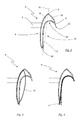
- Fig. 1 and Fig. 2 show a vertical wind turbine 1 with five rotor blades 2, which are fixed by radial struts 3 to a rotor 4 and are arranged parallel to a perpendicular axis of rotation 5 of the rotor 4.
- rotor blades 2 are provided, but at least one rotor blade 2 with the configuration explained below.
- the rotor blades 2 are symmetrical, that is arranged at equal angular intervals to each other.
- the rotor blades 2 have a profile cross-section 6 described in more detail below.
- the profile cross-section 6 causes incoming air to generate forces on the rotor blades 2 whose vector sum generates a resultant torque about the rotation axis 5, so that the rotor 4 is driven in a direction of movement 7.
- all rotor blades 2 are designed with the same profile cross-section 6.
- some of the rotor blades arranged on the circumference of the rotor 4 are designed with the profile cross-section 6 according to the invention described below.
- the rotor blades 2 according to the invention are advantageously arranged at equal intervals on the circumference of the rotor 4, wherein between the rotor blades 2 according to the invention such rotor blades are arranged with other profile cross-sections.
- one of the profile pages as buoyancy profile page 9 with a wing profile in the manner of a buoyancy rotor and the other of the profile pages as a resistance profile page 10 with an opposite Movement direction 7 of the rotor blade 2 open blade 11 formed in the manner of a resistance rotor.
- the blade 11 delimits a circular blade channel 12, which extends axially over the length of the rotor blade 2.
- the rotor blade 2 generates at standstill or low speeds of the vertical wind turbine 1 on the resistance profile side 10 a strong torque when the blade 11 captures the oncoming wind. With higher wind speeds, the effect of the buoyancy profile side 9 of the rotor blade 2 is increasing.
- the vertical wind turbine 1 behaves increasingly like a lift rotor and accelerates with the increase in rotational speeds, so that high performance coefficients are achieved.
- a buoyancy profile side 9 and a resistance profile side 10 on both sides of the profile nose 8, that is lying opposite and separated by the profile nose 8 is in Fig. 4 an exemplary profile cross-section of a pure lift rotor 13 (NACA profile) in registration with the profile cross-section 6 according to the invention (FIG. Fig. 3 ).
- the profile of the lift rotor 13 is not part of the rotor blade according to the invention, but only for the purpose of illustrating the formation of the buoyancy profile side 9 of the profile cross-section 6 according to the invention.
- the buoyancy profile side 9 has a convexly curved course, which corresponds to one of the profile sides of the buoyancy runner 13.
- a resistance profile side 10 is provided in the rotor blade according to the invention.
- FIG Fig. 5 The profile cross section 6 of the rotor blade 2 according to the invention with a resistance profile side 10 is shown in FIG Fig. 5 represented at the same time with a profile cross section of a pure resistance rotor 14.
- the resistance rotor 14 is conventionally made as shown from a sheet whose free end is bent into a blade.
- the representation according to Fig. 5 illustrates the formation of the resistance profile side 10 in the profile cross-section 6 of the rotor blade 2 according to the invention with a contact characteristic of a conventional resistance rotor fourteenth
- the profile cross-section 6 of the rotor blade 2 is a closed hollow chamber profile, the buoyancy profile side 9 and the resistance profile side 10 being brought together at the profile nose 8 and a profile trailing edge 15.
- the closed hollow chamber profile has a low weight by the inclusion of a hollow chamber 16 through a continuous wall with low wall thicknesses and yet has a high rigidity, in particular a high torsional stiffness, so that the rotor blade 2 the mechanical loads occurring at high speeds despite low weight withstand. For torsional stiffness of the rotor blade 2 also contributes the profile nose 8 at.
- hollow chamber profile webs are provided in an embodiment, not shown, which connect and support substantially transversely to the direction of movement 7, the opposite wall portions of the hollow chamber profile.
- Such a profile cross section can be produced in the extrusion process.
- the rotor blade 2 with a hollow chamber profile is composed of several shell parts, which are easy to manufacture in each case.
- the rotor blade is advantageously made of aluminum sheet or other metal sheets, in particular light metals.
- the rotor blade is a component of fiber-reinforced plastic, in particular glass fiber reinforced plastic (GRP) or carbon fiber reinforced plastic (GRP), or consists of several fiber-reinforced plastic components.
- a maximum resistance surface with a corresponding width of the blade 11 and the blade channel 12 is formed by a subsequent to the blade 11 base wall 17 of the resistance profile side 12 is on the same side of a chord 18 as the buoyancy profile page 9.
- the chord profile 18th is determined by the profile nose 8 and the profile trailing edge 15.
- the position of the base wall 17 on one of the lift profile side facing side of the chord 18 is particularly advantageous in the design of the rotor blade 2 as a hollow chamber profile, since the hollow chamber profile with low weight large profile depths can be selected while the position of the base side 17 as wide as possible blade channel 12th limited.
- the profile cross-section 6 is formed in a convex surface portion 19 between the profile nose 8 and an outer blade edge 20 of the blade 11 as a buoyancy profile.
- the convex surface portion 19 cooperates aerodynamically with the lift profile side 9 and contributes to the acceleration of the rotor blade 2 at.
- the aerodynamically favorable convex course of the surface immediately adjacent to the blade edge 20 further reduces turbulence due to the blade edge 20 and increases the efficiency of the rotor blade second
- Fig.1 and Fig. 2 is the buoyancy profile side 9 of the axis of rotation 5 of the vertical wind turbine 1 facing.
- alternating sequences of rotor blades with the axis of rotation 5 facing buoyancy profile sides 9 and such rotor blades are provided, in which the buoyancy profile side with respect to the axis of rotation 5 is outside.
- the buoyancy profile sides of all rotor blades are arranged on the profile side of the profile cross-section 6 lying outside on the axis of rotation 5.
- the rotor blade 2 Due to the design of the rotor blade 2 as a combination of resistance rotor and buoyancy rotor can be achieved with the rotor blade according to the invention initially a significantly lower startup speed of the vertical wind turbine 1, as is possible with buoyancy runners. Furthermore, the advantages of fast-running wing profiles are used, especially at higher speeds, which are not achievable with pure resistance rotors.
- the inventive combination of resistance rotor and buoyancy rotor is realized on individual rotor blades 2, so that the advantages of this combination with low material costs and thus low total weight of the vertical wind turbine 1 are used in favor of an improved performance map of the vertical wind turbine 1.
- the buoyancy profile side 9 is impinged independently of the resistance profile side 10 so that dynamic buoyancy forces act on the rotor blade, since the resistance profile side 10 lies on the other side of the profile nose 8 as the buoyancy profile side 9.
- the resistance profile side 10 can therefore hinder the free flow of the buoyancy profile side 9 by the wind or the more influent with increasing speed wind in no rotor position, so that the vertical wind turbine 1 can accelerate.
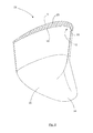
- a fin 22 is arranged in each case, which extends in the direction of the resistance profile side 10 bent.
- the fin 22 has on its side facing the rotor blade 2 base 23 to the profile cross-section of the rotor blade 2 and is tapered to its opposite, free end to a tongue 24.
- the fin 22 acts aerodynamically similar to a tail in aircraft and increases the coefficient of performance of the vertical wind turbine 1, since less drag resistance and turbulence arise at the trailing edges of the rotor blade 2. Further, the noise 22 of the vertical wind turbine 1 is reduced by the fins 22.
- the fin 22 also closes the hollow chamber 16 of the closed profile cross-section 6, whereby the efficiency of the rotor blade 2 is increased.
- the surface of the fin 22 is spherically formed on the side which adjoins the buoyancy profile side 9 of the rotor blade 2 and thereby promotes the buoyancy-generating properties of the rotor blade 2.
- the fin 22 continues one of the buoyancy profile side 9 associated section of the profile cross section 6 and covers the resistance profile side 10 to form an opening to the blade channel 12.
- the tongue 24 forms a chute 25 through the dirt, rainwater or a snow column discharged from the blade channel 12 become.
- the fin 22 is a component which can be inserted into the hollow chamber 16 of the rotor blade 2.
- the fin 22 may be made with a paragraph, so that the surface of the fin 22 is aligned with the surface of the rotor blade 2 after insertion into the hollow chamber 16.
- the fin 22 is butt-mounted to the free end of the rotor blade 2.
- the Fin 22 made of a glass or carbon fiber reinforced plastic. It may be partially formed as a hollow chamber profile, whereby further weight and material of the vertical wind turbine 1 can be saved.
- the fin 22 is formed integrally with the rotor blade 2 in a further advantageous embodiment.
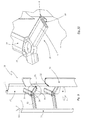
- Fig. 9 shows a further embodiment of a vertical wind turbine 30, which in contrast to the embodiment according to Fig. 1 and Fig. 2 has three vertically arranged rotor blades 31.
- the rotor blades 31 are each similar to a profile cross section 32 of the above with reference to FIG. 3 to FIG. 5 designed profile configuration designed.
- the profile cross section 31 of each rotor blade 31 in this case has a profile nose 8 arranged in advance in the direction of movement 7 and two profile sides on both sides of the profile nose 8.
- one of the profile sides is designed as a lift profile side 9 with an airfoil profile in the manner of a lift rotor and the other of the profile sides as a resistance profile side 10 with a counter to the direction of movement 7 of the rotor blade 2 open blade 11 in the manner of a resistance rotor.
- the rotor blades 31 are configured as solid profiles.
- the rotor blades 31 are advantageously components made of fiber-reinforced plastic, in particular glass fiber reinforced plastic (GRP) or carbon fiber reinforced plastic (GRP).
- GRP glass fiber reinforced plastic
- GRP carbon fiber reinforced plastic
- the rotor blades 31 of the vertical wind turbine according to Fig. 9 as hollow chamber profiles according to the Fig. 1 and Fig. 2 configured configuration configured.
- the free ends of the rotor blades 31 are in an embodiment, not shown, with fins 22 (FIG. Fig. 6 ) according to the embodiment according to Fig. 1 and Fig. 2 Mistake.
- the fins 22 are attached to the free ends of the rotor blade 31 with solid profile.
- the fins 22 are advantageously designed as an insertion part.
- the rotor blades 31 are held on radial struts 33 which hold the rotor blades 31 at the intended radial distance from the axis of rotation of the rotor.
- the struts 33 each hold at their radially outer ends a rotor blade and are mounted at their inner ends to a rotor ring 34 which rotates in the installation position of the rotor about the axis of rotation.
- the radial struts 33 are formed with a profile cross section 35 similar to the profile cross section 32 of the rotor blades 31.
- a similar profile cross section 35 is understood to mean that the profile cross section 35 of the radial struts 33 has the characteristic of the profile configuration according to the invention with a resistance profile side and a lift profile side.
- Each strut 33 comprises a profile nose 8 arranged in advance in the direction of movement 7 and two profile sides opposite the profile nose 8.
- One of the profile sides is designed as a lift profile side 9 with an airfoil profile in the manner of a lift rotor and the other of the profile sides as a resistance profile side 10.
Landscapes
- Engineering & Computer Science (AREA)
- Life Sciences & Earth Sciences (AREA)
- Sustainable Development (AREA)
- Sustainable Energy (AREA)
- Chemical & Material Sciences (AREA)
- Combustion & Propulsion (AREA)
- Mechanical Engineering (AREA)
- General Engineering & Computer Science (AREA)
- Physics & Mathematics (AREA)
- Fluid Mechanics (AREA)
- Wind Motors (AREA)
Applications Claiming Priority (1)
| Application Number | Priority Date | Filing Date | Title |
|---|---|---|---|
| DE102011118844A DE102011118844B3 (de) | 2011-11-18 | 2011-11-18 | Vertikalwindturbine und Rotorblatt hierfür |
Publications (2)
| Publication Number | Publication Date |
|---|---|
| EP2594784A2 true EP2594784A2 (fr) | 2013-05-22 |
| EP2594784A3 EP2594784A3 (fr) | 2014-08-06 |
Family
ID=47221170
Family Applications (1)
| Application Number | Title | Priority Date | Filing Date |
|---|---|---|---|
| EP12192863.4A Withdrawn EP2594784A3 (fr) | 2011-11-18 | 2012-11-15 | Éolienne verticale et pale de rotor pour celle-ci |
Country Status (2)
| Country | Link |
|---|---|
| EP (1) | EP2594784A3 (fr) |
| DE (1) | DE102011118844B3 (fr) |
Cited By (7)
| Publication number | Priority date | Publication date | Assignee | Title |
|---|---|---|---|---|
| CN105765215A (zh) * | 2013-10-18 | 2016-07-13 | 山泽利充 | 风力发电装置 |
| WO2018193998A1 (fr) * | 2017-04-18 | 2018-10-25 | Ntn株式会社 | Éolienne à arbre vertical et dispositif de production d'énergie éolienne |
| JP2018178917A (ja) * | 2017-04-18 | 2018-11-15 | Ntn株式会社 | 垂直軸風車および風力発電装置 |
| US10378510B2 (en) | 2014-04-28 | 2019-08-13 | Alexander Margolis | Vertical axis wind turbine with self-orientating blades |
| US10408190B2 (en) | 2016-10-07 | 2019-09-10 | Robert B. Deioma | Wind turbine with open back blade |
| US11143163B2 (en) | 2016-03-08 | 2021-10-12 | Semtive Inc. | Vertical axis wind turbine |
| US11664663B2 (en) | 2018-09-12 | 2023-05-30 | Semtive Inc. | Micro inverter and controller |
Families Citing this family (6)
| Publication number | Priority date | Publication date | Assignee | Title |
|---|---|---|---|---|
| CN103321833B (zh) * | 2013-05-24 | 2015-12-02 | 张远林 | 一种用于h型垂直轴风力发电机的叶片结构 |
| USD713789S1 (en) | 2013-10-25 | 2014-09-23 | Abundant Energy, LLC | Vertical axis wind turbine apparatus |
| EP2886855A1 (fr) * | 2013-12-17 | 2015-06-24 | Perpend AB | Éolienne à axe vertical, pâle métallique segmentéee et méthode de fabrication |
| DE102014108177A1 (de) | 2014-06-11 | 2015-12-31 | Marinko Bakula | Vertikalrotor und diesen umfassende Wind- oder Wasserturbine |
| DE202015003173U1 (de) | 2015-04-30 | 2015-06-17 | Michael Pionke | Rotorblatt für einen Rotor für Windkraftanlagen |
| WO2019165490A1 (fr) | 2018-02-28 | 2019-09-06 | Axis Energy Group Pty Ltd | Turbine à axe vertical |
Citations (4)
| Publication number | Priority date | Publication date | Assignee | Title |
|---|---|---|---|---|
| DE4120908C2 (de) | 1991-06-25 | 1998-04-23 | Raban Von Canstein Carl Magnus | Strömungsrezeptor |
| DE202009007926U1 (de) | 2009-06-05 | 2009-08-20 | Debus, Martin | Kombiwindkraftanlage |
| DE102009013666A1 (de) | 2009-03-25 | 2010-10-07 | BBA Konstruktionsbüro und Vertrieb Bau- und Bergbauausrüstung GbR (vertretungsberechtigter Gesellschafter: Simon Franz, 08280 Aue) | Windrad mit vertikaler Achse |
| DE202010011597U1 (de) | 2010-08-18 | 2011-01-05 | Pacardo, Stephan | Rotorflügel für Vertikalwindkraftanlagen |
Family Cites Families (5)
| Publication number | Priority date | Publication date | Assignee | Title |
|---|---|---|---|---|
| DE3626917A1 (de) * | 1986-06-03 | 1987-12-10 | Erich Herter | Windturbine |
| DE10105570B4 (de) * | 2001-02-06 | 2005-03-24 | Althaus, Wolfgang, Dr.-Ing. | Windkraftmaschine |
| US20070134094A1 (en) * | 2005-12-08 | 2007-06-14 | Stephen Gregory | Rotor apparatus and turbine system incorporating same |
| DE102008018729A1 (de) * | 2008-04-14 | 2009-10-15 | GÜNTHER, Eggert | Segel-Vertikalachsrotor |
| DE202008014838U1 (de) * | 2008-11-07 | 2009-01-15 | Andrich, Detlef, Dr.-Ing. | Freitragender Vertikalachs-H-Durchström-Auftriebs-Rotor |
-
2011
- 2011-11-18 DE DE102011118844A patent/DE102011118844B3/de not_active Expired - Fee Related
-
2012
- 2012-11-15 EP EP12192863.4A patent/EP2594784A3/fr not_active Withdrawn
Patent Citations (4)
| Publication number | Priority date | Publication date | Assignee | Title |
|---|---|---|---|---|
| DE4120908C2 (de) | 1991-06-25 | 1998-04-23 | Raban Von Canstein Carl Magnus | Strömungsrezeptor |
| DE102009013666A1 (de) | 2009-03-25 | 2010-10-07 | BBA Konstruktionsbüro und Vertrieb Bau- und Bergbauausrüstung GbR (vertretungsberechtigter Gesellschafter: Simon Franz, 08280 Aue) | Windrad mit vertikaler Achse |
| DE202009007926U1 (de) | 2009-06-05 | 2009-08-20 | Debus, Martin | Kombiwindkraftanlage |
| DE202010011597U1 (de) | 2010-08-18 | 2011-01-05 | Pacardo, Stephan | Rotorflügel für Vertikalwindkraftanlagen |
Cited By (9)
| Publication number | Priority date | Publication date | Assignee | Title |
|---|---|---|---|---|
| CN105765215A (zh) * | 2013-10-18 | 2016-07-13 | 山泽利充 | 风力发电装置 |
| EP3059443A4 (fr) * | 2013-10-18 | 2017-06-28 | Toshimitsu Yamazawa | Dispositif de génération d'énergie éolienne |
| CN105765215B (zh) * | 2013-10-18 | 2021-09-03 | 山泽利充 | 风力发电装置 |
| US10378510B2 (en) | 2014-04-28 | 2019-08-13 | Alexander Margolis | Vertical axis wind turbine with self-orientating blades |
| US11143163B2 (en) | 2016-03-08 | 2021-10-12 | Semtive Inc. | Vertical axis wind turbine |
| US10408190B2 (en) | 2016-10-07 | 2019-09-10 | Robert B. Deioma | Wind turbine with open back blade |
| WO2018193998A1 (fr) * | 2017-04-18 | 2018-10-25 | Ntn株式会社 | Éolienne à arbre vertical et dispositif de production d'énergie éolienne |
| JP2018178917A (ja) * | 2017-04-18 | 2018-11-15 | Ntn株式会社 | 垂直軸風車および風力発電装置 |
| US11664663B2 (en) | 2018-09-12 | 2023-05-30 | Semtive Inc. | Micro inverter and controller |
Also Published As
| Publication number | Publication date |
|---|---|
| EP2594784A3 (fr) | 2014-08-06 |
| DE102011118844B3 (de) | 2013-04-18 |
Similar Documents
| Publication | Publication Date | Title |
|---|---|---|
| DE102011118844B3 (de) | Vertikalwindturbine und Rotorblatt hierfür | |
| EP1177381B1 (fr) | Centrale eolienne a rotor vertical | |
| DE60125172T2 (de) | Rotorblatt für eine windkraftanlage | |
| DE10347802B3 (de) | Rotorblatt für eine Windkraftanlage | |
| DE19957141B4 (de) | Windkraftanlage mit Vertikalrotor und Frontalanströmung | |
| EP2145102A2 (fr) | Bras de support destiné aux pales de turbines éoliennes présentant un axe de rotation vertical | |
| EP2004990A1 (fr) | Pale de rotor d'un dispositif d'énergie éolienne | |
| DE202007008125U1 (de) | Vertikal-Windkraftanlage sowie Rotorblatt | |
| DE202013101943U1 (de) | Vorrichtung zur Verringerung des Antriebsleistungsbedarfs eines Wasserfahrzeuges | |
| DE202016101461U1 (de) | Rotorblatt für Windenergieanlagen mit horizontaler Drehachse sowieWindenergieanlage mit selbigem | |
| EP2568166B1 (fr) | Pale de rotor d'éolienne dotée d'un rebord arrière à profil épais | |
| DE102008044807A1 (de) | Strömungskonverter, insbesondere Windkraftkonverter | |
| DE29920899U1 (de) | Windkraftanlage mit Vertikalrotor und Frontalanströmung | |
| EP3399183B1 (fr) | Pale de rotor d'une éolienne | |
| DE202012013307U1 (de) | Windkraftanlage und Turbinenlaufrad hierfür | |
| DE202008005724U1 (de) | Axial durchströmte Windturbine | |
| DE10340112A1 (de) | Windkraftanlage | |
| EP3844384A1 (fr) | Pale de rotor, éolienne et procédé d'optimisation d'une éolienne | |
| EP2927476A1 (fr) | Rotor et turbine à entraînement fluidique dotée de rotor | |
| DE102010016086A1 (de) | Rotorblatt für H-Rotor | |
| CH700422B1 (de) | Axial durchströmte Windturbine. | |
| DE10239498A1 (de) | Windkraftmaschine | |
| DE102008051297B3 (de) | Rotorblatt einer Windkraftanlage | |
| DE3715265A1 (de) | Windturbine | |
| AT500816B1 (de) | Motorgetriebener propeller für einen flugkörper |
Legal Events
| Date | Code | Title | Description |
|---|---|---|---|
| PUAI | Public reference made under article 153(3) epc to a published international application that has entered the european phase |
Free format text: ORIGINAL CODE: 0009012 |
|
| AK | Designated contracting states |
Kind code of ref document: A2 Designated state(s): AL AT BE BG CH CY CZ DE DK EE ES FI FR GB GR HR HU IE IS IT LI LT LU LV MC MK MT NL NO PL PT RO RS SE SI SK SM TR |
|
| AX | Request for extension of the european patent |
Extension state: BA ME |
|
| PUAL | Search report despatched |
Free format text: ORIGINAL CODE: 0009013 |
|
| AK | Designated contracting states |
Kind code of ref document: A3 Designated state(s): AL AT BE BG CH CY CZ DE DK EE ES FI FR GB GR HR HU IE IS IT LI LT LU LV MC MK MT NL NO PL PT RO RS SE SI SK SM TR |
|
| AX | Request for extension of the european patent |
Extension state: BA ME |
|
| RIC1 | Information provided on ipc code assigned before grant |
Ipc: F03D 3/06 20060101ALI20140703BHEP Ipc: F03D 3/00 20060101AFI20140703BHEP |
|
| STAA | Information on the status of an ep patent application or granted ep patent |
Free format text: STATUS: THE APPLICATION IS DEEMED TO BE WITHDRAWN |
|
| 18D | Application deemed to be withdrawn |
Effective date: 20150207 |