EP2594718A2 - Vorrichtung zum Fixieren eines Baukörpers in einer Gebäudeöffnung - Google Patents
Vorrichtung zum Fixieren eines Baukörpers in einer Gebäudeöffnung Download PDFInfo
- Publication number
- EP2594718A2 EP2594718A2 EP12191905.4A EP12191905A EP2594718A2 EP 2594718 A2 EP2594718 A2 EP 2594718A2 EP 12191905 A EP12191905 A EP 12191905A EP 2594718 A2 EP2594718 A2 EP 2594718A2
- Authority
- EP
- European Patent Office
- Prior art keywords
- leg
- openings
- angle part
- support element
- fixing
- Prior art date
- Legal status (The legal status is an assumption and is not a legal conclusion. Google has not performed a legal analysis and makes no representation as to the accuracy of the status listed.)
- Granted
Links
Images
Classifications
-
- E—FIXED CONSTRUCTIONS
- E06—DOORS, WINDOWS, SHUTTERS, OR ROLLER BLINDS IN GENERAL; LADDERS
- E06B—FIXED OR MOVABLE CLOSURES FOR OPENINGS IN BUILDINGS, VEHICLES, FENCES OR LIKE ENCLOSURES IN GENERAL, e.g. DOORS, WINDOWS, BLINDS, GATES
- E06B1/00—Border constructions of openings in walls, floors, or ceilings; Frames to be rigidly mounted in such openings
- E06B1/56—Fastening frames to the border of openings or to similar contiguous frames
- E06B1/60—Fastening frames to the border of openings or to similar contiguous frames by mechanical means, e.g. anchoring means
- E06B1/6015—Anchoring means
Definitions
- the invention relates to a device for fixing a structure, in particular a window frame, in a building opening with a number of openings having support member for supporting the structure, wherein the support element is fixable via fastening means on an edge of the building opening.
- a device for fixing a building in a building opening in which a profiled rail-shaped support member is provided, which is connectable in a mounting position on one side with a masonry (edge of the building opening) and on the other side with the building (window frame).
- the support member has a slot, so that a trained as a threaded rod fixing in the Depth and height adjustable and can be fixed by screwing.
- the fixing is firmly connected to the window frame before taking the mounting position.
- Object of the present invention is to develop a device for fixing a building in a building opening such that an adjustment or adjustment of the building in a mounting position as simple as possible and without the use of a threaded rod is made possible.
- the invention in connection with the preamble of claim 1, characterized in that the building is connected via an angle part with the support member in a mounting position, wherein a first leg of the angle part a plurality of openings for fixing to the building and a second leg of the angle part having a plurality of openings for fixing to the support element.
- the particular advantage of the invention is that after alignment of the structure, for example, in height and in depth by means of flat support elements only an angle part with a preferably elongated support member needs to work together.
- the angle part is easy to produce and has only two legs, which are each provided with a number of openings.
- the openings serve to engage fastening means preferably designed as fastening screws, which fixation between the angle part and the structure allow on the one hand and the angle part and the support element on the other. Due to the majority of the openings provided on the legs, a suitable opening can optionally be selected for fastening the angle part.
- the invention allows for installation of the trained as a window structure in a building opening that no unwanted cold bridge between a bottom of the window frame and an underlying insulating material due to otherwise existing fasteners.
- Between the window frame and the insulating material extends only the support element, while the angle provided for fastening angle member is arranged on a building inner side of the window frame. Since no fasteners (screw) must be mounted below the window, a free cutting of the arranged below the window insulation is not required.
- the two legs of the angle part are arranged at right angles to each other, so that a defined contact surface of the structural body associated leg is ensured on a side surface of the same.
- the two legs of the angle part are not the same length, so that depending on the current installation conditions a secure attachment is possible.
- the positioning of the structure is carried out on the support element already attached to the edge of the building opening by means of additional installation aids, which are removed again after fixing the angle part.
- the assembly aids are formed as thin platelets (flat support elements), which are anyway used when setting up a window at the construction site or are available.
- the support member may have a commercially available profile-shaped configuration.
- a device for fixing a building in a building opening is preferably used for fixing a window frame 1 in the building opening.
- a support element 3 designed as a U-shaped profile element and an angle part 4 are essentially provided.
- the rail 3 in a building inside first half 5 via openings (round holes 6, slots 6 ') with a masonry 7 is firmly connected.
- one or more fastening screws, not shown, are inserted with their shank through the matching openings 6, 6 'of the longitudinal axis and screwed to the masonry 7 via further retaining means.
- a first leg 8 of the angle part 4 has a plurality of openings 9, which are preferably arranged distributed evenly over the surface of the first leg 8. These openings 9 have a diameter which is smaller than the diameter of the openings 6, 6 'of the rail 3.
- two openings 9 can be selected, which are fixedly connected via fastening screws 10 as fastening means with the rail 3.
- self-tapping screws 10 are inserted into the corresponding opening 9 and then allow by self-tapping turning a firm connection between the bracket 4 and the rail 3.
- a second newly formed leg 11 of the angle part 4 extends at right angles to the first leg 8 and also has a plurality of preferably equally distributed openings 12.
- the diameters of the openings 9, 12 are preferably the same size.
- the second leg 11 is fixedly connected by appropriate fastening screws 10 with the preferably made of a plastic material window frame 1.
- the angle part 4 is arranged on a building interior side above the rail 3, no unwanted cold bridge is formed in an area between the window frame 1 and a lower lying in the vertical direction insulating material 13. Between the insulating material 13 and the window frame 1, only the profile rail 3 runs.
- the support element 3 may also be formed plate-shaped without profiling.
- a length 11 of the first leg 8 is greater than a length 12 of the second leg 11.
- the angle part 4 can be applied twisted in a simple manner, so that the long first leg 8 on the window frame 1 and the short second leg 11 come to the rail 3 to the plant.
- the rail 3 is attached to the masonry 7. Subsequently, the window frame 1 is placed on the support element 3 and adjusted in height by means of a corresponding number of mounting aids 14 formed as mounting aid, which are placed on a building exterior side second half 15 of the rail 3, in height. Subsequently, the angle part 4 is fixed by means of fastening screws 10 on the rail 3 and on the window frame 1. The support plates 14 can now be removed because the window frame 1 is in the intended fixed mounting position.
- the rail 3 and the angle part 4 are preferably made of a metal material.
- the first half 5 and the second half 15 of the rail 3 are arranged separated by a transverse center plane Q.
- the openings 6, 6 ' are preferably distributed in a longitudinal center plane M of the rail.
Landscapes
- Engineering & Computer Science (AREA)
- Mechanical Engineering (AREA)
- Civil Engineering (AREA)
- Structural Engineering (AREA)
- Door And Window Frames Mounted To Openings (AREA)
Abstract
Description
- Die Erfindung betrifft eine Vorrichtung zum Fixieren eines Baukörpers, insbesondere eines Fensterrahmens, in einer Gebäudeöffnung mit einem eine Anzahl von Öffnungen aufweisenden Abstützelement zum Abstützen des Baukörpers, wobei das Abstützelement über Befestigungsmittel an einem Rand der Gebäudeöffnung festlegbar ist.
- Aus der
EP 2 309 089 A2 ist eine Vorrichtung zum Fixieren eines Baukörpers in einer Gebäudeöffnung bekannt, bei der ein profilschienenförmiges Abstützelement vorgesehen ist, das in einer Montageposition auf der einen Seite mit einem Mauerwerk (Rand der Gebäudeöffnung) und auf der anderen Seite mit dem Baukörper (Fensterrahmen) verbindbar ist. Zur Justierung des Fensterrahmens in der Tiefe und in der Höhe weist das Abstützelement ein Langloch auf, so dass ein als Gewindestange ausgebildetes Fixierelement in der Tiefe und in der Höhe verstellbar und durch Verschraubung festlegbar ist. Das Fixierelement ist vor Einnahme der Montageposition fest mit dem Fensterrahmen verbunden. - Aufgabe der vorliegenden Erfindung ist es, eine Vorrichtung zum Fixieren eines Baukörpers in einer Gebäudeöffnung derart weiterzubilden, dass eine Justierung bzw. Einstellung des Baukörpers in einer Montageposition möglichst einfach und ohne Einsatz einer Gewindestange ermöglicht wird.
- Zur Lösung der Aufgabe ist die Erfindung in Verbindung mit dem Oberbegriff des Patentanspruchs 1 dadurch gekennzeichnet, dass der Baukörper über ein Winkelteil mit dem Abstützelement in einer Montageposition verbindbar ist, wobei ein erster Schenkel des Winkelteils eine Mehrzahl von Öffnungen zur Fixierung an dem Baukörper und ein zweiter Schenkel des Winkelteils eine Mehrzahl von Öffnungen zur Fixierung an dem Abstützelement aufweisen.
- Der besondere Vorteil der Erfindung besteht darin, dass nach Ausrichtung des Baukörpers beispielsweise in der Höhe und in der Tiefe mittels flachen Stützelementen lediglich ein Winkelteil mit einem vorzugsweise langgestreckten Abstützelement zusammenwirken braucht. Das Winkelteil ist einfach herstellbar und weist lediglich zwei Schenkel auf, die jeweils mit einer Anzahl von Öffnungen versehen sind. Die Öffnungen dienen zum Eingreifen von vorzugsweise als Befestigungsschrauben ausgebildeten Befestigungsmitteln, die eine Fixierung zwischen dem Winkelteil und dem Baukörper einerseits und dem Winkelteil und dem Abstützelement andererseits ermöglichen. Aufgrund der Mehrzahl der an den Schenkeln vorgesehenen Öffnungen kann zur Befestigung des Winkelteils wahlweise eine passende Öffnung ausgesucht werden. Vorteilhaft ermöglicht die Erfindung bei Einbau des als ein Fenster ausgebildeten Baukörpers in eine Gebäudeöffnung, dass keine unerwünschte Kältebrücke zwischen einer Unterseite des Fensterrahmens und einem darunter liegenden Dämmmaterial aufgrund von ansonsten vorhandenen Befestigungsmitteln entsteht. Zwischen dem Fensterrahmen und dem Dämmmaterial verläuft lediglich das Abstützelement, währenddessen das zur Befestigung vorgesehene Winkelteil auf einer gebäudeinneren Seite des Fensterrahmens angeordnet ist. Da keine Befestigungsmittel (Verschraubung) unterhalb des Fensters angebracht werden müssen, ist ein Freischneiden des unterhalb des Fensters angeordneten Dämmmaterials nicht erforderlich.
- Nach einer Weiterbildung der Erfindung sind die beiden Schenkel des Winkelteils rechtwinklig zueinander angeordnet, so dass eine definierte Anlagefläche des dem Baukörper zugeordneten Schenkels an einer Seitenfläche desselben gewährleistet ist.
- Nach einer Weiterbildung der Erfindung sind die beiden Schenkel des Winkelteils nicht gleich lang ausgebildet, so dass in Abhängigkeit von den aktuellen Montagebedingungen eine sichere Befestigung ermöglicht wird.
- Nach einer Weiterbildung der Erfindung erfolgt die Positionierung des Baukörpers an dem bereits am Rand der Gebäudeöffnung befestigten Abstützelementes mittels zusätzlicher Montagehilfsmittel, die nach Fixieren des Winkelteils wieder entnommen werden. Vorzugsweise sind die Montagehilfsmittel als dünne Plättchen (flache Stützelemente) ausgebildet, die ohnehin beim Einrichten eines Fensters an der Baustelle eingesetzt werden bzw. zur Verfügung stehen. Auch das Abstützelement kann eine handelsüblich profilförmige Ausgestaltung aufweisen.
- Weitere Vorteile der Erfindung ergeben sich aus den weiteren Unteransprüchen.
- Ein Ausführungsbeispiel der Erfindung wird nachfolgend anhand der Zeichnungen näher erläutert.
- Es zeigen:
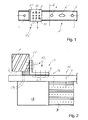
- Figur 1
- einen Vertikalschnitt durch eine erfindungsgemäße Vorrichtung in einer Montageposition zur Fixierung eines Fensters in einer Gebäudeöffnung und
- Figur 2
- eine Draufsicht auf ein Winkelteil, das über Befestigungsmittel an einem Abstützelement befestigt ist.
- Eine Vorrichtung zum Fixieren eines Baukörpers in einer Gebäudeöffnung dient vorzugsweise zum Fixieren eines Fensterrahmens 1 in der Gebäudeöffnung. Zur Fixierung insbesondere einer Unterseite 2 des Fensterrahmens 1 ist im Wesentlichen ein als U-förmiges Profilelement ausgebildetes Abstützelement 3 sowie ein Winkelteil 4 vorgesehen.
- In der Montageposition des Fensterrahmens 1 ist die Profilschiene 3 in einer gebäudeinnenseitigen ersten Hälfte 5 über Öffnungen (Rundlöcher 6, Langlöcher 6') mit einem Mauerwerk 7 fest verbunden. Hierzu werden eine oder mehrere nicht dargestellte Befestigungsschrauben mit ihrem Schaft durch die passenden Öffnungen 6, 6' der Längsachse eingesetzt und mit dem Mauerwerk 7 über weitere Haltemittel verschraubt.
- Ein erster Schenkel 8 des Winkelteils 4 weist eine Mehrzahl von Öffnungen 9 auf, die vorzugsweise gleich verteilt über die Fläche des ersten Schenkels 8 angeordnet sind. Diese Öffnungen 9 weisen einen Durchmesser auf, der kleiner ist als der Durchmesser der Öffnungen 6, 6' der Profilschiene 3. In der Montageposition können beispielsweise zwei Öffnungen 9 ausgewählt werden, die über Befestigungsschrauben 10 als Befestigungsmittel fest mit der Profilschiene 3 verbindbar sind. Zu diesem Zweck werden selbstschneidende Befestigungsschrauben 10 in die entsprechende Öffnung 9 eingesetzt und ermöglichen dann durch selbstschneidendes Drehen eine feste Verbindung zwischen dem Winkelteil 4 und der Profilschiene 3 .
- Ein zweiter eben ausgebildeter Schenkel 11 des Winkelteils 4 erstreckt sich rechtwinklig zu dem ersten Schenkel 8 und weist ebenfalls eine Mehrzahl von vorzugsweise gleich verteilten Öffnungen 12 auf. Die Durchmesser der Öffnungen 9, 12 sind vorzugsweise gleich groß. In der Montageposition wird der zweite Schenkel 11 durch entsprechende Befestigungsschrauben 10 fest mit dem vorzugsweise aus einem Kunststoffmaterial bestehenden Fensterrahmen 1 verbunden.
- Entsprechende Bohrungen des Fensterrahmens 1, mit denen die Befestigungsschrauben 10 in Eingriff stehen, liegen bereits herstellerseitig vor.
- Dadurch, dass zur Befestigung des Fensterrahmens 1 das Winkelteil 4 auf einer gebäudeinneren Seite oberhalb der Profilschiene 3 angeordnet ist, entsteht keine unerwünschte Kältebrücke in einem Bereich zwischen dem Fensterrahmen 1 und einem in vertikaler Richtung darunter liegenden Dämmmaterial 13. Zwischen dem Dämmmaterial 13 und dem Fensterrahmen 1 verläuft lediglich die Profilschiene 3.
- Nach einer alternativen Ausführungsform der Erfindung kann das Abstützelement 3 auch plattenförmig ohne eine Profilierung ausgebildet sein.
- Im vorliegenden Ausführungsbeispiel ist eine Länge 11 der erste Schenkel 8 größer als eine Länge 12 des zweiten Schenkels 11. In Abhängigkeit von den Montagebedingungen kann das Winkelteil 4 auf einfache Weise verdreht angelegt werden, so dass der lange erste Schenkel 8 an dem Fensterrahmen 1 und der kurze zweite Schenkel 11 an der Profilschiene 3 zur Anlage kommen.
- Zur Montage des Fensterrahmens 1 wird die Profilschiene 3 an dem Mauerwerk 7 befestigt. Nachfolgend wird der Fensterrahmen 1 auf das Abstützelement 3 aufgelegt und in der Höhe mittels einer entsprechenden Anzahl von als Montagehilfsmittel ausgebildeten Stützplättchen 14, die auf eine gebäudeaußenseitige zweiten Hälfte 15 der Profilschiene 3 aufgelegt werden, in der Höhe eingestellt. Nachfolgend wird das Winkelteil 4 mittels Befestigungsschrauben 10 an der Profilschiene 3 und an dem Fensterrahmen 1 befestigt. Die Stützplättchen 14 können nun entfernt werden, da sich der Fensterrahmen 1 in der vorgesehenen festen Montageposition befindet. Die Profilschiene 3 und das Winkelteil 4 sind vorzugsweise aus einem Metallmaterial hergestellt.
- Die erste Hälfte 5 und die zweite Hälfte 15 der Profilschiene 3 sind durch eine Quermittelebene Q getrennt angeordnet. Die Öffnungen 6, 6' sind vorzugsweise in einer Längsmittelebene M der Profilschiene verteilt angeordnet.
Claims (10)
- Vorrichtung zum Fixieren eines Baukörpers, insbesondere eines Fensterrahmens (1), in einer Gebäudeöffnung mit einem eine Anzahl von Öffnungen (6, 12) aufweisenden Abstützelement (3) zum Abstützen des Baukörpers (1), wobei das Abstützelement über Befestigungsmittel (10) an einem Rand der Gebäudeöffnung festlegbar ist, dadurch gekennzeichnet, dass der Baukörper (1) über ein Winkelteil (4) mit dem Abstützelement (3) in einer Montageposition verbindbar ist, wobei ein erster Schenkel (8) des Winkelteils (4) eine Mehrzahl von Öffnungen (9) zur Fixierung an dem Baukörper (1) und ein zweiter Schenkel (11) des Winkelteils (4) eine Mehrzahl von Öffnungen (12) zur Fixierung an dem Abstützelement (3) aufweisen.
- Vorrichtung nach Anspruch 1, dadurch gekennzeichnet, dass der erste Schenkel (8) und der zweite Schenkel (11) des Winkelteils (4) rechtwinklig zueinander verlaufen.
- Vorrichtung nach Anspruch 1 oder 2, dadurch gekennzeichnet, dass die Öffnungen (9, 12) des ersten Schenkels (8) und des zweiten Schenkels (11) des Winkelteils (4) einen kleineren Durchmesser aufweisen als die Öffnungen (6, 6') des Abstützelementes (3).
- Vorrichtung nach einem der Ansprüche 1 bis 3, dadurch gekennzeichnet, dass die Öffnungen (9, 12) des ersten Schenkels (8) und des zweiten Schenkels (11) verteilt über den eben ausgebildeten ersten Schenkel (8) und den eben ausgebildeten zweiten Schenkel (11) angeordnet sind.
- Vorrichtung nach einem der Ansprüche 1 bis 4, dadurch gekennzeichnet, dass der von einem Scheitel des Winkelteils (4) abragende erste Schenkel (8) eine Länge (11) aufweist, die größer ist als eine Länge (12) des zweiten Schenkels (11).
- Vorrichtung nach einem der Ansprüche 1 bis 5, dadurch gekennzeichnet, dass eine zu einer mit einer Befestigungsschraube (10) zu versehene Öffnung (9, 12) des ersten Schenkels (8) und/oder des zweiten Schenkels (11) fluchtende Öffnung (6, 6') des Abstützelementes (3) und/oder des Baukörpers (1) durch Einschneiden der Befestigungsschraube (10) ausbildbar ist.
- Vorrichtung nach einem der Ansprüche 1 bis 6, dadurch gekennzeichnet, dass der Baukörper (1) mittels Montagehilfsmitteln (14) in der Montageposition positionierbar ist.
- Vorrichtung nach Anspruch 7, dadurch gekennzeichnet, dass als Montagehilfsmittel mehrere Stützplättchen (14) vorgesehen sind.
- Vorrichtung nach einem der Ansprüche 1 bis 8, dadurch gekennzeichnet, dass das Abstützelement (3) als eine U-förmige Profilschiene oder als eine ebene Profilplatte ausgebildet ist.
- Vorrichtung nach einem der Ansprüche 1 bis 9, dadurch gekennzeichnet, dass das Abstützelement (3) und das Winkelteil (4) aus einem Metallmaterial, vorzugsweise einem gleichen Metallmaterial bestehen.
Applications Claiming Priority (1)
| Application Number | Priority Date | Filing Date | Title |
|---|---|---|---|
| DE202011108043U DE202011108043U1 (de) | 2011-11-18 | 2011-11-18 | Vorrichtung zum Fixieren eines Baukörpers in einer Gebäudeöffnung |
Publications (3)
| Publication Number | Publication Date |
|---|---|
| EP2594718A2 true EP2594718A2 (de) | 2013-05-22 |
| EP2594718A3 EP2594718A3 (de) | 2016-06-15 |
| EP2594718B1 EP2594718B1 (de) | 2022-05-25 |
Family
ID=45595976
Family Applications (1)
| Application Number | Title | Priority Date | Filing Date |
|---|---|---|---|
| EP12191905.4A Active EP2594718B1 (de) | 2011-11-18 | 2012-11-09 | Vorrichtung zum Fixieren eines Baukörpers in einer Gebäudeöffnung |
Country Status (3)
| Country | Link |
|---|---|
| EP (1) | EP2594718B1 (de) |
| DE (1) | DE202011108043U1 (de) |
| PL (1) | PL2594718T3 (de) |
Families Citing this family (2)
| Publication number | Priority date | Publication date | Assignee | Title |
|---|---|---|---|---|
| DE202014100214U1 (de) * | 2014-01-20 | 2014-03-14 | Knelsen Gmbh | Vorrichtung zum Fixieren eines Baukörpers |
| EP3696361B8 (de) | 2019-02-15 | 2022-05-04 | SFS Group International AG | Vorrichtung zum abstützen von fenster- oder türelementen |
Citations (1)
| Publication number | Priority date | Publication date | Assignee | Title |
|---|---|---|---|---|
| EP2309089A2 (de) | 2009-10-06 | 2011-04-13 | Knelsen GmbH | Vorrichtung zum Fixieren eines Baukörpers in einer Gebäudeöffnung |
Family Cites Families (6)
| Publication number | Priority date | Publication date | Assignee | Title |
|---|---|---|---|---|
| US4642955A (en) * | 1986-03-28 | 1987-02-17 | Webb Manufacturing, Inc. | Molded window assembly and transom support therefor |
| EP0945577B2 (de) | 1998-03-23 | 2010-03-24 | SFS intec Holding AG | Verwendung einer Profilschiene zum Abstützen von Fenster- oder Türrahmen |
| DE20308879U1 (de) | 2003-06-05 | 2003-09-11 | Fabricius Fastener GmbH, 33100 Paderborn | Montagekonsole für Fenster o.dgl. |
| DE20311512U1 (de) | 2003-07-25 | 2004-11-25 | Sfs Intec Holding Ag | Konsole zum Abstützen und Befestigen von Fenster- oder Türrahmen an der Begrenzung einer Wandöffnung |
| DE202006005375U1 (de) | 2006-03-31 | 2006-06-14 | Knelsen, Waldemar | Vorrichtung zum Justieren eines Baukörpers |
| DE102006020228A1 (de) | 2006-04-27 | 2007-10-31 | Sylid Systemlogistik Und Industriedienstleistung Gmbh | Montagesystem für Fenster und dergleichen |
-
2011
- 2011-11-18 DE DE202011108043U patent/DE202011108043U1/de not_active Expired - Lifetime
-
2012
- 2012-11-09 EP EP12191905.4A patent/EP2594718B1/de active Active
- 2012-11-09 PL PL12191905.4T patent/PL2594718T3/pl unknown
Patent Citations (1)
| Publication number | Priority date | Publication date | Assignee | Title |
|---|---|---|---|---|
| EP2309089A2 (de) | 2009-10-06 | 2011-04-13 | Knelsen GmbH | Vorrichtung zum Fixieren eines Baukörpers in einer Gebäudeöffnung |
Also Published As
| Publication number | Publication date |
|---|---|
| DE202011108043U1 (de) | 2012-01-12 |
| EP2594718A3 (de) | 2016-06-15 |
| EP2594718B1 (de) | 2022-05-25 |
| PL2594718T3 (pl) | 2022-10-03 |
Similar Documents
| Publication | Publication Date | Title |
|---|---|---|
| EP2435768B1 (de) | Vorrichtung zur befestigung einer montageschiene an einem gewindeschaft | |
| EP1849952A2 (de) | Montagesystem für Fenster und dergleichen | |
| EP1245916A2 (de) | Befestigung eines Türblatts an einer Gerätetür | |
| DE102004005422B4 (de) | Montagekonsole für Fenster oder dergleichen | |
| EP2594718B1 (de) | Vorrichtung zum Fixieren eines Baukörpers in einer Gebäudeöffnung | |
| DE202010014944U1 (de) | Justiersystem | |
| EP0447936B1 (de) | Vorrichtung zur Befestigung von Installationselementen | |
| EP2476843B1 (de) | Befestigungselement für die stirnseitige Befestigung einer Führungsschiene | |
| DE202010006771U1 (de) | Vorrichtung zur Befestigung von Bauteilen | |
| CH702591A2 (de) | Vorrichtung zur Montage von verschraubbaren Rohrschellen. | |
| EP2386700A1 (de) | Vorrichtung zum Halten einer Fassadenkassette | |
| DE202007013500U1 (de) | Verbinder sowie Anordnung von zwei mit einem solchen Verbinder verbundenen Gegenständen | |
| EP2700766B1 (de) | Fassadenbefestigungsvorrichtung | |
| EP2708679A2 (de) | Montagehilfsvorrichtung zur Montage einer Türzarge | |
| DE102014217781A1 (de) | Vorrichtung zum Befestigen eines Verkleidungselements | |
| DE10304361A1 (de) | Halter für plattenförmige Bauteile | |
| AT514593B1 (de) | Duschabtrennung | |
| EP2107173A2 (de) | Schlitzrinne mit Höhenverstellung | |
| EP1582802A1 (de) | Halterungsvorrichtung für einen Flachbildschirm | |
| DE102013004915A1 (de) | Vorrichtung zur Befestigung von Zaunmatten an Zaunpfählen | |
| DE202007019221U1 (de) | Vorrichtung zur Befestigung von Rohrhalterungen | |
| EP1637749B1 (de) | Verbindungsvorrichtung mit einer Schraube | |
| DE102016102704B4 (de) | Halter zur Anbringung von Führungsschienen von Markisen und Glasdachkonstruktion mit solchermaßen angebrachten Führungsschienen | |
| EP0937829A1 (de) | Einrichtung zum Befestigen einer Halbsäule an einem Waschtisch | |
| DE19635051C2 (de) | Rohrgeländersystem und Hilfsgerät für eine Montage |
Legal Events
| Date | Code | Title | Description |
|---|---|---|---|
| PUAI | Public reference made under article 153(3) epc to a published international application that has entered the european phase |
Free format text: ORIGINAL CODE: 0009012 |
|
| AK | Designated contracting states |
Kind code of ref document: A2 Designated state(s): AL AT BE BG CH CY CZ DE DK EE ES FI FR GB GR HR HU IE IS IT LI LT LU LV MC MK MT NL NO PL PT RO RS SE SI SK SM TR |
|
| AX | Request for extension of the european patent |
Extension state: BA ME |
|
| RAP1 | Party data changed (applicant data changed or rights of an application transferred) |
Owner name: KNELSEN GMBH |
|
| PUAL | Search report despatched |
Free format text: ORIGINAL CODE: 0009013 |
|
| AK | Designated contracting states |
Kind code of ref document: A3 Designated state(s): AL AT BE BG CH CY CZ DE DK EE ES FI FR GB GR HR HU IE IS IT LI LT LU LV MC MK MT NL NO PL PT RO RS SE SI SK SM TR |
|
| AX | Request for extension of the european patent |
Extension state: BA ME |
|
| RIC1 | Information provided on ipc code assigned before grant |
Ipc: E06B 1/60 20060101AFI20160510BHEP |
|
| STAA | Information on the status of an ep patent application or granted ep patent |
Free format text: STATUS: REQUEST FOR EXAMINATION WAS MADE |
|
| 17P | Request for examination filed |
Effective date: 20161213 |
|
| RBV | Designated contracting states (corrected) |
Designated state(s): AL AT BE BG CH CY CZ DE DK EE ES FI FR GB GR HR HU IE IS IT LI LT LU LV MC MK MT NL NO PL PT RO RS SE SI SK SM TR |
|
| STAA | Information on the status of an ep patent application or granted ep patent |
Free format text: STATUS: EXAMINATION IS IN PROGRESS |
|
| 17Q | First examination report despatched |
Effective date: 20171024 |
|
| GRAP | Despatch of communication of intention to grant a patent |
Free format text: ORIGINAL CODE: EPIDOSNIGR1 |
|
| STAA | Information on the status of an ep patent application or granted ep patent |
Free format text: STATUS: GRANT OF PATENT IS INTENDED |
|
| INTG | Intention to grant announced |
Effective date: 20211217 |
|
| GRAS | Grant fee paid |
Free format text: ORIGINAL CODE: EPIDOSNIGR3 |
|
| GRAA | (expected) grant |
Free format text: ORIGINAL CODE: 0009210 |
|
| STAA | Information on the status of an ep patent application or granted ep patent |
Free format text: STATUS: THE PATENT HAS BEEN GRANTED |
|
| AK | Designated contracting states |
Kind code of ref document: B1 Designated state(s): AL AT BE BG CH CY CZ DE DK EE ES FI FR GB GR HR HU IE IS IT LI LT LU LV MC MK MT NL NO PL PT RO RS SE SI SK SM TR |
|
| REG | Reference to a national code |
Ref country code: GB Ref legal event code: FG4D Free format text: NOT ENGLISH |
|
| REG | Reference to a national code |
Ref country code: CH Ref legal event code: EP |
|
| REG | Reference to a national code |
Ref country code: DE Ref legal event code: R096 Ref document number: 502012017050 Country of ref document: DE |
|
| REG | Reference to a national code |
Ref country code: AT Ref legal event code: REF Ref document number: 1494328 Country of ref document: AT Kind code of ref document: T Effective date: 20220615 |
|
| REG | Reference to a national code |
Ref country code: IE Ref legal event code: FG4D Free format text: LANGUAGE OF EP DOCUMENT: GERMAN |
|
| REG | Reference to a national code |
Ref country code: LT Ref legal event code: MG9D |
|
| REG | Reference to a national code |
Ref country code: NL Ref legal event code: MP Effective date: 20220525 |
|
| PG25 | Lapsed in a contracting state [announced via postgrant information from national office to epo] |
Ref country code: SE Free format text: LAPSE BECAUSE OF FAILURE TO SUBMIT A TRANSLATION OF THE DESCRIPTION OR TO PAY THE FEE WITHIN THE PRESCRIBED TIME-LIMIT Effective date: 20220525 Ref country code: PT Free format text: LAPSE BECAUSE OF FAILURE TO SUBMIT A TRANSLATION OF THE DESCRIPTION OR TO PAY THE FEE WITHIN THE PRESCRIBED TIME-LIMIT Effective date: 20220926 Ref country code: NO Free format text: LAPSE BECAUSE OF FAILURE TO SUBMIT A TRANSLATION OF THE DESCRIPTION OR TO PAY THE FEE WITHIN THE PRESCRIBED TIME-LIMIT Effective date: 20220825 Ref country code: NL Free format text: LAPSE BECAUSE OF FAILURE TO SUBMIT A TRANSLATION OF THE DESCRIPTION OR TO PAY THE FEE WITHIN THE PRESCRIBED TIME-LIMIT Effective date: 20220525 Ref country code: LT Free format text: LAPSE BECAUSE OF FAILURE TO SUBMIT A TRANSLATION OF THE DESCRIPTION OR TO PAY THE FEE WITHIN THE PRESCRIBED TIME-LIMIT Effective date: 20220525 Ref country code: HR Free format text: LAPSE BECAUSE OF FAILURE TO SUBMIT A TRANSLATION OF THE DESCRIPTION OR TO PAY THE FEE WITHIN THE PRESCRIBED TIME-LIMIT Effective date: 20220525 Ref country code: GR Free format text: LAPSE BECAUSE OF FAILURE TO SUBMIT A TRANSLATION OF THE DESCRIPTION OR TO PAY THE FEE WITHIN THE PRESCRIBED TIME-LIMIT Effective date: 20220826 Ref country code: FI Free format text: LAPSE BECAUSE OF FAILURE TO SUBMIT A TRANSLATION OF THE DESCRIPTION OR TO PAY THE FEE WITHIN THE PRESCRIBED TIME-LIMIT Effective date: 20220525 Ref country code: ES Free format text: LAPSE BECAUSE OF FAILURE TO SUBMIT A TRANSLATION OF THE DESCRIPTION OR TO PAY THE FEE WITHIN THE PRESCRIBED TIME-LIMIT Effective date: 20220525 Ref country code: BG Free format text: LAPSE BECAUSE OF FAILURE TO SUBMIT A TRANSLATION OF THE DESCRIPTION OR TO PAY THE FEE WITHIN THE PRESCRIBED TIME-LIMIT Effective date: 20220825 |
|
| PG25 | Lapsed in a contracting state [announced via postgrant information from national office to epo] |
Ref country code: RS Free format text: LAPSE BECAUSE OF FAILURE TO SUBMIT A TRANSLATION OF THE DESCRIPTION OR TO PAY THE FEE WITHIN THE PRESCRIBED TIME-LIMIT Effective date: 20220525 Ref country code: LV Free format text: LAPSE BECAUSE OF FAILURE TO SUBMIT A TRANSLATION OF THE DESCRIPTION OR TO PAY THE FEE WITHIN THE PRESCRIBED TIME-LIMIT Effective date: 20220525 Ref country code: IS Free format text: LAPSE BECAUSE OF FAILURE TO SUBMIT A TRANSLATION OF THE DESCRIPTION OR TO PAY THE FEE WITHIN THE PRESCRIBED TIME-LIMIT Effective date: 20220925 |
|
| PG25 | Lapsed in a contracting state [announced via postgrant information from national office to epo] |
Ref country code: SM Free format text: LAPSE BECAUSE OF FAILURE TO SUBMIT A TRANSLATION OF THE DESCRIPTION OR TO PAY THE FEE WITHIN THE PRESCRIBED TIME-LIMIT Effective date: 20220525 Ref country code: SK Free format text: LAPSE BECAUSE OF FAILURE TO SUBMIT A TRANSLATION OF THE DESCRIPTION OR TO PAY THE FEE WITHIN THE PRESCRIBED TIME-LIMIT Effective date: 20220525 Ref country code: RO Free format text: LAPSE BECAUSE OF FAILURE TO SUBMIT A TRANSLATION OF THE DESCRIPTION OR TO PAY THE FEE WITHIN THE PRESCRIBED TIME-LIMIT Effective date: 20220525 Ref country code: EE Free format text: LAPSE BECAUSE OF FAILURE TO SUBMIT A TRANSLATION OF THE DESCRIPTION OR TO PAY THE FEE WITHIN THE PRESCRIBED TIME-LIMIT Effective date: 20220525 Ref country code: DK Free format text: LAPSE BECAUSE OF FAILURE TO SUBMIT A TRANSLATION OF THE DESCRIPTION OR TO PAY THE FEE WITHIN THE PRESCRIBED TIME-LIMIT Effective date: 20220525 Ref country code: CZ Free format text: LAPSE BECAUSE OF FAILURE TO SUBMIT A TRANSLATION OF THE DESCRIPTION OR TO PAY THE FEE WITHIN THE PRESCRIBED TIME-LIMIT Effective date: 20220525 |
|
| REG | Reference to a national code |
Ref country code: DE Ref legal event code: R026 Ref document number: 502012017050 Country of ref document: DE |
|
| PLBI | Opposition filed |
Free format text: ORIGINAL CODE: 0009260 |
|
| PLAX | Notice of opposition and request to file observation + time limit sent |
Free format text: ORIGINAL CODE: EPIDOSNOBS2 |
|
| PG25 | Lapsed in a contracting state [announced via postgrant information from national office to epo] |
Ref country code: AL Free format text: LAPSE BECAUSE OF FAILURE TO SUBMIT A TRANSLATION OF THE DESCRIPTION OR TO PAY THE FEE WITHIN THE PRESCRIBED TIME-LIMIT Effective date: 20220525 |
|
| 26 | Opposition filed |
Opponent name: SFS GROUP SCHWEIZ AG Effective date: 20230223 |
|
| PG25 | Lapsed in a contracting state [announced via postgrant information from national office to epo] |
Ref country code: SI Free format text: LAPSE BECAUSE OF FAILURE TO SUBMIT A TRANSLATION OF THE DESCRIPTION OR TO PAY THE FEE WITHIN THE PRESCRIBED TIME-LIMIT Effective date: 20220525 |
|
| PG25 | Lapsed in a contracting state [announced via postgrant information from national office to epo] |
Ref country code: MC Free format text: LAPSE BECAUSE OF FAILURE TO SUBMIT A TRANSLATION OF THE DESCRIPTION OR TO PAY THE FEE WITHIN THE PRESCRIBED TIME-LIMIT Effective date: 20220525 |
|
| REG | Reference to a national code |
Ref country code: CH Ref legal event code: PL |
|
| PLBB | Reply of patent proprietor to notice(s) of opposition received |
Free format text: ORIGINAL CODE: EPIDOSNOBS3 |
|
| GBPC | Gb: european patent ceased through non-payment of renewal fee |
Effective date: 20221109 |
|
| REG | Reference to a national code |
Ref country code: BE Ref legal event code: MM Effective date: 20221130 |
|
| PG25 | Lapsed in a contracting state [announced via postgrant information from national office to epo] |
Ref country code: LI Free format text: LAPSE BECAUSE OF NON-PAYMENT OF DUE FEES Effective date: 20221130 Ref country code: CH Free format text: LAPSE BECAUSE OF NON-PAYMENT OF DUE FEES Effective date: 20221130 |
|
| PG25 | Lapsed in a contracting state [announced via postgrant information from national office to epo] |
Ref country code: LU Free format text: LAPSE BECAUSE OF NON-PAYMENT OF DUE FEES Effective date: 20221109 |
|
| PG25 | Lapsed in a contracting state [announced via postgrant information from national office to epo] |
Ref country code: IE Free format text: LAPSE BECAUSE OF NON-PAYMENT OF DUE FEES Effective date: 20221109 Ref country code: GB Free format text: LAPSE BECAUSE OF NON-PAYMENT OF DUE FEES Effective date: 20221109 |
|
| PG25 | Lapsed in a contracting state [announced via postgrant information from national office to epo] |
Ref country code: FR Free format text: LAPSE BECAUSE OF NON-PAYMENT OF DUE FEES Effective date: 20221130 Ref country code: BE Free format text: LAPSE BECAUSE OF NON-PAYMENT OF DUE FEES Effective date: 20221130 |
|
| REG | Reference to a national code |
Ref country code: AT Ref legal event code: MM01 Ref document number: 1494328 Country of ref document: AT Kind code of ref document: T Effective date: 20221109 |
|
| PG25 | Lapsed in a contracting state [announced via postgrant information from national office to epo] |
Ref country code: IT Free format text: LAPSE BECAUSE OF FAILURE TO SUBMIT A TRANSLATION OF THE DESCRIPTION OR TO PAY THE FEE WITHIN THE PRESCRIBED TIME-LIMIT Effective date: 20220525 Ref country code: AT Free format text: LAPSE BECAUSE OF NON-PAYMENT OF DUE FEES Effective date: 20221109 |
|
| PG25 | Lapsed in a contracting state [announced via postgrant information from national office to epo] |
Ref country code: HU Free format text: LAPSE BECAUSE OF FAILURE TO SUBMIT A TRANSLATION OF THE DESCRIPTION OR TO PAY THE FEE WITHIN THE PRESCRIBED TIME-LIMIT; INVALID AB INITIO Effective date: 20121109 |
|
| PG25 | Lapsed in a contracting state [announced via postgrant information from national office to epo] |
Ref country code: CY Free format text: LAPSE BECAUSE OF FAILURE TO SUBMIT A TRANSLATION OF THE DESCRIPTION OR TO PAY THE FEE WITHIN THE PRESCRIBED TIME-LIMIT Effective date: 20220525 |
|
| PG25 | Lapsed in a contracting state [announced via postgrant information from national office to epo] |
Ref country code: MK Free format text: LAPSE BECAUSE OF FAILURE TO SUBMIT A TRANSLATION OF THE DESCRIPTION OR TO PAY THE FEE WITHIN THE PRESCRIBED TIME-LIMIT Effective date: 20220525 |
|
| PG25 | Lapsed in a contracting state [announced via postgrant information from national office to epo] |
Ref country code: TR Free format text: LAPSE BECAUSE OF FAILURE TO SUBMIT A TRANSLATION OF THE DESCRIPTION OR TO PAY THE FEE WITHIN THE PRESCRIBED TIME-LIMIT Effective date: 20220525 |
|
| PG25 | Lapsed in a contracting state [announced via postgrant information from national office to epo] |
Ref country code: MT Free format text: LAPSE BECAUSE OF FAILURE TO SUBMIT A TRANSLATION OF THE DESCRIPTION OR TO PAY THE FEE WITHIN THE PRESCRIBED TIME-LIMIT Effective date: 20220525 |
|
| PG25 | Lapsed in a contracting state [announced via postgrant information from national office to epo] |
Ref country code: BG Free format text: LAPSE BECAUSE OF FAILURE TO SUBMIT A TRANSLATION OF THE DESCRIPTION OR TO PAY THE FEE WITHIN THE PRESCRIBED TIME-LIMIT Effective date: 20220525 |
|
| PG25 | Lapsed in a contracting state [announced via postgrant information from national office to epo] |
Ref country code: BG Free format text: LAPSE BECAUSE OF FAILURE TO SUBMIT A TRANSLATION OF THE DESCRIPTION OR TO PAY THE FEE WITHIN THE PRESCRIBED TIME-LIMIT Effective date: 20220525 |
|
| PGFP | Annual fee paid to national office [announced via postgrant information from national office to epo] |
Ref country code: DE Payment date: 20250130 Year of fee payment: 13 |
|
| APBP | Date of receipt of notice of appeal recorded |
Free format text: ORIGINAL CODE: EPIDOSNNOA2O |
|
| APAH | Appeal reference modified |
Free format text: ORIGINAL CODE: EPIDOSCREFNO |
|
| PLAB | Opposition data, opponent's data or that of the opponent's representative modified |
Free format text: ORIGINAL CODE: 0009299OPPO |
|
| R26 | Opposition filed (corrected) |
Opponent name: SFS GROUP SCHWEIZ AG Effective date: 20230223 |
|
| APBQ | Date of receipt of statement of grounds of appeal recorded |
Free format text: ORIGINAL CODE: EPIDOSNNOA3O |
|
| PGFP | Annual fee paid to national office [announced via postgrant information from national office to epo] |
Ref country code: PL Payment date: 20251027 Year of fee payment: 14 |