EP2594244A1 - Medical vest for high frequency chest wall oscillation (HFCWO) system - Google Patents
Medical vest for high frequency chest wall oscillation (HFCWO) system Download PDFInfo
- Publication number
- EP2594244A1 EP2594244A1 EP11306490.1A EP11306490A EP2594244A1 EP 2594244 A1 EP2594244 A1 EP 2594244A1 EP 11306490 A EP11306490 A EP 11306490A EP 2594244 A1 EP2594244 A1 EP 2594244A1
- Authority
- EP
- European Patent Office
- Prior art keywords
- medical vest
- head
- chamber
- base
- patient
- Prior art date
- Legal status (The legal status is an assumption and is not a legal conclusion. Google has not performed a legal analysis and makes no representation as to the accuracy of the status listed.)
- Withdrawn
Links
- 210000000779 thoracic wall Anatomy 0.000 title claims abstract description 12
- 230000010355 oscillation Effects 0.000 title claims abstract description 11
- 239000012530 fluid Substances 0.000 claims abstract description 15
- 238000004891 communication Methods 0.000 claims abstract description 9
- 230000003252 repetitive effect Effects 0.000 claims description 12
- 229910052710 silicon Inorganic materials 0.000 claims description 9
- 239000010703 silicon Substances 0.000 claims description 9
- 230000003247 decreasing effect Effects 0.000 claims description 5
- 238000011282 treatment Methods 0.000 description 25
- 210000000038 chest Anatomy 0.000 description 18
- 230000006835 compression Effects 0.000 description 16
- 238000007906 compression Methods 0.000 description 16
- 230000000694 effects Effects 0.000 description 9
- 210000004072 lung Anatomy 0.000 description 9
- 210000003097 mucus Anatomy 0.000 description 9
- XUIMIQQOPSSXEZ-UHFFFAOYSA-N Silicon Chemical compound [Si] XUIMIQQOPSSXEZ-UHFFFAOYSA-N 0.000 description 8
- 238000000034 method Methods 0.000 description 8
- 230000007423 decrease Effects 0.000 description 6
- 201000003883 Cystic fibrosis Diseases 0.000 description 5
- 241001465754 Metazoa Species 0.000 description 5
- 230000001965 increasing effect Effects 0.000 description 5
- 239000000463 material Substances 0.000 description 5
- 230000036772 blood pressure Effects 0.000 description 4
- 230000000420 mucociliary effect Effects 0.000 description 4
- 230000029058 respiratory gaseous exchange Effects 0.000 description 4
- 230000028327 secretion Effects 0.000 description 4
- CURLTUGMZLYLDI-UHFFFAOYSA-N Carbon dioxide Chemical compound O=C=O CURLTUGMZLYLDI-UHFFFAOYSA-N 0.000 description 3
- 206010011224 Cough Diseases 0.000 description 3
- 230000008901 benefit Effects 0.000 description 3
- 238000000554 physical therapy Methods 0.000 description 3
- 230000000241 respiratory effect Effects 0.000 description 3
- 238000002560 therapeutic procedure Methods 0.000 description 3
- 230000032258 transport Effects 0.000 description 3
- 206010001052 Acute respiratory distress syndrome Diseases 0.000 description 2
- RTZKZFJDLAIYFH-UHFFFAOYSA-N Diethyl ether Chemical compound CCOCC RTZKZFJDLAIYFH-UHFFFAOYSA-N 0.000 description 2
- 206010020772 Hypertension Diseases 0.000 description 2
- 208000013616 Respiratory Distress Syndrome Diseases 0.000 description 2
- 229910002092 carbon dioxide Inorganic materials 0.000 description 2
- 239000001569 carbon dioxide Substances 0.000 description 2
- 238000011161 development Methods 0.000 description 2
- 230000018109 developmental process Effects 0.000 description 2
- 230000002708 enhancing effect Effects 0.000 description 2
- 230000006870 function Effects 0.000 description 2
- 230000035876 healing Effects 0.000 description 2
- 230000036541 health Effects 0.000 description 2
- 230000001631 hypertensive effect Effects 0.000 description 2
- 208000014674 injury Diseases 0.000 description 2
- 210000002414 leg Anatomy 0.000 description 2
- 230000004048 modification Effects 0.000 description 2
- 238000012986 modification Methods 0.000 description 2
- 230000010349 pulsation Effects 0.000 description 2
- 239000000243 solution Substances 0.000 description 2
- 238000001356 surgical procedure Methods 0.000 description 2
- 230000008733 trauma Effects 0.000 description 2
- 206010003598 Atelectasis Diseases 0.000 description 1
- 206010006458 Bronchitis chronic Diseases 0.000 description 1
- 208000006545 Chronic Obstructive Pulmonary Disease Diseases 0.000 description 1
- 208000025678 Ciliary Motility disease Diseases 0.000 description 1
- 206010012335 Dependence Diseases 0.000 description 1
- 206010020591 Hypercapnia Diseases 0.000 description 1
- 206010021143 Hypoxia Diseases 0.000 description 1
- 208000019693 Lung disease Diseases 0.000 description 1
- 206010033799 Paralysis Diseases 0.000 description 1
- 201000005702 Pertussis Diseases 0.000 description 1
- 206010035664 Pneumonia Diseases 0.000 description 1
- 208000007123 Pulmonary Atelectasis Diseases 0.000 description 1
- 208000036142 Viral infection Diseases 0.000 description 1
- 208000010011 Vitamin A Deficiency Diseases 0.000 description 1
- 230000002159 abnormal effect Effects 0.000 description 1
- 230000001133 acceleration Effects 0.000 description 1
- 238000009825 accumulation Methods 0.000 description 1
- 230000009471 action Effects 0.000 description 1
- 230000006978 adaptation Effects 0.000 description 1
- 239000000809 air pollutant Substances 0.000 description 1
- 231100001243 air pollutant Toxicity 0.000 description 1
- 208000006673 asthma Diseases 0.000 description 1
- QVGXLLKOCUKJST-UHFFFAOYSA-N atomic oxygen Chemical compound [O] QVGXLLKOCUKJST-UHFFFAOYSA-N 0.000 description 1
- 230000005540 biological transmission Effects 0.000 description 1
- 230000017531 blood circulation Effects 0.000 description 1
- 201000009267 bronchiectasis Diseases 0.000 description 1
- 206010006451 bronchitis Diseases 0.000 description 1
- 210000001217 buttock Anatomy 0.000 description 1
- 208000007451 chronic bronchitis Diseases 0.000 description 1
- 235000019504 cigarettes Nutrition 0.000 description 1
- 230000000295 complement effect Effects 0.000 description 1
- 230000006837 decompression Effects 0.000 description 1
- 239000013013 elastic material Substances 0.000 description 1
- 230000008030 elimination Effects 0.000 description 1
- 238000003379 elimination reaction Methods 0.000 description 1
- 238000005516 engineering process Methods 0.000 description 1
- 239000003292 glue Substances 0.000 description 1
- 208000018875 hypoxemia Diseases 0.000 description 1
- 238000002664 inhalation therapy Methods 0.000 description 1
- 238000001746 injection moulding Methods 0.000 description 1
- 230000007774 longterm Effects 0.000 description 1
- 229910052760 oxygen Inorganic materials 0.000 description 1
- 239000001301 oxygen Substances 0.000 description 1
- 238000009527 percussion Methods 0.000 description 1
- 230000001144 postural effect Effects 0.000 description 1
- 201000009266 primary ciliary dyskinesia Diseases 0.000 description 1
- 230000008569 process Effects 0.000 description 1
- 230000009257 reactivity Effects 0.000 description 1
- 230000001739 rebound effect Effects 0.000 description 1
- 230000009467 reduction Effects 0.000 description 1
- 210000002345 respiratory system Anatomy 0.000 description 1
- 230000002441 reversible effect Effects 0.000 description 1
- 230000000630 rising effect Effects 0.000 description 1
- 239000000779 smoke Substances 0.000 description 1
- 230000035882 stress Effects 0.000 description 1
- 230000008685 targeting Effects 0.000 description 1
- 210000003437 trachea Anatomy 0.000 description 1
- 230000009466 transformation Effects 0.000 description 1
- 238000013519 translation Methods 0.000 description 1
- 230000014616 translation Effects 0.000 description 1
- 230000009385 viral infection Effects 0.000 description 1
Images



Classifications
-
- A—HUMAN NECESSITIES
- A61—MEDICAL OR VETERINARY SCIENCE; HYGIENE
- A61H—PHYSICAL THERAPY APPARATUS, e.g. DEVICES FOR LOCATING OR STIMULATING REFLEX POINTS IN THE BODY; ARTIFICIAL RESPIRATION; MASSAGE; BATHING DEVICES FOR SPECIAL THERAPEUTIC OR HYGIENIC PURPOSES OR SPECIFIC PARTS OF THE BODY
- A61H9/00—Pneumatic or hydraulic massage
- A61H9/005—Pneumatic massage
- A61H9/0078—Pneumatic massage with intermittent or alternately inflated bladders or cuffs
-
- A—HUMAN NECESSITIES
- A61—MEDICAL OR VETERINARY SCIENCE; HYGIENE
- A61H—PHYSICAL THERAPY APPARATUS, e.g. DEVICES FOR LOCATING OR STIMULATING REFLEX POINTS IN THE BODY; ARTIFICIAL RESPIRATION; MASSAGE; BATHING DEVICES FOR SPECIAL THERAPEUTIC OR HYGIENIC PURPOSES OR SPECIFIC PARTS OF THE BODY
- A61H1/00—Apparatus for passive exercising; Vibrating apparatus; Chiropractic devices, e.g. body impacting devices, external devices for briefly extending or aligning unbroken bones
- A61H1/008—Apparatus for applying pressure or blows almost perpendicular to the body or limb axis, e.g. chiropractic devices for repositioning vertebrae, correcting deformation
-
- A—HUMAN NECESSITIES
- A61—MEDICAL OR VETERINARY SCIENCE; HYGIENE
- A61H—PHYSICAL THERAPY APPARATUS, e.g. DEVICES FOR LOCATING OR STIMULATING REFLEX POINTS IN THE BODY; ARTIFICIAL RESPIRATION; MASSAGE; BATHING DEVICES FOR SPECIAL THERAPEUTIC OR HYGIENIC PURPOSES OR SPECIFIC PARTS OF THE BODY
- A61H2201/00—Characteristics of apparatus not provided for in the preceding codes
- A61H2201/01—Constructive details
- A61H2201/0103—Constructive details inflatable
-
- A—HUMAN NECESSITIES
- A61—MEDICAL OR VETERINARY SCIENCE; HYGIENE
- A61H—PHYSICAL THERAPY APPARATUS, e.g. DEVICES FOR LOCATING OR STIMULATING REFLEX POINTS IN THE BODY; ARTIFICIAL RESPIRATION; MASSAGE; BATHING DEVICES FOR SPECIAL THERAPEUTIC OR HYGIENIC PURPOSES OR SPECIFIC PARTS OF THE BODY
- A61H2201/00—Characteristics of apparatus not provided for in the preceding codes
- A61H2201/16—Physical interface with patient
- A61H2201/1602—Physical interface with patient kind of interface, e.g. head rest, knee support or lumbar support
- A61H2201/1619—Thorax
-
- A—HUMAN NECESSITIES
- A61—MEDICAL OR VETERINARY SCIENCE; HYGIENE
- A61H—PHYSICAL THERAPY APPARATUS, e.g. DEVICES FOR LOCATING OR STIMULATING REFLEX POINTS IN THE BODY; ARTIFICIAL RESPIRATION; MASSAGE; BATHING DEVICES FOR SPECIAL THERAPEUTIC OR HYGIENIC PURPOSES OR SPECIFIC PARTS OF THE BODY
- A61H2201/00—Characteristics of apparatus not provided for in the preceding codes
- A61H2201/16—Physical interface with patient
- A61H2201/1602—Physical interface with patient kind of interface, e.g. head rest, knee support or lumbar support
- A61H2201/165—Wearable interfaces
-
- A—HUMAN NECESSITIES
- A61—MEDICAL OR VETERINARY SCIENCE; HYGIENE
- A61H—PHYSICAL THERAPY APPARATUS, e.g. DEVICES FOR LOCATING OR STIMULATING REFLEX POINTS IN THE BODY; ARTIFICIAL RESPIRATION; MASSAGE; BATHING DEVICES FOR SPECIAL THERAPEUTIC OR HYGIENIC PURPOSES OR SPECIFIC PARTS OF THE BODY
- A61H2201/00—Characteristics of apparatus not provided for in the preceding codes
- A61H2201/16—Physical interface with patient
- A61H2201/1657—Movement of interface, i.e. force application means
- A61H2201/1664—Movement of interface, i.e. force application means linear
-
- A—HUMAN NECESSITIES
- A61—MEDICAL OR VETERINARY SCIENCE; HYGIENE
- A61H—PHYSICAL THERAPY APPARATUS, e.g. DEVICES FOR LOCATING OR STIMULATING REFLEX POINTS IN THE BODY; ARTIFICIAL RESPIRATION; MASSAGE; BATHING DEVICES FOR SPECIAL THERAPEUTIC OR HYGIENIC PURPOSES OR SPECIFIC PARTS OF THE BODY
- A61H2201/00—Characteristics of apparatus not provided for in the preceding codes
- A61H2201/50—Control means thereof
- A61H2201/5002—Means for controlling a set of similar massage devices acting in sequence at different locations on a patient
-
- A—HUMAN NECESSITIES
- A61—MEDICAL OR VETERINARY SCIENCE; HYGIENE
- A61H—PHYSICAL THERAPY APPARATUS, e.g. DEVICES FOR LOCATING OR STIMULATING REFLEX POINTS IN THE BODY; ARTIFICIAL RESPIRATION; MASSAGE; BATHING DEVICES FOR SPECIAL THERAPEUTIC OR HYGIENIC PURPOSES OR SPECIFIC PARTS OF THE BODY
- A61H2205/00—Devices for specific parts of the body
- A61H2205/08—Trunk
- A61H2205/084—Chest
Definitions
- the invention relates in general to a medical device applying repetitive compressions to the body of a human helping her/him to loosen mucus from the lungs and trachea, improve the blood circulation and the exchanges of carbon dioxide (CO 2 ) and oxygen (O 2 ).
- High Frequency Chest Wall Oscillation (HFCWO) therapy systems especially but not limited to HFCWO therapy systems suitable for use in a hospital or in a healthcare facility and home care use.
- HFCWO High Frequency Chest Wall Oscillation
- Irregularities in the normal mucociliary transport system or hyper secretion of respiratory mucus results in an accumulation of mucus in the lungs causing severe medical complications such as hypoxemia, hypercapnia, chronic bronchitis and pneumonia.
- Abnormal respiratory mucus clearance is a manifestation of many medical conditions such as pertussis, cystic fibrosis, atelectasis, bronchiectasis, cavitating lung disease, vitamin A deficiency, chronic obstructive pulmonary disease (COPD), asthma, and immotile cilia syndrome. Exposure to cigarette smoke, air pollutants and viral infections also negatively affect mucociliary function. Post surgical patients, paralyzed persons, long term care bedridden patients, and newborns with respiratory distress syndrome also exhibit reduced mucociliary transport.
- Chest physiotherapy is a well-known method for treating patients with one or more of the above health conditions.
- CPT Chest Physical Therapy
- HFCWO High Frequency Chest Wall Oscillation
- An enhanced system provides a plurality of compartments that can be independently inflated.
- treatment can be customized. For instance, this allows customizing the frequency of strokes according to each part of the chest.
- the objective of the present invention is to enhance the efficiency of existing treatments involving medical system applying repetitive compressions to the body of a human.
- the invention relates to a medical vest for High Frequency Chest Wall Oscillation (HFCWO) system, comprising at least a device comprising a deformable chamber and at least a port in communication with the chamber configured to let a pressurized fluid flowing alternatively in and out the chamber so that the inflatable device alternatively passes from an inflated configuration to a deflated configuration, characterized in that the device is configured to essentially expand along one single direction when it repetitively passes from the deflated configuration to the inflated configuration.
- HFCWO High Frequency Chest Wall Oscillation
- the deformation of the device when it expenses is high according one direction and is null or low according to the other directions.
- the device acts as an air piston having a head that operates repetitive translations to stroke the patient's body.
- the device does not significantly expand along directions that are transverse to the one of the patient chest wall.
- the force generated by the inflation of the device can therefore be focused on the areas of the patient that are relevant for an efficient treatment. All, or at least almost all pressure provided in the chamber contributes to generate a useful force for the patient. Therefore, the invention allows reducing the overall pressure to be provided to the chamber while increasing or maintaining the amplitude of the force applied in a direction substantially perpendicular to the patient's body.
- the operation of the medical vest according to the present invention has no or has a low effect on patient's blood pressure as the existing devices do.
- Existing devices must carry warning labels and are not suitable for hypertensive patients which restrict the range of uses and patients. The invention allows therefore enlarging the range of uses and of patients.
- the noise generated by the compression device feeding the chambers with air is very loud which prevents the patient from doing other activity such as reading, working, talking, listening to music.
- current HFCWO treatments are therefore very boring.
- the device according to the invention allows reducing the necessary pressure, the noise generated through the compression device is significantly decreased. Patients can therefore use the invention while doing other activities.
- the invention allows using a HFWCO vest in a room where other people are present. This feature of the invention is particularly advantageous since patients can therefore be treated in their health care facility room which is much simpler and cheaper than having a room dedicated to such treatment.
- the medical vest according to the invention may comprise at least one of the facultative and advantageous features below.
- the device comprises elastic means configured to pass from a released position to a deformed position enabling thereby the medical vest to apply repetitive compressions to the body of a human.
- Said single direction is preferably a direction that is substantially perpendicular to the patient's body.
- each inflation of the device generates a stroke having a force that is fully or at least mainly transmitted to the patient's body.
- the elastic means In the inflated configuration the elastic means are in a deformed position. In the deflated configuration the elastic means are in a release position.
- the elastic means comprise at least a return spring.
- the device is configured so that it is deflated when the return spring is in a released position and so that it is inflated when the return spring is in an extended position.
- the device comprises a body forming at least a part of the chamber, the body comprising the elastic means and being arranged to expand along said one single direction when the device passes from the deflated configuration to the inflated configuration.
- the body is arranged to retract along a transverse direction also designated radial direction, which is substantially perpendicular to said one single direction when the device passes from the deflated configuration to the inflated configuration.
- the length of the device increases and its width decreases when passing from the deflated configuration to the inflated configuration.
- the length is the dimension taken according to the direction of the axial deformation of the device.
- the width is the dimension taken according to the direction of the transverse deformation of the device.
- the device has a substantially cylindrical shape, its width corresponds to the maximal outer diameter of its body.
- the length of the device decreases and its width increases when passing from the inflated configuration to the deflated configuration.
- the variation of length between the deflated and inflated configurations is higher than the variation of width.
- the body is arranged to expand along a transverse direction that is substantially perpendicular to said one single direction and to retract along said single direction when the device passes from the inflated configuration to the deflated configuration.
- the body is made of a material that has a low elasticity at the pressures applied during use.
- the pressures inside the chamber do not exceed 350 millibars and are usually comprised between 100 and 350 millibars.
- the body can elastically deform according to a main direction. This direction corresponds to the longitudinal/axial direction of the body.
- the body comprises bellows arranged for automatically decreasing the length of the body and bringing the device back to its deflated configuration when the chamber is not supplied with pressurized air.
- the device is elastic thanks to its shape, i.e., thanks to the bellows.
- the elasticity is not mainly brought by the elastic properties of the material forming the device.
- the elastic means are formed by the bellows.
- the body is arranged to form corrugations or pleats when the device is in its deflated configuration and wherein the corrugations or pleats are decreased or removed when the device is in its inflated configuration.
- the device is in its deflated configuration, its length can still be reduced by applying a compression force on it.
- the body can thus be shrunken.
- the compression force is released, the device passes from this shrunken configuration to its released configuration. This alleviates the compression of the patient's body when no pressurized air is supply to the chamber of the device, allowing thereby the patient the breath normally or quite normally.
- the elastic means are made of silicon.
- the device comprises a head configured to stroke the body of the patient during usage of the invention, a body substantially deformable along said one single direction and a base, the body extending between the base and the head.
- the head is essentially not deformable in use.
- the base is essentially not deformable in use.
- the surface of the impact portion of the head is constant whatever is the configuration of the device: inflated or deflated.
- the impact portion of the head is the surface of the head that strokes the patient's body.
- the surface of the impact portion can be directly in contact with the patient's body or patient's garments.
- the vest comprises a wall, between the head of the device and the patient's body.
- the material is substantially inelastic in use but the device, thanks to its shape that incorporates bellows is elastic.
- the respective thicknesses of the various parts of the device also allow controlling the parts that do deform and the part that do no deform during the use.
- the body is made of silicon, but differing thicknesses in different parts allow for deformation or resist deformation.
- the base is very thick and is hardly deformable whereas the sidewalls are thin and easily deformable and flexible allowing for the bellows effect.
- the head in contact with the patient is slightly thicker to ensure maximum transmission of energy to the thorax of the patient whilst still remaining flexible enough to be comfortable for the patient.
- the elasticity of the device is mainly provided by the shape of the device, i.e. the bellows, and not mainly by the intrinsic elasticity of its material.
- a non limitative feature of the invention is that the body is made of a material that is substantially inelastic during use, the elasticity of the device being mainly enabled by the shape of the elastic means.
- the base comprises the at least one port.
- the chamber is formed by the body, the head and the base.
- the head and the body are made of silicon.
- the head and the body are made of a single part.
- the device is therefore made of a simple part which provides an increased robustness. Yet, robustness is an important aspect of the invention since the HFCWO system undergoes a very high number of compression and decompression cycles.
- the cost of a medical vest according to the invention is also limited thanks to the device incorporated in the vest.
- the body is attached on the base so that the chamber is sealed.
- the base is made of silicon with a thickness sufficient to be non-deformable.
- the body and base are both obtained by means of rubber stamping or injection moulding technology. Two different molds are used to obtain the body and the base, then the two part are fixed to ether, typically thanks to a glue.
- the body presents a shape substantially annular. This contributes to remove areas that could wear after a high number of repetitive inflation and deflation cycles, enhancing thereby the robustness of the device and the life span of the vest.
- the medical vest comprises a plurality of housings, at least some of the housing comprising a device.
- a housing has a first wall arranged to be in regard with the patient's body and a second wall arranged to be in regard with the outside during usage of the medical vest, the device comprising a head configured to be in contact with the first wall, a base configured to be in contact with the second wall and a body extending between the base and the head.
- the devices are arranged in at least a line and preferably several lines.
- the lines can be substantially horizontal or vertical.
- HFCWO High Frequency Chest Wall Oscillation
- At least some of the devices are independently provided with a pressurized fluid.
- Each zone of the patient's body can therefore be provided with strokes having specific frequencies and amplitudes.
- the treatment can be more efficient. In addition, this allows for not applying any strokes to any zones of the body that are painful or that are recovering from a trauma or surgery.
- the invention relates to an inflatable device for applying repetitive compressions on a patient's body, comprising at least a deformable chamber and at least a port in communication with the chamber configured to let a pressurized fluid flowing alternatively in and out the chamber so that the inflatable device alternatively passes from an inflated configuration to a deflated configuration, characterized in that the device is configured to essentially expand along one single direction when alternatively passing from an inflated configuration to a deflated configuration.
- Another aspect of the present invention relates to a medical apparatus, for instance a garment or a stripe to be worn, applied or attached on a chest, leg or arm and comprising a device according to any one of the above features.
- the medical apparatus is configured to be coupled with means for pressurizing the device.
- the invention provides a method for treating a part of the body of a patient, where a medical apparatus comprising at least a device according to any one of the above features is placed in the vicinity of the body of the patient.
- the method comprising a step of repetitively applying a pressure into the chamber of the device so that the device alternatively passes from an inflated configuration to a deflated configuration, generating thereby strokes on the patient's body.
- the method according to the invention enhances the efficiency of the treatment while allowing reducing the pressure constantly applied on the patient's body. It has been identified that the constant pressure applied onto the patient's body with the existing methods has a negative effect on the breathing and on the blood pressure.
- the invention provides a method for treating a part of the body of a patient, where the treatment involves using a medical apparatus comprising an inflatable device as described above.
- a patient designates a person or an animal that receives a treatment.
- a High Frequency Chest Wall Oscillation (HFCWO) system applies repetitive compressions to the chest of a human or animal, the chest being either the front side of the body, either the back side of the body or either the right side or the left side of the body or being a combination of any of these zones.
- HFCWO High Frequency Chest Wall Oscillation
- the scope of protection of the present invention is not limited to medical vest applying repetitive compression only on the front of the trunk of a human or an animal.
- the present invention also encompasses vests applying repetitive compressions only on the back side of the chest of a human or of an animal.
- a medical vest or medical garment according to an embodiment of the invention will now be described.
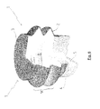
- the medical vest comprises a plurality of devices 1 located at various parts of the front 101 and back 102 of a vest 100.
- a pump 30 is arranged to provide a pressurized fluid, typically air, to the device of the vest 100.
- a pressurized fluid typically air
- ducts are connected to the pump 30 and the devices 1.
- a device 1 When a device 1 is filled with pressurized air, it inflates and generates a stroke on the patient's body.
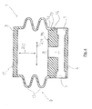
- the device 1 comprises a chamber 8 that is sealed. At least, an opening 7 allows feeding the chamber with pressurized fluid. Preferably, the same opening 7 allows emptying the chamber 8.
- the chamber 8 is delimited by walls of a head 3, a body 2 and a base 4.
- the body 2 extends between the head 3 and the base 4.
- the head 3 is configured to be, in use, turned toward the patient's body.
- an external wall of the head presents a substantially flat surface which is intended to stroke the patient's body.
- This flat surface is referred to as the impact portion 11.
- the base 4 comprises at least a port 5, 6 for establishing a communication between the chamber 8 and its opening(s) 7 and an air supply.
- the base 4 comprises a first port 5 in communication with the pressurized air supply, typically the pump 30.
- the base also comprises an additional port 6 for communication with the exterior of the vest 100. Typically, the additional port 6 is in communication with the air at room pressure.
- the ports 5, 6 of the base 4 are in communication with the chamber 8 through the opening(s) 7.
- the base 4 presents a shape substantially cylindrical.
- the ports 5, 6 extend transversally/radially inside the base 4 from an external wall of the base 4.
- the opening 7 extends substantially longitudinally, form the ports 5, 6 to the upper wall 15 of the base 4.
- Said upper wall 15 of the base defines in part the chamber 8.
- the body 2 is tightly sealed to the chamber 8 and to the head 3.
- the head 3 and the body 2 form a single, monolithic part.
- a distal end of the body 2 forms the head 3.
- a proximal end 12 of the body 2 is attached to the base 4.
- the base 4 presents at its distal end a cylindrical section 13 that is complementary of the section of the proximal end 12 of the body 2.
- the two sections 12, 13 are cylindrical and the inner diameter of the proximal end 12 of the body 2 fits the outer diameter of the distal end 13 of the base 4. There is therefore a tight fit between the body 2 and the base 4.
- the body 2 and the base 4 are glued together ensuring a perfect pneumatic seal of the two parts at the pressure used during operation.
- the chamber 8 is thus a sealed volume except through the openings 7, said volume being defined by the upper wall 15 of the base 4, the inner walls of the body 2 and the inner wall of the head 3.
- the device 1 When the device 1 is fed with pressurized fluid, typically pressurized air, it inflates and is brought, from a deflated configuration to an inflated configuration.
- pressurized fluid typically pressurized air
- the device 1 comprises elastic means arranged so that when the device 1 is not fed with pressurized air, the chamber 8 automatically retracts.
- the chamber 8 thus passes from an inflated configuration to deflated configuration.
- the fluid supply not detailed in the present invention but known from the person of ordinary skills, provides pulsed fluid under pressure.
- a particularly advantageous supply system is described in the commonly owned International patent application published with the following number WO2011086200 .
- the supply of pulsed air generates cycles of inflations and deflations of the device 1. Each inflation generates a stroke onto the patient's body.
- the elastic means allow an acceleration of the movement from the inflated configuration to the deflated configuration through pulling back the head 3 toward the base 4, such as a return spring.
- the device 1 is configured so that when passing from the device 1 deflated configuration to the inflated configuration, the device 1 expands substantially according to a single direction 200.
- This direction is the axial direction 200 along which the head 3 of the device 1 performs forth and back movements.
- This axial direction is preferably substantially perpendicular to the area of the patient's body where the device strokes. Almost all the energy of the stroke is thus delivered to the patient's body, increasing thereby the efficiency of the treatment.
- the overall energy provided to each device 1, and consequently the overall energy provided to the vest, is thus decreased. Therefore, the overall trauma undergone by the patient is thus greatly reduced while generating controlled forces applied perpendicularly to the patient's body. This allows targeting clinically important areas of the patient's body.
- the vest 100 comprising such devices 1 therefore permits the transformation of all or almost all the energy delivered to the vest 100 into focused and controlled strokes and pulsations. The overall action on the patient's body is thus much gentler and more precisely targeted than with previous systems.
- the operation of the medical vest has no or has a low effect on the patient's blood pressure which allow hypertensive patients to use the vest.
- the elastic means are comprised in bellows 9.
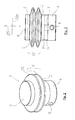
- bellows 9 are clearly illustrated on figures 2 to 6 .
- the bellows 9 retract when the device 1 passes from the inflated to the deflated configurations and expand when the devices passes from the deflated to the inflated configurations under the force of the pressure rising in the chamber 8.
- the bellows 9 tends to bring the device 1 back to the deflated configuration. It acts as a return spring.
- Figures 5 and 6 respectively illustrate bellows 9 in their retracted and expanded positions.
- the device provides a higher reactivity compared to existing systems. It can efficiently operate in a wide range of frequencies, typically frequencies comprised between 15 and 40 Hz and preferably comprised between 20Hz-30Hz. HFCWO treatments can thus be adapted to every patients and medical situations.
- the bellows 9 comprise corrugations 10, or pleats 10 having substantially annular shapes.
- the length of the body 2 increases along the axial direction 200 and the outer dimension, typically outer diameter, of the bellows 9, taken along the transverse direction, decreases when the device 1 inflates.
- the length of the body 2 decreases along the axial direction 200 and the outer dimension of the bellows 9 increases when the device 1 deflates.
- the retracted position of the elastic means or bellows 9 is also a release position.
- the body 2 can be free then retracted or shrunken in case a force is applied on it.
- the bellows 9 can further retract. This increases the comfort of the patient when breathing for instance.
- the head 3 is substantially non-deformable in regard to the deformation of the body 2.
- the impact portion 11 does not inflate when the air pressure increases in the chamber 8.
- the head 3 and the body 2 are made of an elastic material, typically silicon for instance, but the thickness of the head 3 makes it non-deformable under the pressures utilized.
- the shape of body 2 makes it non-deformable on the transverse direction. More generally, the deformation of the head 3 and body 2 through elasticity is negligible in comparison to the deformation through the extension and retraction of the bellows 9.
- the base 4 is non- deformable through elasticity during use.
- the body 2 and base 4 are preferably ductile. This notably increases the comfort of the user.
- the head 3 and body 2 are made of silicon.
- the base 4 is also made in silicon. This allows increasing the robustness of the device and its ductility, providing thereby enhanced lifespan and comfort.
- the variation of dimensions according to the axial direction 200 is higher than according to the transverse direction 201.
- the ratio 'transverse variation/axial variation' is lower than 0,8.
- this ratio is lower than 0,4.
- the maximal pressure inside the piston is comprised between 100 milllibars (10 -3 bars) and 350 millibars.
- the device is momentarily deflated and its internal pressure is ambient pressure or is lower than 30millibars.
- Very good results have been obtained for a maximal pressure comprised between 150 and 250 millibars inside the air piston. More precisely a pressure of 200 millibars provides very efficient results.
- the maximal pressure applied by the head of the device onto the patient's body is comprised between 20 and 80 millibars.
- the pressure applied onto the patient's body is practically nothing, and is more generally below 2 or 3 millibars. This allows the patient to breath during the treatment.
- the maximal pressure applied by the head of the device onto the patient's body is comprised between 40 millibars and 60 millibars. Typically, this pressure is 50 millibars.
- the head of the device has a thickness, according to the axial direction, that is comprised between 0.5mm and 4 mm.
- a thickness according to the axial direction.
- the thickness of the head of the piston is comprised between 1 mm and 3mm. Typically, for optimum effect this thickness is 2 mm. Very good results have been obtained for a silicon made head.
- the device 1 in its release configuration has a length, according to the axial direction 200, comprised between 30 and 60mm (millimeters i.e, 10 -3 meters) and preferably approximately 44mm.
- the impact portion 11 has a surface comprised between 2900 and 5500mm 2 .
- the impact surface 11 is circular and has a diameter comprised between 25mm and 50mm and more preferably of 36mm.
- the device 1 has an outer diameter, taken at the bellows 9, comprised between 35 and 65mm and approximately of 50mm.
- the device 1 In his inflated position, the device 1 has an outer diameter, taken at the bellows 9, comprised between 47 and 49 mm and approximately of 48 mm.
- the base 4 has a diameter comprised between 25 and 50 mm and preferably of 36 mm.
- the height of the base 4 is comprised between 12 and 25mm and preferably of 18mm.
- the diameter of the opening 7 is comprised between 5 and 10mm and preferably 7,6mm.
- the diameter of the ports 5, 6 is comprised between 12 and 25mm and preferably is comprised between 3 and 6mm and preferably 4,7mm.
- the height of the chamber 8, in the release position is comprised between 15 and 35mm and preferably 25,3mm.
- the height of the inflated position, in the release position, is comprised between 15 and 35mm and preferably 25,3mm.
- the height of the chamber is taken between the upper wall 15 of the base 4 and the inner wall of the head 3.
- the thickness of the impact portion 11 is comprised between 2 and 4mm and preferably 3,1mm.
- the thickness of the wall of the body 2, i.e., the wall forming the bellows 9 is comprised between 0,4 and 1,8mm and preferably between 0,6 and 1,4mm and more preferably around 1mm.
- the bellows 9 forms two corrugations 10.
- each corrugation 10 presents a curved surface.
- the radius of the curve, in the deflated configuration is comprised between 2.0 and 2.5 mm. This allows to decrease the risks of shear and enhances the lifespan of the device.
- Figure 7 illustrated an assembly of a plurality of devices 1 incorporated in a vest 100 according to the invention.
- Five devices 1 are connected to a collector 103 supplied with pressurized fluid through an input duct 104.
- the five devices share the same duct 105 and 106 for supply and emptying.
- a plurality of devices can be controlled simultaneously.
- a vest 100 according to the invention allows providing more gentle and efficient treatment.
- the robustness and lifetime of the devices incorporated in the vest 100 are particularly good.
- the device according to the invention may also be part of any medical system configured to be applied on any part of the body of a person or an animal.
- HFCWO High Frequency Chest Wall Oscillation
Landscapes
- Health & Medical Sciences (AREA)
- Epidemiology (AREA)
- Pain & Pain Management (AREA)
- Physical Education & Sports Medicine (AREA)
- Rehabilitation Therapy (AREA)
- Life Sciences & Earth Sciences (AREA)
- Animal Behavior & Ethology (AREA)
- General Health & Medical Sciences (AREA)
- Public Health (AREA)
- Veterinary Medicine (AREA)
- Percussion Or Vibration Massage (AREA)
Priority Applications (6)
| Application Number | Priority Date | Filing Date | Title |
|---|---|---|---|
| EP11306490.1A EP2594244A1 (en) | 2011-11-15 | 2011-11-15 | Medical vest for high frequency chest wall oscillation (HFCWO) system |
| CA2855885A CA2855885C (en) | 2011-11-15 | 2012-11-15 | Medical vest for high frequency chest wall oscillation (hfcwo) system |
| PCT/EP2012/072801 WO2013072446A1 (en) | 2011-11-15 | 2012-11-15 | Medical vest for high frequency chest wall oscillation (hfcwo) system |
| US14/358,661 US20150025425A1 (en) | 2011-11-15 | 2012-11-15 | Medical Vest for High Frequency Chest Wall Oscillation (HFCWO) System |
| EP12798634.7A EP2779979B1 (en) | 2011-11-15 | 2012-11-15 | Medical vest for high frequency chest wall oscillation (hfcwo) system |
| IN1267KON2014 IN2014KN01267A (enExample) | 2011-11-15 | 2012-11-15 |
Applications Claiming Priority (1)
| Application Number | Priority Date | Filing Date | Title |
|---|---|---|---|
| EP11306490.1A EP2594244A1 (en) | 2011-11-15 | 2011-11-15 | Medical vest for high frequency chest wall oscillation (HFCWO) system |
Publications (1)
| Publication Number | Publication Date |
|---|---|
| EP2594244A1 true EP2594244A1 (en) | 2013-05-22 |
Family
ID=47326074
Family Applications (2)
| Application Number | Title | Priority Date | Filing Date |
|---|---|---|---|
| EP11306490.1A Withdrawn EP2594244A1 (en) | 2011-11-15 | 2011-11-15 | Medical vest for high frequency chest wall oscillation (HFCWO) system |
| EP12798634.7A Active EP2779979B1 (en) | 2011-11-15 | 2012-11-15 | Medical vest for high frequency chest wall oscillation (hfcwo) system |
Family Applications After (1)
| Application Number | Title | Priority Date | Filing Date |
|---|---|---|---|
| EP12798634.7A Active EP2779979B1 (en) | 2011-11-15 | 2012-11-15 | Medical vest for high frequency chest wall oscillation (hfcwo) system |
Country Status (5)
| Country | Link |
|---|---|
| US (1) | US20150025425A1 (enExample) |
| EP (2) | EP2594244A1 (enExample) |
| CA (1) | CA2855885C (enExample) |
| IN (1) | IN2014KN01267A (enExample) |
| WO (1) | WO2013072446A1 (enExample) |
Cited By (1)
| Publication number | Priority date | Publication date | Assignee | Title |
|---|---|---|---|---|
| EP2967956A4 (en) * | 2013-03-15 | 2017-03-22 | Trudell Medical International | Oral mouthpiece and method for the use thereof |
Families Citing this family (14)
| Publication number | Priority date | Publication date | Assignee | Title |
|---|---|---|---|---|
| US9592177B2 (en) * | 2012-11-26 | 2017-03-14 | Sayed Nour | Circulatory flow restoration device |
| EP2803346A1 (en) * | 2013-05-15 | 2014-11-19 | Respinnovation | Medical equipment for high frequency chest wall oscillation treatment |
| WO2015073381A1 (en) * | 2013-11-14 | 2015-05-21 | Epic Medical Concepts & Innovations, Inc. | Pneumatic somatosensory stimulation device and method |
| US9901510B2 (en) | 2013-12-09 | 2018-02-27 | Brett Gene Smith | Portable apparatus for providing chest therapy |
| US12076483B2 (en) | 2013-12-09 | 2024-09-03 | Exemplar Medical LLC | Portable apparatus for providing chest therapy |
| US10959912B2 (en) | 2013-12-09 | 2021-03-30 | Exemplar Medical LLC | Portable apparatus for providing chest therapy |
| DE102016212586A1 (de) * | 2016-07-11 | 2018-01-11 | Conti Temic Microelectronic Gmbh | Pneumatische Vorrichtung |
| DE102016212606A1 (de) * | 2016-07-11 | 2018-01-11 | Continental Automotive Gmbh | Verfahren zum Herstellen einer Verstellvorrichtung für einen Fahrzeugsitz sowie Verstellvorrichtung |
| GB2567619B (en) * | 2017-10-10 | 2020-06-03 | Continental Automotive Gmbh | Pneumatic device and method for manufacturing the same |
| DE102017221921B3 (de) * | 2017-12-05 | 2019-04-25 | Conti Temic Microelectronic Gmbh | Pneumatische Vorrichtung, Fahrzeugsitz mit einer pneumatischen Vorrichtung und Verfahren zum Herstellen einer pneumatischen Vorrichtung |
| US12023300B2 (en) * | 2020-06-29 | 2024-07-02 | Hill-Rom Services Pte. Ltd. | Rotational high frequency chest wall oscillation pump |
| US12472120B2 (en) * | 2020-10-13 | 2025-11-18 | InCare, LLC | Inflation-mediated pressure therapy garment |
| CN112932939A (zh) * | 2021-03-29 | 2021-06-11 | 江西理工大学 | 一种基于气动软体结构振动的软体按摩仪 |
| US12533289B2 (en) | 2021-09-30 | 2026-01-27 | Hill-Rom Services Pte. Ltd. | Chest wall therapy garment |
Citations (4)
| Publication number | Priority date | Publication date | Assignee | Title |
|---|---|---|---|---|
| US4508107A (en) * | 1982-09-13 | 1985-04-02 | Strom Corporation | Pneumatic percussor |
| DE4207054A1 (de) * | 1992-03-06 | 1993-09-09 | Zoltan Dr Med Molnar | Vorrichtung zur mechanischen beeinflussung der lunge zur schleimloesung |
| WO2001060309A1 (en) * | 2000-02-16 | 2001-08-23 | Kenneth John Illidge | Lung treatment apparatus and methods |
| WO2011086200A1 (en) | 2010-01-18 | 2011-07-21 | Mitchell, Christine, Y.P.A. | Hfcwo vest |
Family Cites Families (27)
| Publication number | Priority date | Publication date | Assignee | Title |
|---|---|---|---|---|
| US3201111A (en) * | 1963-11-12 | 1965-08-17 | Afton Leonard | Multi-purpose, inherently biased, selfinflatable bellows |
| GB1134903A (en) * | 1966-04-12 | 1968-11-27 | Takeuchi Tekko Kk | Massaging apparatus |
| US3401607A (en) * | 1966-08-08 | 1968-09-17 | Michael L. Wortman | Reciprocating bellows |
| FR2373753A1 (fr) * | 1976-12-07 | 1978-07-07 | Bourguignonne Mec Smb | Dispositif d'allumage a securite pour bruleur ou panneau radiant |
| JPS5993524U (ja) * | 1982-12-15 | 1984-06-25 | 狩野 千世子 | コンピユ−タ操作によるエアマツト式ベツト |
| US4895352A (en) * | 1989-01-09 | 1990-01-23 | Simmons Company | Mattress or cushion spring array |
| US5558398A (en) * | 1993-11-08 | 1996-09-24 | Santos; James P. | Self-adjusting seating system |
| US5607749A (en) * | 1994-12-27 | 1997-03-04 | Strumor; Mathew A. | Ergonomic kinetic acupressure massaging system |
| US6551450B1 (en) * | 1997-10-10 | 2003-04-22 | D2Rm Corp. | Unique air and sonic massaging apparatus |
| US6212719B1 (en) * | 1997-10-10 | 2001-04-10 | D2Rm Corp. | Air massager cushioning device |
| US6254556B1 (en) * | 1998-03-12 | 2001-07-03 | Craig N. Hansen | Repetitive pressure pulse jacket |
| KR100324160B1 (ko) * | 1998-04-27 | 2002-02-16 | 구보 마쯔오 | 위치 결정 장치 및 이것을 구비하고 있는 마사지기 |
| JP3584761B2 (ja) * | 1998-11-25 | 2004-11-04 | 松下電工株式会社 | マッサージ用マット |
| JP2003022580A (ja) * | 2001-05-02 | 2003-01-24 | Victor Co Of Japan Ltd | 情報記録担体、情報記録担体の製造方法、情報記録担体再生装置及び情報記録担体記録装置 |
| DE10149418A1 (de) * | 2001-10-02 | 2003-04-17 | Norbert Egger | Fitnessgerät |
| US6916300B2 (en) * | 2002-11-14 | 2005-07-12 | Bowles Fluidics Corporation | Seat massager |
| JP2004274207A (ja) * | 2003-03-06 | 2004-09-30 | Renesas Technology Corp | バイアス電圧発生回路および差動増幅器 |
| CN101090654B (zh) * | 2004-02-13 | 2012-03-14 | 约翰·W.·威尔金森 | 离散单元人体支撑以及用其提供动态按摩的方法 |
| US7727171B2 (en) * | 2005-01-19 | 2010-06-01 | Toyota Boshoku Kabushiki Kaisha | Vehicle seats with plurality of pneumatic massaging elements |
| US7785280B2 (en) * | 2005-10-14 | 2010-08-31 | Hill-Rom Services, Inc. | Variable stroke air pulse generator |
| US7794692B2 (en) * | 2005-12-02 | 2010-09-14 | Amorfix Life Sciences Ltd. | Methods and compositions for detecting amyotrophic lateral sclerosis |
| US8460223B2 (en) * | 2006-03-15 | 2013-06-11 | Hill-Rom Services Pte. Ltd. | High frequency chest wall oscillation system |
| JP2008086338A (ja) * | 2006-09-29 | 2008-04-17 | Toyota Boshoku Corp | マッサージ用ガスバッグ |
| US8578939B1 (en) * | 2008-04-07 | 2013-11-12 | Dreamscape Medical Llc | External pressure therapy apparatus |
| DE102008019647A1 (de) * | 2008-04-18 | 2009-11-05 | Up Management Gmbh | Vorrichtung zur Diagnose, Ausführung und/oder Regulierung physiologischer Funktionen, insbesondere bei einem anästhesierten Patienten |
| US8007417B2 (en) * | 2009-04-17 | 2011-08-30 | Ergoergo, Inc. | Exercise device |
| WO2011106051A1 (en) * | 2010-02-23 | 2011-09-01 | Uam Global Llc | Ventilating element for a breathing apparatus |
-
2011
- 2011-11-15 EP EP11306490.1A patent/EP2594244A1/en not_active Withdrawn
-
2012
- 2012-11-15 US US14/358,661 patent/US20150025425A1/en not_active Abandoned
- 2012-11-15 CA CA2855885A patent/CA2855885C/en active Active
- 2012-11-15 IN IN1267KON2014 patent/IN2014KN01267A/en unknown
- 2012-11-15 EP EP12798634.7A patent/EP2779979B1/en active Active
- 2012-11-15 WO PCT/EP2012/072801 patent/WO2013072446A1/en not_active Ceased
Patent Citations (4)
| Publication number | Priority date | Publication date | Assignee | Title |
|---|---|---|---|---|
| US4508107A (en) * | 1982-09-13 | 1985-04-02 | Strom Corporation | Pneumatic percussor |
| DE4207054A1 (de) * | 1992-03-06 | 1993-09-09 | Zoltan Dr Med Molnar | Vorrichtung zur mechanischen beeinflussung der lunge zur schleimloesung |
| WO2001060309A1 (en) * | 2000-02-16 | 2001-08-23 | Kenneth John Illidge | Lung treatment apparatus and methods |
| WO2011086200A1 (en) | 2010-01-18 | 2011-07-21 | Mitchell, Christine, Y.P.A. | Hfcwo vest |
Cited By (1)
| Publication number | Priority date | Publication date | Assignee | Title |
|---|---|---|---|---|
| EP2967956A4 (en) * | 2013-03-15 | 2017-03-22 | Trudell Medical International | Oral mouthpiece and method for the use thereof |
Also Published As
| Publication number | Publication date |
|---|---|
| WO2013072446A1 (en) | 2013-05-23 |
| IN2014KN01267A (enExample) | 2015-10-16 |
| CA2855885A1 (en) | 2013-05-23 |
| CA2855885C (en) | 2019-12-31 |
| EP2779979A1 (en) | 2014-09-24 |
| EP2779979B1 (en) | 2020-11-11 |
| US20150025425A1 (en) | 2015-01-22 |
Similar Documents
| Publication | Publication Date | Title |
|---|---|---|
| EP2779979B1 (en) | Medical vest for high frequency chest wall oscillation (hfcwo) system | |
| EP2996659B1 (en) | Medical equipment for high frequency chest wall oscillation (hfcwo) treatment | |
| JP3510254B2 (ja) | 能動的加圧/減圧による心臓補助/維持装置及び方法 | |
| US11833096B2 (en) | Ambulatory respiratory assist device | |
| US10406063B2 (en) | Medical equipment for high frequency chest wall oscillation (HFCWO) treatment | |
| US8900168B2 (en) | Body surface compression with pneumatic shortening element | |
| CN101563126A (zh) | 可移动式人体脉冲装置、设备及其组合 | |
| JP2001502579A (ja) | 心肺蘇生方法とその装置 | |
| US7278978B1 (en) | Respiratory vest with inflatable bladder | |
| JP2022048134A (ja) | 胸部の円周方向圧縮と前後方向加圧を併用した機械的心肺蘇生 | |
| CN201572307U (zh) | 可携带式cpr心肺复苏器 | |
| US20040064076A1 (en) | External chest therapy blanket for infants | |
| CN210843928U (zh) | 医用俯卧位通气气垫 | |
| US20090171256A1 (en) | Portable personal device for pulmonary ventilation and resusitation at negative and positive intermittent pressures | |
| EP3531989B1 (en) | Device and method for assisting breathing in a subject | |
| CN113081426A (zh) | 一种用于咳痰辅助的外骨骼机器人及控制方法 | |
| EP2525761B1 (en) | Hfcwo vest | |
| US20260060879A1 (en) | Device for Modulation of Lymphatic Clearance and Uses Thereof | |
| CN216570764U (zh) | 新型排痰仪 | |
| US20050183722A1 (en) | External chest therapy blanket for infants | |
| EP2347747A1 (en) | Hfcwo vest | |
| US20250360051A1 (en) | Wearable device for improving vascular insufficiency to the extremities | |
| EP2347746A1 (en) | HFCWO system | |
| CN120267122A (zh) | 一种具有气囊的床垫以及气囊的控制方法 |
Legal Events
| Date | Code | Title | Description |
|---|---|---|---|
| PUAI | Public reference made under article 153(3) epc to a published international application that has entered the european phase |
Free format text: ORIGINAL CODE: 0009012 |
|
| AK | Designated contracting states |
Kind code of ref document: A1 Designated state(s): AL AT BE BG CH CY CZ DE DK EE ES FI FR GB GR HR HU IE IS IT LI LT LU LV MC MK MT NL NO PL PT RO RS SE SI SK SM TR |
|
| AX | Request for extension of the european patent |
Extension state: BA ME |
|
| STAA | Information on the status of an ep patent application or granted ep patent |
Free format text: STATUS: THE APPLICATION IS DEEMED TO BE WITHDRAWN |
|
| 18D | Application deemed to be withdrawn |
Effective date: 20131123 |