EP2593740B1 - Kühlvorrichtung für heisses schüttgut - Google Patents
Kühlvorrichtung für heisses schüttgut Download PDFInfo
- Publication number
- EP2593740B1 EP2593740B1 EP11728831.6A EP11728831A EP2593740B1 EP 2593740 B1 EP2593740 B1 EP 2593740B1 EP 11728831 A EP11728831 A EP 11728831A EP 2593740 B1 EP2593740 B1 EP 2593740B1
- Authority
- EP
- European Patent Office
- Prior art keywords
- gas flow
- cooling tower
- cooling
- cooling apparatus
- bulk goods
- Prior art date
- Legal status (The legal status is an assumption and is not a legal conclusion. Google has not performed a legal analysis and makes no representation as to the accuracy of the status listed.)
- Active
Links
Images

Classifications
-
- F—MECHANICAL ENGINEERING; LIGHTING; HEATING; WEAPONS; BLASTING
- F27—FURNACES; KILNS; OVENS; RETORTS
- F27D—DETAILS OR ACCESSORIES OF FURNACES, KILNS, OVENS OR RETORTS, IN SO FAR AS THEY ARE OF KINDS OCCURRING IN MORE THAN ONE KIND OF FURNACE
- F27D15/00—Handling or treating discharged material; Supports or receiving chambers therefor
- F27D15/02—Cooling
- F27D15/0286—Cooling in a vertical, e.g. annular, shaft
-
- C—CHEMISTRY; METALLURGY
- C22—METALLURGY; FERROUS OR NON-FERROUS ALLOYS; TREATMENT OF ALLOYS OR NON-FERROUS METALS
- C22B—PRODUCTION AND REFINING OF METALS; PRETREATMENT OF RAW MATERIALS
- C22B1/00—Preliminary treatment of ores or scrap
- C22B1/26—Cooling of roasted, sintered, or agglomerated ores
-
- C—CHEMISTRY; METALLURGY
- C22—METALLURGY; FERROUS OR NON-FERROUS ALLOYS; TREATMENT OF ALLOYS OR NON-FERROUS METALS
- C22B—PRODUCTION AND REFINING OF METALS; PRETREATMENT OF RAW MATERIALS
- C22B1/00—Preliminary treatment of ores or scrap
- C22B1/14—Agglomerating; Briquetting; Binding; Granulating
- C22B1/16—Sintering; Agglomerating
- C22B1/20—Sintering; Agglomerating in sintering machines with movable grates
Definitions
- Such a cooling device is known from JP 55 119 138 A and also from the JP 10 265 858 A is known.
- the object of the present invention is to provide possibilities by means of which the heat generated during the cooling of hot bulk waste heat can be used more efficiently.
- the gas flow guides form an angle of inclination with the horizontal, so that the gas flow guides increase toward the main axis.
- the efficiency in exploiting the waste heat can be further optimized. This is especially true when the angle of inclination is chosen so that it corresponds approximately to the bulk material angle that forms the hot bulk material with the horizontal.
- the angle of inclination is therefore preferably between 20 ° and 45 °, usually between 25 ° and 35 °.
- outlets are arranged exclusively on the underside of the gas flow guides.
- An arrangement of the outlets exclusively on the underside of the gas flow guides can be achieved, for example, in that the gas flow guides each have two side areas and a roof area bridging the side areas, that the side areas are essentially vertical, and that the roof area has the shape of an inverted "V" in cross section. having.
- the gas flow guides extend to the main axis or up to a arranged on the main axis hub. This ensures that the hot bulk material flows through practically throughout the cross section of the cooling tower of the gas stream and is cooled.
- the discharge device is arranged in the tower outer wall.
- the feeding device can be designed without regard to the design of the discharge device.
- the feed device is designed as a rotary chute. This embodiment achieves a better distribution of the hot bulk material over the cross-sectional area of the cooling tower.
- This embodiment is particularly advantageous when the gas conveyor is designed as a fan. Through them it is achieved that leakage losses of the gas stream are minimized.
- a cooling device for cooling hot bulk material 1 (for example small sintered iron ore balls) has a cooling tower 2 with a vertical main axis 3.
- the hot bulk material 1 is cooled by means of a gas flow 4.
- the cooling device has a feed device 5. By means of the feeder 5, the hot bulk material 1 of poured into the top of the cooling tower 2. The hot bulk material 1 is thereby accumulated in the cooling tower 2.
- the feeder 5 can according to the representation of FIG. 1 For example, be designed as a rotary chute, which is rotated at a predetermined speed n.
- the speed n is usually relatively small.
- an effective radius r with which the feeder 5 distributes the hot bulk material 1, is generally considerably smaller than the radius R of the cooling tower 2.
- the effective radius r at which the feeder 5 distributes the hot bulk material 1 is usually a maximum of 30% of the radius R of the cooling tower 2.
- a discharge cone is formed in the vicinity of the tower outer wall 6 (that is, the vertical or substantially vertical wall of the cooling tower 2).
- the cone has a typical bulk material angle ⁇ .
- the bulk material angle ⁇ is - depending on the bulk material 1 - usually between about 30 ° and about 38 °.
- the cooling device furthermore has a removal device 7.
- the removal device 7 By means of the removal device 7, the bulk material 1 is taken down from the cooling tower 2. As a result, the bulk material 1 remaining in the cooling tower 2 slides downwards.
- the removal device 7 may for example be designed as a push table, which moves in a circle.
- the cooling device furthermore has a gas delivery device 8.
- the gas delivery device 8 By means of the gas delivery device 8, the gas stream 4 is conveyed through the cooling tower 2.
- the gas conveying device 8 is preferably designed as a fan. In principle, however, a suction device is possible.
- the cooling device furthermore has a discharge device 9. Via the discharge device 9, the gas stream 4 is discharged from the cooling tower 2.
- the bulk material 1 When the bulk material 1 is supplied to the cooling tower 2, it is hot. Typical temperatures are up to 900 ° C. When the bulk material 1 is removed from the cooling tower 2, it is (relatively) cold. Typical temperatures are between 70 ° C and 150 ° C.
- the cooling of the hot bulk material 1 takes place essentially by means of the conveyed through the cooling tower 2 gas stream 4. Accordingly, the gas stream 4 in the cold state (temperature typically equal to ambient temperature) in the cooling tower 2 passed and hot (temperatures typically between 600 ° C and 800 ° C) discharged from the cooling tower 2.
- the cooling tower 2 is usually arranged in a building 10.
- the building 10 has side walls 11.
- the side walls 11 extend, starting from below, to an intermediate height h of the cooling tower 2.
- the intermediate height h, relative to the total height H of the cooling tower 2, is generally between 40% and 60% of the total height H of the cooling tower 2 ,
- the gas delivery device 8 may be arranged within the building 10, in particular if it is designed as a fan. As a rule, however, the gas delivery device 8 is arranged outside the building 10.
- the discharge device 9 is arranged in the upper region of the cooling tower 2 and thus outside of the building 10.
- the discharge device 9 can be arranged on the upper side 12 of the cooling tower 2.
- the discharge device 9 is arranged in the tower outer wall 6, that is laterally.
- a plurality of gas flow guides 13 is arranged.
- the minimum number of gas flow guides 13 two.
- at least six gas flow guides 13 are present.
- the maximum number of gas flow guides 13 is not limited in principle. In general, however, numerical values of 40 are not exceeded. In most cases, the number of gas flow guides 13 is between 8 and 16.
- the gas flow guides 13 are according to FIG. 1 designed as elongated guides. They have inlets 14 which are arranged in the tower outer wall 6. Starting from the inlets 14, the gas flow guides 13 extend radially inward towards the main axis 3 of the cooling tower 2.
- the course of the gas flow guides 13 may, for example, be spoke-like (shown), crescent-shaped, etc. Other courses are possible. It is only important that the distance to the main axis 3 of the cooling tower 2 along the longitudinal extent of the gas flow guides decreases.
- the gas flow guides 13 have - over their seen in their respective extension direction length - outlets 15 for the gas stream 4.
- the - still cold at this time - gas stream 4 is therefore introduced via the inlets 14 in the gas flow guides 13 and passed from there via the outlets 15 in the cooling tower 2 located in the hot bulk material.
- the cross section of the gas flow guides 13 can be seen over its length constant. However, the cross-section of the gas flow guides 13 preferably decreases as shown in FIG FIG. 1 to the main axis 3 of the cooling tower 2 to.
- the gas flow guides 13 are arranged in the direction of the main axis 3 of the cooling tower 2 in the central region 16 of the cooling tower 2.
- the central region 16 extends from about 30% of the total height H of the cooling tower 2 to about 70% of the total height H of the cooling tower 2.
- the gas flow guides 13 are arranged below the discharge device 9.
- the inlets 14 are further arranged below the roof 17 of the building 10.
- the side walls 11 of the building 10 therefore extend beyond the inlets 14 of the gas flow guides 13. Due to the arrangement of the gas flow guides 13 below the discharge 9 flows through the gas stream 4 located in the cooling tower 2 hot bulk material 1 from bottom to top (countercurrent principle).
- the gas flow guides 13 can in principle run horizontally.
- the gas flow guides 13 form according to the illustration of FIG. 1 with the horizontal an inclination angle ⁇ , so that the gas flow guides 13 to the main axis 3 of the cooling tower 2 to rise.
- the inclination angle ⁇ may be determined as needed.
- the inclination angle ⁇ is chosen so that it corresponds approximately to the bulk material angle a.
- the angle of inclination ⁇ should be between 20 ° and 45 °. Particular preference is given to values between 28 ° and 40 °.
- the outlets 15 in the gas flow guides 13 are arranged exclusively on the underside of the gas flow guides 13.
- the gas flow guides 13 preferably each have two side areas 18 and a roof area 19.
- the side areas 18 are substantially vertical.
- the roof area 19 bridges over the side areas 18. It preferably has the shape of an inverted "V" in cross section.
- the gas flow guides 13 end in front of the main axis 3 of the cooling tower 2.
- the gas flow guides 13 preferably extend as far as the main axis 3 (or up to a "hub" 20 arranged in the region of the main axis 3 of the cooling tower 2).
- the removal device 7 is usually arranged within the building 10 as well.
- the removed from the cooling tower 2 bulk material 1 is therefore initially (still) within the building 10.
- the cooling device therefore has in this case a device by means of which the removed from the cooling tower 2 bulk material 1 is discharged from the building 10.
- This device is according to FIG. 3 preferably formed as endless conveyor 21.
- the endless conveyor 21 has trough-like container 23.
- the containers 23 have transversely to the conveying direction x seen in accordance with FIG. 4 a container cross section. Viewed in the conveying direction x, they have according to FIG. 3 a container length 1 on.
- the endless conveyor 21 may be designed for this purpose as a so-called Wellkantgurt with transverse studs.
- the passage areas 22 through which the endless conveyor 21 (more specifically, the containers 23) exit the building 10 and enter the building 10 are preferably formed as a tunnel.
- the tunnels 22 have a cross-section that corresponds to FIG FIG. 4 adapted to the container cross-section.
- sealing lips or the like may be arranged on the sides of the tunnel walls.
- the tunnels 22 furthermore each have, in the conveying direction x, a tunnel length L which is greater than the container length 1.
- the tunnel length L is even at least twice as large as the container length 1, for example about 2.5 times to about 3.5 times as large.
- the present invention has many advantages.
- the cooling of the hot bulk material 1 in the cooling tower 2 is possible with a superior efficiency.
- the cooling device according to the invention has only a few mechanical components. It is therefore cheaper to purchase and to maintain than the systems of the prior art.
- a smaller amount of cooling air is required than in the prior art.
- the gas delivery device 8 can therefore be smaller in size than in comparable cooling devices of the prior art.
- any of the discharge device 9 downstream cleaning and dedusting devices can be dimensioned smaller than in the prior art.
Landscapes
- Engineering & Computer Science (AREA)
- Life Sciences & Earth Sciences (AREA)
- Environmental & Geological Engineering (AREA)
- General Life Sciences & Earth Sciences (AREA)
- Geochemistry & Mineralogy (AREA)
- Geology (AREA)
- Mechanical Engineering (AREA)
- Chemical & Material Sciences (AREA)
- Materials Engineering (AREA)
- Manufacturing & Machinery (AREA)
- Metallurgy (AREA)
- Organic Chemistry (AREA)
- General Engineering & Computer Science (AREA)
- Furnace Details (AREA)
- Processing Of Solid Wastes (AREA)
- Feeding, Discharge, Calcimining, Fusing, And Gas-Generation Devices (AREA)
Description
- Die vorliegende Erfindung betrifft eine Kühlvorrichtung für heißes Schüttgut,
- wobei die Kühlvorrichtung einen Kühlturm mit einer vertikalen Hauptachse aufweist, in dem das heiße Schüttgut mittels eines Gasstroms gekühlt wird,
- wobei die Kühlvorrichtung eine Zuführeinrichtung aufweist, mittels derer das heiße Schüttgut von oben in den Kühlturm geschüttet wird, so dass das heiße Schüttgut im Kühlturm angehäuft wird,
- wobei die Kühlvorrichtung eine Entnahmeeinrichtung aufweist, mittels derer das Schüttgut im kalten Zustand unten aus dem Kühlturm entnommen wird, so dass das im Kühlturm verbleibende Schüttgut nach unten nachrutscht,
- wobei die Kühlvorrichtung eine Gasfördereinrichtung aufweist, mittels derer der Gasstrom durch den Kühlturm gefördert wird,
- wobei die Kühlvorrichtung eine Abführeinrichtung aufweist, über die der Gasstrom aus dem Kühlturm abgeführt wird.
- Eine derartige Kühlvorrichtung ist aus der
JP 55 119 138 A JP 10 265 858 A - Aus der
JP 58 077 537 A - wobei die Kühlvorrichtung einen Kühlturm mit einer vertikalen Hauptachse aufweist, in dem das heiße Schüttgut mittels eines Gasstroms gekühlt wird,
- wobei die Kühlvorrichtung eine Gasfördereinrichtung aufweist, mittels derer ein Gasstrom durch den Kühlturm gefördert wird,
- wobei die Kühlvorrichtung eine Abführeinrichtung aufweist, über die der Gasstrom aus dem Kühlturm abgeführt wird.
- Beim Kühlen von heißem Schüttgut - beispielsweise gesintertem Eisenerz - ist man bestrebt, die dabei entstehende Abwärme möglichst effizient auszunutzen.
- Stand der Technik sind Kreuzstromkühler in Form von Ringabsenkkühlern oder Ringabstreifkühlern. Bei Ringabsenkkühlern ist jedoch die Abwärmenutzung auf das erste Drittel des Kühlers beschränkt, da die Ablufttemperatur ständig abnimmt. Bei Ringabstreifkühlern entsteht ein Gemisch aus heißer und warmer Abluft, dessen Temperatur grundsätzlich nicht so hoch wie maximal möglich ist, so dass ebenfalls die Effizienz der Abwärmenutzung verschlechtert ist.
- Die Aufgabe der vorliegenden Erfindung besteht darin, Möglichkeiten zu schaffen, mittels derer die beim Kühlen von heißem Schüttgut entstehende Abwärme effizienter nutzbar ist.
- Die Aufgabe wird durch eine Kühlvorrichtung für heißes Schüttgut mit den Merkmalen des Anspruchs 1 gelöst. Vorteilhafte Ausgestaltungen der erfindungsgemäßen Kühlvorrichtung sind Gegenstand der abhängigen Ansprüche 2 bis 9.
- Erfindungsgemäß ist vorgesehen, eine Kühlvorrichtung für heißes Schüttgut der eingangs genannten Art derart auszugestalten,
- dass im Kühlturm eine Mehrzahl von Gasstromführungen angeordnet ist, die sich, ausgehend von in der Turmaußenwand angeordneten Einlässen, nach radial innen auf die Hauptachse zu erstrecken,
- dass die Gasstromführungen als langgestreckte Führungen ausgebildet sind, die über ihre in ihrer jeweiligen Erstreckungsrichtung gesehene Länge Auslässe für den Gasstrom aufweisen, so dass der Gasstrom in das im Kühlturm befindliche heiße Schüttgut geleitet wird,
- dass die Gasstromführungen in Richtung der Hauptachse gesehen im Mittelbereich des Kühlturms angeordnet sind und die Abführeinrichtung im oberen Bereich des Kühlturms angeordnet ist, so dass der Gasstrom das im Kühlturm befindliche heiße Schüttgut von unten nach oben durchströmt.
- Durch diese Ausgestaltung wird erreicht, dass der Gasstrom das heiße Schüttgut im Gegenstrom durchströmt. Ein Vermischen von heißer und warmer Abluft ist nicht mehr möglich.
- Vorzugsweise ist vorgesehen, dass die Gasstromführungen mit der Horizontalen einen Neigungswinkel bilden, so dass die Gasstromführungen auf die Hauptachse zu ansteigen. Durch diese Ausgestaltung kann der Wirkungsgrad beim Ausnutzen der Abwärme noch weiter optimiert werden. Dies gilt ganz besonders, wenn der Neigungswinkel derart gewählt ist, dass er in etwa dem Schüttgutwinkel entspricht, den das heiße Schüttgut mit der Horizontalen bildet. Der Neigungswinkel liegt daher vorzugsweise zwischen 20° und 45°, meist zwischen 25° und 35°.
- Vorzugsweise ist vorgesehen, dass die Auslässe ausschließlich auf der Unterseite der Gasstromführungen angeordnet sind. Durch diese Ausgestaltung wird erreicht, dass die Gefahr einer Verstopfung der Auslässe minimiert oder sogar ganz vermieden wird.
- Eine Anordnung der Auslässe ausschließlich auf der Unterseite der Gasstromführungen kann beispielsweise dadurch erreicht werden, dass die Gasstromführungen jeweils zwei Seitenbereiche und einen die Seitenbereiche überbrückenden Dachbereich aufweisen, dass die Seitenbereiche im Wesentlichen vertikal verlaufen und dass der Dachbereich im Querschnitt die Form eines invertierten "V" aufweist.
- Vorzugsweise erstrecken sich die Gasstromführungen bis zur Hauptachse oder bis zu einer auf der Hauptachse angeordneten Nabe. Dadurch wird erreicht, dass das heiße Schüttgut praktisch im gesamten Querschnitt des Kühlturms von dem Gasstrom durchströmt und gekühlt wird.
- Vorzugsweise ist die Abführeinrichtung in der Turmaußenwand angeordnet. Durch diese Ausgestaltung wird erreicht, dass die Zuführeinrichtung ohne Rücksicht auf die Ausgestaltung der Abführeinrichtung ausgelegt werden kann.
- In einer bevorzugten Ausgestaltung der vorliegenden Erfindung ist die Zuführeinrichtung als Drehschurre ausgebildet. Durch diese Ausgestaltung wird eine bessere Verteilung des heißen Schüttguts über die Querschnittfläche des Kühlturms erreicht.
- Vorzugsweise ist vorgesehen,
- dass der Kühlturm in einem Gebäude angeordnet ist, dessen Seitenwände sich, ausgehend von unten, bis über die Einlässe erstrecken,
- dass die Entnahmeeinrichtung innerhalb des Gebäudes angeordnet ist, so dass das aus dem Kühlturm entnommene Schüttgut sich zunächst innerhalb des Gebäudes befindet,
- dass die Kühlvorrichtung eine Endlosfördereinrichtung aufweist, mittels derer das aus dem Kühlturm entnommene Schüttgut aus dem Gebäude abgeführt wird,
- dass die Endlosfördereinrichtung wannenartige Behälter aufweist, die quer zur Förderrichtung gesehen einen Behälterquerschnitt und in Förderrichtung gesehen eine Behälterlänge aufweisen,
- dass die Behälter durch zwei als Tunnel ausgebildete Durchtrittsbereiche aus dem Gebäude austreten und in das Gebäude eintreten und
- dass der Querschnitt der Tunnel an den Behälterquerschnitt angepasst ist und die Tunnel in Förderrichtung gesehen jeweils eine Tunnellänge aufweisen, die größer als die Behälterlänge ist.
- Diese Ausgestaltung ist insbesondere dann von Vorteil, wenn die Gasfördereinrichtung als Gebläse ausgebildet ist. Durch sie wird erreicht, dass Leckageverluste des Gasstroms minimiert werden.
- Weitere Vorteile und Einzelheiten ergeben sich aus der nachfolgenden Beschreibung eines Ausführungsbeispiels in Verbindung mit den Zeichnungen. Es zeigen in Prinzipdarstellung:
- FIG 1
- eine Kühlvorrichtung für heißes Schüttgut,
- FIG 2
- eine Gasstromführung im Querschnitt,
- FIG 3
- eine Endlosfördereinrichtung von der Seite und
- FIG 4
- einen Durchtrittsbereich mit einem wannenförmigen Behälter im Querschnitt.
- Gemäß
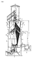
FIG 1 weist eine Kühlvorrichtung zum Kühlen von heißem Schüttgut 1 (beispielsweise kleinen Kügelchen von gesintertem Eisenerz) einen Kühlturm 2 mit einer vertikalen Hauptachse 3 auf. In dem Kühlturm 2 wird das heiße Schüttgut 1 mittels eines Gasstroms 4 gekühlt. - Die Kühlvorrichtung weist eine Zuführeinrichtung 5 auf. Mittels der Zuführeinrichtung 5 wird das heiße Schüttgut 1 von oben in den Kühlturm 2 geschüttet. Das heiße Schüttgut 1 wird dadurch im Kühlturm 2 angehäuft.
- Die Zuführeinrichtung 5 kann entsprechend der Darstellung von
FIG 1 beispielsweise als Drehschurre ausgebildet sein, die mit einer vorbestimmten Drehzahl n rotiert wird. Die Drehzahl n ist in der Regel relativ klein. Beispielsweise kann die Drehzahl n im Falle der Ausgestaltung der Zuführeinrichtung 5 als Drehschurre im Bereich zwischen 0,25 Umdrehungen/Minute und einer Umdrehung/Minute liegen. - Durch die Ausbildung als Drehschurre wird das heiße Schüttgut 1 besser über den (horizontalen) Querschnitt des Kühlturms 2 verteilt. Ein wirksamer Radius r, mit dem die Zuführeinrichtung 5 das heiße Schüttgut 1 verteilt, ist jedoch in der Regel erheblich kleiner als der Radius R des Kühlturms 2. Insbesondere beträgt der wirksame Radius r, mit dem die Zuführeinrichtung 5 das heiße Schüttgut 1 verteilt, in der Regel maximal 30 % des Radius R des Kühlturms 2. Meist werden sogar nur Zahlenwerte erreicht, die zwischen 10 % und 25 % liegen. In der Nähe der Turmaußenwand 6 (d. h. der vertikalen bzw. im Wesentlichen vertikalen Wand des Kühlturms 2) bildet sich daher ein Schüttungskegel aus. Der Schüttungskegel weist einen typischen Schüttgutwinkel α auf. Der Schüttgutwinkel α liegt - je nach Schüttgut 1 - in der Regel zwischen ca. 30° und ca. 38°.
- Die Kühlvorrichtung weist weiterhin eine Entnahmeeinrichtung 7 auf. Mittels der Entnahmeeinrichtung 7 wird das Schüttgut 1 unten aus dem Kühlturm 2 entnommen. Dadurch rutscht das im Kühlturm 2 verbleibende Schüttgut 1 nach unten nach. Die Entnahmeeinrichtung 7 kann beispielsweise als Schubtisch ausgebildet sein, der sich kreisförmig bewegt.
- Die Kühlvorrichtung weist weiterhin eine Gasfördereinrichtung 8 auf. Mittels der Gasfördereinrichtung 8 wird der Gasstrom 4 durch den Kühlturm 2 gefördert. Die Gasfördereinrichtung 8 ist vorzugsweise als Gebläse ausgebildet. Prinzipiell ist jedoch auch eine Saugvorrichtung möglich.
- Die Kühlvorrichtung weist weiterhin eine Abführeinrichtung 9 auf. Über die Abführeinrichtung 9 wird der Gasstrom 4 aus dem Kühlturm 2 abgeführt.
- Wenn das Schüttgut 1 dem Kühlturm 2 zugeführt wird, ist es heiß. Typische Temperaturen liegen bei bis zu 900 °C. Wenn das Schüttgut 1 aus dem Kühlturm 2 entnommen wird, ist es (relativ) kalt. Typische Temperaturen liegen zwischen 70 °C und 150 °C. Das Abkühlen des heißen Schüttguts 1 erfolgt im Wesentlichen mittels des durch den Kühlturm 2 geförderten Gasstroms 4. Demzufolge wird der Gasstrom 4 im kalten Zustand (Temperatur typisch gleich Umgebungstemperatur) in den Kühlturm 2 geleitet und im heißen Zustand (Temperaturen typisch zwischen 600 °C und 800 °C) aus dem Kühlturm 2 abgeführt.
- Der Kühlturm 2 ist in der Regel in einem Gebäude 10 angeordnet. Das Gebäude 10 weist Seitenwände 11 auf. Die Seitenwände 11 erstrecken sich, ausgehend von unten, bis zu einer Zwischenhöhe h des Kühlturms 2. Die Zwischenhöhe h liegt, bezogen auf die gesamte Höhe H des Kühlturms 2, in der Regel zwischen 40 % und 60 % der gesamten Höhe H des Kühlturms 2.
- Die Gasfördereinrichtung 8 kann - insbesondere, wenn sie als Gebläse ausgebildet ist - innerhalb des Gebäudes 10 angeordnet sein. In der Regel ist die Gasfördereinrichtung 8 jedoch außerhalb des Gebäudes 10 angeordnet. Die Abführeinrichtung 9 ist im oberen Bereich des Kühlturms 2 angeordnet und damit außerhalb des Gebäudes 10.
- Die Abführeinrichtung 9 kann auf der Oberseite 12 des Kühlturms 2 angeordnet sein. Vorzugsweise ist die Abführeinrichtung 9 in der Turmaußenwand 6 angeordnet, also seitlich.
- Im Kühlturm 2 ist eine Mehrzahl von Gasstromführungen 13 angeordnet. Prinzipiell beträgt die Minimalanzahl an Gasstromführungen 13 zwei. In der Praxis sind jedoch mindestens sechs Gasstromführungen 13 vorhanden. Die Maximalzahl an Gasstromführungen 13 ist prinzipiell nicht begrenzt. In der Regel werden jedoch Zahlenwerte von 40 nicht überschritten. Meist beträgt die Anzahl an Gasstromführungen 13 zwischen 8 und 16.
- Die Gasstromführungen 13 sind gemäß
FIG 1 als langgestreckte Führungen ausgebildet. Sie weisen Einlässe 14 auf, die in der Turmaußenwand 6 angeordnet sind. Ausgehend von den Einlässen 14, erstrecken sich die Gasstromführungen 13 nach radial innen auf die Hauptachse 3 des Kühlturms 2 zu. Der Verlauf der Gasstromführungen 13 kann beispielsweise speichenartig (dargestellt), sichelförmig usw. sein. Auch andere Verläufe sind möglich. Es kommt nur darauf an, dass der Abstand zur Hauptachse 3 des Kühlturms 2 entlang der Längserstreckung der Gasstromführungen abnimmt. - Die Gasstromführungen 13 weisen - über ihre in ihrer jeweiligen Erstreckungsrichtung gesehene Länge - Auslässe 15 für den Gasstrom 4 auf. Der - zu diesem Zeitpunkt noch kalte - Gasstrom 4 wird daher über die Einlässe 14 in die Gasstromführungen 13 eingeleitet und von dort über die Auslässe 15 in das im Kühlturm 2 befindliche heiße Schüttgut geleitet.
- Der Querschnitt der Gasstromführungen 13 kann über ihre Länge gesehen konstant sein. Vorzugsweise verringert sich der Querschnitt der Gasstromführungen 13 jedoch entsprechend der Darstellung von
FIG 1 auf die Hauptachse 3 des Kühlturms 2 zu. - Die Gasstromführungen 13 sind in Richtung der Hauptachse 3 des Kühlturms 2 gesehen im Mittelbereich 16 des Kühlturms 2 angeordnet. Der Mittelbereich 16 erstreckt sich von ca. 30 % der gesamten Höhe H des Kühlturms 2 bis ca. 70 % der gesamten Höhe H des Kühlturms 2. Unabhängig von der genauen Anordnung der Gasstromführungen 13 sind jedoch die Gasstromführungen 13 unterhalb der Abführeinrichtung 9 angeordnet. Wenn der Kühlturm 2 in dem Gebäude 10 angeordnet ist, sind die Einlässe 14 weiterhin unterhalb des Dachs 17 des Gebäudes 10 angeordnet. Die Seitenwände 11 des Gebäudes 10 erstrecken sich daher bis über die Einlässe 14 der Gasstromführungen 13. Auf Grund der Anordnung der Gasstromführungen 13 unterhalb der Abführeinrichtung 9 durchströmt der Gasstrom 4 das im Kühlturm 2 befindliche heiße Schüttgut 1 von unten nach oben (Gegenstromprinzip).
- Die Gasstromführungen 13 können prinzipiell horizontal verlaufen. Vorzugsweise bilden die Gasstromführungen 13 jedoch entsprechend der Darstellung von
FIG 1 mit der Horizontalen einen Neigungswinkel β, so dass die Gasstromführungen 13 auf die Hauptachse 3 des Kühlturms 2 zu ansteigen. Der Neigungswinkel β kann nach Bedarf bestimmt sein. Vorzugsweise ist der Neigungswinkel β so gewählt, dass er in etwa dem Schüttgutwinkel a entspricht. Insbesondere sollte der Neigungswinkel β zwischen 20° und 45° liegen. Besonders bevorzugt sind Werte zwischen 28° und 40°. - Prinzipiell ist es möglich, die Auslässe 15 in den Gasstromführungen 13 an beliebiger Stelle vorzusehen. Bevorzugt ist jedoch, dass die Auslässe 15 entsprechend der Darstellung von
FIG 2 ausschließlich auf der Unterseite der Gasstromführungen 13 angeordnet sind. Insbesondere können die Gasstromführungen 13, wie inFIG 2 dargestellt, auf ihrer gesamten Unterseite offen sein. In diesem Fall weisen die Gasstromführungen 13 vorzugsweise jeweils zwei Seitenbereiche 18 und einen Dachbereich 19 auf. Die Seitenbereiche 18 verlaufen im Wesentlichen vertikal. Der Dachbereich 19 überbrückt die Seitenbereiche 18. Er weist vorzugsweise im Querschnitt die Form eines invertierten "V" auf. - Es ist möglich, dass die Gasstromführungen 13 vor der Hauptachse 3 des Kühlturms 2 enden. Vorzugsweise erstrecken sich die Gasstromführungen 13 jedoch bis zur Hauptachse 3 (bzw. bis zu einer im Bereich der Hauptachse 3 des Kühlturms 2 angeordneten "Nabe" 20).
- Wenn der Kühlturm 2 innerhalb des Gebäudes 10 angeordnet ist, ist in der Regel auch die Entnahmeeinrichtung 7 innerhalb des Gebäudes 10 angeordnet. Das aus dem Kühlturm 2 entnommene Schüttgut 1 befindet sich daher zunächst (noch) innerhalb des Gebäudes 10. Die Kühlvorrichtung weist daher in diesem Fall eine Einrichtung auf, mittels derer das aus dem Kühlturm 2 entnommene Schüttgut 1 aus dem Gebäude 10 abgeführt wird. Diese Einrichtung ist gemäß
FIG 3 vorzugsweise als Endlosfördereinrichtung 21 ausgebildet. - Insbesondere im Falle der Ausbildung der Gasfördereinrichtung 8 als Gebläse, wenn also der Gasstrom 4 zunächst in das Gebäude 10 geblasen wird und erst von dort aus über die Einlässe 14 in die Gasstromführungen 13 eingeleitet wird, sollten Durchtrittsbereiche 22, in denen die Endlosfördereinrichtung 21 aus dem Gebäude 10 austritt und wieder in das Gebäude 10 eintritt, relativ dicht sein. Zu diesem Zweck ist gemäß
FIG 3 vorgesehen, dass die Endlosfördereinrichtung 21 wannenartige Behälter 23 aufweist. Die Behälter 23 weisen quer zur Förderrichtung x gesehen gemäßFIG 4 einen Behälterquerschnitt auf. In Förderrichtung x gesehen weisen sie gemäßFIG 3 eine Behälterlänge 1 auf. Beispielsweise kann die Endlosfördereinrichtung 21 zu diesem Zweck als so genannter Wellkantgurt mit Querstollen ausgebildet sein. - Die Durchtrittsbereiche 22, durch die hindurch die Endlosfördereinrichtung 21 (genauer: die Behälter 23) aus dem Gebäude 10 austreten und in das Gebäude 10 eintreten, sind vorzugsweise als Tunnel ausgebildet. Die Tunnel 22 weisen einen Querschnitt auf, der gemäß
FIG 4 an den Behälterquerschnitt angepasst ist. Gegebenenfalls können an den Seiten der Tunnelwände Dichtungslippen oder dergleichen angeordnet sein. Die Tunnel 22 weisen weiterhin in Förderrichtung x gesehen jeweils eine Tunnellänge L auf, die größer als die Behälterlänge 1 ist. Vorzugsweise ist die Tunnellänge L sogar mindestens zweimal so groß wie die Behälterlänge 1, beispielsweise ca. 2,5-mal bis ca. 3,5-mal so groß. - Die vorliegende Erfindung weist viele Vorteile auf. Insbesondere ist das Kühlen des heißen Schüttguts 1 im Kühlturm 2 mit einem überlegenen Wirkungsgrad möglich. Weiterhin weist die erfindungsgemäße Kühlvorrichtung nur wenige mechanische Bauteile auf. Sie ist daher sowohl in der Anschaffung als auch in der Wartung günstiger als die Systeme des Standes der Technik. Darüber hinaus wird bei der vorliegenden Erfindung eine geringere Menge an Kühlluft benötigt als im Stand der Technik. Die Gasfördereinrichtung 8 kann daher kleiner dimensioniert sein als bei vergleichbaren Kühlvorrichtungen des Standes der Technik. Auch etwaige der Abführeinrichtung 9 nachgeordnete Reinigungs- und Entstaubungseinrichtungen können kleiner dimensioniert werden als im Stand der Technik.
- Die obige Beschreibung dient ausschließlich der Erläuterung der vorliegenden Erfindung. Der Schutzumfang der vorliegenden Erfindung soll hingegen ausschließlich durch die beigefügten Ansprüche bestimmt sein.
Claims (10)
- Kühlvorrichtung für heißes Schüttgut (1),- wobei die Kühlvorrichtung einen Kühlturm (2) mit einer vertikalen Hauptachse (3) aufweist, in dem das heiße Schüttgut (1) mittels eines Gasstroms (4) gekühlt wird,- wobei die Kühlvorrichtung eine Zuführeinrichtung (5) aufweist, mittels derer das heiße Schüttgut (1) von oben in den Kühlturm (2) geschüttet wird, so dass das heiße Schüttgut (1) im Kühlturm (2) angehäuft wird,- wobei die Kühlvorrichtung eine Entnahmeeinrichtung (7) aufweist, mittels derer das Schüttgut (1) im kalten Zustand unten aus dem Kühlturm (2) entnommen wird, so dass das im Kühlturm (2) verbleibende Schüttgut (1) nach unten nachrutscht,- wobei die Kühlvorrichtung eine Gasfördereinrichtung (8) aufweist, mittels derer der Gasstrom (4) durch den Kühlturm (2) gefördert wird,- wobei die Kühlvorrichtung eine Abführeinrichtung (9) aufweist, über die der Gasstrom (4) aus dem Kühlturm (2) abgeführt wird,- wobei im Kühlturm (2) eine Mehrzahl von Gasstromführungen (13) angeordnet ist, die sich, ausgehend von in der Turmaußenwand (6) angeordneten Einlässen (14), nach radial innen auf die Hauptachse (3) zu erstrecken,- wobei die Gasstromführungen (13) als langgestreckte Führungen ausgebildet sind, die über ihre in ihrer jeweiligen Erstreckungsrichtung gesehene Länge Auslässe (15) für den Gasstrom (4) aufweisen, so dass der Gasstrom (4) in das im Kühlturm (2) befindliche heiße Schüttgut (1) geleitet wird,- wobei die Gasstromführungen (13) in Richtung der Hauptachse (3) gesehen im Mittelbereich (16) des Kühlturms (2) angeordnet sind und die Abführeinrichtung (9) im oberen Bereich des Kühlturms (2) angeordnet ist, so dass der Gasstrom (4) das im Kühlturm (2) befindliche heiße Schüttgut (1) von unten nach oben durchströmt.
- Kühlvorrichtung nach Anspruch 1,
dadurch gekennzeichnet,
dass die Gasstromführungen (13) mit der Horizontalen einen Neigungswinkel (β) bilden, so dass die Gasstromführungen (13) auf die Hauptachse (3) zu ansteigen. - Kühlvorrichtung nach Anspruch 2,
dadurch gekennzeichnet,
dass der Neigungswinkel (β) derart gewählt ist, dass er in etwa dem Schüttgutwinkel (α) entspricht, den das heiße Schüttgut (1) mit der Horizontalen bildet. - Kühlvorrichtung nach Anspruch 1, 2 oder 3,
dadurch gekennzeichnet,
dass die Auslässe (15) ausschließlich auf der Unterseite der Gasstromführungen (13) angeordnet sind. - Kühlvorrichtung nach Anspruch 4,
dadurch gekennzeichnet,
dass die Gasstromführungen (13) jeweils zwei Seitenbereiche (18) und einen die Seitenbereiche (18) überbrückenden Dachbereich (19) aufweisen, dass die Seitenbereiche (18) im Wesentlichen vertikal verlaufen und dass der Dachbereich (19) im Querschnitt die Form eines invertierten "V" aufweist. - Kühlvorrichtung nach einem der obigen Ansprüche,
dadurch gekennzeichnet,
dass die Gasstromführungen (13) sich bis zur Hauptachse (3) oder bis zu einer auf der Hauptachse (3) angeordneten Nabe (20) erstrecken. - Kühlvorrichtung nach einem der obigen Ansprüche,
dadurch gekennzeichnet,
dass die Abführeinrichtung (9) in der Turmaußenwand (6) angeordnet ist. - Kühlvorrichtung nach einem der obigen Ansprüche,
dadurch gekennzeichnet,
dass die Zuführeinrichtung (5) als Drehschurre ausgebildet ist. - Kühlvorrichtung nach einem der obigen Ansprüche,
dadurch gekennzeichnet,- dass der Kühlturm (2) in einem Gebäude (10) angeordnet ist, dessen Seitenwände (11) sich, ausgehend von unten, bis über die Einlässe (14) erstrecken,- dass die Entnahmeeinrichtung (7) innerhalb des Gebäudes (10) angeordnet ist, so dass das aus dem Kühlturm (2) entnommene Schüttgut (1) sich zunächst innerhalb des Gebäudes (10) befindet,- dass die Kühlvorrichtung eine Endlosfördereinrichtung (21) aufweist, mittels derer das aus dem Kühlturm (2) entnommene Schüttgut (1) aus dem Gebäude (10) abgeführt wird,- dass die Endlosfördereinrichtung (21) wannenartige Behälter (23) aufweist, die quer zur Förderrichtung (x) gesehen einen Behälterquerschnitt und in Förderrichtung (x) gesehen eine Behälterlänge (1) aufweisen,- dass die Behälter (23) durch zwei als Tunnel ausgebildete Durchtrittsbereiche (22) aus dem Gebäude (10) austreten und in das Gebäude (10) eintreten und- dass der Querschnitt der Tunnel (22) an den Behälterquerschnitt angepasst ist und die Tunnel (22) in Förderrichtung (x) gesehen jeweils eine Tunnellänge (L) aufweisen, die größer als die Behälterlänge (1) ist. - Kühlvorrichtung nach einem der obigen Ansprüche,
dadurch gekennzeichnet,
dass die Gasfördereinrichtung (8) als Gebläse ausgebildet ist.
Priority Applications (2)
| Application Number | Priority Date | Filing Date | Title |
|---|---|---|---|
| HRP20141015AT HRP20141015T1 (hr) | 2010-07-13 | 2011-06-29 | Uređaj za hlađenje vrelog nagomilanog materijala |
| PL11728831T PL2593740T3 (pl) | 2010-07-13 | 2011-06-29 | Urządzenie chłodzące dla gorącego materiału sypkiego |
Applications Claiming Priority (2)
| Application Number | Priority Date | Filing Date | Title |
|---|---|---|---|
| ATA1184/2010A AT510203B1 (de) | 2010-07-13 | 2010-07-13 | Kühlvorrichtung für heisses schüttgut |
| PCT/EP2011/060897 WO2012007277A1 (de) | 2010-07-13 | 2011-06-29 | Kühlvorrichtung für heisses schüttgut |
Publications (2)
| Publication Number | Publication Date |
|---|---|
| EP2593740A1 EP2593740A1 (de) | 2013-05-22 |
| EP2593740B1 true EP2593740B1 (de) | 2014-07-30 |
Family
ID=44486896
Family Applications (1)
| Application Number | Title | Priority Date | Filing Date |
|---|---|---|---|
| EP11728831.6A Active EP2593740B1 (de) | 2010-07-13 | 2011-06-29 | Kühlvorrichtung für heisses schüttgut |
Country Status (12)
| Country | Link |
|---|---|
| EP (1) | EP2593740B1 (de) |
| KR (1) | KR101618246B1 (de) |
| AR (1) | AR082162A1 (de) |
| AT (1) | AT510203B1 (de) |
| BR (1) | BR112013000772B1 (de) |
| ES (1) | ES2516915T3 (de) |
| HR (1) | HRP20141015T1 (de) |
| PL (1) | PL2593740T3 (de) |
| RU (1) | RU2555287C2 (de) |
| TW (1) | TWI496893B (de) |
| UA (1) | UA106666C2 (de) |
| WO (1) | WO2012007277A1 (de) |
Cited By (1)
| Publication number | Priority date | Publication date | Assignee | Title |
|---|---|---|---|---|
| EP2980515A1 (de) * | 2014-07-28 | 2016-02-03 | Paul Wurth S.A. | Sinterkühler |
Families Citing this family (3)
| Publication number | Priority date | Publication date | Assignee | Title |
|---|---|---|---|---|
| KR102389265B1 (ko) * | 2016-12-29 | 2022-04-20 | 프리메탈스 테크놀로지스 오스트리아 게엠베하 | 벌크 재료의 냉각 |
| CN109373768B (zh) * | 2018-10-18 | 2020-01-10 | 湖南大学 | 一种具有循环台车的立式循环冷却机 |
| CN112026049B (zh) * | 2020-06-18 | 2022-04-22 | 浙江汇隆新材料股份有限公司 | 一种色母粒的干燥后级回收装置 |
Family Cites Families (12)
| Publication number | Priority date | Publication date | Assignee | Title |
|---|---|---|---|---|
| US2582116A (en) * | 1948-08-24 | 1952-01-08 | Phillips Petroleum Co | Pebble heater chamber design |
| DE2229810A1 (de) * | 1972-06-19 | 1974-01-17 | Kloeckner Humboldt Deutz Ag | Kuehlvorrichtung fuer stueckiges ofengut |
| CS185910B1 (en) * | 1975-10-23 | 1978-10-31 | Oldrich Kucerik | Granulated material cooling apparatus |
| DD132999A1 (de) * | 1977-07-01 | 1978-11-22 | Gerhard Teichler | Verfahren und vorrichtung zum waermetausch von schuettguetern |
| US4189299A (en) * | 1978-03-13 | 1980-02-19 | Calcimatic International, Limited | Direct cooler for calcining apparatus |
| JPS55119138A (en) * | 1979-03-09 | 1980-09-12 | Sumitomo Metal Ind Ltd | Cooling method for sintered ore and its device |
| JPS5877537A (ja) | 1981-11-04 | 1983-05-10 | Nagata Seisakusho:Kk | 焼結鉱冷却機の漏風防止方法 |
| JPH10265858A (ja) | 1997-03-26 | 1998-10-06 | Nkk Corp | 高品質焼結鉱の製造方法 |
| DE102004054417B4 (de) * | 2004-11-11 | 2014-02-20 | Khd Humboldt Wedag Gmbh | Verfahren zur Regelung des Betriebes eines Schüttgutrostkühlers |
| CN201104092Y (zh) * | 2007-08-28 | 2008-08-20 | 高家忠 | 内置式煤基海绵铁竖炉 |
| US7887030B2 (en) * | 2008-05-19 | 2011-02-15 | Spx Cooling Technologies, Inc. | Wet/dry cooling tower and method |
| DE102008031219B3 (de) * | 2008-07-03 | 2009-06-25 | Gea Energietechnik Gmbh | Hybridkühlturm |
-
2010
- 2010-07-13 AT ATA1184/2010A patent/AT510203B1/de not_active IP Right Cessation
-
2011
- 2011-06-29 HR HRP20141015AT patent/HRP20141015T1/hr unknown
- 2011-06-29 PL PL11728831T patent/PL2593740T3/pl unknown
- 2011-06-29 BR BR112013000772-9A patent/BR112013000772B1/pt active IP Right Grant
- 2011-06-29 ES ES11728831.6T patent/ES2516915T3/es active Active
- 2011-06-29 UA UAA201300422A patent/UA106666C2/uk unknown
- 2011-06-29 RU RU2013105849/02A patent/RU2555287C2/ru active
- 2011-06-29 WO PCT/EP2011/060897 patent/WO2012007277A1/de not_active Ceased
- 2011-06-29 KR KR1020137003566A patent/KR101618246B1/ko active Active
- 2011-06-29 EP EP11728831.6A patent/EP2593740B1/de active Active
- 2011-07-11 TW TW100124425A patent/TWI496893B/zh active
- 2011-07-13 AR ARP110102511A patent/AR082162A1/es not_active Application Discontinuation
Cited By (2)
| Publication number | Priority date | Publication date | Assignee | Title |
|---|---|---|---|---|
| EP2980515A1 (de) * | 2014-07-28 | 2016-02-03 | Paul Wurth S.A. | Sinterkühler |
| WO2016016106A1 (en) * | 2014-07-28 | 2016-02-04 | Paul Wurth S.A. | Sinter cooler |
Also Published As
| Publication number | Publication date |
|---|---|
| HRP20141015T1 (hr) | 2015-02-13 |
| PL2593740T3 (pl) | 2015-03-31 |
| ES2516915T3 (es) | 2014-10-31 |
| KR20130039333A (ko) | 2013-04-19 |
| BR112013000772A2 (pt) | 2016-05-24 |
| AR082162A1 (es) | 2012-11-14 |
| AT510203B1 (de) | 2012-05-15 |
| KR101618246B1 (ko) | 2016-05-18 |
| AT510203A1 (de) | 2012-02-15 |
| UA106666C2 (uk) | 2014-09-25 |
| TW201211273A (en) | 2012-03-16 |
| RU2555287C2 (ru) | 2015-07-10 |
| BR112013000772B1 (pt) | 2020-06-23 |
| WO2012007277A1 (de) | 2012-01-19 |
| EP2593740A1 (de) | 2013-05-22 |
| TWI496893B (zh) | 2015-08-21 |
| RU2013105849A (ru) | 2014-08-20 |
Similar Documents
| Publication | Publication Date | Title |
|---|---|---|
| DE102011080998B4 (de) | Kühlrost und Rostsegment zum Kühlen von Zementklinker | |
| AT510203B1 (de) | Kühlvorrichtung für heisses schüttgut | |
| WO2017215784A1 (de) | Drehrohrkühler und verfahren zum betreiben eines drehrohrkühlers | |
| EP2470848B1 (de) | Aufgabeschurre für sintermaterial | |
| DE3217314C2 (de) | ||
| EP2533887B1 (de) | Anströmboden für einen fluidisierungsapparat | |
| EP2044378B1 (de) | Vorrichtung zum kühlen von schüttgut | |
| EP3347662B1 (de) | Kühler zum kühlen von heissem schüttgut | |
| DE69018288T2 (de) | Vorrichtung zum Mischen und Austragen von körnigem Feststoff aus einem Behälter. | |
| DE2010601A1 (de) | ||
| DE3147372C2 (de) | Vorrichtung zum Vorerhitzen von körnigem Material,insbesondere von einem Drehrohrofen zuzuführendem Kalkstein | |
| DE4000571C1 (de) | ||
| DE3142871A1 (de) | "anordnung zur aufgabe von spaenen in einen langgestreckten spaenebunker im zuge der herstellung von spanplatten und dergleichen | |
| WO2021074057A1 (de) | Kühler und verfahren zum kühlen von schüttgut | |
| EP3181497B1 (de) | Umlenkeinheit für pneumatische förderanlage | |
| EP3449726B1 (de) | Teigteilvorrichtung sowie teigbearbeitungsanlage mit einer derartigen teigteilvorrichtung | |
| DE102011078954B4 (de) | Schüttgut-Wärmetauschervorrichtung | |
| DE102019215735A1 (de) | Kühler zum Kühlen von Schüttgut mit einer Stufe | |
| EP2136937A2 (de) | Verfahren und vorrichtung zum trennen oder klassieren von aufgabegut | |
| BE1027673A1 (de) | Kühler und Verfahren zum Kühlen von Schüttgut | |
| EP1066944A2 (de) | Auftragsvorrichtung für flüssigen, schäumbaren Kunststoffgemisches | |
| DE2432025B2 (de) | Vorrichtung zum trockenloeschen von koks und anderen stueckigen brennstoffen | |
| DE2539753B1 (de) | Mischsilo fuer schuettgut | |
| EP4045860B1 (de) | Kühler und verfahren zum kühlen von schüttgut | |
| DE894229C (de) | Kegelstumpffoermiges Sintergeraet |
Legal Events
| Date | Code | Title | Description |
|---|---|---|---|
| PUAI | Public reference made under article 153(3) epc to a published international application that has entered the european phase |
Free format text: ORIGINAL CODE: 0009012 |
|
| 17P | Request for examination filed |
Effective date: 20121130 |
|
| AK | Designated contracting states |
Kind code of ref document: A1 Designated state(s): AL AT BE BG CH CY CZ DE DK EE ES FI FR GB GR HR HU IE IS IT LI LT LU LV MC MK MT NL NO PL PT RO RS SE SI SK SM TR |
|
| DAX | Request for extension of the european patent (deleted) | ||
| REG | Reference to a national code |
Ref country code: DE Ref legal event code: R079 Ref document number: 502011003901 Country of ref document: DE Free format text: PREVIOUS MAIN CLASS: F27D0015020000 Ipc: C22B0001200000 |
|
| RIC1 | Information provided on ipc code assigned before grant |
Ipc: C22B 1/26 20060101ALI20131202BHEP Ipc: C22B 1/20 20060101AFI20131202BHEP Ipc: F27D 15/02 20060101ALI20131202BHEP |
|
| GRAP | Despatch of communication of intention to grant a patent |
Free format text: ORIGINAL CODE: EPIDOSNIGR1 |
|
| INTG | Intention to grant announced |
Effective date: 20140131 |
|
| GRAS | Grant fee paid |
Free format text: ORIGINAL CODE: EPIDOSNIGR3 |
|
| GRAA | (expected) grant |
Free format text: ORIGINAL CODE: 0009210 |
|
| AK | Designated contracting states |
Kind code of ref document: B1 Designated state(s): AL AT BE BG CH CY CZ DE DK EE ES FI FR GB GR HR HU IE IS IT LI LT LU LV MC MK MT NL NO PL PT RO RS SE SI SK SM TR |
|
| REG | Reference to a national code |
Ref country code: GB Ref legal event code: FG4D Free format text: NOT ENGLISH |
|
| REG | Reference to a national code |
Ref country code: CH Ref legal event code: EP |
|
| REG | Reference to a national code |
Ref country code: AT Ref legal event code: REF Ref document number: 680042 Country of ref document: AT Kind code of ref document: T Effective date: 20140815 |
|
| REG | Reference to a national code |
Ref country code: IE Ref legal event code: FG4D Free format text: LANGUAGE OF EP DOCUMENT: GERMAN |
|
| REG | Reference to a national code |
Ref country code: DE Ref legal event code: R096 Ref document number: 502011003901 Country of ref document: DE Effective date: 20140911 |
|
| REG | Reference to a national code |
Ref country code: RO Ref legal event code: EPE |
|
| REG | Reference to a national code |
Ref country code: SE Ref legal event code: TRGR |
|
| REG | Reference to a national code |
Ref country code: HR Ref legal event code: TUEP Ref document number: P20141015 Country of ref document: HR |
|
| REG | Reference to a national code |
Ref country code: ES Ref legal event code: FG2A Ref document number: 2516915 Country of ref document: ES Kind code of ref document: T3 Effective date: 20141031 |
|
| REG | Reference to a national code |
Ref country code: NL Ref legal event code: T3 |
|
| REG | Reference to a national code |
Ref country code: LT Ref legal event code: MG4D |
|
| REG | Reference to a national code |
Ref country code: SK Ref legal event code: T3 Ref document number: E 17326 Country of ref document: SK |
|
| PG25 | Lapsed in a contracting state [announced via postgrant information from national office to epo] |
Ref country code: PT Free format text: LAPSE BECAUSE OF FAILURE TO SUBMIT A TRANSLATION OF THE DESCRIPTION OR TO PAY THE FEE WITHIN THE PRESCRIBED TIME-LIMIT Effective date: 20141202 Ref country code: FI Free format text: LAPSE BECAUSE OF FAILURE TO SUBMIT A TRANSLATION OF THE DESCRIPTION OR TO PAY THE FEE WITHIN THE PRESCRIBED TIME-LIMIT Effective date: 20140730 Ref country code: LT Free format text: LAPSE BECAUSE OF FAILURE TO SUBMIT A TRANSLATION OF THE DESCRIPTION OR TO PAY THE FEE WITHIN THE PRESCRIBED TIME-LIMIT Effective date: 20140730 Ref country code: BG Free format text: LAPSE BECAUSE OF FAILURE TO SUBMIT A TRANSLATION OF THE DESCRIPTION OR TO PAY THE FEE WITHIN THE PRESCRIBED TIME-LIMIT Effective date: 20141030 Ref country code: NO Free format text: LAPSE BECAUSE OF FAILURE TO SUBMIT A TRANSLATION OF THE DESCRIPTION OR TO PAY THE FEE WITHIN THE PRESCRIBED TIME-LIMIT Effective date: 20141030 Ref country code: GR Free format text: LAPSE BECAUSE OF FAILURE TO SUBMIT A TRANSLATION OF THE DESCRIPTION OR TO PAY THE FEE WITHIN THE PRESCRIBED TIME-LIMIT Effective date: 20141031 |
|
| REG | Reference to a national code |
Ref country code: HR Ref legal event code: T1PR Ref document number: P20141015 Country of ref document: HR |
|
| PG25 | Lapsed in a contracting state [announced via postgrant information from national office to epo] |
Ref country code: IS Free format text: LAPSE BECAUSE OF FAILURE TO SUBMIT A TRANSLATION OF THE DESCRIPTION OR TO PAY THE FEE WITHIN THE PRESCRIBED TIME-LIMIT Effective date: 20141130 Ref country code: RS Free format text: LAPSE BECAUSE OF FAILURE TO SUBMIT A TRANSLATION OF THE DESCRIPTION OR TO PAY THE FEE WITHIN THE PRESCRIBED TIME-LIMIT Effective date: 20140730 Ref country code: LV Free format text: LAPSE BECAUSE OF FAILURE TO SUBMIT A TRANSLATION OF THE DESCRIPTION OR TO PAY THE FEE WITHIN THE PRESCRIBED TIME-LIMIT Effective date: 20140730 Ref country code: CY Free format text: LAPSE BECAUSE OF FAILURE TO SUBMIT A TRANSLATION OF THE DESCRIPTION OR TO PAY THE FEE WITHIN THE PRESCRIBED TIME-LIMIT Effective date: 20140730 |
|
| REG | Reference to a national code |
Ref country code: PL Ref legal event code: T3 |
|
| PG25 | Lapsed in a contracting state [announced via postgrant information from national office to epo] |
Ref country code: DK Free format text: LAPSE BECAUSE OF FAILURE TO SUBMIT A TRANSLATION OF THE DESCRIPTION OR TO PAY THE FEE WITHIN THE PRESCRIBED TIME-LIMIT Effective date: 20140730 Ref country code: EE Free format text: LAPSE BECAUSE OF FAILURE TO SUBMIT A TRANSLATION OF THE DESCRIPTION OR TO PAY THE FEE WITHIN THE PRESCRIBED TIME-LIMIT Effective date: 20140730 |
|
| REG | Reference to a national code |
Ref country code: DE Ref legal event code: R097 Ref document number: 502011003901 Country of ref document: DE |
|
| PLBE | No opposition filed within time limit |
Free format text: ORIGINAL CODE: 0009261 |
|
| STAA | Information on the status of an ep patent application or granted ep patent |
Free format text: STATUS: NO OPPOSITION FILED WITHIN TIME LIMIT |
|
| RAP2 | Party data changed (patent owner data changed or rights of a patent transferred) |
Owner name: PRIMETALS TECHNOLOGIES AUSTRIA GMBH |
|
| 26N | No opposition filed |
Effective date: 20150504 |
|
| PG25 | Lapsed in a contracting state [announced via postgrant information from national office to epo] |
Ref country code: SI Free format text: LAPSE BECAUSE OF FAILURE TO SUBMIT A TRANSLATION OF THE DESCRIPTION OR TO PAY THE FEE WITHIN THE PRESCRIBED TIME-LIMIT Effective date: 20140730 |
|
| PG25 | Lapsed in a contracting state [announced via postgrant information from national office to epo] |
Ref country code: MC Free format text: LAPSE BECAUSE OF FAILURE TO SUBMIT A TRANSLATION OF THE DESCRIPTION OR TO PAY THE FEE WITHIN THE PRESCRIBED TIME-LIMIT Effective date: 20140730 |
|
| REG | Reference to a national code |
Ref country code: CH Ref legal event code: PL |
|
| PG25 | Lapsed in a contracting state [announced via postgrant information from national office to epo] |
Ref country code: LU Free format text: LAPSE BECAUSE OF FAILURE TO SUBMIT A TRANSLATION OF THE DESCRIPTION OR TO PAY THE FEE WITHIN THE PRESCRIBED TIME-LIMIT Effective date: 20150629 |
|
| REG | Reference to a national code |
Ref country code: IE Ref legal event code: MM4A |
|
| PG25 | Lapsed in a contracting state [announced via postgrant information from national office to epo] |
Ref country code: CH Free format text: LAPSE BECAUSE OF NON-PAYMENT OF DUE FEES Effective date: 20150630 Ref country code: IE Free format text: LAPSE BECAUSE OF NON-PAYMENT OF DUE FEES Effective date: 20150629 Ref country code: LI Free format text: LAPSE BECAUSE OF NON-PAYMENT OF DUE FEES Effective date: 20150630 |
|
| REG | Reference to a national code |
Ref country code: SK Ref legal event code: TC4A Ref document number: E 17326 Country of ref document: SK Owner name: PRIMETALS TECHNOLOGIES AUSTRIA GMBH, LINZ, AT Effective date: 20160427 |
|
| REG | Reference to a national code |
Ref country code: HR Ref legal event code: ODRP Ref document number: P20141015 Country of ref document: HR Payment date: 20160621 Year of fee payment: 6 |
|
| REG | Reference to a national code |
Ref country code: FR Ref legal event code: PLFP Year of fee payment: 6 |
|
| REG | Reference to a national code |
Ref country code: DE Ref legal event code: R082 Ref document number: 502011003901 Country of ref document: DE Representative=s name: KINNSTAETTER, KLAUS, DIPL.-PHYS.UNIV., DE |
|
| PGFP | Annual fee paid to national office [announced via postgrant information from national office to epo] |
Ref country code: ES Payment date: 20160615 Year of fee payment: 6 Ref country code: HR Payment date: 20160621 Year of fee payment: 6 |
|
| PGFP | Annual fee paid to national office [announced via postgrant information from national office to epo] |
Ref country code: SK Payment date: 20160628 Year of fee payment: 6 Ref country code: RO Payment date: 20160601 Year of fee payment: 6 Ref country code: SE Payment date: 20160620 Year of fee payment: 6 |
|
| REG | Reference to a national code |
Ref country code: HR Ref legal event code: PNAN Ref document number: P20141015 Country of ref document: HR Owner name: PRIMETALS TECHNOLOGIES AUSTRIA GMBH, AT |
|
| REG | Reference to a national code |
Ref country code: NL Ref legal event code: PD Owner name: PRIMETALS TECHNOLOGIES AUSTRIA GMBH; AT Free format text: DETAILS ASSIGNMENT: VERANDERING VAN EIGENAAR(S), OVERDRACHT; FORMER OWNER NAME: SIEMENS VAI METALS TECHNOLOGIES GMBH Effective date: 20160422 |
|
| REG | Reference to a national code |
Ref country code: DE Ref legal event code: R082 Ref document number: 502011003901 Country of ref document: DE Representative=s name: KINNSTAETTER, KLAUS, DIPL.-PHYS.UNIV., DE Ref country code: DE Ref legal event code: R081 Ref document number: 502011003901 Country of ref document: DE Owner name: PRIMETALS TECHNOLOGIES AUSTRIA GMBH, AT Free format text: FORMER OWNER: SIEMENS VAI METALS TECHNOLOGIES GMBH & CO. KG, LINZ, AT |
|
| PG25 | Lapsed in a contracting state [announced via postgrant information from national office to epo] |
Ref country code: MT Free format text: LAPSE BECAUSE OF FAILURE TO SUBMIT A TRANSLATION OF THE DESCRIPTION OR TO PAY THE FEE WITHIN THE PRESCRIBED TIME-LIMIT Effective date: 20140730 |
|
| REG | Reference to a national code |
Ref country code: AT Ref legal event code: PC Ref document number: 680042 Country of ref document: AT Kind code of ref document: T Owner name: PRIMETALS TECHNOLOGIES AUSTRIA GMBH, AT Effective date: 20170314 |
|
| PG25 | Lapsed in a contracting state [announced via postgrant information from national office to epo] |
Ref country code: HU Free format text: LAPSE BECAUSE OF FAILURE TO SUBMIT A TRANSLATION OF THE DESCRIPTION OR TO PAY THE FEE WITHIN THE PRESCRIBED TIME-LIMIT; INVALID AB INITIO Effective date: 20110629 Ref country code: SM Free format text: LAPSE BECAUSE OF FAILURE TO SUBMIT A TRANSLATION OF THE DESCRIPTION OR TO PAY THE FEE WITHIN THE PRESCRIBED TIME-LIMIT Effective date: 20140730 |
|
| REG | Reference to a national code |
Ref country code: FR Ref legal event code: PLFP Year of fee payment: 7 |
|
| REG | Reference to a national code |
Ref country code: HR Ref legal event code: PBON Ref document number: P20141015 Country of ref document: HR Effective date: 20170629 |
|
| REG | Reference to a national code |
Ref country code: SE Ref legal event code: EUG |
|
| PG25 | Lapsed in a contracting state [announced via postgrant information from national office to epo] |
Ref country code: SE Free format text: LAPSE BECAUSE OF NON-PAYMENT OF DUE FEES Effective date: 20170630 |
|
| REG | Reference to a national code |
Ref country code: SK Ref legal event code: MM4A Ref document number: E 17326 Country of ref document: SK Effective date: 20170629 |
|
| PG25 | Lapsed in a contracting state [announced via postgrant information from national office to epo] |
Ref country code: RO Free format text: LAPSE BECAUSE OF NON-PAYMENT OF DUE FEES Effective date: 20170629 |
|
| PG25 | Lapsed in a contracting state [announced via postgrant information from national office to epo] |
Ref country code: SK Free format text: LAPSE BECAUSE OF NON-PAYMENT OF DUE FEES Effective date: 20170629 Ref country code: HR Free format text: LAPSE BECAUSE OF NON-PAYMENT OF DUE FEES Effective date: 20170629 |
|
| REG | Reference to a national code |
Ref country code: FR Ref legal event code: PLFP Year of fee payment: 8 |
|
| PG25 | Lapsed in a contracting state [announced via postgrant information from national office to epo] |
Ref country code: MK Free format text: LAPSE BECAUSE OF FAILURE TO SUBMIT A TRANSLATION OF THE DESCRIPTION OR TO PAY THE FEE WITHIN THE PRESCRIBED TIME-LIMIT Effective date: 20140730 |
|
| REG | Reference to a national code |
Ref country code: ES Ref legal event code: FD2A Effective date: 20181030 |
|
| PG25 | Lapsed in a contracting state [announced via postgrant information from national office to epo] |
Ref country code: AL Free format text: LAPSE BECAUSE OF FAILURE TO SUBMIT A TRANSLATION OF THE DESCRIPTION OR TO PAY THE FEE WITHIN THE PRESCRIBED TIME-LIMIT Effective date: 20140730 |
|
| PG25 | Lapsed in a contracting state [announced via postgrant information from national office to epo] |
Ref country code: ES Free format text: LAPSE BECAUSE OF NON-PAYMENT OF DUE FEES Effective date: 20170630 |
|
| PGFP | Annual fee paid to national office [announced via postgrant information from national office to epo] |
Ref country code: PL Payment date: 20250623 Year of fee payment: 15 Ref country code: DE Payment date: 20250618 Year of fee payment: 15 |
|
| PGFP | Annual fee paid to national office [announced via postgrant information from national office to epo] |
Ref country code: GB Payment date: 20250618 Year of fee payment: 15 |
|
| PGFP | Annual fee paid to national office [announced via postgrant information from national office to epo] |
Ref country code: NL Payment date: 20250618 Year of fee payment: 15 Ref country code: BE Payment date: 20250618 Year of fee payment: 15 |
|
| PGFP | Annual fee paid to national office [announced via postgrant information from national office to epo] |
Ref country code: FR Payment date: 20250624 Year of fee payment: 15 |
|
| REG | Reference to a national code |
Ref country code: DE Ref legal event code: R082 Ref document number: 502011003901 Country of ref document: DE Representative=s name: LINDNER BLAUMEIER, PATENT- UND RECHTSANWAELTE,, DE |
|
| PGFP | Annual fee paid to national office [announced via postgrant information from national office to epo] |
Ref country code: AT Payment date: 20250620 Year of fee payment: 15 |
|
| PGFP | Annual fee paid to national office [announced via postgrant information from national office to epo] |
Ref country code: TR Payment date: 20250623 Year of fee payment: 15 |
|
| PGFP | Annual fee paid to national office [announced via postgrant information from national office to epo] |
Ref country code: CZ Payment date: 20250625 Year of fee payment: 15 |
|
| PGFP | Annual fee paid to national office [announced via postgrant information from national office to epo] |
Ref country code: IT Payment date: 20250624 Year of fee payment: 15 |