EP2592502B1 - Système de contrôle de sécurité - Google Patents
Système de contrôle de sécurité Download PDFInfo
- Publication number
- EP2592502B1 EP2592502B1 EP12188869.7A EP12188869A EP2592502B1 EP 2592502 B1 EP2592502 B1 EP 2592502B1 EP 12188869 A EP12188869 A EP 12188869A EP 2592502 B1 EP2592502 B1 EP 2592502B1
- Authority
- EP
- European Patent Office
- Prior art keywords
- safety
- relay
- controller
- drive circuit
- contact
- Prior art date
- Legal status (The legal status is an assumption and is not a legal conclusion. Google has not performed a legal analysis and makes no representation as to the accuracy of the status listed.)
- Active
Links
- 239000004065 semiconductor Substances 0.000 claims description 22
- 230000001360 synchronised effect Effects 0.000 claims description 4
- 230000000295 complement effect Effects 0.000 claims description 3
- 230000005611 electricity Effects 0.000 description 9
- 238000012544 monitoring process Methods 0.000 description 6
- 238000003466 welding Methods 0.000 description 5
- 230000011664 signaling Effects 0.000 description 4
- 238000000034 method Methods 0.000 description 2
- 239000012141 concentrate Substances 0.000 description 1
- 238000013461 design Methods 0.000 description 1
- 238000011161 development Methods 0.000 description 1
- 238000009826 distribution Methods 0.000 description 1
- 230000000694 effects Effects 0.000 description 1
- 238000004519 manufacturing process Methods 0.000 description 1
- 238000012986 modification Methods 0.000 description 1
- 230000004048 modification Effects 0.000 description 1
Images


Classifications
-
- G—PHYSICS
- G05—CONTROLLING; REGULATING
- G05B—CONTROL OR REGULATING SYSTEMS IN GENERAL; FUNCTIONAL ELEMENTS OF SUCH SYSTEMS; MONITORING OR TESTING ARRANGEMENTS FOR SUCH SYSTEMS OR ELEMENTS
- G05B9/00—Safety arrangements
- G05B9/02—Safety arrangements electric
Definitions
- the present invention relates to a safety control system, in particular, a configuration in which a single controller monitors a plurality of drive circuits.
- safety control systems In order to establish work safety in production sites, safety control systems are constructed, in which electricity is supplied to a power source, such as a motor, for mechanical equipment in the state where safety is secured.
- a safety control system includes, for example, a relay unit and a controller.
- FIG. 9 is a view illustrating an example of a configuration of a typical safety control system.
- a motor 102 serves as a power source and is operated by being supplied with three-phase ACs from an AC power supply 101.
- This motor 102 is used to, for example, drive various mechanical devices in a factory.
- a safety control system 151 supplies drive electricity to the motor 102 from the AC power supply 101 or cuts off the drive electricity thereto.
- the safety control system 151 includes a safety controller 110, an emergency stop switch 111, and contactors 112 and 113.
- the emergency stop switch 111 is illustrated in FIG. 9 as an example of an input apparatus connected to the safety controller 110.
- the input apparatus may also be a light curtain or a door switch.
- the contactors 112 and 113 are connected to a power-supply line 103 between the AC power supply 101 and the motor 102.
- the safety controller 110 has a function of monitoring the contactors 112 and 113.
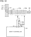
- FIG. 10 is a view to concretely explain a configuration for monitoring contactors.
- the power-supply line 103 includes lines L1, L2 and L3 corresponding to respective phases of the three-phase ACs.
- the motor 102 is connected to the power-supply line 103 through an a-contact 112a of the contactor 112, an a-contact 113a of the contactor 113, and a circuit breaker 105.
- the safety controller 110 is provided with a FB output terminal 121 and a FB input terminal 122.
- FB represents feedback.
- a b-contact 112b of the contactor 112 and a b-contact 113b of the contactor 113 are connected in series to each other between the FB output terminal 121 and the FB input terminal 122.
- the emergency stop switch 111 is omitted in FIG. 10 , in order to concentrate on describing the configuration of the contactors 112 and 113.
- a-contact refers to a contact that is opened when no current flows through the exciting coil, but is closed when a current flows therethrough.
- b-contact refers to a contact that is closed when no current flows through the exciting coil, but is opened when a current flows therethrough.
- a-contacts 112a and 113a of the contactors 112 and 113 directly operate distribution of a current to a hazard source (corresponding to, for example, the motor 102 of FIG. 11 ).
- a FB input represents a signal to be inputted to the safety controller 110.
- This FB input is inputted to the safety controller 110, so that the safety controller 110 can confirm that the a-contacts 112a and 113a of the contactors 112 and 113, respectively, are normally operating without welding failure. If the a-contact of any of the contactors 112 and 113 is welded, the safety controller 110 cannot cut off a current to the motor 102. Accordingly, it is necessary to detect the failure, such as the welding, of the a-contacts 112a and 113a of the contactors 112 and 113, respectively.
- contactors having a mechanical restriction in which the a-contact and the b-contact operate in relation to each other is used for each of the contactors 112 and 113.
- the b-contact is opened whenever the a-contact is closed, whereas the b-contact is closed whenever the a-contact is opened.
- the b-contacts 112b and 113b of the contactors 112 and 113, respectively, are connected in series to the FB input terminal 122 of the safety controller 110.
- the safety controller 110 outputs a safety output, which is a signal for permitting the operation of the contactors 112 and 113.
- the a-contacts 112a and 113a of the contactors 112 and 113, respectively, are closed in response to this safety output.
- the safety controller 110 Before outputting a safety output to the contactors 112 and 113, the safety controller 110 confirms that a feedback loop created by the b-contacts 112b and 113b of the contactors 112 and 113, respectively, has been closed. This operation corresponds to a FB monitor performed by the safety controller 110. If it is confirmed that the feedback loop has not been closed, or has been opened, the safety controller 110 does not turn on the safety output.
- a b-contact in the contactor is forcibly opened. This causes the feedback loop to be opened, so that the user can be aware of the failure.
- the reason why two contactors are provided is, when the welding of an a-contact is detected in one contactor, to cause the a-contact in the other contactor to be opened. It is believed that the possibility is low, in which both a-contacts 112a and 113a of the contactors 112 and 113, respectively, are welded. Therefore, arranging two contactors makes it possible to cut off the current to the motor 102 more reliably.
- JP 09-212206 A discloses a control device for a control route.
- This control device controls, for example, a brushless motor or a DC motor.
- JP 2003-504863 W discloses a method and system for driving a solenoid. On the basis of the difference between a desired current flow in a solenoid and an actual current flow therein, the solenoid driver controls the actual current flow in the solenoid.
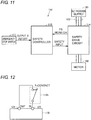
- FIG. 11 is a view illustrating another example of a configuration of a typical safety control system.
- a safety control system 152 includes a safety drive circuit 114, instead of the contactors 112 and 113.
- This safety drive circuit 114 may be, for example, a motor control apparatus, such as a servo driver, an inverter, or the like.
- a safety controller 110 monitors the FB of the safety drive circuit 114, similar to the safety control system 151 illustrated in FIG. 9 .
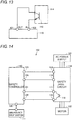
- FIG. 12 is a view to explain a feedback loop for controlling a contactor.
- FIG. 13 is a view to explain a feedback loop in a safety drive circuit.
- the b-contact of a contactor (which is exemplified by a b-contact 112b in FIG. 12 ) is connected between a FB output terminal (OUT) 121 and a FB input terminal (IN) 122 in the safety controller 110.
- the output signal from a semiconductor element 116 is used as a feedback monitor outputted from the safety drive circuit 114. The reason why a semiconductor element is used is to prolong the lifetime of the part that is responsible for a signal output function.
- the FB output terminal 121 of the safety controller 110 outputs a constant voltage (for example, DC 24 V).
- a voltage is inputted through the b-contact of the contactor or the semiconductor element. If the input voltage is at a high level, the safety controller 110 determines that the feedback loop has been closed. Otherwise, if the input voltage is at a low level, it determines that the feedback loop has been opened.
- FIG. 14 is a view to more concretely explain a connection between the safety controller and the safety drive circuit illustrated in FIG. 13 .
- the safety controller 110 includes the FB output terminal 121, the FB input terminal 122, a safety output (1) terminal 123, a safety output (2) terminal 124, and a safety input terminal 126.
- Each of the safety output (1) terminal 123 and the safety output (2) terminal 124 is a terminal that outputs a signal for permitting the operation of the safety drive circuit 114 (referred to as a "safety output").
- the safety drive circuit 114 includes a semiconductor element 116, a voltage input terminal 131, a FB monitor output terminal 132, a safety input (1) terminal 133, and a safety input (2) terminal 134.
- the semiconductor element 116 is provided between the voltage input terminal 131 and the FB monitor output terminal 132.
- Each of the safety input (1) terminal 133 and the safety input (2) terminal 134 is a terminal that inputs a safety output to the safety drive circuit 114 from the safety controller 110.
- a signal to be inputted to either of the safety input (1) terminal 133 and the safety input (2) terminal 134 is referred to as a "safety input".
- the safety output (1) terminal 123 of the safety controller 110 is connected directly to the safety input (1) terminal 133 of the safety drive circuit 114.
- the safety output (2) terminal 124 of the safety controller 110 is connected directly to the safety input (2) terminal 134 of the safety drive circuit 114.
- the FB output terminal 121 of the safety controller 110 is connected directly to the voltage input terminal 131 of the safety drive circuit 114.
- the FB input terminal 122 of the safety controller 110 is connected directly to the FB monitor output terminal 132 of the safety drive circuit 114.
- the FB output terminal 121 of the safety controller 110 outputs a signal of a high level.
- the safety controller 110 detects that a signal having been inputted to the FB input terminal 122 of the safety controller 110 is a signal of a high level.
- the safety output (1) terminal 123 and the safety output (2) terminal 124 of the safety controller 110 output respective signals of a high level.
- the reason why both of the safety output (1) terminal 123 and the safety output (2) terminal 124 in the safety controller 110 output signals of a high level is to increase the reliability of the safety output.
- both safe inputs 1 and 2 having been inputted to the safety drive circuit 114 are at a high level, the safety drive circuit 114 turns off the FB monitor output. Otherwise, if either of the safety inputs 1 and 2 is not at a high level, namely, at least one of them is at a low level, the FB monitor output is turned on.
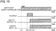
- FIG. 15 is a timing chart to explain the operation of the safety control system illustrated in FIG. 14 .
- both of the safety outputs 1 and 2 in the safety controller 110 (which will be described collectively as a "safety output 1/2" in FIG. 15 ) are at a low level.
- the safety output 1/2 is at the low level, the FB monitor output is in an "ON" state.
- the FB monitor output terminal 132 of the safety drive circuit 114 outputs a voltage.
- the input signal (safety input) that is inputted to the safety input terminal 126 of the safety controller 110 becomes a high level.
- the safety input also becomes a high level.
- the safety controller 110 detects that a signal inputted to the FB input terminal 122 has been a signal of a high level. With this, at a time t13, the safety output 1/2 of the safety controller 110 becomes a high level. Accordingly, the safety input 1/2 of the safety drive circuit 114 also becomes a high level. Once the safety input 1/2 becomes the high level, the safety drive circuit 114 turns off the semiconductor element 116. As a result, at a time t14, the FB monitor output is turned off.
- the semiconductor element 116 causes a voltage drop in the feedback loop of the safety drive circuit.
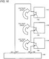
- individual semiconductor elements 116 of the safety drive circuits 114 are directly connected in series to the feedback input terminal of the safety controller 110, as illustrated in FIG. 16 .
- This configuration causes the remarkable voltage drop in the feedback loop of the safety controller 110, so that an input voltage at the FB input terminal 122 is greatly reduced.
- the safety controller 110 may determine that the feedback loop has been opened. In this case, the safety controller 110 does not turn on the safety output. As a result, it may be impossible for the safety controller 110 to permit the operations of the safety drive circuits 114 even when the safety drive circuits 114 can normally operate. In order to prevent such a great voltage drop from arising in the feedback loop, a configuration has been employed so far, in which only a limited number of safety drive circuits 114 are connected to a safety controller 110.
- JP 09-212206 A mentions a voltage drop in a servo driver (see the paragraph "0043" in the specification of JP 09-212206 A ), but lacks the description about the above disadvantage.
- JP 2003-504863 W does not describe this disadvantage.
- US 2008/0278875 A1 discloses a safety switching apparatus for failsafe disconnection of an electrical load that has a first and a second connecting terminal for connecting a first signaling switch and a third and a fourth connecting terminal for connecting a second signaling switch. It also has a first and a second output switching element, which are designed to produce a redundant output switching signal.
- the first connecting terminal is connected to a first potential and the third connecting terminal is connected to a second potential. The potentials differ from one another.
- the second connecting terminal is coupled to the first switching element in such a way that the first switching element receives the first potential via the first signaling switch.
- the fourth connecting terminal is coupled to the second switching element in such a way that the second switching element receives the second potential via the second signaling switch.
- a circuit arrangement may be provided for determining at least one further potential at the second and/or fourth connecting terminal, and said circuit arrangement may be designed to control the redundant output switching signal as a function of the further potential.
- US 7,116,069 B1 discloses that a rapid connection of multiple motor drive modules for safety operation may be made using screw terminals for initial connections to a safety controller and pre-wired cables for daisy chaining subsequent motor drives responsive to the same safety signals.
- Adaptor modules may be used to provide for a variety of different connector configurations depending on the location of the motor drive within the signal chain.
- An object of the present invention is to provide a safety control system that is capable of monitoring many more drive circuits by using a single controller without modifying the configurations of the controller and the drive circuits.
- a safety control system comprising a controller and at least one drive circuit according to claim 1.
- the controller further includes an auxiliary output terminal through which the controller outputs an auxiliary output signal that is synchronized with the output signal. After confirming that the feedback loop has been closed, the controller outputs the output signal and the auxiliary output signal through the signal output terminal and the auxiliary output terminal, respectively.
- the safety control system further includes a second relay.
- the second relay includes: a second coil; and a third contact which is opened when a current flows through the second coil but is closed when no current flows through the second coil.
- the first coil of the first relay and the third contact of the second relay are electrically connected in series to one another between the monitor output terminal of the drive circuit and the ground.
- the second coil of the second relay is electrically connected to the auxiliary output terminal of the controller and the ground.
- the at least one drive circuit includes a plurality of drive circuits.
- the at least one first relay includes a plurality of first relays provided corresponding to the plurality of drive circuits.
- the respective first contacts of the plurality of the first relays are electrically connected in series to one another between the feedback output terminal and the feedback input terminal of the controller.
- Each of the second contacts of the plurality of the first relays is electrically connected to the signal output terminal of the controller and the signal input terminal of one of the plurality of drive circuits which corresponds to each first relay.
- the respective first coils of the plurality of the first relays are electrically connected to the monitor output terminals of the corresponding drive circuits, and are connected in parallel to the third contact of the second relay.
- each of the first coils of the first relays prefferably be electrically connected to the ground and the monitor output terminal of a corresponding one of the drive circuits.
- the at least one drive circuit includes a plurality of drive circuits.
- the at least one first relay includes a plurality of first relays provided corresponding to the plurality of drive circuits.
- the respective first contacts of the plurality of the first relays are electrically connected in series to one another between the feedback output terminal and the feedback input terminal of the controller.
- the second contacts of the plurality of the first relays are electrically connected in series to one another, and each second contact is electrically connected to the signal output terminal of the controller and the signal input terminal of one of the drive circuits which corresponds to each first relay.
- FIG. 1 is a view illustrating an example of a configuration of a safety control system according to a first embodiment of the present invention.
- a safety control system 51 includes a safety controller 10, an input apparatus 11, a safety drive circuit 14, and relays 17 and 18.
- the input apparatus 11 is, for example, an emergency stop switch, but instead, it may be any other device having a function of inputting a signal to the safety controller 10 in accordance with a user's operation. For example, a light curtain or a door switch may be applied to the input apparatus 11.
- the input apparatus 11 is not limited to a single unit, but may be implemented by a combination of multiple units.
- a motor 2 serves as a power source, and operates by being supplied with three-phase ACs from an AC power supply 1.
- the motor 2 is driven by the safety drive circuit 14.
- the safety drive circuit 14 supplies drive electricity to the motor 2 from the AC power supply 1, and cuts off the electricity thereto.
- the safety drive circuit 14 may be a motor control apparatus, such as a servo driver, an inverter, or the like.
- the safety controller 10 has a function of monitoring the safety drive circuit 14. Note that the AC power supply 1 may be replaced by a DC power supply.
- safety controller and "safety drive circuit” are used. However, note that any of the “safety controller” and “safety drive circuit” does not represent any special device.
- the present invention is applicable to any given control device (controller) and driving device (drive circuit or driver), as long as they conform to predetermined safety specifications.
- the safety controller 10 includes a FB (feedback) output terminal 21, a FB input terminal 22, a safety output (1) terminal 23, a safety output (2) terminal 24, an auxiliary output terminal 25, and a safety input terminal 26.
- the FB output terminal 21 and the FB input terminal 22 are terminals that create a feedback loop through which the safety controller 10 monitors the state of the safety drive circuit 14.
- the expression "the state of the safety drive circuit 14" refers to a state where the output is permitted or cut off (for example, see FIG. 2 ).
- Each of the safety output (1) terminal 23 and the safety output (2) terminal 24 is a terminal, through which the safety controller 10 outputs a signal (referred to as a "safety output”) for permitting an operation of the safety drive circuit 14.
- the auxiliary output terminal 25 is a terminal, through which the safety controller 10 outputs a signal (referred to as an "auxiliary output") that is synchronized with the safety output.
- the safety input terminal 26 is a terminal, through which a signal (referred to as a "safety input") from the input apparatus 11 is inputted to the safety controller 10.
- the input apparatus 11 is connected to the safety input terminal 26 of the safety controller 10.
- the safety drive circuit 14 includes a semiconductor element 16, a voltage input terminal 31, a FB monitor output terminal 32, a safety input (1) terminal 33, and a safety input (2) terminal 34.
- the safety input (1) terminal 33 and the safety input (2) terminal 34 are terminals, through which safety outputs that have been outputted from the safety output (1) terminal 23 and the safety output (2) terminal 24, respectively, of the safety controller 10 are inputted to the safety drive circuit 14.
- a signal that is inputted to either of the safety input (1) terminal 33 and the safety input (2) terminal 34 is called a "safety input”.
- the present invention can be applied.
- the reliability of the safety control system can be further increased.
- the semiconductor element 16 is provided between the voltage input terminal 31 and the FB monitor output terminal 32.
- the FB monitor output terminal 32 is a monitor output terminal, through which the safety drive circuit 14 outputs a monitor voltage (FB monitor) indicating the state of the safety drive circuit 14 to the safety controller 10.
- the semiconductor element 16 generates a monitor voltage to be outputted from the FB monitor output terminal 32.
- the voltage input terminal 31 is a voltage input terminal, through which a voltage for causing the semiconductor element 16 to generate a monitor voltage is inputted to the semiconductor element 16. In this embodiment, the voltage input terminal 31 is connected to a constant voltage source.
- the safety drive circuit 14 outputs a FB monitor from the FB monitor output terminal 32, before respective output signals (safety outputs) from the safety controller 10 are inputted to the safety input (1) terminal and the safety input (2) terminal of the safety drive circuit 14, as will be described in detail.
- the relay 17 includes an a-contact 17a, a b-contact 17b, and a coil 17c.
- the a-contact 17a and the b-contact 17b are mechanically restricted, such that they operate in relation to each other in a complementary manner.
- the expression "complementary manner" indicates a state where one of the a-contact 17a and the b-contact 17b is "opened” when the other is "closed". Specifically, when the a-contact 17a is closed, the b-contact 17b is opened. Meanwhile, when the a-contact 17a is opened, the b-contact 17b is closed. Accordingly, both of the a-contact 17a and the b-contact 17b are not closed at the same time. In general, such a structure is also called a "force guided contact structure". Thus, any given relay is applicable to the relay 17, as long as being equipped with the force guided contact structure.
- the a-contact 17a corresponds to a "first contact of a first relay" according to the present invention.
- the b-contact 17b corresponds to a "second contact of the first relay” according to the present invention.
- the coil 17c corresponds to a "first coil of the first relay” according to the present invention.
- the a-contact 17a is electrically connected to the FB output terminal 21 and the FB input terminal 22 of the safety controller 10.
- the b-contact 17b is electrically connected to the safety output (1) terminal 23 of the safety controller 10 and the safety input (1) terminal 33 of the safety drive circuit 14.
- An end of the coil 17c is electrically connected to the FB monitor output terminal 32 of the safety drive circuit 14.
- the expression "electrical connection” includes not only a direct connection but also a connection through, for example, a wire.
- the relay 18 includes a b-contact 18b and a coil 18c.
- One end of the b-contact 18b is connected to the other end of the coil 17c of the relay 17, whereas the other end of the b-contact 18b is grounded.
- the coil 17c of the relay 17 and the b-contact 18b of the relay 18 are connected in series to one another between the FB monitor output terminal 32 of the safety drive circuit 14 and the ground.
- One end of the coil 18c is connected to the auxiliary output terminal 25 of the safety controller 10, whereas the other end of the coil 18c is connected to the ground.
- the coil 18c is electrically connected between the auxiliary output terminal 25 of the safety controller 10 and the ground.
- the force guided contact structure is not essential, and any general-purpose relay can be given as an example thereof.
- the b-contact 18b corresponds to a "third contact of a second relay" according to the present invention
- the coil 18c corresponds to a "second coil of the second relay” according to the present invention.
- a-contact 17a of the relay 17 is provided in the feedback loop of the safety controller 10, namely, on a route between the FB output terminal 21 and the FB input terminal 22 of the safety controller 10.
- the resistance of the a-contact 17a is much smaller than the ON-resistance of the semiconductor element 16. Accordingly, there is no substantial factor in a voltage drop across the above feedback loop.
- the relay 18 is driven by the auxiliary output that is synchronized with the safety output of the safety controller 10.
- the relay 17 is driven by the b-contact 18b of the relay 18 and the semiconductor element 16 of the safety drive circuit 14 (namely, the FB monitor output of the safety drive circuit 14).
- the b-contact 17b of the relay 17 may be provided between the safety output (2) terminal 24 of the safety controller 10 and the safety input (2) terminal 34 of the safety drive circuit 14.
- a b-contact of another relay equipped with the force guided contact structure may be provided between the safety output (2) terminal 24 of the safety controller 10 and the safety input (2) terminal 34 of the safety drive circuit 14.
- FIG. 2 is a view to explain an operation of the safety drive circuit illustrated in FIG. 1 .
- a "safety input 1" and a “safety input 2" represent signals to be inputted to the safety input (1) terminal 33 and the safety input (2) terminal 34, respectively, of the safety drive circuit 14. If both safety inputs 1 and 2 for the safety drive circuit 14 are at a high level, the output of the safety drive circuit 14 is permitted. In this case, the FB monitor output is turned off. Otherwise, if either of the safety inputs 1 and 2 for the safety drive circuit 14 is not at a high level, namely, if at least one of them is at a low level, the output of the safety drive circuit 14 is cut off. In this case, the FB monitor output is turned on.
- the output of the safety drive circuit 14 may be, for example, electricity supplied to the motor 2 from the safety drive circuit 14.
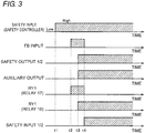
- FIG. 3 is a timing chart to explain an operation of the safety control system illustrated in FIG. 1 .
- the safety output 1 and the safety output 2 of the safety controller 10 (which are described collectively as a "safety output 1/2" in FIG. 3 ) are both at a low level.
- the safety output 1/2 is at the low level, the FB monitor output is in an ON state.
- the semiconductor element 16 is in an ON state, and the FB monitor output terminal 32 outputs a monitor voltage.
- a signal which is inputted to the safety input terminal 26 of the safety controller 10 from the input apparatus 11 becomes a high level.
- the safety input in response to a user's operation with the input apparatus, the safety input becomes a high level.
- the expression "a signal becomes a high level” means that a signal is being output. This will apply to the following description.
- a-contact 17a of the relay 17 is closed.
- the feedback loop is closed.
- a signal (FB input) that is inputted to the FB input terminal 22 of the safety controller 10 becomes a high level.
- This FB input of the high level causes the safety output 1/2 of the safety controller 10 to become a high level at a time t3.
- the auxiliary output becomes a high level in synchronization with the safety output 1/2.
- This auxiliary output becoming the high level causes a current to flow through the coil 18c of the relay 18. Following this, the relay 18 is turned on.
- the turn-on of the relay 18 causes the b-contact 18b to be opened.
- the turn-off of the relay 17 causes the a-contact 17a and the b-contact 17b to be opened and closed, respectively. Therefore, the safety input 1/2 that is inputted to the safety drive circuit 14 becomes a high level.
- This safety input 1/2 of the high level causes the semiconductor element 16 of the safety drive circuit 14 to be turned off. As a result, the FB monitor output is turned off.
- the operation of the safety control system according to this embodiment is basically the same as that of a typical safety control system. Specifically, after the FB input becomes a high level, the safety output 1/2 becomes a high level. The safety output 1/2 of the high level causes the safety input 1/2 to become a high level. Therefore, it is possible to apply an existing safety controller and safety drive circuit to the safety control system according to this embodiment.
- the safety controller 10 there is no factor in a voltage drop across the FB loop created by the safety controller 10. Accordingly, in the case where a plurality of safety drive circuits are connected to a single safety controller, the amount of the voltage drop arising in the FB loop is smaller than that in a typical configuration (see FIG. 16 ). This enables many more safety drive circuits to be connected to a single safety controller, in comparison with a typical configuration. Consequently, it is possible to increase the number of safety drive circuits which a single safety controller can monitor.
- FIG. 4 is a view illustrating a configuration of a safety control system according to the first embodiment, in which a plurality of safety drive circuits are connected to a single safety controller.
- the safety control system 52 differs from the safety control system 51 in further including a safety drive circuit 14A and a relay 19.
- the safety drive circuit 14A is configured to supply AC electricity to a motor 2A from an AC power supply 1A, or to cut off the AC electricity thereto. Note that in FIG. 4 , the AC power supplies 1 and 1A are illustrated, but instead, a single AC power supply may supply AC electricity to the motors 2 and 2A.
- the relay 19 includes an a-contact 19a, a b-contact 19b, and a coil 19c. Similar to the relay 17, the a-contact 19a and the b-contact 19b are mechanically restricted, such that they operate in relation to each other.
- the safety drive circuit 14A has a configuration that is the same as that of the safety drive circuit 14.
- the safety drive circuit 14A includes a semiconductor element 16A, a voltage input terminal 31A, a FB monitor output terminal 32A, a safety input (1) terminal 33A, and a safety input (2) terminal 34A.
- the a-contact 17a of the relay 17 and the a-contact 19a of the relay 19 are electrically connected in series to one another between the FB output terminal 21 and the FB input terminal 22 of the safety controller 10.
- the safety input (1) terminal 33A is connected to the b-contact 17b of the relay 17, together with the safety input (1) terminal 33 of the safety drive circuit 14.
- the safety input (2) terminal 34A is connected to the b-contact 19b of the relay 19, together with the safety input (2) terminal 34 of the safety drive circuit 14.
- the b-contact 17b of the relay 17 is electrically connected between a signal output terminal (or the safety output (1) terminal 23) of the safety controller 10 and a signal input terminal (or the safety input (1) terminal 33) of the safety drive circuit 14 which corresponds to the relay 17.
- the b-contact 19b of the relay 19 is electrically connected between a signal output terminal (or the safety output (2) terminal 24) of the safety controller 10 and a signal input terminal (or the safety input (2) terminal 34A) of the safety drive circuit 14A which corresponds to the relay 19.
- the b-contact 19b of the relay 19 may be inserted into a route that electrically connects the safety input (1) terminal 33 to the safety input (1) terminal 33A.
- One end of the coil 19c is connected to the FB monitor output terminal 32A of the safety drive circuit 14A, whereas the other end of the coil 19c is connected to the b-contact 18b of the relay 18. Accordingly, the coils 17c and 19c are connected in parallel to the b-contact 18b of the relay 18.
- the operation of the safety control system 52 illustrated in FIG. 4 is basically the same as that illustrated in FIG. 3 .
- the single safety controller 10 can also monitor three or more safety drive circuits in this embodiment. Relays (in which each pair of the a-contacts and the b-contacts are configured to operate in relation to each other in a mechanical manner), the number of which is the same as the number of the safety drive circuits, are provided, and the a-contacts of these relays are electrically connected in series between the FB output terminal 21 and the FB input terminal 22 of the safety controller 10.
- the b-contacts of the relays are electrically connected between a signal input terminal (or one of a safety input (1) terminal and a safety input (2) terminal) of a corresponding safety drive circuit and a signal output terminal (or a corresponding one of the safety output (1) terminal 23 and safety input (2) terminal 24) of the safety controller 10.
- the coils of the above relays are connected in parallel to the b-contact 18b of the relay 18.
- a single safety controller can monitor and control much more safety drive circuits than those in a typical configuration.
- a configuration in which a single safety controller monitors many more safety drive circuits can be simply constructed at a low cost.
- the relays 17 and 19 are used, each of which is mechanically restricted such that the a-contact and the b-contact operate in relation to each other.
- the a-contact of each relay is provided between the FB output terminal 21 and the FB input terminal 22 of the safety controller 10.
- the b-contact of each relay is provided between a safety output terminal of the safety controller 10 and a safety input terminal of a corresponding safety drive circuit.
- the FB monitor is basically used to find out the welding of the a-contacts 112a and 113a in the contactors 112 and 113, respectively. Moreover, when the drive output of the safety drive circuit 114 fails, the FB monitor output is maintained in an OFF state, thus preventing the safety output of the safety controller 110 from being maintained in an ON state and avoiding the dangerous condition. If the failure, such as the welding, of the a-contacts 112a and 113a cannot be detected, the safety output of the safety controller 110 may be turned on even when the FB monitor output is maintained in an OFF state.
- the b-contact 17b of the relay 17 (or the b-contact 19b of the relay 19) is forcibly opened when the a-contact 17a of the relay 17 (or the a-contact 19a of the relay 19) is welded.
- at least one of the safety inputs in the safety drive circuit (14 or 14A) is turned off.
- the safety drive circuit (14 or 14A) does not operate, so that the power source (or the motor 2) does not operate, either.
- the relay 18 may be a general-purpose relay.
- the possible failure of the relay 18 can be an ON or OFF failure.
- the output of the safety drive circuit 14 (or 14A) is cut off, even when any of an ON and OFF failures occurs.
- the relay 18 is kept OFF.
- the relay 17 (or 19) is maintained in an OFF state, whereas the a-contact (17a or 19a) of the relay 17 (or 19) is maintained being opened.
- the FB loop created by the safety controller 10 is opened.
- the safety outputs 1 and 2 of the safety controller 10 become a low level. Consequently, the outputs of the safety drive circuits (14 and 14A) are cut off.
- FIG. 5 is a view illustrating an example of a configuration of a safety control system according to a second embodiment of the present invention.
- a safety control system 53 according to the second embodiment is different from the safety control system 51 according to the first embodiment, in that the relay 18 is omitted.
- the safety controller 10 may be provided with the auxiliary output terminal 25, similar to the first embodiment, but this auxiliary output terminal 25 may be an option in the second embodiment. Therefore, the auxiliary output terminal 25 is not illustrated in FIG. 5 .
- One end of the coil 17c in the relay 17 is connected to the FB monitor output terminal 32 of the safety drive circuit 14. The other end of the coil 17c is grounded. Thus, in this embodiment, the coil 17c is electrically connected between the FB monitor output terminal 32 of the safety drive circuit 14 and the ground.
- the other part of the configuration which the safety control system 53 according to the second embodiment has is the same as corresponding part of the configuration which the safety control system 51 according to first embodiment has. Accordingly, the subsequent explanation will be skipped.
- FIG. 6 is a view to explain an operation of the safety drive circuit illustrated in FIG. 5 .
- the FB monitor output is turned off.
- the second embodiment differs from the first embodiment.
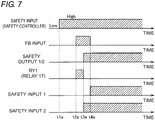
- FIG. 7 is a timing chart to explain an operation of the safety control system illustrated in FIG. 5 .
- the safety output 1 and the safety output 2 of the safety controller 10 (which are described collectively as a "safety output 1/2" in FIG. 7 ) are both at a low level.
- the safety output 1/2 is at the low level, the FB monitor output is in an ON state.
- a safety input which is inputted to the safety input terminal 26 of the safety controller 10 becomes a high level.
- the a-contact 17a of the relay 17 is closed. Accordingly, a signal (FB input) that is inputted to the FB input terminal 22 of the safety controller 10 becomes a high level.
- This FB input becoming the high level causes the safety output 1/2 of the safety controller 10 to become a high level at a time t3a.
- the b-contact 17b of the relay 17 is opened. Accordingly, the safety input 1 of the safety drive circuit 14 is at a low level at the time t3a. Meanwhile, the safety input 2 of the safety drive circuit 14 is at a high level.
- the safety inputs 1 and 2 becoming the low and high levels, respectively, in the safety drive circuit 14 cause the FB monitor output of the safety drive circuit 14 to be turned off. As a result, no current flows through the coil 17c of the relay 17, so that the relay 17 is turned off.
- the a-contact 17a of the relay 17 is opened but the b-contact 17b thereof is closed.
- the safety input 1 which is inputted to the safety drive circuit 14 becomes a high level.
- the safety inputs 1 and 2 are kept at the high level.
- the FB monitor output is at a low level.
- the FB monitor output is kept at the low level even after the time t4a.
- FIG. 8 is a view illustrating a configuration of a safety control system according to the second embodiment, in which a plurality of safety drive circuits are connected to a single safety controller.
- a safety control system 54 differs from the safety control system 53 in further including the safety drive circuit 14A and the relay 19. Note that because the configuration of the safety drive circuit 14A is the same as that illustrated in FIG. 4 , the subsequent description will be skipped. Likewise, because the configuration of the relay 19 is the same as that illustrated in FIG. 4 , the subsequent description will be skipped.
- the b-contact 17b of the relay 17 and the b-contact 19b of the relay 19 are connected in series to one another between the safety output (1) terminal 23 of the safety controller 10 and the safety input (1) terminal (33 or 33A) of the safety drive circuit (14 or 14A).
- the coil 19c of the relay 19 is electrically connected to the FB monitor output terminal 32A of the safety drive circuit 14A and the ground. Note that in the configuration illustrated in FIG. 8 , the coil 17c of the relay 17 and the coil 19c of the relay 19 are connected to the ground together, but may be connected to the ground separately.
- the configuration according to the second embodiment can make the relay 18 unnecessary, even when a plurality of safety drive circuits are connected to a single safety controller.
- the b-contact 17b of the relay 17 and the b-contact 19b of the relay 19 may be connected in series to one another between the safety output (2) terminal 24 of the safety controller 10 and the safety input (2) terminal (34 or 34A) of the safety drive circuit (14 or 14A).
- the safety drive circuits (14 and 14A) operate in accordance with the relationship illustrated in FIG. 7 . Accordingly, it is necessary to connect one of the two safety input terminals in each of the safety drive circuits (14 and 14A) to a corresponding safety output terminal of the safety controller 10 without a b-contact therebetween, namely, directly.
- the second embodiment can produce the same effect as the first embodiment does.
- a configuration in which a single safety controller monitors many more safety drive circuits can be simply constructed at a low cost.
- the second embodiment can decrease the number of relays used therein, in comparison with the first embodiment.
Landscapes
- Physics & Mathematics (AREA)
- General Physics & Mathematics (AREA)
- Engineering & Computer Science (AREA)
- Automation & Control Theory (AREA)
- Safety Devices In Control Systems (AREA)
Claims (4)
- Système de commande de sécurité (51, 52) comprenant :un contrôleur (10) ; etau moins un circuit d'attaque (14, 14A) configuré pour attaquer une source d'énergie (2, 2A) ;le contrôleur (10) comprenant :une borne de sortie de rétroaction (21) et une borne d'entrée de rétroaction (22) qui créent une boucle de rétroaction qui permet au contrôleur (10) de surveiller un état dudit au moins un circuit d'attaque (14, 14A) ; etune borne de sortie de signal (23) par l'intermédiaire de laquelle le contrôleur (10) délivre un signal de sortie pour permettre audit au moins un circuit d'attaque (14, 14A) d'attaquer la source d'énergie (2, 2A) ;une borne de sortie auxiliaire (25) par l'intermédiaire de laquelle le contrôleur (10) délivre un signal de sortie auxiliaire qui est synchronisé avec le signal de sortie ;le circuit d'attaque (14, 14A) comprenant :une borne d'entrée de signal (33, 33A) par l'intermédiaire de laquelle le signal de sortie délivré par la borne de sortie de signal (23) du contrôleur (10) est appliqué au circuit d'attaque (14, 14A) ;une borne de sortie de moniteur (32, 32A) par l'intermédiaire de laquelle le circuit d'attaque (14, 14A) délivre une tension de surveillance indiquant l'état du circuit d'attaque (14, 14A) à partir du circuit d'attaque (14, 14A) au contrôleur (10) ;un élément semi-conducteur (16, 16A) qui génère la tension de surveillance à délivrer par l'intermédiaire de la borne de sortie de moniteur (32, 32A) ; etune borne d'entrée de tension (31, 31A) par l'intermédiaire de laquelle une tension pour amener l'élément semi-conducteur (16, 16A) à générer la tension de surveillance est appliquée à l'élément semi-conducteur (16, 16A) ;dans lequel le circuit d'attaque (14, 14A) délivre la tension de surveillance par l'intermédiaire de la borne de sortie de moniteur (32, 32A) avant que le signal de sortie du contrôleur (10) ne soit appliqué à la borne d'entrée de signal (33, 33A),dans lequel le système de commande de sécurité (51, 52) comprend en outre :au moins un premier relais (17, 19) qui comprend une première bobine (17c, 19c), et un premier contact (17a, 19a) et un second contact (17b, 19b) qui sont tous deux actionnés l'un par rapport à l'autre d'une manière complémentaire, le premier relais (17, 19) fermant le premier contact (17a, 19a) et ouvrant le second contact (17b, 19b) quand un courant circule dans la première bobine (17c, 19c), le premier relais (17, 19) ouvrant le premier contact (17a, 19a) et fermant le second contact (17b, 19b) quand aucun courant ne circule dans la première bobine (17c, 19c), etun second relais (18) comprenant une seconde bobine (18c), et un troisième contact (18b) qui est ouvert lorsqu'un courant circule dans la seconde bobine (18c), mais est fermé quand aucun courant ne circule dans la seconde bobine (18c),dans lequel le premier contact (17a, 19a) du premier relais (17, 19) est connecté électriquement à la borne de sortie de rétroaction (21) et à la borne d'entrée de rétroaction (22) du contrôleur (10),dans lequel le second contact (17b, 19b) du premier relais (17, 19) est connecté électriquement à la borne de sortie de signal (23) du contrôleur (10) et à la borne d'entrée de signal (33, 33A) du circuit d'attaque (14, 14A),dans lequel la première bobine (17c, 19c) du premier relais (17, 19) est connectée électriquement à la borne de sortie de moniteur (32, 32A) du circuit d'attaque (14, 14A), etdans lequel la première bobine (17c, 19c) du premier relais (17, 19) et le troisième contact (18b) du second relais (18) sont connectés électriquement en série l'un à l'autre entre la borne de sortie de moniteur (32, 32A) du circuit d'attaque (14, 14A) et la masse, et la seconde bobine (18c) du second relais (18) est connectée électriquement à la borne de sortie auxiliaire (25) du contrôleur (10) et à la masse.
- Système de commande de sécurité (51, 52) selon la revendication 1, dans lequel
après avoir confirmé que la boucle de rétroaction a été fermée, le contrôleur (10) délivre le signal de sortie et le signal de sortie auxiliaire par l'intermédiaire de la borne de sortie de signal (23) et de la borne de sortie auxiliaire (25), respectivement. - Système de commande de sécurité (51, 52) selon la revendication 1 ou la revendication 2, dans lequel ledit au moins un circuit d'attaque (14, 14A) comprend une pluralité de circuits d'attaque (14, 14A),
ledit au moins un premier relais (17, 19) comprend une pluralité de premiers relais (17, 19) prévus en correspondance avec la pluralité de circuits d'attaque (14, 14A),
les premiers contacts respectifs (17a, 19a) de la pluralité des premiers relais (17, 19) sont connectés électriquement en série entre la borne de sortie de rétroaction (21) et la borne d'entrée de rétroaction (22) du contrôleur,
chacun des seconds contacts (17b, 19b) de la pluralité des premiers relais (17, 19) est connecté électriquement à la borne de sortie de signal (23) du contrôleur (10) et à la borne d'entrée de signal (33, 33A) de l'un de la pluralité de circuits d'attaque (14, 14A) qui correspond à chaque premier relais (17, 19), et
les premières bobines respectives (17c, 19c) de la pluralité des premiers relais (17, 19) sont connectées électriquement aux bornes de sortie de moniteur (32, 32A) des circuits d'attaque correspondants (14, 14A), et sont connectées en parallèle au troisième contact (18b) du second relais (18). - Système de commande de sécurité (51, 52) selon la revendication 1 ou la revendication 2, dans lequel ledit au moins un circuit d'attaque (14, 14A) comprend une pluralité de circuits d'attaque (14, 14A),
ledit au moins un premier relais (17, 19) comprend une pluralité de premiers relais (17, 19) prévus en correspondance avec la pluralité de circuits d'attaque (14, 14A),
les premiers contacts respectifs (17a, 19a) de la pluralité des premiers relais (17, 19) sont connectés électriquement en série les uns aux autres entre la borne de sortie de rétroaction (21) et la borne d'entrée de rétroaction (22) du contrôleur (10), et
les seconds contacts (17b, 19b) de la pluralité des premiers relais (17, 19) sont connectés électriquement en série les uns aux autres, et chaque second contact (17b, 19b) est connecté électriquement à la borne de sortie de signal (23) du contrôleur (10) et à la borne d'entrée de signal (33, 33A) de l'un des circuits d'attaque (14, 14A) qui correspond à chaque premier relais (17, 19).
Applications Claiming Priority (1)
| Application Number | Priority Date | Filing Date | Title |
|---|---|---|---|
| JP2011244306A JP5794116B2 (ja) | 2011-11-08 | 2011-11-08 | 安全制御システム |
Publications (3)
| Publication Number | Publication Date |
|---|---|
| EP2592502A2 EP2592502A2 (fr) | 2013-05-15 |
| EP2592502A3 EP2592502A3 (fr) | 2015-11-11 |
| EP2592502B1 true EP2592502B1 (fr) | 2018-01-24 |
Family
ID=47355806
Family Applications (1)
| Application Number | Title | Priority Date | Filing Date |
|---|---|---|---|
| EP12188869.7A Active EP2592502B1 (fr) | 2011-11-08 | 2012-10-17 | Système de contrôle de sécurité |
Country Status (4)
| Country | Link |
|---|---|
| US (1) | US9329581B2 (fr) |
| EP (1) | EP2592502B1 (fr) |
| JP (1) | JP5794116B2 (fr) |
| CN (1) | CN103092092B (fr) |
Families Citing this family (8)
| Publication number | Priority date | Publication date | Assignee | Title |
|---|---|---|---|---|
| TWI581484B (zh) * | 2014-12-31 | 2017-05-01 | 財團法人工業技術研究院 | 電池電極漿料組成物 |
| JP6479719B2 (ja) | 2015-08-19 | 2019-03-06 | 株式会社東芝 | 点検システム |
| JP2018137881A (ja) | 2017-02-21 | 2018-08-30 | オムロン株式会社 | モータ制御装置およびモータ制御システム |
| JP6772887B2 (ja) * | 2017-02-21 | 2020-10-21 | オムロン株式会社 | サーボシステム |
| WO2019208491A1 (fr) * | 2018-04-27 | 2019-10-31 | Smc株式会社 | Système de soupape électromagnétique |
| JP2020160866A (ja) | 2019-03-27 | 2020-10-01 | Idec株式会社 | 安全機器 |
| CN113410908B (zh) * | 2021-06-18 | 2022-07-26 | 卡斯柯信号有限公司 | 支持主备同驱的单线圈继电器的驱动接口系统 |
| CN114884173A (zh) | 2022-06-06 | 2022-08-09 | 东莞市航车宝未来科技有限公司 | 一种安全控制电路及设有该电路的汽车应急启动夹 |
Citations (1)
| Publication number | Priority date | Publication date | Assignee | Title |
|---|---|---|---|---|
| US7116069B1 (en) * | 2005-04-22 | 2006-10-03 | Rockwell Automation Technologies, Inc. | Rapid configuration safety motor drive kit |
Family Cites Families (19)
| Publication number | Priority date | Publication date | Assignee | Title |
|---|---|---|---|---|
| DE19602454C2 (de) | 1996-01-24 | 2001-04-12 | Agie Sa | Verfahren und Fuzzy-Regler zum Abstimmen der Reglerparameter eines Reglers |
| JP3668632B2 (ja) * | 1999-03-03 | 2005-07-06 | 東日本旅客鉄道株式会社 | 鉄道用保安制御装置及び保安制御システム |
| DE10011076A1 (de) * | 1999-03-10 | 2000-09-14 | Dold & Soehne Kg E | Not-Aus-Vorrichtung |
| US6633786B1 (en) * | 1999-05-07 | 2003-10-14 | Mark M. Majors | Irrigation safety control system |
| US6404612B1 (en) | 1999-07-10 | 2002-06-11 | Mykrolis Corporation | Method for system for driving a solenoid |
| DE19962497A1 (de) * | 1999-12-23 | 2001-07-05 | Pilz Gmbh & Co | Schaltungsanordnung zum sicheren Abschalten einer Anlage, insbesondere einer Maschinenanlage |
| DE10016712C5 (de) * | 2000-04-04 | 2004-09-16 | Pilz Gmbh & Co. | Sicherheitsschaltgerät und Verfahren zur Einstellung einer Betriebsart eines Sicherheitsschaltgeräts |
| JP2003140702A (ja) * | 2001-11-01 | 2003-05-16 | Japan Control Engineering Co Ltd | セーフティリレーユニットの状態モニタ装置 |
| US7610119B2 (en) * | 2003-07-08 | 2009-10-27 | Omron Corporation | Safety controller and system using same |
| JP4238705B2 (ja) * | 2003-11-25 | 2009-03-18 | オムロン株式会社 | セーフティコントローラ |
| WO2005096465A1 (fr) * | 2004-04-01 | 2005-10-13 | System Consult Pty Ltd | Module de commutation de securite |
| DE502005009527D1 (de) * | 2004-04-19 | 2010-06-17 | Pilz Gmbh & Co Kg | Meldegerät für eine sicherheitsschaltung |
| DE102005014125A1 (de) * | 2005-03-22 | 2006-09-28 | Pilz Gmbh & Co. Kg | Sicherheitsschaltvorrichtung zum sicheren Abschalten eines elektrischen Verbrauchers |
| EP1911058B1 (fr) * | 2005-08-02 | 2008-12-03 | Phoenix Contact GmbH & Co. KG | Commutateur de securite pour commander un dispositif relevant de la securite, afin de le mettre dans un etat de securite |
| DE102005055325C5 (de) * | 2005-11-11 | 2013-08-08 | Pilz Gmbh & Co. Kg | Sicherheitsschaltvorrichtung zum fehlersicheren Abschalten eines elektrischen Verbrauchers |
| DE102006010106A1 (de) * | 2006-03-01 | 2007-09-06 | Pilz Gmbh & Co. Kg | Sicherheitsschaltvorrichtung zum fehlersicheren Abschalten eines elektrischen Verbrauchers |
| DE102007037767A1 (de) * | 2007-02-26 | 2008-08-28 | Diehl Ako Stiftung & Co. Kg | Gerät mit ansteuerbarer Schutzeinrichtung |
| JP2011165058A (ja) * | 2010-02-12 | 2011-08-25 | Jtekt Corp | 安全制御盤及び安全制御システム |
| JP5367623B2 (ja) * | 2010-03-15 | 2013-12-11 | オムロン株式会社 | サーボシステム、サーボモータ駆動装置、セーフティユニットおよびサーボシステムの制御方法 |
-
2011
- 2011-11-08 JP JP2011244306A patent/JP5794116B2/ja active Active
-
2012
- 2012-10-17 EP EP12188869.7A patent/EP2592502B1/fr active Active
- 2012-10-22 US US13/656,992 patent/US9329581B2/en active Active
- 2012-10-25 CN CN201210413095.0A patent/CN103092092B/zh active Active
Patent Citations (1)
| Publication number | Priority date | Publication date | Assignee | Title |
|---|---|---|---|---|
| US7116069B1 (en) * | 2005-04-22 | 2006-10-03 | Rockwell Automation Technologies, Inc. | Rapid configuration safety motor drive kit |
Also Published As
| Publication number | Publication date |
|---|---|
| US20130113301A1 (en) | 2013-05-09 |
| JP2013101459A (ja) | 2013-05-23 |
| US9329581B2 (en) | 2016-05-03 |
| EP2592502A3 (fr) | 2015-11-11 |
| EP2592502A2 (fr) | 2013-05-15 |
| CN103092092A (zh) | 2013-05-08 |
| CN103092092B (zh) | 2015-06-03 |
| JP5794116B2 (ja) | 2015-10-14 |
Similar Documents
| Publication | Publication Date | Title |
|---|---|---|
| EP2592502B1 (fr) | Système de contrôle de sécurité | |
| US10460895B2 (en) | Safety switching device for fail-safely disconnecting an electrical load | |
| EP3396811A1 (fr) | Appareil d'alimentation électrique auxiliaire d'élément automoteur | |
| WO2016038683A1 (fr) | Dispositif inverseur pour entraîner un moteur à courant alternatif polyphasé | |
| US11695269B2 (en) | Electrical AC/DC conversion arrangement | |
| KR102413474B1 (ko) | 진단 장치 | |
| JP5615470B1 (ja) | 電力供給制御装置、及びプログラマブルロジックコントローラ | |
| CN109247058B (zh) | 具有多系统电路的电子控制装置 | |
| CN106687351B (zh) | 具有安全功能的输送设备 | |
| EP3419163B1 (fr) | Appareil de détection | |
| CN110582431B (zh) | 用于商用车的电流供给单元和用于运行商用车的电流供给单元的方法 | |
| KR20200134976A (ko) | 배터리 시스템 및 이의 릴레이 제어 장치 | |
| EP3425654A1 (fr) | Dispositif de relais | |
| US20160087571A1 (en) | Circuit arrangement having redundant half bridges for operating an electric machine | |
| WO2016042803A1 (fr) | Commutateur | |
| KR101304786B1 (ko) | 모터스타터 제어방법 및 이를 이용한 모터스타터 | |
| KR20200081477A (ko) | 브레이크 구동 제어 회로와 그 고장 검출 방법 | |
| JP7353357B2 (ja) | 電源供給装置及び電源供給システム | |
| KR20100134632A (ko) | 로드 피더의 연결 단자들에 연결하기 위한 연결 디바이스들을 갖는 제어 모듈 및 로드 피더 | |
| KR101297120B1 (ko) | 모니터링 회로가 자동적으로 연장되는 모듈 | |
| US9594360B2 (en) | Motor starter with communication module responsive to magnetic contactor status | |
| CN110171392B (zh) | 刮水器驱动电路 | |
| WO2022269823A1 (fr) | Circuit de commande de décharge et système de moteur | |
| WO2023105584A1 (fr) | Système de conversion d'énergie électrique, module de puissance et module de commande | |
| KR20160135422A (ko) | 차량의 램프 구동 시스템 및 방법 |
Legal Events
| Date | Code | Title | Description |
|---|---|---|---|
| PUAI | Public reference made under article 153(3) epc to a published international application that has entered the european phase |
Free format text: ORIGINAL CODE: 0009012 |
|
| AK | Designated contracting states |
Kind code of ref document: A2 Designated state(s): AL AT BE BG CH CY CZ DE DK EE ES FI FR GB GR HR HU IE IS IT LI LT LU LV MC MK MT NL NO PL PT RO RS SE SI SK SM TR |
|
| AX | Request for extension of the european patent |
Extension state: BA ME |
|
| PUAL | Search report despatched |
Free format text: ORIGINAL CODE: 0009013 |
|
| AK | Designated contracting states |
Kind code of ref document: A3 Designated state(s): AL AT BE BG CH CY CZ DE DK EE ES FI FR GB GR HR HU IE IS IT LI LT LU LV MC MK MT NL NO PL PT RO RS SE SI SK SM TR |
|
| AX | Request for extension of the european patent |
Extension state: BA ME |
|
| RIC1 | Information provided on ipc code assigned before grant |
Ipc: G05B 9/02 20060101AFI20151006BHEP |
|
| 17P | Request for examination filed |
Effective date: 20160407 |
|
| RBV | Designated contracting states (corrected) |
Designated state(s): AL AT BE BG CH CY CZ DE DK EE ES FI FR GB GR HR HU IE IS IT LI LT LU LV MC MK MT NL NO PL PT RO RS SE SI SK SM TR |
|
| STAA | Information on the status of an ep patent application or granted ep patent |
Free format text: STATUS: EXAMINATION IS IN PROGRESS |
|
| 17Q | First examination report despatched |
Effective date: 20161027 |
|
| GRAP | Despatch of communication of intention to grant a patent |
Free format text: ORIGINAL CODE: EPIDOSNIGR1 |
|
| STAA | Information on the status of an ep patent application or granted ep patent |
Free format text: STATUS: GRANT OF PATENT IS INTENDED |
|
| INTG | Intention to grant announced |
Effective date: 20171011 |
|
| GRAS | Grant fee paid |
Free format text: ORIGINAL CODE: EPIDOSNIGR3 |
|
| GRAA | (expected) grant |
Free format text: ORIGINAL CODE: 0009210 |
|
| STAA | Information on the status of an ep patent application or granted ep patent |
Free format text: STATUS: THE PATENT HAS BEEN GRANTED |
|
| RAP1 | Party data changed (applicant data changed or rights of an application transferred) |
Owner name: OMRON CORPORATION |
|
| AK | Designated contracting states |
Kind code of ref document: B1 Designated state(s): AL AT BE BG CH CY CZ DE DK EE ES FI FR GB GR HR HU IE IS IT LI LT LU LV MC MK MT NL NO PL PT RO RS SE SI SK SM TR |
|
| REG | Reference to a national code |
Ref country code: GB Ref legal event code: FG4D |
|
| REG | Reference to a national code |
Ref country code: CH Ref legal event code: EP |
|
| REG | Reference to a national code |
Ref country code: AT Ref legal event code: REF Ref document number: 966117 Country of ref document: AT Kind code of ref document: T Effective date: 20180215 |
|
| REG | Reference to a national code |
Ref country code: IE Ref legal event code: FG4D |
|
| REG | Reference to a national code |
Ref country code: DE Ref legal event code: R096 Ref document number: 602012042273 Country of ref document: DE |
|
| REG | Reference to a national code |
Ref country code: NL Ref legal event code: MP Effective date: 20180124 |
|
| REG | Reference to a national code |
Ref country code: LT Ref legal event code: MG4D |
|
| REG | Reference to a national code |
Ref country code: AT Ref legal event code: MK05 Ref document number: 966117 Country of ref document: AT Kind code of ref document: T Effective date: 20180124 |
|
| PG25 | Lapsed in a contracting state [announced via postgrant information from national office to epo] |
Ref country code: NL Free format text: LAPSE BECAUSE OF FAILURE TO SUBMIT A TRANSLATION OF THE DESCRIPTION OR TO PAY THE FEE WITHIN THE PRESCRIBED TIME-LIMIT Effective date: 20180124 |
|
| PG25 | Lapsed in a contracting state [announced via postgrant information from national office to epo] |
Ref country code: HR Free format text: LAPSE BECAUSE OF FAILURE TO SUBMIT A TRANSLATION OF THE DESCRIPTION OR TO PAY THE FEE WITHIN THE PRESCRIBED TIME-LIMIT Effective date: 20180124 Ref country code: LT Free format text: LAPSE BECAUSE OF FAILURE TO SUBMIT A TRANSLATION OF THE DESCRIPTION OR TO PAY THE FEE WITHIN THE PRESCRIBED TIME-LIMIT Effective date: 20180124 Ref country code: CY Free format text: LAPSE BECAUSE OF FAILURE TO SUBMIT A TRANSLATION OF THE DESCRIPTION OR TO PAY THE FEE WITHIN THE PRESCRIBED TIME-LIMIT Effective date: 20180124 Ref country code: FI Free format text: LAPSE BECAUSE OF FAILURE TO SUBMIT A TRANSLATION OF THE DESCRIPTION OR TO PAY THE FEE WITHIN THE PRESCRIBED TIME-LIMIT Effective date: 20180124 Ref country code: ES Free format text: LAPSE BECAUSE OF FAILURE TO SUBMIT A TRANSLATION OF THE DESCRIPTION OR TO PAY THE FEE WITHIN THE PRESCRIBED TIME-LIMIT Effective date: 20180124 Ref country code: NO Free format text: LAPSE BECAUSE OF FAILURE TO SUBMIT A TRANSLATION OF THE DESCRIPTION OR TO PAY THE FEE WITHIN THE PRESCRIBED TIME-LIMIT Effective date: 20180424 |
|
| PG25 | Lapsed in a contracting state [announced via postgrant information from national office to epo] |
Ref country code: AT Free format text: LAPSE BECAUSE OF FAILURE TO SUBMIT A TRANSLATION OF THE DESCRIPTION OR TO PAY THE FEE WITHIN THE PRESCRIBED TIME-LIMIT Effective date: 20180124 Ref country code: LV Free format text: LAPSE BECAUSE OF FAILURE TO SUBMIT A TRANSLATION OF THE DESCRIPTION OR TO PAY THE FEE WITHIN THE PRESCRIBED TIME-LIMIT Effective date: 20180124 Ref country code: SE Free format text: LAPSE BECAUSE OF FAILURE TO SUBMIT A TRANSLATION OF THE DESCRIPTION OR TO PAY THE FEE WITHIN THE PRESCRIBED TIME-LIMIT Effective date: 20180124 Ref country code: RS Free format text: LAPSE BECAUSE OF FAILURE TO SUBMIT A TRANSLATION OF THE DESCRIPTION OR TO PAY THE FEE WITHIN THE PRESCRIBED TIME-LIMIT Effective date: 20180124 Ref country code: PL Free format text: LAPSE BECAUSE OF FAILURE TO SUBMIT A TRANSLATION OF THE DESCRIPTION OR TO PAY THE FEE WITHIN THE PRESCRIBED TIME-LIMIT Effective date: 20180124 Ref country code: GR Free format text: LAPSE BECAUSE OF FAILURE TO SUBMIT A TRANSLATION OF THE DESCRIPTION OR TO PAY THE FEE WITHIN THE PRESCRIBED TIME-LIMIT Effective date: 20180425 Ref country code: IS Free format text: LAPSE BECAUSE OF FAILURE TO SUBMIT A TRANSLATION OF THE DESCRIPTION OR TO PAY THE FEE WITHIN THE PRESCRIBED TIME-LIMIT Effective date: 20180524 Ref country code: BG Free format text: LAPSE BECAUSE OF FAILURE TO SUBMIT A TRANSLATION OF THE DESCRIPTION OR TO PAY THE FEE WITHIN THE PRESCRIBED TIME-LIMIT Effective date: 20180424 |
|
| REG | Reference to a national code |
Ref country code: DE Ref legal event code: R097 Ref document number: 602012042273 Country of ref document: DE |
|
| PG25 | Lapsed in a contracting state [announced via postgrant information from national office to epo] |
Ref country code: AL Free format text: LAPSE BECAUSE OF FAILURE TO SUBMIT A TRANSLATION OF THE DESCRIPTION OR TO PAY THE FEE WITHIN THE PRESCRIBED TIME-LIMIT Effective date: 20180124 Ref country code: IT Free format text: LAPSE BECAUSE OF FAILURE TO SUBMIT A TRANSLATION OF THE DESCRIPTION OR TO PAY THE FEE WITHIN THE PRESCRIBED TIME-LIMIT Effective date: 20180124 Ref country code: EE Free format text: LAPSE BECAUSE OF FAILURE TO SUBMIT A TRANSLATION OF THE DESCRIPTION OR TO PAY THE FEE WITHIN THE PRESCRIBED TIME-LIMIT Effective date: 20180124 Ref country code: RO Free format text: LAPSE BECAUSE OF FAILURE TO SUBMIT A TRANSLATION OF THE DESCRIPTION OR TO PAY THE FEE WITHIN THE PRESCRIBED TIME-LIMIT Effective date: 20180124 |
|
| PG25 | Lapsed in a contracting state [announced via postgrant information from national office to epo] |
Ref country code: SK Free format text: LAPSE BECAUSE OF FAILURE TO SUBMIT A TRANSLATION OF THE DESCRIPTION OR TO PAY THE FEE WITHIN THE PRESCRIBED TIME-LIMIT Effective date: 20180124 Ref country code: CZ Free format text: LAPSE BECAUSE OF FAILURE TO SUBMIT A TRANSLATION OF THE DESCRIPTION OR TO PAY THE FEE WITHIN THE PRESCRIBED TIME-LIMIT Effective date: 20180124 Ref country code: SM Free format text: LAPSE BECAUSE OF FAILURE TO SUBMIT A TRANSLATION OF THE DESCRIPTION OR TO PAY THE FEE WITHIN THE PRESCRIBED TIME-LIMIT Effective date: 20180124 Ref country code: DK Free format text: LAPSE BECAUSE OF FAILURE TO SUBMIT A TRANSLATION OF THE DESCRIPTION OR TO PAY THE FEE WITHIN THE PRESCRIBED TIME-LIMIT Effective date: 20180124 |
|
| PLBE | No opposition filed within time limit |
Free format text: ORIGINAL CODE: 0009261 |
|
| STAA | Information on the status of an ep patent application or granted ep patent |
Free format text: STATUS: NO OPPOSITION FILED WITHIN TIME LIMIT |
|
| 26N | No opposition filed |
Effective date: 20181025 |
|
| PG25 | Lapsed in a contracting state [announced via postgrant information from national office to epo] |
Ref country code: SI Free format text: LAPSE BECAUSE OF FAILURE TO SUBMIT A TRANSLATION OF THE DESCRIPTION OR TO PAY THE FEE WITHIN THE PRESCRIBED TIME-LIMIT Effective date: 20180124 |
|
| REG | Reference to a national code |
Ref country code: CH Ref legal event code: PL |
|
| GBPC | Gb: european patent ceased through non-payment of renewal fee |
Effective date: 20181017 |
|
| REG | Reference to a national code |
Ref country code: BE Ref legal event code: MM Effective date: 20181031 |
|
| PG25 | Lapsed in a contracting state [announced via postgrant information from national office to epo] |
Ref country code: LU Free format text: LAPSE BECAUSE OF NON-PAYMENT OF DUE FEES Effective date: 20181017 Ref country code: MC Free format text: LAPSE BECAUSE OF FAILURE TO SUBMIT A TRANSLATION OF THE DESCRIPTION OR TO PAY THE FEE WITHIN THE PRESCRIBED TIME-LIMIT Effective date: 20180124 |
|
| REG | Reference to a national code |
Ref country code: IE Ref legal event code: MM4A |
|
| PG25 | Lapsed in a contracting state [announced via postgrant information from national office to epo] |
Ref country code: FR Free format text: LAPSE BECAUSE OF NON-PAYMENT OF DUE FEES Effective date: 20181031 Ref country code: BE Free format text: LAPSE BECAUSE OF NON-PAYMENT OF DUE FEES Effective date: 20181031 Ref country code: CH Free format text: LAPSE BECAUSE OF NON-PAYMENT OF DUE FEES Effective date: 20181031 Ref country code: LI Free format text: LAPSE BECAUSE OF NON-PAYMENT OF DUE FEES Effective date: 20181031 |
|
| PG25 | Lapsed in a contracting state [announced via postgrant information from national office to epo] |
Ref country code: IE Free format text: LAPSE BECAUSE OF NON-PAYMENT OF DUE FEES Effective date: 20181017 Ref country code: GB Free format text: LAPSE BECAUSE OF NON-PAYMENT OF DUE FEES Effective date: 20181017 |
|
| PG25 | Lapsed in a contracting state [announced via postgrant information from national office to epo] |
Ref country code: MT Free format text: LAPSE BECAUSE OF NON-PAYMENT OF DUE FEES Effective date: 20181017 |
|
| PG25 | Lapsed in a contracting state [announced via postgrant information from national office to epo] |
Ref country code: TR Free format text: LAPSE BECAUSE OF FAILURE TO SUBMIT A TRANSLATION OF THE DESCRIPTION OR TO PAY THE FEE WITHIN THE PRESCRIBED TIME-LIMIT Effective date: 20180124 |
|
| PG25 | Lapsed in a contracting state [announced via postgrant information from national office to epo] |
Ref country code: PT Free format text: LAPSE BECAUSE OF FAILURE TO SUBMIT A TRANSLATION OF THE DESCRIPTION OR TO PAY THE FEE WITHIN THE PRESCRIBED TIME-LIMIT Effective date: 20180124 |
|
| PG25 | Lapsed in a contracting state [announced via postgrant information from national office to epo] |
Ref country code: HU Free format text: LAPSE BECAUSE OF FAILURE TO SUBMIT A TRANSLATION OF THE DESCRIPTION OR TO PAY THE FEE WITHIN THE PRESCRIBED TIME-LIMIT; INVALID AB INITIO Effective date: 20121017 Ref country code: MK Free format text: LAPSE BECAUSE OF NON-PAYMENT OF DUE FEES Effective date: 20180124 |
|
| PGFP | Annual fee paid to national office [announced via postgrant information from national office to epo] |
Ref country code: DE Payment date: 20230830 Year of fee payment: 12 |