EP2592502B1 - Safety control system - Google Patents
Safety control system Download PDFInfo
- Publication number
- EP2592502B1 EP2592502B1 EP12188869.7A EP12188869A EP2592502B1 EP 2592502 B1 EP2592502 B1 EP 2592502B1 EP 12188869 A EP12188869 A EP 12188869A EP 2592502 B1 EP2592502 B1 EP 2592502B1
- Authority
- EP
- European Patent Office
- Prior art keywords
- safety
- relay
- controller
- drive circuit
- contact
- Prior art date
- Legal status (The legal status is an assumption and is not a legal conclusion. Google has not performed a legal analysis and makes no representation as to the accuracy of the status listed.)
- Active
Links
- 239000004065 semiconductor Substances 0.000 claims description 22
- 230000001360 synchronised effect Effects 0.000 claims description 4
- 230000000295 complement effect Effects 0.000 claims description 3
- 230000005611 electricity Effects 0.000 description 9
- 238000012544 monitoring process Methods 0.000 description 6
- 238000003466 welding Methods 0.000 description 5
- 230000011664 signaling Effects 0.000 description 4
- 238000000034 method Methods 0.000 description 2
- 239000012141 concentrate Substances 0.000 description 1
- 238000013461 design Methods 0.000 description 1
- 238000011161 development Methods 0.000 description 1
- 238000009826 distribution Methods 0.000 description 1
- 230000000694 effects Effects 0.000 description 1
- 238000004519 manufacturing process Methods 0.000 description 1
- 238000012986 modification Methods 0.000 description 1
- 230000004048 modification Effects 0.000 description 1
Images


Classifications
-
- G—PHYSICS
- G05—CONTROLLING; REGULATING
- G05B—CONTROL OR REGULATING SYSTEMS IN GENERAL; FUNCTIONAL ELEMENTS OF SUCH SYSTEMS; MONITORING OR TESTING ARRANGEMENTS FOR SUCH SYSTEMS OR ELEMENTS
- G05B9/00—Safety arrangements
- G05B9/02—Safety arrangements electric
Definitions
- the present invention relates to a safety control system, in particular, a configuration in which a single controller monitors a plurality of drive circuits.
- safety control systems In order to establish work safety in production sites, safety control systems are constructed, in which electricity is supplied to a power source, such as a motor, for mechanical equipment in the state where safety is secured.
- a safety control system includes, for example, a relay unit and a controller.
- FIG. 9 is a view illustrating an example of a configuration of a typical safety control system.
- a motor 102 serves as a power source and is operated by being supplied with three-phase ACs from an AC power supply 101.
- This motor 102 is used to, for example, drive various mechanical devices in a factory.
- a safety control system 151 supplies drive electricity to the motor 102 from the AC power supply 101 or cuts off the drive electricity thereto.
- the safety control system 151 includes a safety controller 110, an emergency stop switch 111, and contactors 112 and 113.
- the emergency stop switch 111 is illustrated in FIG. 9 as an example of an input apparatus connected to the safety controller 110.
- the input apparatus may also be a light curtain or a door switch.
- the contactors 112 and 113 are connected to a power-supply line 103 between the AC power supply 101 and the motor 102.
- the safety controller 110 has a function of monitoring the contactors 112 and 113.
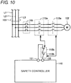
- FIG. 10 is a view to concretely explain a configuration for monitoring contactors.
- the power-supply line 103 includes lines L1, L2 and L3 corresponding to respective phases of the three-phase ACs.
- the motor 102 is connected to the power-supply line 103 through an a-contact 112a of the contactor 112, an a-contact 113a of the contactor 113, and a circuit breaker 105.
- the safety controller 110 is provided with a FB output terminal 121 and a FB input terminal 122.
- FB represents feedback.
- a b-contact 112b of the contactor 112 and a b-contact 113b of the contactor 113 are connected in series to each other between the FB output terminal 121 and the FB input terminal 122.
- the emergency stop switch 111 is omitted in FIG. 10 , in order to concentrate on describing the configuration of the contactors 112 and 113.
- a-contact refers to a contact that is opened when no current flows through the exciting coil, but is closed when a current flows therethrough.
- b-contact refers to a contact that is closed when no current flows through the exciting coil, but is opened when a current flows therethrough.
- a-contacts 112a and 113a of the contactors 112 and 113 directly operate distribution of a current to a hazard source (corresponding to, for example, the motor 102 of FIG. 11 ).
- a FB input represents a signal to be inputted to the safety controller 110.
- This FB input is inputted to the safety controller 110, so that the safety controller 110 can confirm that the a-contacts 112a and 113a of the contactors 112 and 113, respectively, are normally operating without welding failure. If the a-contact of any of the contactors 112 and 113 is welded, the safety controller 110 cannot cut off a current to the motor 102. Accordingly, it is necessary to detect the failure, such as the welding, of the a-contacts 112a and 113a of the contactors 112 and 113, respectively.
- contactors having a mechanical restriction in which the a-contact and the b-contact operate in relation to each other is used for each of the contactors 112 and 113.
- the b-contact is opened whenever the a-contact is closed, whereas the b-contact is closed whenever the a-contact is opened.
- the b-contacts 112b and 113b of the contactors 112 and 113, respectively, are connected in series to the FB input terminal 122 of the safety controller 110.
- the safety controller 110 outputs a safety output, which is a signal for permitting the operation of the contactors 112 and 113.
- the a-contacts 112a and 113a of the contactors 112 and 113, respectively, are closed in response to this safety output.
- the safety controller 110 Before outputting a safety output to the contactors 112 and 113, the safety controller 110 confirms that a feedback loop created by the b-contacts 112b and 113b of the contactors 112 and 113, respectively, has been closed. This operation corresponds to a FB monitor performed by the safety controller 110. If it is confirmed that the feedback loop has not been closed, or has been opened, the safety controller 110 does not turn on the safety output.
- a b-contact in the contactor is forcibly opened. This causes the feedback loop to be opened, so that the user can be aware of the failure.
- the reason why two contactors are provided is, when the welding of an a-contact is detected in one contactor, to cause the a-contact in the other contactor to be opened. It is believed that the possibility is low, in which both a-contacts 112a and 113a of the contactors 112 and 113, respectively, are welded. Therefore, arranging two contactors makes it possible to cut off the current to the motor 102 more reliably.
- JP 09-212206 A discloses a control device for a control route.
- This control device controls, for example, a brushless motor or a DC motor.
- JP 2003-504863 W discloses a method and system for driving a solenoid. On the basis of the difference between a desired current flow in a solenoid and an actual current flow therein, the solenoid driver controls the actual current flow in the solenoid.
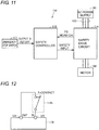
- FIG. 11 is a view illustrating another example of a configuration of a typical safety control system.
- a safety control system 152 includes a safety drive circuit 114, instead of the contactors 112 and 113.
- This safety drive circuit 114 may be, for example, a motor control apparatus, such as a servo driver, an inverter, or the like.
- a safety controller 110 monitors the FB of the safety drive circuit 114, similar to the safety control system 151 illustrated in FIG. 9 .
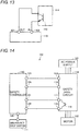
- FIG. 12 is a view to explain a feedback loop for controlling a contactor.
- FIG. 13 is a view to explain a feedback loop in a safety drive circuit.
- the b-contact of a contactor (which is exemplified by a b-contact 112b in FIG. 12 ) is connected between a FB output terminal (OUT) 121 and a FB input terminal (IN) 122 in the safety controller 110.
- the output signal from a semiconductor element 116 is used as a feedback monitor outputted from the safety drive circuit 114. The reason why a semiconductor element is used is to prolong the lifetime of the part that is responsible for a signal output function.
- the FB output terminal 121 of the safety controller 110 outputs a constant voltage (for example, DC 24 V).
- a voltage is inputted through the b-contact of the contactor or the semiconductor element. If the input voltage is at a high level, the safety controller 110 determines that the feedback loop has been closed. Otherwise, if the input voltage is at a low level, it determines that the feedback loop has been opened.
- FIG. 14 is a view to more concretely explain a connection between the safety controller and the safety drive circuit illustrated in FIG. 13 .
- the safety controller 110 includes the FB output terminal 121, the FB input terminal 122, a safety output (1) terminal 123, a safety output (2) terminal 124, and a safety input terminal 126.
- Each of the safety output (1) terminal 123 and the safety output (2) terminal 124 is a terminal that outputs a signal for permitting the operation of the safety drive circuit 114 (referred to as a "safety output").
- the safety drive circuit 114 includes a semiconductor element 116, a voltage input terminal 131, a FB monitor output terminal 132, a safety input (1) terminal 133, and a safety input (2) terminal 134.
- the semiconductor element 116 is provided between the voltage input terminal 131 and the FB monitor output terminal 132.
- Each of the safety input (1) terminal 133 and the safety input (2) terminal 134 is a terminal that inputs a safety output to the safety drive circuit 114 from the safety controller 110.
- a signal to be inputted to either of the safety input (1) terminal 133 and the safety input (2) terminal 134 is referred to as a "safety input".
- the safety output (1) terminal 123 of the safety controller 110 is connected directly to the safety input (1) terminal 133 of the safety drive circuit 114.
- the safety output (2) terminal 124 of the safety controller 110 is connected directly to the safety input (2) terminal 134 of the safety drive circuit 114.
- the FB output terminal 121 of the safety controller 110 is connected directly to the voltage input terminal 131 of the safety drive circuit 114.
- the FB input terminal 122 of the safety controller 110 is connected directly to the FB monitor output terminal 132 of the safety drive circuit 114.
- the FB output terminal 121 of the safety controller 110 outputs a signal of a high level.
- the safety controller 110 detects that a signal having been inputted to the FB input terminal 122 of the safety controller 110 is a signal of a high level.
- the safety output (1) terminal 123 and the safety output (2) terminal 124 of the safety controller 110 output respective signals of a high level.
- the reason why both of the safety output (1) terminal 123 and the safety output (2) terminal 124 in the safety controller 110 output signals of a high level is to increase the reliability of the safety output.
- both safe inputs 1 and 2 having been inputted to the safety drive circuit 114 are at a high level, the safety drive circuit 114 turns off the FB monitor output. Otherwise, if either of the safety inputs 1 and 2 is not at a high level, namely, at least one of them is at a low level, the FB monitor output is turned on.
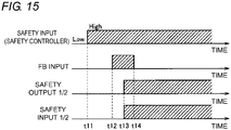
- FIG. 15 is a timing chart to explain the operation of the safety control system illustrated in FIG. 14 .
- both of the safety outputs 1 and 2 in the safety controller 110 (which will be described collectively as a "safety output 1/2" in FIG. 15 ) are at a low level.
- the safety output 1/2 is at the low level, the FB monitor output is in an "ON" state.
- the FB monitor output terminal 132 of the safety drive circuit 114 outputs a voltage.
- the input signal (safety input) that is inputted to the safety input terminal 126 of the safety controller 110 becomes a high level.
- the safety input also becomes a high level.
- the safety controller 110 detects that a signal inputted to the FB input terminal 122 has been a signal of a high level. With this, at a time t13, the safety output 1/2 of the safety controller 110 becomes a high level. Accordingly, the safety input 1/2 of the safety drive circuit 114 also becomes a high level. Once the safety input 1/2 becomes the high level, the safety drive circuit 114 turns off the semiconductor element 116. As a result, at a time t14, the FB monitor output is turned off.
- the semiconductor element 116 causes a voltage drop in the feedback loop of the safety drive circuit.
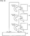
- individual semiconductor elements 116 of the safety drive circuits 114 are directly connected in series to the feedback input terminal of the safety controller 110, as illustrated in FIG. 16 .
- This configuration causes the remarkable voltage drop in the feedback loop of the safety controller 110, so that an input voltage at the FB input terminal 122 is greatly reduced.
- the safety controller 110 may determine that the feedback loop has been opened. In this case, the safety controller 110 does not turn on the safety output. As a result, it may be impossible for the safety controller 110 to permit the operations of the safety drive circuits 114 even when the safety drive circuits 114 can normally operate. In order to prevent such a great voltage drop from arising in the feedback loop, a configuration has been employed so far, in which only a limited number of safety drive circuits 114 are connected to a safety controller 110.
- JP 09-212206 A mentions a voltage drop in a servo driver (see the paragraph "0043" in the specification of JP 09-212206 A ), but lacks the description about the above disadvantage.
- JP 2003-504863 W does not describe this disadvantage.
- US 2008/0278875 A1 discloses a safety switching apparatus for failsafe disconnection of an electrical load that has a first and a second connecting terminal for connecting a first signaling switch and a third and a fourth connecting terminal for connecting a second signaling switch. It also has a first and a second output switching element, which are designed to produce a redundant output switching signal.
- the first connecting terminal is connected to a first potential and the third connecting terminal is connected to a second potential. The potentials differ from one another.
- the second connecting terminal is coupled to the first switching element in such a way that the first switching element receives the first potential via the first signaling switch.
- the fourth connecting terminal is coupled to the second switching element in such a way that the second switching element receives the second potential via the second signaling switch.
- a circuit arrangement may be provided for determining at least one further potential at the second and/or fourth connecting terminal, and said circuit arrangement may be designed to control the redundant output switching signal as a function of the further potential.
- US 7,116,069 B1 discloses that a rapid connection of multiple motor drive modules for safety operation may be made using screw terminals for initial connections to a safety controller and pre-wired cables for daisy chaining subsequent motor drives responsive to the same safety signals.
- Adaptor modules may be used to provide for a variety of different connector configurations depending on the location of the motor drive within the signal chain.
- An object of the present invention is to provide a safety control system that is capable of monitoring many more drive circuits by using a single controller without modifying the configurations of the controller and the drive circuits.
- a safety control system comprising a controller and at least one drive circuit according to claim 1.
- the controller further includes an auxiliary output terminal through which the controller outputs an auxiliary output signal that is synchronized with the output signal. After confirming that the feedback loop has been closed, the controller outputs the output signal and the auxiliary output signal through the signal output terminal and the auxiliary output terminal, respectively.
- the safety control system further includes a second relay.
- the second relay includes: a second coil; and a third contact which is opened when a current flows through the second coil but is closed when no current flows through the second coil.
- the first coil of the first relay and the third contact of the second relay are electrically connected in series to one another between the monitor output terminal of the drive circuit and the ground.
- the second coil of the second relay is electrically connected to the auxiliary output terminal of the controller and the ground.
- the at least one drive circuit includes a plurality of drive circuits.
- the at least one first relay includes a plurality of first relays provided corresponding to the plurality of drive circuits.
- the respective first contacts of the plurality of the first relays are electrically connected in series to one another between the feedback output terminal and the feedback input terminal of the controller.
- Each of the second contacts of the plurality of the first relays is electrically connected to the signal output terminal of the controller and the signal input terminal of one of the plurality of drive circuits which corresponds to each first relay.
- the respective first coils of the plurality of the first relays are electrically connected to the monitor output terminals of the corresponding drive circuits, and are connected in parallel to the third contact of the second relay.
- each of the first coils of the first relays prefferably be electrically connected to the ground and the monitor output terminal of a corresponding one of the drive circuits.
- the at least one drive circuit includes a plurality of drive circuits.
- the at least one first relay includes a plurality of first relays provided corresponding to the plurality of drive circuits.
- the respective first contacts of the plurality of the first relays are electrically connected in series to one another between the feedback output terminal and the feedback input terminal of the controller.
- the second contacts of the plurality of the first relays are electrically connected in series to one another, and each second contact is electrically connected to the signal output terminal of the controller and the signal input terminal of one of the drive circuits which corresponds to each first relay.
- FIG. 1 is a view illustrating an example of a configuration of a safety control system according to a first embodiment of the present invention.
- a safety control system 51 includes a safety controller 10, an input apparatus 11, a safety drive circuit 14, and relays 17 and 18.
- the input apparatus 11 is, for example, an emergency stop switch, but instead, it may be any other device having a function of inputting a signal to the safety controller 10 in accordance with a user's operation. For example, a light curtain or a door switch may be applied to the input apparatus 11.
- the input apparatus 11 is not limited to a single unit, but may be implemented by a combination of multiple units.
- a motor 2 serves as a power source, and operates by being supplied with three-phase ACs from an AC power supply 1.
- the motor 2 is driven by the safety drive circuit 14.
- the safety drive circuit 14 supplies drive electricity to the motor 2 from the AC power supply 1, and cuts off the electricity thereto.
- the safety drive circuit 14 may be a motor control apparatus, such as a servo driver, an inverter, or the like.
- the safety controller 10 has a function of monitoring the safety drive circuit 14. Note that the AC power supply 1 may be replaced by a DC power supply.
- safety controller and "safety drive circuit” are used. However, note that any of the “safety controller” and “safety drive circuit” does not represent any special device.
- the present invention is applicable to any given control device (controller) and driving device (drive circuit or driver), as long as they conform to predetermined safety specifications.
- the safety controller 10 includes a FB (feedback) output terminal 21, a FB input terminal 22, a safety output (1) terminal 23, a safety output (2) terminal 24, an auxiliary output terminal 25, and a safety input terminal 26.
- the FB output terminal 21 and the FB input terminal 22 are terminals that create a feedback loop through which the safety controller 10 monitors the state of the safety drive circuit 14.
- the expression "the state of the safety drive circuit 14" refers to a state where the output is permitted or cut off (for example, see FIG. 2 ).
- Each of the safety output (1) terminal 23 and the safety output (2) terminal 24 is a terminal, through which the safety controller 10 outputs a signal (referred to as a "safety output”) for permitting an operation of the safety drive circuit 14.
- the auxiliary output terminal 25 is a terminal, through which the safety controller 10 outputs a signal (referred to as an "auxiliary output") that is synchronized with the safety output.
- the safety input terminal 26 is a terminal, through which a signal (referred to as a "safety input") from the input apparatus 11 is inputted to the safety controller 10.
- the input apparatus 11 is connected to the safety input terminal 26 of the safety controller 10.
- the safety drive circuit 14 includes a semiconductor element 16, a voltage input terminal 31, a FB monitor output terminal 32, a safety input (1) terminal 33, and a safety input (2) terminal 34.
- the safety input (1) terminal 33 and the safety input (2) terminal 34 are terminals, through which safety outputs that have been outputted from the safety output (1) terminal 23 and the safety output (2) terminal 24, respectively, of the safety controller 10 are inputted to the safety drive circuit 14.
- a signal that is inputted to either of the safety input (1) terminal 33 and the safety input (2) terminal 34 is called a "safety input”.
- the present invention can be applied.
- the reliability of the safety control system can be further increased.
- the semiconductor element 16 is provided between the voltage input terminal 31 and the FB monitor output terminal 32.
- the FB monitor output terminal 32 is a monitor output terminal, through which the safety drive circuit 14 outputs a monitor voltage (FB monitor) indicating the state of the safety drive circuit 14 to the safety controller 10.
- the semiconductor element 16 generates a monitor voltage to be outputted from the FB monitor output terminal 32.
- the voltage input terminal 31 is a voltage input terminal, through which a voltage for causing the semiconductor element 16 to generate a monitor voltage is inputted to the semiconductor element 16. In this embodiment, the voltage input terminal 31 is connected to a constant voltage source.
- the safety drive circuit 14 outputs a FB monitor from the FB monitor output terminal 32, before respective output signals (safety outputs) from the safety controller 10 are inputted to the safety input (1) terminal and the safety input (2) terminal of the safety drive circuit 14, as will be described in detail.
- the relay 17 includes an a-contact 17a, a b-contact 17b, and a coil 17c.
- the a-contact 17a and the b-contact 17b are mechanically restricted, such that they operate in relation to each other in a complementary manner.
- the expression "complementary manner" indicates a state where one of the a-contact 17a and the b-contact 17b is "opened” when the other is "closed". Specifically, when the a-contact 17a is closed, the b-contact 17b is opened. Meanwhile, when the a-contact 17a is opened, the b-contact 17b is closed. Accordingly, both of the a-contact 17a and the b-contact 17b are not closed at the same time. In general, such a structure is also called a "force guided contact structure". Thus, any given relay is applicable to the relay 17, as long as being equipped with the force guided contact structure.
- the a-contact 17a corresponds to a "first contact of a first relay" according to the present invention.
- the b-contact 17b corresponds to a "second contact of the first relay” according to the present invention.
- the coil 17c corresponds to a "first coil of the first relay” according to the present invention.
- the a-contact 17a is electrically connected to the FB output terminal 21 and the FB input terminal 22 of the safety controller 10.
- the b-contact 17b is electrically connected to the safety output (1) terminal 23 of the safety controller 10 and the safety input (1) terminal 33 of the safety drive circuit 14.
- An end of the coil 17c is electrically connected to the FB monitor output terminal 32 of the safety drive circuit 14.
- the expression "electrical connection” includes not only a direct connection but also a connection through, for example, a wire.
- the relay 18 includes a b-contact 18b and a coil 18c.
- One end of the b-contact 18b is connected to the other end of the coil 17c of the relay 17, whereas the other end of the b-contact 18b is grounded.
- the coil 17c of the relay 17 and the b-contact 18b of the relay 18 are connected in series to one another between the FB monitor output terminal 32 of the safety drive circuit 14 and the ground.
- One end of the coil 18c is connected to the auxiliary output terminal 25 of the safety controller 10, whereas the other end of the coil 18c is connected to the ground.
- the coil 18c is electrically connected between the auxiliary output terminal 25 of the safety controller 10 and the ground.
- the force guided contact structure is not essential, and any general-purpose relay can be given as an example thereof.
- the b-contact 18b corresponds to a "third contact of a second relay" according to the present invention
- the coil 18c corresponds to a "second coil of the second relay” according to the present invention.
- a-contact 17a of the relay 17 is provided in the feedback loop of the safety controller 10, namely, on a route between the FB output terminal 21 and the FB input terminal 22 of the safety controller 10.
- the resistance of the a-contact 17a is much smaller than the ON-resistance of the semiconductor element 16. Accordingly, there is no substantial factor in a voltage drop across the above feedback loop.
- the relay 18 is driven by the auxiliary output that is synchronized with the safety output of the safety controller 10.
- the relay 17 is driven by the b-contact 18b of the relay 18 and the semiconductor element 16 of the safety drive circuit 14 (namely, the FB monitor output of the safety drive circuit 14).
- the b-contact 17b of the relay 17 may be provided between the safety output (2) terminal 24 of the safety controller 10 and the safety input (2) terminal 34 of the safety drive circuit 14.
- a b-contact of another relay equipped with the force guided contact structure may be provided between the safety output (2) terminal 24 of the safety controller 10 and the safety input (2) terminal 34 of the safety drive circuit 14.
- FIG. 2 is a view to explain an operation of the safety drive circuit illustrated in FIG. 1 .
- a "safety input 1" and a “safety input 2" represent signals to be inputted to the safety input (1) terminal 33 and the safety input (2) terminal 34, respectively, of the safety drive circuit 14. If both safety inputs 1 and 2 for the safety drive circuit 14 are at a high level, the output of the safety drive circuit 14 is permitted. In this case, the FB monitor output is turned off. Otherwise, if either of the safety inputs 1 and 2 for the safety drive circuit 14 is not at a high level, namely, if at least one of them is at a low level, the output of the safety drive circuit 14 is cut off. In this case, the FB monitor output is turned on.
- the output of the safety drive circuit 14 may be, for example, electricity supplied to the motor 2 from the safety drive circuit 14.
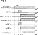
- FIG. 3 is a timing chart to explain an operation of the safety control system illustrated in FIG. 1 .
- the safety output 1 and the safety output 2 of the safety controller 10 (which are described collectively as a "safety output 1/2" in FIG. 3 ) are both at a low level.
- the safety output 1/2 is at the low level, the FB monitor output is in an ON state.
- the semiconductor element 16 is in an ON state, and the FB monitor output terminal 32 outputs a monitor voltage.
- a signal which is inputted to the safety input terminal 26 of the safety controller 10 from the input apparatus 11 becomes a high level.
- the safety input in response to a user's operation with the input apparatus, the safety input becomes a high level.
- the expression "a signal becomes a high level” means that a signal is being output. This will apply to the following description.
- a-contact 17a of the relay 17 is closed.
- the feedback loop is closed.
- a signal (FB input) that is inputted to the FB input terminal 22 of the safety controller 10 becomes a high level.
- This FB input of the high level causes the safety output 1/2 of the safety controller 10 to become a high level at a time t3.
- the auxiliary output becomes a high level in synchronization with the safety output 1/2.
- This auxiliary output becoming the high level causes a current to flow through the coil 18c of the relay 18. Following this, the relay 18 is turned on.
- the turn-on of the relay 18 causes the b-contact 18b to be opened.
- the turn-off of the relay 17 causes the a-contact 17a and the b-contact 17b to be opened and closed, respectively. Therefore, the safety input 1/2 that is inputted to the safety drive circuit 14 becomes a high level.
- This safety input 1/2 of the high level causes the semiconductor element 16 of the safety drive circuit 14 to be turned off. As a result, the FB monitor output is turned off.
- the operation of the safety control system according to this embodiment is basically the same as that of a typical safety control system. Specifically, after the FB input becomes a high level, the safety output 1/2 becomes a high level. The safety output 1/2 of the high level causes the safety input 1/2 to become a high level. Therefore, it is possible to apply an existing safety controller and safety drive circuit to the safety control system according to this embodiment.
- the safety controller 10 there is no factor in a voltage drop across the FB loop created by the safety controller 10. Accordingly, in the case where a plurality of safety drive circuits are connected to a single safety controller, the amount of the voltage drop arising in the FB loop is smaller than that in a typical configuration (see FIG. 16 ). This enables many more safety drive circuits to be connected to a single safety controller, in comparison with a typical configuration. Consequently, it is possible to increase the number of safety drive circuits which a single safety controller can monitor.
- FIG. 4 is a view illustrating a configuration of a safety control system according to the first embodiment, in which a plurality of safety drive circuits are connected to a single safety controller.
- the safety control system 52 differs from the safety control system 51 in further including a safety drive circuit 14A and a relay 19.
- the safety drive circuit 14A is configured to supply AC electricity to a motor 2A from an AC power supply 1A, or to cut off the AC electricity thereto. Note that in FIG. 4 , the AC power supplies 1 and 1A are illustrated, but instead, a single AC power supply may supply AC electricity to the motors 2 and 2A.
- the relay 19 includes an a-contact 19a, a b-contact 19b, and a coil 19c. Similar to the relay 17, the a-contact 19a and the b-contact 19b are mechanically restricted, such that they operate in relation to each other.
- the safety drive circuit 14A has a configuration that is the same as that of the safety drive circuit 14.
- the safety drive circuit 14A includes a semiconductor element 16A, a voltage input terminal 31A, a FB monitor output terminal 32A, a safety input (1) terminal 33A, and a safety input (2) terminal 34A.
- the a-contact 17a of the relay 17 and the a-contact 19a of the relay 19 are electrically connected in series to one another between the FB output terminal 21 and the FB input terminal 22 of the safety controller 10.
- the safety input (1) terminal 33A is connected to the b-contact 17b of the relay 17, together with the safety input (1) terminal 33 of the safety drive circuit 14.
- the safety input (2) terminal 34A is connected to the b-contact 19b of the relay 19, together with the safety input (2) terminal 34 of the safety drive circuit 14.
- the b-contact 17b of the relay 17 is electrically connected between a signal output terminal (or the safety output (1) terminal 23) of the safety controller 10 and a signal input terminal (or the safety input (1) terminal 33) of the safety drive circuit 14 which corresponds to the relay 17.
- the b-contact 19b of the relay 19 is electrically connected between a signal output terminal (or the safety output (2) terminal 24) of the safety controller 10 and a signal input terminal (or the safety input (2) terminal 34A) of the safety drive circuit 14A which corresponds to the relay 19.
- the b-contact 19b of the relay 19 may be inserted into a route that electrically connects the safety input (1) terminal 33 to the safety input (1) terminal 33A.
- One end of the coil 19c is connected to the FB monitor output terminal 32A of the safety drive circuit 14A, whereas the other end of the coil 19c is connected to the b-contact 18b of the relay 18. Accordingly, the coils 17c and 19c are connected in parallel to the b-contact 18b of the relay 18.
- the operation of the safety control system 52 illustrated in FIG. 4 is basically the same as that illustrated in FIG. 3 .
- the single safety controller 10 can also monitor three or more safety drive circuits in this embodiment. Relays (in which each pair of the a-contacts and the b-contacts are configured to operate in relation to each other in a mechanical manner), the number of which is the same as the number of the safety drive circuits, are provided, and the a-contacts of these relays are electrically connected in series between the FB output terminal 21 and the FB input terminal 22 of the safety controller 10.
- the b-contacts of the relays are electrically connected between a signal input terminal (or one of a safety input (1) terminal and a safety input (2) terminal) of a corresponding safety drive circuit and a signal output terminal (or a corresponding one of the safety output (1) terminal 23 and safety input (2) terminal 24) of the safety controller 10.
- the coils of the above relays are connected in parallel to the b-contact 18b of the relay 18.
- a single safety controller can monitor and control much more safety drive circuits than those in a typical configuration.
- a configuration in which a single safety controller monitors many more safety drive circuits can be simply constructed at a low cost.
- the relays 17 and 19 are used, each of which is mechanically restricted such that the a-contact and the b-contact operate in relation to each other.
- the a-contact of each relay is provided between the FB output terminal 21 and the FB input terminal 22 of the safety controller 10.
- the b-contact of each relay is provided between a safety output terminal of the safety controller 10 and a safety input terminal of a corresponding safety drive circuit.
- the FB monitor is basically used to find out the welding of the a-contacts 112a and 113a in the contactors 112 and 113, respectively. Moreover, when the drive output of the safety drive circuit 114 fails, the FB monitor output is maintained in an OFF state, thus preventing the safety output of the safety controller 110 from being maintained in an ON state and avoiding the dangerous condition. If the failure, such as the welding, of the a-contacts 112a and 113a cannot be detected, the safety output of the safety controller 110 may be turned on even when the FB monitor output is maintained in an OFF state.
- the b-contact 17b of the relay 17 (or the b-contact 19b of the relay 19) is forcibly opened when the a-contact 17a of the relay 17 (or the a-contact 19a of the relay 19) is welded.
- at least one of the safety inputs in the safety drive circuit (14 or 14A) is turned off.
- the safety drive circuit (14 or 14A) does not operate, so that the power source (or the motor 2) does not operate, either.
- the relay 18 may be a general-purpose relay.
- the possible failure of the relay 18 can be an ON or OFF failure.
- the output of the safety drive circuit 14 (or 14A) is cut off, even when any of an ON and OFF failures occurs.
- the relay 18 is kept OFF.
- the relay 17 (or 19) is maintained in an OFF state, whereas the a-contact (17a or 19a) of the relay 17 (or 19) is maintained being opened.
- the FB loop created by the safety controller 10 is opened.
- the safety outputs 1 and 2 of the safety controller 10 become a low level. Consequently, the outputs of the safety drive circuits (14 and 14A) are cut off.
- FIG. 5 is a view illustrating an example of a configuration of a safety control system according to a second embodiment of the present invention.
- a safety control system 53 according to the second embodiment is different from the safety control system 51 according to the first embodiment, in that the relay 18 is omitted.
- the safety controller 10 may be provided with the auxiliary output terminal 25, similar to the first embodiment, but this auxiliary output terminal 25 may be an option in the second embodiment. Therefore, the auxiliary output terminal 25 is not illustrated in FIG. 5 .
- One end of the coil 17c in the relay 17 is connected to the FB monitor output terminal 32 of the safety drive circuit 14. The other end of the coil 17c is grounded. Thus, in this embodiment, the coil 17c is electrically connected between the FB monitor output terminal 32 of the safety drive circuit 14 and the ground.
- the other part of the configuration which the safety control system 53 according to the second embodiment has is the same as corresponding part of the configuration which the safety control system 51 according to first embodiment has. Accordingly, the subsequent explanation will be skipped.
- FIG. 6 is a view to explain an operation of the safety drive circuit illustrated in FIG. 5 .
- the FB monitor output is turned off.
- the second embodiment differs from the first embodiment.
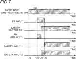
- FIG. 7 is a timing chart to explain an operation of the safety control system illustrated in FIG. 5 .
- the safety output 1 and the safety output 2 of the safety controller 10 (which are described collectively as a "safety output 1/2" in FIG. 7 ) are both at a low level.
- the safety output 1/2 is at the low level, the FB monitor output is in an ON state.
- a safety input which is inputted to the safety input terminal 26 of the safety controller 10 becomes a high level.
- the a-contact 17a of the relay 17 is closed. Accordingly, a signal (FB input) that is inputted to the FB input terminal 22 of the safety controller 10 becomes a high level.
- This FB input becoming the high level causes the safety output 1/2 of the safety controller 10 to become a high level at a time t3a.
- the b-contact 17b of the relay 17 is opened. Accordingly, the safety input 1 of the safety drive circuit 14 is at a low level at the time t3a. Meanwhile, the safety input 2 of the safety drive circuit 14 is at a high level.
- the safety inputs 1 and 2 becoming the low and high levels, respectively, in the safety drive circuit 14 cause the FB monitor output of the safety drive circuit 14 to be turned off. As a result, no current flows through the coil 17c of the relay 17, so that the relay 17 is turned off.
- the a-contact 17a of the relay 17 is opened but the b-contact 17b thereof is closed.
- the safety input 1 which is inputted to the safety drive circuit 14 becomes a high level.
- the safety inputs 1 and 2 are kept at the high level.
- the FB monitor output is at a low level.
- the FB monitor output is kept at the low level even after the time t4a.
- FIG. 8 is a view illustrating a configuration of a safety control system according to the second embodiment, in which a plurality of safety drive circuits are connected to a single safety controller.
- a safety control system 54 differs from the safety control system 53 in further including the safety drive circuit 14A and the relay 19. Note that because the configuration of the safety drive circuit 14A is the same as that illustrated in FIG. 4 , the subsequent description will be skipped. Likewise, because the configuration of the relay 19 is the same as that illustrated in FIG. 4 , the subsequent description will be skipped.
- the b-contact 17b of the relay 17 and the b-contact 19b of the relay 19 are connected in series to one another between the safety output (1) terminal 23 of the safety controller 10 and the safety input (1) terminal (33 or 33A) of the safety drive circuit (14 or 14A).
- the coil 19c of the relay 19 is electrically connected to the FB monitor output terminal 32A of the safety drive circuit 14A and the ground. Note that in the configuration illustrated in FIG. 8 , the coil 17c of the relay 17 and the coil 19c of the relay 19 are connected to the ground together, but may be connected to the ground separately.
- the configuration according to the second embodiment can make the relay 18 unnecessary, even when a plurality of safety drive circuits are connected to a single safety controller.
- the b-contact 17b of the relay 17 and the b-contact 19b of the relay 19 may be connected in series to one another between the safety output (2) terminal 24 of the safety controller 10 and the safety input (2) terminal (34 or 34A) of the safety drive circuit (14 or 14A).
- the safety drive circuits (14 and 14A) operate in accordance with the relationship illustrated in FIG. 7 . Accordingly, it is necessary to connect one of the two safety input terminals in each of the safety drive circuits (14 and 14A) to a corresponding safety output terminal of the safety controller 10 without a b-contact therebetween, namely, directly.
- the second embodiment can produce the same effect as the first embodiment does.
- a configuration in which a single safety controller monitors many more safety drive circuits can be simply constructed at a low cost.
- the second embodiment can decrease the number of relays used therein, in comparison with the first embodiment.
Description
- The present invention relates to a safety control system, in particular, a configuration in which a single controller monitors a plurality of drive circuits.
- In order to establish work safety in production sites, safety control systems are constructed, in which electricity is supplied to a power source, such as a motor, for mechanical equipment in the state where safety is secured. Such a safety control system includes, for example, a relay unit and a controller.
-
FIG. 9 is a view illustrating an example of a configuration of a typical safety control system. Referring toFIG. 9 , amotor 102 serves as a power source and is operated by being supplied with three-phase ACs from anAC power supply 101. Thismotor 102 is used to, for example, drive various mechanical devices in a factory. Asafety control system 151 supplies drive electricity to themotor 102 from theAC power supply 101 or cuts off the drive electricity thereto. - The
safety control system 151 includes asafety controller 110, anemergency stop switch 111, andcontactors emergency stop switch 111 is illustrated inFIG. 9 as an example of an input apparatus connected to thesafety controller 110. The input apparatus may also be a light curtain or a door switch. Thecontactors supply line 103 between theAC power supply 101 and themotor 102. Thesafety controller 110 has a function of monitoring thecontactors -
FIG. 10 is a view to concretely explain a configuration for monitoring contactors. Referring toFIGS. 9 and10 , the power-supply line 103 includes lines L1, L2 and L3 corresponding to respective phases of the three-phase ACs. Themotor 102 is connected to the power-supply line 103 through an a-contact 112a of thecontactor 112, an a-contact 113a of thecontactor 113, and acircuit breaker 105. - The
safety controller 110 is provided with aFB output terminal 121 and aFB input terminal 122. Note that the term "FB" represents feedback. A b-contact 112b of thecontactor 112 and a b-contact 113b of thecontactor 113 are connected in series to each other between theFB output terminal 121 and theFB input terminal 122. Note that theemergency stop switch 111 is omitted inFIG. 10 , in order to concentrate on describing the configuration of thecontactors - In general, with regard to a switch, such as a relay or a contactor, which opens or closes the contact by feeding a current to the exciting coil, a term "a-contact" refers to a contact that is opened when no current flows through the exciting coil, but is closed when a current flows therethrough. Meanwhile, the term "b-contact" refers to a contact that is closed when no current flows through the exciting coil, but is opened when a current flows therethrough. The above definitions of the "a-contact" and "b-contact" also apply to the following description.
- In the configuration illustrated in
FIGS. 9 and10 , the a-contacts 112a and 113a of thecontactors motor 102 ofFIG. 11 ). InFIG. 9 , a FB input represents a signal to be inputted to thesafety controller 110. This FB input is inputted to thesafety controller 110, so that thesafety controller 110 can confirm that the a-contacts 112a and 113a of thecontactors contactors safety controller 110 cannot cut off a current to themotor 102. Accordingly, it is necessary to detect the failure, such as the welding, of the a-contacts 112a and 113a of thecontactors - When a safety control system, such as that illustrated in
FIGS. 9 and10 , is designed, contactors having a mechanical restriction in which the a-contact and the b-contact operate in relation to each other is used for each of thecontactors - As illustrated in
FIG. 10 , the b-contacts contactors FB input terminal 122 of thesafety controller 110. Thesafety controller 110 outputs a safety output, which is a signal for permitting the operation of thecontactors contactors - Before outputting a safety output to the
contactors safety controller 110 confirms that a feedback loop created by the b-contacts contactors safety controller 110. If it is confirmed that the feedback loop has not been closed, or has been opened, thesafety controller 110 does not turn on the safety output. - Assuming a case where an a-contactor in at least one of the
contactors contactors motor 102 more reliably. - To give an example,
JP 09-212206 A - To give another example,
JP 2003-504863 W -
FIG. 11 is a view illustrating another example of a configuration of a typical safety control system. Referring toFIGS. 9 and11 , asafety control system 152 includes asafety drive circuit 114, instead of thecontactors safety drive circuit 114 may be, for example, a motor control apparatus, such as a servo driver, an inverter, or the like. Asafety controller 110 monitors the FB of thesafety drive circuit 114, similar to thesafety control system 151 illustrated inFIG. 9 . -
FIG. 12 is a view to explain a feedback loop for controlling a contactor.FIG. 13 is a view to explain a feedback loop in a safety drive circuit. Referring toFIGS. 12 and13 , the b-contact of a contactor (which is exemplified by a b-contact 112b inFIG. 12 ) is connected between a FB output terminal (OUT) 121 and a FB input terminal (IN) 122 in thesafety controller 110. Meanwhile, in many similar cases, the output signal from asemiconductor element 116 is used as a feedback monitor outputted from thesafety drive circuit 114. The reason why a semiconductor element is used is to prolong the lifetime of the part that is responsible for a signal output function. - The
FB output terminal 121 of thesafety controller 110 outputs a constant voltage (for example, DC 24 V). To theFB input terminal 122 of thesafety controller 110, a voltage is inputted through the b-contact of the contactor or the semiconductor element. If the input voltage is at a high level, thesafety controller 110 determines that the feedback loop has been closed. Otherwise, if the input voltage is at a low level, it determines that the feedback loop has been opened. -
FIG. 14 is a view to more concretely explain a connection between the safety controller and the safety drive circuit illustrated inFIG. 13 . Referring toFIG. 14 , thesafety controller 110 includes theFB output terminal 121, theFB input terminal 122, a safety output (1)terminal 123, a safety output (2)terminal 124, and asafety input terminal 126. Each of the safety output (1)terminal 123 and the safety output (2)terminal 124 is a terminal that outputs a signal for permitting the operation of the safety drive circuit 114 (referred to as a "safety output"). - The
safety drive circuit 114 includes asemiconductor element 116, avoltage input terminal 131, a FBmonitor output terminal 132, a safety input (1)terminal 133, and a safety input (2)terminal 134. Thesemiconductor element 116 is provided between thevoltage input terminal 131 and the FBmonitor output terminal 132. Each of the safety input (1)terminal 133 and the safety input (2)terminal 134 is a terminal that inputs a safety output to thesafety drive circuit 114 from thesafety controller 110. A signal to be inputted to either of the safety input (1)terminal 133 and the safety input (2)terminal 134 is referred to as a "safety input". - The safety output (1)
terminal 123 of thesafety controller 110 is connected directly to the safety input (1)terminal 133 of thesafety drive circuit 114. The safety output (2)terminal 124 of thesafety controller 110 is connected directly to the safety input (2)terminal 134 of thesafety drive circuit 114. TheFB output terminal 121 of thesafety controller 110 is connected directly to thevoltage input terminal 131 of thesafety drive circuit 114. TheFB input terminal 122 of thesafety controller 110 is connected directly to the FBmonitor output terminal 132 of thesafety drive circuit 114. - The
FB output terminal 121 of thesafety controller 110 outputs a signal of a high level. Thesafety controller 110 detects that a signal having been inputted to theFB input terminal 122 of thesafety controller 110 is a signal of a high level. In this case, the safety output (1)terminal 123 and the safety output (2)terminal 124 of thesafety controller 110 output respective signals of a high level. The reason why both of the safety output (1)terminal 123 and the safety output (2) terminal 124 in thesafety controller 110 output signals of a high level is to increase the reliability of the safety output. - If both
safe inputs safety drive circuit 114 are at a high level, thesafety drive circuit 114 turns off the FB monitor output. Otherwise, if either of thesafety inputs -
FIG. 15 is a timing chart to explain the operation of the safety control system illustrated inFIG. 14 . Referring toFIGS. 14 and15 , first, in an initial state (a state prior to a time t11), both of thesafety outputs safety output 1/2" inFIG. 15 ) are at a low level. Although not illustrated in figures, because thesafety output 1/2 is at the low level, the FB monitor output is in an "ON" state. Thus, the FBmonitor output terminal 132 of thesafety drive circuit 114 outputs a voltage. - At a time t11, next, the input signal (safety input) that is inputted to the
safety input terminal 126 of thesafety controller 110 becomes a high level. In response to this, the safety input also becomes a high level. - At a time t12, subsequently, the
safety controller 110 detects that a signal inputted to theFB input terminal 122 has been a signal of a high level. With this, at a time t13, thesafety output 1/2 of thesafety controller 110 becomes a high level. Accordingly, thesafety input 1/2 of thesafety drive circuit 114 also becomes a high level. Once thesafety input 1/2 becomes the high level, thesafety drive circuit 114 turns off thesemiconductor element 116. As a result, at a time t14, the FB monitor output is turned off. - However, the
semiconductor element 116 causes a voltage drop in the feedback loop of the safety drive circuit. In the case where asingle safety controller 110 administrates a plurality ofsafety drive circuits 114,individual semiconductor elements 116 of thesafety drive circuits 114 are directly connected in series to the feedback input terminal of thesafety controller 110, as illustrated inFIG. 16 . This configuration causes the remarkable voltage drop in the feedback loop of thesafety controller 110, so that an input voltage at theFB input terminal 122 is greatly reduced. - When an input voltage at the
FB input terminal 122 is considerably low, thesafety controller 110 may determine that the feedback loop has been opened. In this case, thesafety controller 110 does not turn on the safety output. As a result, it may be impossible for thesafety controller 110 to permit the operations of thesafety drive circuits 114 even when thesafety drive circuits 114 can normally operate. In order to prevent such a great voltage drop from arising in the feedback loop, a configuration has been employed so far, in which only a limited number ofsafety drive circuits 114 are connected to asafety controller 110. - As a solution to the above disadvantage, it is contemplated that the configuration of a safety controller or a safety drive circuit needs to be modified. However, this solution may involve a risk of increasing the number of man-hours devoted to the development along with the design modification. As a result, this leads to an increase in the overall cost. Moreover, it is necessary to confirm and certify that the modified safety controller or safety drive circuit meets target safety specifications. In order to do so, additional cost and time may be required.
- As for the above-mentioned patent documents,
JP 09-212206 A JP 09-212206 A JP 2003-504863 W -
US 2008/0278875 A1 discloses a safety switching apparatus for failsafe disconnection of an electrical load that has a first and a second connecting terminal for connecting a first signaling switch and a third and a fourth connecting terminal for connecting a second signaling switch. It also has a first and a second output switching element, which are designed to produce a redundant output switching signal. The first connecting terminal is connected to a first potential and the third connecting terminal is connected to a second potential. The potentials differ from one another. In addition, the second connecting terminal is coupled to the first switching element in such a way that the first switching element receives the first potential via the first signaling switch.; Likewise, the fourth connecting terminal is coupled to the second switching element in such a way that the second switching element receives the second potential via the second signaling switch. A circuit arrangement may be provided for determining at least one further potential at the second and/or fourth connecting terminal, and said circuit arrangement may be designed to control the redundant output switching signal as a function of the further potential. -
US 7,116,069 B1 discloses that a rapid connection of multiple motor drive modules for safety operation may be made using screw terminals for initial connections to a safety controller and pre-wired cables for daisy chaining subsequent motor drives responsive to the same safety signals. Adaptor modules may be used to provide for a variety of different connector configurations depending on the location of the motor drive within the signal chain. - An object of the present invention is to provide a safety control system that is capable of monitoring many more drive circuits by using a single controller without modifying the configurations of the controller and the drive circuits.
- In accordance with one aspect of the present invention, the object is solved by a safety control system comprising a controller and at least one drive circuit according to
claim 1. - It is preferable for the controller to further include an auxiliary output terminal through which the controller outputs an auxiliary output signal that is synchronized with the output signal. After confirming that the feedback loop has been closed, the controller outputs the output signal and the auxiliary output signal through the signal output terminal and the auxiliary output terminal, respectively. The safety control system further includes a second relay. The second relay includes: a second coil; and a third contact which is opened when a current flows through the second coil but is closed when no current flows through the second coil. The first coil of the first relay and the third contact of the second relay are electrically connected in series to one another between the monitor output terminal of the drive circuit and the ground. The second coil of the second relay is electrically connected to the auxiliary output terminal of the controller and the ground.
- It is preferable for the at least one drive circuit to include a plurality of drive circuits. The at least one first relay includes a plurality of first relays provided corresponding to the plurality of drive circuits. The respective first contacts of the plurality of the first relays are electrically connected in series to one another between the feedback output terminal and the feedback input terminal of the controller. Each of the second contacts of the plurality of the first relays is electrically connected to the signal output terminal of the controller and the signal input terminal of one of the plurality of drive circuits which corresponds to each first relay. The respective first coils of the plurality of the first relays are electrically connected to the monitor output terminals of the corresponding drive circuits, and are connected in parallel to the third contact of the second relay.
- It is preferable for each of the first coils of the first relays to be electrically connected to the ground and the monitor output terminal of a corresponding one of the drive circuits.
- It is preferable for the at least one drive circuit to include a plurality of drive circuits. The at least one first relay includes a plurality of first relays provided corresponding to the plurality of drive circuits. The respective first contacts of the plurality of the first relays are electrically connected in series to one another between the feedback output terminal and the feedback input terminal of the controller. The second contacts of the plurality of the first relays are electrically connected in series to one another, and each second contact is electrically connected to the signal output terminal of the controller and the signal input terminal of one of the drive circuits which corresponds to each first relay.
- With the present invention, it is possible to provide a safety control system which is capable of monitoring many more drive circuits by using a single controller without modifying the configurations of the controller and the drive circuit.
-
-
FIG. 1 is a view illustrating an example of a configuration of a safety control system according to a first embodiment of the present invention; -
FIG. 2 is a view to explain an operation of a safety drive circuit illustrated inFIG. 1 ; -
FIG. 3 is a timing chart to explain an operation of the safety control system illustrated inFIG. 1 ; -
FIG. 4 is a view illustrating a configuration of a safety control system according to the first embodiment, in which a plurality of safety drive circuits are connected to a single safety controller; -
FIG. 5 is a view illustrating an example of a configuration of a safety control system according to a second embodiment of the present invention; -
FIG. 6 is a view to explain an operation of a safety drive circuit illustrated inFIG. 5 ; -
FIG. 7 is a timing chart to explain an operation of the safety control system illustrated inFIG. 5 ; -
FIG. 8 is a view illustrating a configuration of a safety control system according to the second embodiment, in which a plurality of safety drive circuits are connected to a single safety controller; -
FIG. 9 is a view illustrating an example of a configuration of a typical safety control system; -
FIG. 10 is a view to concretely explain a configuration for monitoring contactors; -
FIG. 11 is a view illustrating another example of a configuration of a typical safety control system; -
FIG. 12 is a view to explain a feedback loop for controlling a contactor; -
FIG. 13 is a view to explain a feedback loop in a safety drive circuit. -
FIG. 14 is a view to more concretely explain a connection between a safety controller and the safety drive circuit illustrated inFIG. 13 ; -
FIG. 15 is a timing chart to explain an operation of the safety control system illustrated inFIG. 14 ; and -
FIG. 16 is a view to explain a disadvantage arising when a feedback loop is created by the semiconductor elements of the safety drive circuits that are connected in series to one another. - Hereinafter, embodiments of the present invention will be described in detail, with reference to the accompanying drawings. Note that the same or equivalent components in the drawings will be given the same reference numbers, and no descriptions thereof will be repeated.
-
FIG. 1 is a view illustrating an example of a configuration of a safety control system according to a first embodiment of the present invention. - Referring to
FIG. 1 , asafety control system 51 according to the first embodiment includes asafety controller 10, aninput apparatus 11, asafety drive circuit 14, and relays 17 and 18. Theinput apparatus 11 is, for example, an emergency stop switch, but instead, it may be any other device having a function of inputting a signal to thesafety controller 10 in accordance with a user's operation. For example, a light curtain or a door switch may be applied to theinput apparatus 11. In addition, theinput apparatus 11 is not limited to a single unit, but may be implemented by a combination of multiple units. - A
motor 2 serves as a power source, and operates by being supplied with three-phase ACs from anAC power supply 1. Themotor 2 is driven by thesafety drive circuit 14. Thesafety drive circuit 14 supplies drive electricity to themotor 2 from theAC power supply 1, and cuts off the electricity thereto. Thesafety drive circuit 14 may be a motor control apparatus, such as a servo driver, an inverter, or the like. Thesafety controller 10 has a function of monitoring thesafety drive circuit 14. Note that theAC power supply 1 may be replaced by a DC power supply. - In the description herein, the terms "safety controller" and "safety drive circuit" are used. However, note that any of the "safety controller" and "safety drive circuit" does not represent any special device. The present invention is applicable to any given control device (controller) and driving device (drive circuit or driver), as long as they conform to predetermined safety specifications.
- The
safety controller 10 includes a FB (feedback)output terminal 21, aFB input terminal 22, a safety output (1)terminal 23, a safety output (2)terminal 24, anauxiliary output terminal 25, and asafety input terminal 26. TheFB output terminal 21 and theFB input terminal 22 are terminals that create a feedback loop through which thesafety controller 10 monitors the state of thesafety drive circuit 14. In this embodiment, the expression "the state of thesafety drive circuit 14" refers to a state where the output is permitted or cut off (for example, seeFIG. 2 ). Each of the safety output (1)terminal 23 and the safety output (2)terminal 24 is a terminal, through which thesafety controller 10 outputs a signal (referred to as a "safety output") for permitting an operation of thesafety drive circuit 14. Theauxiliary output terminal 25 is a terminal, through which thesafety controller 10 outputs a signal (referred to as an "auxiliary output") that is synchronized with the safety output. Thesafety input terminal 26 is a terminal, through which a signal (referred to as a "safety input") from theinput apparatus 11 is inputted to thesafety controller 10. Theinput apparatus 11 is connected to thesafety input terminal 26 of thesafety controller 10. - The
safety drive circuit 14 includes asemiconductor element 16, avoltage input terminal 31, a FBmonitor output terminal 32, a safety input (1)terminal 33, and a safety input (2)terminal 34. The safety input (1)terminal 33 and the safety input (2)terminal 34 are terminals, through which safety outputs that have been outputted from the safety output (1)terminal 23 and the safety output (2)terminal 24, respectively, of thesafety controller 10 are inputted to thesafety drive circuit 14. A signal that is inputted to either of the safety input (1)terminal 33 and the safety input (2)terminal 34 is called a "safety input". - As long as at least one set of a safety output terminal of the
safety controller 10 and a safety input terminal of thesafety drive circuit 14 are provided, the present invention can be applied. However, by providing two or more sets of a safety output terminal and a safety input terminal as in this embodiment, the reliability of the safety control system can be further increased. - The
semiconductor element 16 is provided between thevoltage input terminal 31 and the FBmonitor output terminal 32. The FB monitoroutput terminal 32 is a monitor output terminal, through which thesafety drive circuit 14 outputs a monitor voltage (FB monitor) indicating the state of thesafety drive circuit 14 to thesafety controller 10. Thesemiconductor element 16 generates a monitor voltage to be outputted from the FBmonitor output terminal 32. Thevoltage input terminal 31 is a voltage input terminal, through which a voltage for causing thesemiconductor element 16 to generate a monitor voltage is inputted to thesemiconductor element 16. In this embodiment, thevoltage input terminal 31 is connected to a constant voltage source. Note that thesafety drive circuit 14 outputs a FB monitor from the FBmonitor output terminal 32, before respective output signals (safety outputs) from thesafety controller 10 are inputted to the safety input (1) terminal and the safety input (2) terminal of thesafety drive circuit 14, as will be described in detail. - The
relay 17 includes an a-contact 17a, a b-contact 17b, and acoil 17c. The a-contact 17a and the b-contact 17b are mechanically restricted, such that they operate in relation to each other in a complementary manner. In this embodiment, the expression "complementary manner" indicates a state where one of the a-contact 17a and the b-contact 17b is "opened" when the other is "closed". Specifically, when the a-contact 17a is closed, the b-contact 17b is opened. Meanwhile, when the a-contact 17a is opened, the b-contact 17b is closed. Accordingly, both of the a-contact 17a and the b-contact 17b are not closed at the same time. In general, such a structure is also called a "force guided contact structure". Thus, any given relay is applicable to therelay 17, as long as being equipped with the force guided contact structure. - The a-contact 17a corresponds to a "first contact of a first relay" according to the present invention. The b-
contact 17b corresponds to a "second contact of the first relay" according to the present invention. Thecoil 17c corresponds to a "first coil of the first relay" according to the present invention. - The a-contact 17a is electrically connected to the
FB output terminal 21 and theFB input terminal 22 of thesafety controller 10. The b-contact 17b is electrically connected to the safety output (1)terminal 23 of thesafety controller 10 and the safety input (1)terminal 33 of thesafety drive circuit 14. An end of thecoil 17c is electrically connected to the FBmonitor output terminal 32 of thesafety drive circuit 14. Herein, the expression "electrical connection" includes not only a direct connection but also a connection through, for example, a wire. - The
relay 18 includes a b-contact 18b and acoil 18c. One end of the b-contact 18b is connected to the other end of thecoil 17c of therelay 17, whereas the other end of the b-contact 18b is grounded. In other words, thecoil 17c of therelay 17 and the b-contact 18b of therelay 18 are connected in series to one another between the FBmonitor output terminal 32 of thesafety drive circuit 14 and the ground. One end of thecoil 18c is connected to theauxiliary output terminal 25 of thesafety controller 10, whereas the other end of thecoil 18c is connected to the ground. In other words, thecoil 18c is electrically connected between theauxiliary output terminal 25 of thesafety controller 10 and the ground. - For the
relay 18, the force guided contact structure is not essential, and any general-purpose relay can be given as an example thereof. The b-contact 18b corresponds to a "third contact of a second relay" according to the present invention, and thecoil 18c corresponds to a "second coil of the second relay" according to the present invention. - According to the configuration illustrated in
FIG. 1 , only the a-contact 17a of therelay 17 is provided in the feedback loop of thesafety controller 10, namely, on a route between theFB output terminal 21 and theFB input terminal 22 of thesafety controller 10. The resistance of the a-contact 17a is much smaller than the ON-resistance of thesemiconductor element 16. Accordingly, there is no substantial factor in a voltage drop across the above feedback loop. - The
relay 18 is driven by the auxiliary output that is synchronized with the safety output of thesafety controller 10. Therelay 17 is driven by the b-contact 18b of therelay 18 and thesemiconductor element 16 of the safety drive circuit 14 (namely, the FB monitor output of the safety drive circuit 14). - In this embodiment, it is only necessary to provide a b-contact of a relay equipped with the force guided contact structure in a connection between at least one of two safety output terminals of the
safety controller 10 and a safety input terminal of thesafety drive circuit 14 which corresponds to the at least one safety output terminal. Accordingly, as opposed to the configuration illustrated inFIG. 1 , the b-contact 17b of therelay 17 may be provided between the safety output (2)terminal 24 of thesafety controller 10 and the safety input (2)terminal 34 of thesafety drive circuit 14. Alternatively, in the configuration illustrated inFIG. 1 , a b-contact of another relay equipped with the force guided contact structure may be provided between the safety output (2)terminal 24 of thesafety controller 10 and the safety input (2)terminal 34 of thesafety drive circuit 14. -
FIG. 2 is a view to explain an operation of the safety drive circuit illustrated inFIG. 1 . InFIG. 2 , a "safety input 1" and a "safety input 2" represent signals to be inputted to the safety input (1)terminal 33 and the safety input (2)terminal 34, respectively, of thesafety drive circuit 14. If bothsafety inputs safety drive circuit 14 are at a high level, the output of thesafety drive circuit 14 is permitted. In this case, the FB monitor output is turned off. Otherwise, if either of thesafety inputs safety drive circuit 14 is not at a high level, namely, if at least one of them is at a low level, the output of thesafety drive circuit 14 is cut off. In this case, the FB monitor output is turned on. The output of thesafety drive circuit 14 may be, for example, electricity supplied to themotor 2 from thesafety drive circuit 14. -
FIG. 3 is a timing chart to explain an operation of the safety control system illustrated inFIG. 1 . Referring toFIGS. 1 and3 , first, in an initial state (or a state prior to a time t1), thesafety output 1 and thesafety output 2 of the safety controller 10 (which are described collectively as a "safety output 1/2" inFIG. 3 ) are both at a low level. Although not illustrated inFIG. 3 , because thesafety output 1/2 is at the low level, the FB monitor output is in an ON state. Thus, in thesafety drive circuit 14, thesemiconductor element 16 is in an ON state, and the FBmonitor output terminal 32 outputs a monitor voltage. - Because the auxiliary output of the
safety controller 10 is at a low level, no current flows through thecoil 18c. As a result, the b-contact 18b of the relay 18 (RY2) is closed. This causes a current to flow from the FBmonitor output terminal 32 of thesafety drive circuit 14 to thecoil 17c of the relay 17 (RY1) and the b-contact 18b of therelay 18. Due to the current flowing through thecoil 17c, therelay 17 is turned on. - At a time t1, next, a signal (safe input) which is inputted to the
safety input terminal 26 of thesafety controller 10 from theinput apparatus 11 becomes a high level. Concretely, in response to a user's operation with the input apparatus, the safety input becomes a high level. Note that in this embodiment, the expression "a signal becomes a high level" means that a signal is being output. This will apply to the following description. - At a time t2, subsequently, the a-contact 17a of the
relay 17 is closed. As a result, the feedback loop is closed. Accordingly, a signal (FB input) that is inputted to theFB input terminal 22 of thesafety controller 10 becomes a high level. This FB input of the high level causes thesafety output 1/2 of thesafety controller 10 to become a high level at a time t3. The auxiliary output becomes a high level in synchronization with thesafety output 1/2. This auxiliary output becoming the high level causes a current to flow through thecoil 18c of therelay 18. Following this, therelay 18 is turned on. - The turn-on of the
relay 18 causes the b-contact 18b to be opened. As a result, no current flows through thecoil 17c of therelay 17, which causes therelay 17 to be turned off at a time t4. The turn-off of therelay 17 causes the a-contact 17a and the b-contact 17b to be opened and closed, respectively. Therefore, thesafety input 1/2 that is inputted to thesafety drive circuit 14 becomes a high level. Thissafety input 1/2 of the high level causes thesemiconductor element 16 of thesafety drive circuit 14 to be turned off. As a result, the FB monitor output is turned off. - Note that in
FIG. 3 , the marks of times t1, t2, t3 and t4 are away from one another, for better understanding of the sequence of the operations. However, these operations are performed at substantially the same timing. - As can be understood from the comparison between the timing charts of
FIGS. 3 and15 , the operation of the safety control system according to this embodiment is basically the same as that of a typical safety control system. Specifically, after the FB input becomes a high level, thesafety output 1/2 becomes a high level. Thesafety output 1/2 of the high level causes thesafety input 1/2 to become a high level. Therefore, it is possible to apply an existing safety controller and safety drive circuit to the safety control system according to this embodiment. - According to this embodiment, there is no factor in a voltage drop across the FB loop created by the
safety controller 10. Accordingly, in the case where a plurality of safety drive circuits are connected to a single safety controller, the amount of the voltage drop arising in the FB loop is smaller than that in a typical configuration (seeFIG. 16 ). This enables many more safety drive circuits to be connected to a single safety controller, in comparison with a typical configuration. Consequently, it is possible to increase the number of safety drive circuits which a single safety controller can monitor. -
FIG. 4 is a view illustrating a configuration of a safety control system according to the first embodiment, in which a plurality of safety drive circuits are connected to a single safety controller. Referring toFIGS. 1 and4 , thesafety control system 52 differs from thesafety control system 51 in further including asafety drive circuit 14A and arelay 19. Thesafety drive circuit 14A is configured to supply AC electricity to amotor 2A from anAC power supply 1A, or to cut off the AC electricity thereto. Note that inFIG. 4 , theAC power supplies motors - The
relay 19 includes an a-contact 19a, a b-contact 19b, and acoil 19c. Similar to therelay 17, the a-contact 19a and the b-contact 19b are mechanically restricted, such that they operate in relation to each other. - The
safety drive circuit 14A has a configuration that is the same as that of thesafety drive circuit 14. In more detail, thesafety drive circuit 14A includes asemiconductor element 16A, avoltage input terminal 31A, a FBmonitor output terminal 32A, a safety input (1) terminal 33A, and a safety input (2) terminal 34A. - The a-contact 17a of the
relay 17 and the a-contact 19a of therelay 19 are electrically connected in series to one another between theFB output terminal 21 and theFB input terminal 22 of thesafety controller 10. The safety input (1) terminal 33A is connected to the b-contact 17b of therelay 17, together with the safety input (1)terminal 33 of thesafety drive circuit 14. The safety input (2) terminal 34A is connected to the b-contact 19b of therelay 19, together with the safety input (2)terminal 34 of thesafety drive circuit 14. - Specifically, the b-
contact 17b of therelay 17 is electrically connected between a signal output terminal (or the safety output (1) terminal 23) of thesafety controller 10 and a signal input terminal (or the safety input (1) terminal 33) of thesafety drive circuit 14 which corresponds to therelay 17. Meanwhile, the b-contact 19b of therelay 19 is electrically connected between a signal output terminal (or the safety output (2) terminal 24) of thesafety controller 10 and a signal input terminal (or the safety input (2) terminal 34A) of thesafety drive circuit 14A which corresponds to therelay 19. Note that the b-contact 19b of therelay 19 may be inserted into a route that electrically connects the safety input (1) terminal 33 to the safety input (1) terminal 33A. - One end of the
coil 19c is connected to the FBmonitor output terminal 32A of thesafety drive circuit 14A, whereas the other end of thecoil 19c is connected to the b-contact 18b of therelay 18. Accordingly, thecoils contact 18b of therelay 18. - The operation of the
safety control system 52 illustrated inFIG. 4 is basically the same as that illustrated inFIG. 3 . InFIG. 3 , it is only necessary to substitute therelays safety inputs 1/2 of thesafety drive circuits safety input 1/2. - Although two safety drive circuits are illustrated in
FIG. 4 , thesingle safety controller 10 can also monitor three or more safety drive circuits in this embodiment. Relays (in which each pair of the a-contacts and the b-contacts are configured to operate in relation to each other in a mechanical manner), the number of which is the same as the number of the safety drive circuits, are provided, and the a-contacts of these relays are electrically connected in series between theFB output terminal 21 and theFB input terminal 22 of thesafety controller 10. Furthermore, the b-contacts of the relays are electrically connected between a signal input terminal (or one of a safety input (1) terminal and a safety input (2) terminal) of a corresponding safety drive circuit and a signal output terminal (or a corresponding one of the safety output (1)terminal 23 and safety input (2) terminal 24) of thesafety controller 10. The coils of the above relays are connected in parallel to the b-contact 18b of therelay 18. - According to a typical configuration, such as that illustrated in
FIGS. 14 ,16 , etc., due to the input specifications (a voltage of a high level) for theFB input terminal 122 of thesafety controller 110 and the voltage drop of the FB monitor output in the safety drive circuit, only a limited number of safety drive circuits can be connected to a single safety controller. Accordingly, in order to execute safety control over many more safety drive circuits, it is necessary for the user to prepare a plurality of safety controllers and to individually connect these safety controllers to the respective safety drive circuits. In this configuration, disadvantageously, a mechanism or a method is required for causing the plurality of safety controllers to operate in synchronization with one another. - In contrast, according to the first embodiment, simply by adding one or more relays, a single safety controller can monitor and control much more safety drive circuits than those in a typical configuration. Thus, with the first embodiment, a configuration in which a single safety controller monitors many more safety drive circuits can be simply constructed at a low cost.
- In this embodiment, the
relays FB output terminal 21 and theFB input terminal 22 of thesafety controller 10. Meanwhile, the b-contact of each relay is provided between a safety output terminal of thesafety controller 10 and a safety input terminal of a corresponding safety drive circuit. With the relays configured above, the failure of therelays - As illustrated in
FIG. 11 , the FB monitor is basically used to find out the welding of the a-contacts 112a and 113a in thecontactors safety drive circuit 114 fails, the FB monitor output is maintained in an OFF state, thus preventing the safety output of thesafety controller 110 from being maintained in an ON state and avoiding the dangerous condition. If the failure, such as the welding, of the a-contacts 112a and 113a cannot be detected, the safety output of thesafety controller 110 may be turned on even when the FB monitor output is maintained in an OFF state. - In contrast, with the first embodiment, the b-
contact 17b of the relay 17 (or the b-contact 19b of the relay 19) is forcibly opened when the a-contact 17a of the relay 17 (or the a-contact 19a of the relay 19) is welded. As a result, at least one of the safety inputs in the safety drive circuit (14 or 14A) is turned off. In this case, the safety drive circuit (14 or 14A) does not operate, so that the power source (or the motor 2) does not operate, either. - Meanwhile, when the b-
contact 17b of the relay 17 (or the b-contact 19b of the relay 19) is welded, the a-contact 17a of the relay 17 (or the a-contact 19a of the relay 19) is opened. In this case, the FB loop created by thesafety controller 10 is opened, so that bothsafety outputs safety controller 10 are at a low level. As a result, the output of the safety drive circuit 14 (or 14A) is cut off. - The
relay 18 may be a general-purpose relay. The possible failure of therelay 18 can be an ON or OFF failure. However, the output of the safety drive circuit 14 (or 14A) is cut off, even when any of an ON and OFF failures occurs. - Assuming a case where an ON failure occurs in the
relay 18, therelay 18 is kept ON. As a result, the relay 17 (or 19) is maintained in an ON state, whereas the b-contact (17b or 19b) of the relay 17 (or 19) is maintained being opened. In this case, a safety output that is transferred from thesafety controller 10 to the safety drive circuit (14 or 14A) is cut off. In this way, in each of the safety drive circuits (14 and 14A), bothsafety inputs - Next, assuming a case where an OFF failure occurs in the
relay 18, therelay 18 is kept OFF. As a result, the relay 17 (or 19) is maintained in an OFF state, whereas the a-contact (17a or 19a) of the relay 17 (or 19) is maintained being opened. Accordingly, the FB loop created by thesafety controller 10 is opened. In this case, thesafety outputs safety controller 10 become a low level. Consequently, the outputs of the safety drive circuits (14 and 14A) are cut off. -
FIG. 5 is a view illustrating an example of a configuration of a safety control system according to a second embodiment of the present invention. Referring toFIGS. 1 and5 , asafety control system 53 according to the second embodiment is different from thesafety control system 51 according to the first embodiment, in that therelay 18 is omitted. - The
safety controller 10 may be provided with theauxiliary output terminal 25, similar to the first embodiment, but thisauxiliary output terminal 25 may be an option in the second embodiment. Therefore, theauxiliary output terminal 25 is not illustrated inFIG. 5 . One end of thecoil 17c in therelay 17 is connected to the FBmonitor output terminal 32 of thesafety drive circuit 14. The other end of thecoil 17c is grounded. Thus, in this embodiment, thecoil 17c is electrically connected between the FBmonitor output terminal 32 of thesafety drive circuit 14 and the ground. The other part of the configuration which thesafety control system 53 according to the second embodiment has is the same as corresponding part of the configuration which thesafety control system 51 according to first embodiment has. Accordingly, the subsequent explanation will be skipped. -
FIG. 6 is a view to explain an operation of the safety drive circuit illustrated inFIG. 5 . Referring toFIGS. 2 and6 , in the second embodiment, when one of the "safety input 1" and the "safety input 2" is at a high level and the other thereof is at a low level, the FB monitor output is turned off. In terms of this feature, the second embodiment differs from the first embodiment. -
FIG. 7 is a timing chart to explain an operation of the safety control system illustrated inFIG. 5 . Referring toFIGS. 5 and7 , first, in an initial state (or a state prior to a time t1a), thesafety output 1 and thesafety output 2 of the safety controller 10 (which are described collectively as a "safety output 1/2" inFIG. 7 ) are both at a low level. Although not illustrated inFIG. 7 , because thesafety output 1/2 is at the low level, the FB monitor output is in an ON state. - Because the FB monitor output is in the ON state, a current flows from the
monitor output terminal 32 of thesafety drive circuit 14 to thecoil 17c of the relay 17(RY1), which turns on therelay 17. - At a time t1a, next, a safety input which is inputted to the
safety input terminal 26 of thesafety controller 10 becomes a high level. At a time t2a, subsequently, the a-contact 17a of therelay 17 is closed. Accordingly, a signal (FB input) that is inputted to theFB input terminal 22 of thesafety controller 10 becomes a high level. This FB input becoming the high level causes thesafety output 1/2 of thesafety controller 10 to become a high level at a time t3a. Because the a-contact 17a of therelay 17 is closed, the b-contact 17b of therelay 17 is opened. Accordingly, thesafety input 1 of thesafety drive circuit 14 is at a low level at the time t3a. Meanwhile, thesafety input 2 of thesafety drive circuit 14 is at a high level. - The
safety inputs safety drive circuit 14 cause the FB monitor output of thesafety drive circuit 14 to be turned off. As a result, no current flows through thecoil 17c of therelay 17, so that therelay 17 is turned off. At a time t4a, the a-contact 17a of therelay 17 is opened but the b-contact 17b thereof is closed. As a result, thesafety input 1 which is inputted to thesafety drive circuit 14 becomes a high level. After the time t4a, thesafety inputs safety inputs -
FIG. 8 is a view illustrating a configuration of a safety control system according to the second embodiment, in which a plurality of safety drive circuits are connected to a single safety controller. Referring toFIGS. 5 and8 , asafety control system 54 differs from thesafety control system 53 in further including thesafety drive circuit 14A and therelay 19. Note that because the configuration of thesafety drive circuit 14A is the same as that illustrated inFIG. 4 , the subsequent description will be skipped. Likewise, because the configuration of therelay 19 is the same as that illustrated inFIG. 4 , the subsequent description will be skipped. - In the configuration illustrated in
FIG. 8 , the b-contact 17b of therelay 17 and the b-contact 19b of therelay 19 are connected in series to one another between the safety output (1)terminal 23 of thesafety controller 10 and the safety input (1) terminal (33 or 33A) of the safety drive circuit (14 or 14A). Thecoil 19c of therelay 19 is electrically connected to the FBmonitor output terminal 32A of thesafety drive circuit 14A and the ground. Note that in the configuration illustrated inFIG. 8 , thecoil 17c of therelay 17 and thecoil 19c of therelay 19 are connected to the ground together, but may be connected to the ground separately. - As can be seen from the comparison between the respective configurations illustrated in
FIGS. 5 and8 , the configuration according to the second embodiment can make therelay 18 unnecessary, even when a plurality of safety drive circuits are connected to a single safety controller. - As opposed to the configuration illustrated in
FIG. 8 , the b-contact 17b of therelay 17 and the b-contact 19b of therelay 19 may be connected in series to one another between the safety output (2)terminal 24 of thesafety controller 10 and the safety input (2) terminal (34 or 34A) of the safety drive circuit (14 or 14A). However, note that in the second embodiment, the safety drive circuits (14 and 14A) operate in accordance with the relationship illustrated inFIG. 7 . Accordingly, it is necessary to connect one of the two safety input terminals in each of the safety drive circuits (14 and 14A) to a corresponding safety output terminal of thesafety controller 10 without a b-contact therebetween, namely, directly. - The second embodiment can produce the same effect as the first embodiment does. Thus, a configuration in which a single safety controller monitors many more safety drive circuits can be simply constructed at a low cost.
- Furthermore, the second embodiment can decrease the number of relays used therein, in comparison with the first embodiment.
- It should be interpreted that the embodiments having been disclosed herein are just examples and not limitative, in all respects. The scope of the present invention is defined by not the above description but the claims.
Claims (4)
- A safety control system (51, 52) comprising:a controller (10); andat least one drive circuit (14, 14A) configured to drive a power source (2, 2A);the controller (10) including:a feedback output terminal (21) and a feedback input terminal (22) which create a feedback loop that allows the controller (10) to monitor a state of the at least one drive circuit (14, 14A); anda signal output terminal (23) through which the controller (10) outputs an output signal for permitting the at least one drive circuit (14, 14A) to drive the power source (2, 2A);an auxiliary output terminal (25) through which the controller (10) outputs an auxiliary output signal that is synchronized with the output signal;the drive circuit (14, 14A) including:a signal input terminal (33, 33A) through which the output signal outputted from the signal output terminal (23) of the controller (10) is inputted to the drive circuit (14, 14A);a monitor output terminal (32, 32A) through which the drive circuit (14, 14A) outputs a monitor voltage indicating the state of the drive circuit (14, 14A) from the drive circuit (14, 14A) to the controller (10);a semiconductor element (16, 16A) which generates the monitor voltage to be outputted through the monitor output terminal (32, 32A); anda voltage input terminal (31, 31A) through which a voltage for causing the semiconductor element (16, 16A) to generate the monitor voltage is inputted to the semiconductor element (16, 16A);wherein the drive circuit (14, 14A) outputs the monitor voltage through the monitor output terminal (32, 32A), before the output signal from the controller (10) is inputted to the signal input terminal (33, 33A), wherein the safety control system (51, 52) further includes:at least one first relay (17, 19) that includes a first coil (17c, 19c), and a first contact (17a, 19a) and a second contact (17b, 19b) which both are operated in relation to each other in a complementary manner, the first relay (17, 19) closing the first contact (17a, 19a) and opening the second contact (17b, 19b) when a current flows through the first coil (17c, 19c), the first relay (17, 19) opening the first contact (17a, 19a) and closing the second contact (17b, 19b) when no current flows through the first coil (17c, 19c), anda second relay (18) including a second coil (18c), and a third contact (18b) which is opened when a current flows through the second coil (18c) but is closed when no current flows through the second coil (18c),wherein the first contact (17a, 19a) of the first relay (17, 19) is electrically connected to the feedback output terminal (21) and the feedback input terminal (22) of the controller (10),wherein the second contact (17b, 19b) of the first relay (17, 19) is electrically connected to the signal output terminal (23) of the controller (10) and the signal input terminal (33, 33A) of the drive circuit (14, 14A),wherein the first coil (17c, 19c) of the first relay (17, 19) is electrically connected to the monitor output terminal (32, 32A) of the drive circuit (14, 14A), andwherein the first coil (17c, 19c) of the first relay (17, 19) and the third contact (18b) of the second relay (18) are electrically connected in series to one another between the monitor output terminal (32, 32A) of the drive circuit (14, 14A) and the ground, and the second coil (18c) of the second relay (18) is electrically connected to the auxiliary output terminal (25) of the controller (10) and the ground.
- The safety control system (51, 52) according to claim 1, wherein
after confirming that the feedback loop has been closed, the controller (10) outputs the output signal and the auxiliary output signal through the signal output terminal (23) and the auxiliary output terminal (25), respectively. - The safety control system (51, 52) according to claim 1 or claim 2, wherein the at least one drive circuit (14, 14A) includes a plurality of drive circuits (14, 14A),
the at least one first relay (17, 19) includes a plurality of first relays (17, 19) provided corresponding to the plurality of drive circuits (14, 14A),
the respective first contacts (17a, 19a) of the plurality of the first relays (17, 19) are electrically connected in series to one another between the feedback output terminal (21) and the feedback input terminal (22) of the controller,
each of the second contacts (17b, 19b) of the plurality of the first relays (17, 19) is electrically connected to the signal output terminal (23) of the controller (10) and the signal input terminal (33, 33A) of one of the plurality of drive circuits (14, 14A) which corresponds to each first relay (17, 19), and
the respective first coils (17c, 19c) of the plurality of the first relays (17, 19) are electrically connected to the monitor output terminals (32, 32A) of the corresponding drive circuits (14, 14A), and are connected in parallel to the third contact (18b) of the second relay (18). - The safety control system (51, 52) according to claim 1 or claim 2, wherein the at least one drive circuit (14, 14A) includes a plurality of drive circuits (14, 14A),
the at least one first relay (17, 19) includes a plurality of first relays (17, 19) provided corresponding to the plurality of drive circuits (14, 14A),
the respective first contacts (17a, 19a) of the plurality of the first relays (17, 19) are electrically connected in series to one another between the feedback output terminal (21) and the feedback input terminal (22) of the controller (10), and
the second contacts (17b, 19b) of the plurality of the first relays (17, 19) are electrically connected in series to one another, and each second contact (17b, 19b) is electrically connected to the signal output terminal (23) of the controller (10) and the signal input terminal (33, 33A) of one of the drive circuits (14, 14A) which corresponds to each first relay (17, 19).
Applications Claiming Priority (1)
| Application Number | Priority Date | Filing Date | Title |
|---|---|---|---|
| JP2011244306A JP5794116B2 (en) | 2011-11-08 | 2011-11-08 | Safety control system |
Publications (3)
| Publication Number | Publication Date |
|---|---|
| EP2592502A2 EP2592502A2 (en) | 2013-05-15 |
| EP2592502A3 EP2592502A3 (en) | 2015-11-11 |
| EP2592502B1 true EP2592502B1 (en) | 2018-01-24 |
Family
ID=47355806
Family Applications (1)
| Application Number | Title | Priority Date | Filing Date |
|---|---|---|---|
| EP12188869.7A Active EP2592502B1 (en) | 2011-11-08 | 2012-10-17 | Safety control system |
Country Status (4)
| Country | Link |
|---|---|
| US (1) | US9329581B2 (en) |
| EP (1) | EP2592502B1 (en) |
| JP (1) | JP5794116B2 (en) |
| CN (1) | CN103092092B (en) |
Families Citing this family (8)
| Publication number | Priority date | Publication date | Assignee | Title |
|---|---|---|---|---|
| TWI581484B (en) * | 2014-12-31 | 2017-05-01 | 財團法人工業技術研究院 | A battery electrode paste composition |
| JP6479719B2 (en) | 2015-08-19 | 2019-03-06 | 株式会社東芝 | Inspection system |
| JP2018137881A (en) | 2017-02-21 | 2018-08-30 | オムロン株式会社 | Motor controller and motor control system |
| JP6772887B2 (en) * | 2017-02-21 | 2020-10-21 | オムロン株式会社 | Servo system |
| US11396954B2 (en) * | 2018-04-27 | 2022-07-26 | Smc Corporation | Electromagnetic valve system |
| JP2020160866A (en) | 2019-03-27 | 2020-10-01 | Idec株式会社 | Safety apparatus |
| CN113410908B (en) * | 2021-06-18 | 2022-07-26 | 卡斯柯信号有限公司 | Driving interface system of single-coil relay supporting master and standby driving |
| CN114884173A (en) | 2022-06-06 | 2022-08-09 | 东莞市航车宝未来科技有限公司 | Safety control circuit and be equipped with emergent start-up of car of this circuit and press from both sides |
Citations (1)
| Publication number | Priority date | Publication date | Assignee | Title |
|---|---|---|---|---|
| US7116069B1 (en) * | 2005-04-22 | 2006-10-03 | Rockwell Automation Technologies, Inc. | Rapid configuration safety motor drive kit |
Family Cites Families (19)
| Publication number | Priority date | Publication date | Assignee | Title |
|---|---|---|---|---|
| DE19602454C2 (en) | 1996-01-24 | 2001-04-12 | Agie Sa | Method and fuzzy controller for tuning the controller parameters of a controller |
| JP3668632B2 (en) * | 1999-03-03 | 2005-07-06 | 東日本旅客鉄道株式会社 | Railway safety control device and security control system |
| DE10011076A1 (en) * | 1999-03-10 | 2000-09-14 | Dold & Soehne Kg E | Emergency shutdown unit connected to series emergency switches and used on e.g. plant including machine tools, has display showing location and level of shutdown |
| US6633786B1 (en) * | 1999-05-07 | 2003-10-14 | Mark M. Majors | Irrigation safety control system |
| US6404612B1 (en) | 1999-07-10 | 2002-06-11 | Mykrolis Corporation | Method for system for driving a solenoid |
| DE19962497A1 (en) * | 1999-12-23 | 2001-07-05 | Pilz Gmbh & Co | Circuit arrangement for safely switching off a system, in particular a machine system |
| DE10016712C5 (en) * | 2000-04-04 | 2004-09-16 | Pilz Gmbh & Co. | Safety switching device and method for setting an operating mode of a safety switching device |
| JP2003140702A (en) * | 2001-11-01 | 2003-05-16 | Japan Control Engineering Co Ltd | State monitor device for safety relay unit |
| US7610119B2 (en) * | 2003-07-08 | 2009-10-27 | Omron Corporation | Safety controller and system using same |
| JP4238705B2 (en) * | 2003-11-25 | 2009-03-18 | オムロン株式会社 | Safety controller |
| WO2005096465A1 (en) * | 2004-04-01 | 2005-10-13 | System Consult Pty Ltd | Safety switching module |
| JP5089378B2 (en) * | 2004-04-19 | 2012-12-05 | ピルツ ゲーエムベーハー アンド コー.カーゲー | Signal transmission device for safety circuit |
| DE102005014125A1 (en) * | 2005-03-22 | 2006-09-28 | Pilz Gmbh & Co. Kg | Safety switching device for the safe switching off of an electrical consumer |
| EP2017867B1 (en) * | 2005-08-02 | 2010-09-15 | Phoenix Contact GmbH & Co. KG | Measuring device for measuring a periodic analogue signal |
| DE102005055325C5 (en) * | 2005-11-11 | 2013-08-08 | Pilz Gmbh & Co. Kg | Safety switching device for fail-safe disconnection of an electrical consumer |
| DE102006010106A1 (en) * | 2006-03-01 | 2007-09-06 | Pilz Gmbh & Co. Kg | Safety switching device for fail-safe disconnection of an electrical consumer |
| DE102007037767A1 (en) * | 2007-02-26 | 2008-08-28 | Diehl Ako Stiftung & Co. Kg | Device with controllable protective device |
| JP2011165058A (en) * | 2010-02-12 | 2011-08-25 | Jtekt Corp | Safety control board and safety control system |
| JP5367623B2 (en) * | 2010-03-15 | 2013-12-11 | オムロン株式会社 | Servo system, servo motor driving device, safety unit, and servo system control method |
-
2011
- 2011-11-08 JP JP2011244306A patent/JP5794116B2/en active Active
-
2012
- 2012-10-17 EP EP12188869.7A patent/EP2592502B1/en active Active
- 2012-10-22 US US13/656,992 patent/US9329581B2/en active Active
- 2012-10-25 CN CN201210413095.0A patent/CN103092092B/en active Active
Patent Citations (1)
| Publication number | Priority date | Publication date | Assignee | Title |
|---|---|---|---|---|
| US7116069B1 (en) * | 2005-04-22 | 2006-10-03 | Rockwell Automation Technologies, Inc. | Rapid configuration safety motor drive kit |
Also Published As
| Publication number | Publication date |
|---|---|
| JP2013101459A (en) | 2013-05-23 |
| JP5794116B2 (en) | 2015-10-14 |
| US9329581B2 (en) | 2016-05-03 |
| EP2592502A3 (en) | 2015-11-11 |
| CN103092092B (en) | 2015-06-03 |
| CN103092092A (en) | 2013-05-08 |
| EP2592502A2 (en) | 2013-05-15 |
| US20130113301A1 (en) | 2013-05-09 |
Similar Documents
| Publication | Publication Date | Title |
|---|---|---|
| EP2592502B1 (en) | Safety control system | |
| US10460895B2 (en) | Safety switching device for fail-safely disconnecting an electrical load | |
| EP3396811A1 (en) | Motor train unit auxiliary power supply apparatus | |
| WO2016038683A1 (en) | Inverter device for driving multi-phase ac motor | |
| US11695269B2 (en) | Electrical AC/DC conversion arrangement | |
| CN112055796B (en) | Solenoid valve system | |
| KR102413474B1 (en) | diagnostic device | |
| JP5615470B1 (en) | Power supply control device and programmable logic controller | |
| CN109247058B (en) | Electronic control device with multi-system circuit | |
| CN106687351B (en) | Conveying equipment with security function | |
| CN110582431B (en) | Current supply unit for a utility vehicle and method for operating a current supply unit for a utility vehicle | |
| KR20200134976A (en) | Battery system and relay control device thereof | |
| EP3425654A1 (en) | Relay device | |
| EP3419163B1 (en) | Detection apparatus | |
| US20160087571A1 (en) | Circuit arrangement having redundant half bridges for operating an electric machine | |
| EP3196912A1 (en) | Switch | |
| KR101304786B1 (en) | Control method for motor starter and mortor starter using the same | |
| JP7353357B2 (en) | Power supply equipment and power supply system | |
| CN102047361A (en) | Method for controlling an electric disconnecting switch motor | |
| KR20100134632A (en) | Control module with connection devices for connection to connection terminals of a load feeder and load feeder | |
| KR101297120B1 (en) | Module with automatic extension of a monitoring circuit | |
| KR20200081477A (en) | Brake drive control circuit and its fault detection method | |
| US9594360B2 (en) | Motor starter with communication module responsive to magnetic contactor status | |
| CN110171392B (en) | Wiper drive circuit | |
| WO2022269823A1 (en) | Discharge control circuit and motor system |
Legal Events
| Date | Code | Title | Description |
|---|---|---|---|
| PUAI | Public reference made under article 153(3) epc to a published international application that has entered the european phase |
Free format text: ORIGINAL CODE: 0009012 |
|
| AK | Designated contracting states |
Kind code of ref document: A2 Designated state(s): AL AT BE BG CH CY CZ DE DK EE ES FI FR GB GR HR HU IE IS IT LI LT LU LV MC MK MT NL NO PL PT RO RS SE SI SK SM TR |
|
| AX | Request for extension of the european patent |
Extension state: BA ME |
|
| PUAL | Search report despatched |
Free format text: ORIGINAL CODE: 0009013 |
|
| AK | Designated contracting states |
Kind code of ref document: A3 Designated state(s): AL AT BE BG CH CY CZ DE DK EE ES FI FR GB GR HR HU IE IS IT LI LT LU LV MC MK MT NL NO PL PT RO RS SE SI SK SM TR |
|
| AX | Request for extension of the european patent |
Extension state: BA ME |
|
| RIC1 | Information provided on ipc code assigned before grant |
Ipc: G05B 9/02 20060101AFI20151006BHEP |
|
| 17P | Request for examination filed |
Effective date: 20160407 |
|
| RBV | Designated contracting states (corrected) |
Designated state(s): AL AT BE BG CH CY CZ DE DK EE ES FI FR GB GR HR HU IE IS IT LI LT LU LV MC MK MT NL NO PL PT RO RS SE SI SK SM TR |
|
| STAA | Information on the status of an ep patent application or granted ep patent |
Free format text: STATUS: EXAMINATION IS IN PROGRESS |
|
| 17Q | First examination report despatched |
Effective date: 20161027 |
|
| GRAP | Despatch of communication of intention to grant a patent |
Free format text: ORIGINAL CODE: EPIDOSNIGR1 |
|
| STAA | Information on the status of an ep patent application or granted ep patent |
Free format text: STATUS: GRANT OF PATENT IS INTENDED |
|
| INTG | Intention to grant announced |
Effective date: 20171011 |
|
| GRAS | Grant fee paid |
Free format text: ORIGINAL CODE: EPIDOSNIGR3 |
|
| GRAA | (expected) grant |
Free format text: ORIGINAL CODE: 0009210 |
|
| STAA | Information on the status of an ep patent application or granted ep patent |
Free format text: STATUS: THE PATENT HAS BEEN GRANTED |
|
| RAP1 | Party data changed (applicant data changed or rights of an application transferred) |
Owner name: OMRON CORPORATION |
|
| AK | Designated contracting states |
Kind code of ref document: B1 Designated state(s): AL AT BE BG CH CY CZ DE DK EE ES FI FR GB GR HR HU IE IS IT LI LT LU LV MC MK MT NL NO PL PT RO RS SE SI SK SM TR |
|
| REG | Reference to a national code |
Ref country code: GB Ref legal event code: FG4D |
|
| REG | Reference to a national code |
Ref country code: CH Ref legal event code: EP |
|
| REG | Reference to a national code |
Ref country code: AT Ref legal event code: REF Ref document number: 966117 Country of ref document: AT Kind code of ref document: T Effective date: 20180215 |
|
| REG | Reference to a national code |
Ref country code: IE Ref legal event code: FG4D |
|
| REG | Reference to a national code |
Ref country code: DE Ref legal event code: R096 Ref document number: 602012042273 Country of ref document: DE |
|
| REG | Reference to a national code |
Ref country code: NL Ref legal event code: MP Effective date: 20180124 |
|
| REG | Reference to a national code |
Ref country code: LT Ref legal event code: MG4D |
|
| REG | Reference to a national code |
Ref country code: AT Ref legal event code: MK05 Ref document number: 966117 Country of ref document: AT Kind code of ref document: T Effective date: 20180124 |
|
| PG25 | Lapsed in a contracting state [announced via postgrant information from national office to epo] |
Ref country code: NL Free format text: LAPSE BECAUSE OF FAILURE TO SUBMIT A TRANSLATION OF THE DESCRIPTION OR TO PAY THE FEE WITHIN THE PRESCRIBED TIME-LIMIT Effective date: 20180124 |
|
| PG25 | Lapsed in a contracting state [announced via postgrant information from national office to epo] |
Ref country code: HR Free format text: LAPSE BECAUSE OF FAILURE TO SUBMIT A TRANSLATION OF THE DESCRIPTION OR TO PAY THE FEE WITHIN THE PRESCRIBED TIME-LIMIT Effective date: 20180124 Ref country code: LT Free format text: LAPSE BECAUSE OF FAILURE TO SUBMIT A TRANSLATION OF THE DESCRIPTION OR TO PAY THE FEE WITHIN THE PRESCRIBED TIME-LIMIT Effective date: 20180124 Ref country code: CY Free format text: LAPSE BECAUSE OF FAILURE TO SUBMIT A TRANSLATION OF THE DESCRIPTION OR TO PAY THE FEE WITHIN THE PRESCRIBED TIME-LIMIT Effective date: 20180124 Ref country code: FI Free format text: LAPSE BECAUSE OF FAILURE TO SUBMIT A TRANSLATION OF THE DESCRIPTION OR TO PAY THE FEE WITHIN THE PRESCRIBED TIME-LIMIT Effective date: 20180124 Ref country code: ES Free format text: LAPSE BECAUSE OF FAILURE TO SUBMIT A TRANSLATION OF THE DESCRIPTION OR TO PAY THE FEE WITHIN THE PRESCRIBED TIME-LIMIT Effective date: 20180124 Ref country code: NO Free format text: LAPSE BECAUSE OF FAILURE TO SUBMIT A TRANSLATION OF THE DESCRIPTION OR TO PAY THE FEE WITHIN THE PRESCRIBED TIME-LIMIT Effective date: 20180424 |
|
| PG25 | Lapsed in a contracting state [announced via postgrant information from national office to epo] |
Ref country code: AT Free format text: LAPSE BECAUSE OF FAILURE TO SUBMIT A TRANSLATION OF THE DESCRIPTION OR TO PAY THE FEE WITHIN THE PRESCRIBED TIME-LIMIT Effective date: 20180124 Ref country code: LV Free format text: LAPSE BECAUSE OF FAILURE TO SUBMIT A TRANSLATION OF THE DESCRIPTION OR TO PAY THE FEE WITHIN THE PRESCRIBED TIME-LIMIT Effective date: 20180124 Ref country code: SE Free format text: LAPSE BECAUSE OF FAILURE TO SUBMIT A TRANSLATION OF THE DESCRIPTION OR TO PAY THE FEE WITHIN THE PRESCRIBED TIME-LIMIT Effective date: 20180124 Ref country code: RS Free format text: LAPSE BECAUSE OF FAILURE TO SUBMIT A TRANSLATION OF THE DESCRIPTION OR TO PAY THE FEE WITHIN THE PRESCRIBED TIME-LIMIT Effective date: 20180124 Ref country code: PL Free format text: LAPSE BECAUSE OF FAILURE TO SUBMIT A TRANSLATION OF THE DESCRIPTION OR TO PAY THE FEE WITHIN THE PRESCRIBED TIME-LIMIT Effective date: 20180124 Ref country code: GR Free format text: LAPSE BECAUSE OF FAILURE TO SUBMIT A TRANSLATION OF THE DESCRIPTION OR TO PAY THE FEE WITHIN THE PRESCRIBED TIME-LIMIT Effective date: 20180425 Ref country code: IS Free format text: LAPSE BECAUSE OF FAILURE TO SUBMIT A TRANSLATION OF THE DESCRIPTION OR TO PAY THE FEE WITHIN THE PRESCRIBED TIME-LIMIT Effective date: 20180524 Ref country code: BG Free format text: LAPSE BECAUSE OF FAILURE TO SUBMIT A TRANSLATION OF THE DESCRIPTION OR TO PAY THE FEE WITHIN THE PRESCRIBED TIME-LIMIT Effective date: 20180424 |
|
| REG | Reference to a national code |
Ref country code: DE Ref legal event code: R097 Ref document number: 602012042273 Country of ref document: DE |
|
| PG25 | Lapsed in a contracting state [announced via postgrant information from national office to epo] |
Ref country code: AL Free format text: LAPSE BECAUSE OF FAILURE TO SUBMIT A TRANSLATION OF THE DESCRIPTION OR TO PAY THE FEE WITHIN THE PRESCRIBED TIME-LIMIT Effective date: 20180124 Ref country code: IT Free format text: LAPSE BECAUSE OF FAILURE TO SUBMIT A TRANSLATION OF THE DESCRIPTION OR TO PAY THE FEE WITHIN THE PRESCRIBED TIME-LIMIT Effective date: 20180124 Ref country code: EE Free format text: LAPSE BECAUSE OF FAILURE TO SUBMIT A TRANSLATION OF THE DESCRIPTION OR TO PAY THE FEE WITHIN THE PRESCRIBED TIME-LIMIT Effective date: 20180124 Ref country code: RO Free format text: LAPSE BECAUSE OF FAILURE TO SUBMIT A TRANSLATION OF THE DESCRIPTION OR TO PAY THE FEE WITHIN THE PRESCRIBED TIME-LIMIT Effective date: 20180124 |
|
| PG25 | Lapsed in a contracting state [announced via postgrant information from national office to epo] |
Ref country code: SK Free format text: LAPSE BECAUSE OF FAILURE TO SUBMIT A TRANSLATION OF THE DESCRIPTION OR TO PAY THE FEE WITHIN THE PRESCRIBED TIME-LIMIT Effective date: 20180124 Ref country code: CZ Free format text: LAPSE BECAUSE OF FAILURE TO SUBMIT A TRANSLATION OF THE DESCRIPTION OR TO PAY THE FEE WITHIN THE PRESCRIBED TIME-LIMIT Effective date: 20180124 Ref country code: SM Free format text: LAPSE BECAUSE OF FAILURE TO SUBMIT A TRANSLATION OF THE DESCRIPTION OR TO PAY THE FEE WITHIN THE PRESCRIBED TIME-LIMIT Effective date: 20180124 Ref country code: DK Free format text: LAPSE BECAUSE OF FAILURE TO SUBMIT A TRANSLATION OF THE DESCRIPTION OR TO PAY THE FEE WITHIN THE PRESCRIBED TIME-LIMIT Effective date: 20180124 |
|
| PLBE | No opposition filed within time limit |
Free format text: ORIGINAL CODE: 0009261 |
|
| STAA | Information on the status of an ep patent application or granted ep patent |
Free format text: STATUS: NO OPPOSITION FILED WITHIN TIME LIMIT |
|
| 26N | No opposition filed |
Effective date: 20181025 |
|
| PG25 | Lapsed in a contracting state [announced via postgrant information from national office to epo] |
Ref country code: SI Free format text: LAPSE BECAUSE OF FAILURE TO SUBMIT A TRANSLATION OF THE DESCRIPTION OR TO PAY THE FEE WITHIN THE PRESCRIBED TIME-LIMIT Effective date: 20180124 |
|
| REG | Reference to a national code |
Ref country code: CH Ref legal event code: PL |
|
| GBPC | Gb: european patent ceased through non-payment of renewal fee |
Effective date: 20181017 |
|
| REG | Reference to a national code |
Ref country code: BE Ref legal event code: MM Effective date: 20181031 |
|
| PG25 | Lapsed in a contracting state [announced via postgrant information from national office to epo] |
Ref country code: LU Free format text: LAPSE BECAUSE OF NON-PAYMENT OF DUE FEES Effective date: 20181017 Ref country code: MC Free format text: LAPSE BECAUSE OF FAILURE TO SUBMIT A TRANSLATION OF THE DESCRIPTION OR TO PAY THE FEE WITHIN THE PRESCRIBED TIME-LIMIT Effective date: 20180124 |
|
| REG | Reference to a national code |
Ref country code: IE Ref legal event code: MM4A |
|
| PG25 | Lapsed in a contracting state [announced via postgrant information from national office to epo] |
Ref country code: FR Free format text: LAPSE BECAUSE OF NON-PAYMENT OF DUE FEES Effective date: 20181031 Ref country code: BE Free format text: LAPSE BECAUSE OF NON-PAYMENT OF DUE FEES Effective date: 20181031 Ref country code: CH Free format text: LAPSE BECAUSE OF NON-PAYMENT OF DUE FEES Effective date: 20181031 Ref country code: LI Free format text: LAPSE BECAUSE OF NON-PAYMENT OF DUE FEES Effective date: 20181031 |
|
| PG25 | Lapsed in a contracting state [announced via postgrant information from national office to epo] |
Ref country code: IE Free format text: LAPSE BECAUSE OF NON-PAYMENT OF DUE FEES Effective date: 20181017 Ref country code: GB Free format text: LAPSE BECAUSE OF NON-PAYMENT OF DUE FEES Effective date: 20181017 |
|
| PG25 | Lapsed in a contracting state [announced via postgrant information from national office to epo] |
Ref country code: MT Free format text: LAPSE BECAUSE OF NON-PAYMENT OF DUE FEES Effective date: 20181017 |
|
| PG25 | Lapsed in a contracting state [announced via postgrant information from national office to epo] |
Ref country code: TR Free format text: LAPSE BECAUSE OF FAILURE TO SUBMIT A TRANSLATION OF THE DESCRIPTION OR TO PAY THE FEE WITHIN THE PRESCRIBED TIME-LIMIT Effective date: 20180124 |
|
| PG25 | Lapsed in a contracting state [announced via postgrant information from national office to epo] |
Ref country code: PT Free format text: LAPSE BECAUSE OF FAILURE TO SUBMIT A TRANSLATION OF THE DESCRIPTION OR TO PAY THE FEE WITHIN THE PRESCRIBED TIME-LIMIT Effective date: 20180124 |
|
| PG25 | Lapsed in a contracting state [announced via postgrant information from national office to epo] |
Ref country code: HU Free format text: LAPSE BECAUSE OF FAILURE TO SUBMIT A TRANSLATION OF THE DESCRIPTION OR TO PAY THE FEE WITHIN THE PRESCRIBED TIME-LIMIT; INVALID AB INITIO Effective date: 20121017 Ref country code: MK Free format text: LAPSE BECAUSE OF NON-PAYMENT OF DUE FEES Effective date: 20180124 |
|
| PGFP | Annual fee paid to national office [announced via postgrant information from national office to epo] |
Ref country code: DE Payment date: 20230830 Year of fee payment: 12 |