EP2592317A1 - Ventileinsatz und zugehörige Filtereinrichtung - Google Patents
Ventileinsatz und zugehörige Filtereinrichtung Download PDFInfo
- Publication number
- EP2592317A1 EP2592317A1 EP12190485.8A EP12190485A EP2592317A1 EP 2592317 A1 EP2592317 A1 EP 2592317A1 EP 12190485 A EP12190485 A EP 12190485A EP 2592317 A1 EP2592317 A1 EP 2592317A1
- Authority
- EP
- European Patent Office
- Prior art keywords
- valve
- thermostatic
- piston
- valve piston
- housing
- Prior art date
- Legal status (The legal status is an assumption and is not a legal conclusion. Google has not performed a legal analysis and makes no representation as to the accuracy of the status listed.)
- Granted
Links
Images
Classifications
-
- F—MECHANICAL ENGINEERING; LIGHTING; HEATING; WEAPONS; BLASTING
- F16—ENGINEERING ELEMENTS AND UNITS; GENERAL MEASURES FOR PRODUCING AND MAINTAINING EFFECTIVE FUNCTIONING OF MACHINES OR INSTALLATIONS; THERMAL INSULATION IN GENERAL
- F16K—VALVES; TAPS; COCKS; ACTUATING-FLOATS; DEVICES FOR VENTING OR AERATING
- F16K27/00—Construction of housing; Use of materials therefor
- F16K27/02—Construction of housing; Use of materials therefor of lift valves
- F16K27/0209—Check valves or pivoted valves
-
- F—MECHANICAL ENGINEERING; LIGHTING; HEATING; WEAPONS; BLASTING
- F16—ENGINEERING ELEMENTS AND UNITS; GENERAL MEASURES FOR PRODUCING AND MAINTAINING EFFECTIVE FUNCTIONING OF MACHINES OR INSTALLATIONS; THERMAL INSULATION IN GENERAL
- F16K—VALVES; TAPS; COCKS; ACTUATING-FLOATS; DEVICES FOR VENTING OR AERATING
- F16K31/00—Actuating devices; Operating means; Releasing devices
-
- F—MECHANICAL ENGINEERING; LIGHTING; HEATING; WEAPONS; BLASTING
- F16—ENGINEERING ELEMENTS AND UNITS; GENERAL MEASURES FOR PRODUCING AND MAINTAINING EFFECTIVE FUNCTIONING OF MACHINES OR INSTALLATIONS; THERMAL INSULATION IN GENERAL
- F16K—VALVES; TAPS; COCKS; ACTUATING-FLOATS; DEVICES FOR VENTING OR AERATING
- F16K17/00—Safety valves; Equalising valves, e.g. pressure relief valves
- F16K17/36—Safety valves; Equalising valves, e.g. pressure relief valves actuated in consequence of extraneous circumstances, e.g. shock, change of position
- F16K17/38—Safety valves; Equalising valves, e.g. pressure relief valves actuated in consequence of extraneous circumstances, e.g. shock, change of position of excessive temperature
-
- F—MECHANICAL ENGINEERING; LIGHTING; HEATING; WEAPONS; BLASTING
- F16—ENGINEERING ELEMENTS AND UNITS; GENERAL MEASURES FOR PRODUCING AND MAINTAINING EFFECTIVE FUNCTIONING OF MACHINES OR INSTALLATIONS; THERMAL INSULATION IN GENERAL
- F16K—VALVES; TAPS; COCKS; ACTUATING-FLOATS; DEVICES FOR VENTING OR AERATING
- F16K51/00—Other details not peculiar to particular types of valves or cut-off apparatus
-
- G—PHYSICS
- G05—CONTROLLING; REGULATING
- G05D—SYSTEMS FOR CONTROLLING OR REGULATING NON-ELECTRIC VARIABLES
- G05D23/00—Control of temperature
- G05D23/01—Control of temperature without auxiliary power
- G05D23/02—Control of temperature without auxiliary power with sensing element expanding and contracting in response to changes of temperature
- G05D23/021—Control of temperature without auxiliary power with sensing element expanding and contracting in response to changes of temperature the sensing element being a non-metallic solid, e.g. elastomer, paste
- G05D23/022—Control of temperature without auxiliary power with sensing element expanding and contracting in response to changes of temperature the sensing element being a non-metallic solid, e.g. elastomer, paste the sensing element being placed within a regulating fluid flow
-
- F—MECHANICAL ENGINEERING; LIGHTING; HEATING; WEAPONS; BLASTING
- F01—MACHINES OR ENGINES IN GENERAL; ENGINE PLANTS IN GENERAL; STEAM ENGINES
- F01M—LUBRICATING OF MACHINES OR ENGINES IN GENERAL; LUBRICATING INTERNAL COMBUSTION ENGINES; CRANKCASE VENTILATING
- F01M11/00—Component parts, details or accessories, not provided for in, or of interest apart from, groups F01M1/00 - F01M9/00
- F01M11/03—Mounting or connecting of lubricant purifying means relative to the machine or engine; Details of lubricant purifying means
-
- F—MECHANICAL ENGINEERING; LIGHTING; HEATING; WEAPONS; BLASTING
- F01—MACHINES OR ENGINES IN GENERAL; ENGINE PLANTS IN GENERAL; STEAM ENGINES
- F01M—LUBRICATING OF MACHINES OR ENGINES IN GENERAL; LUBRICATING INTERNAL COMBUSTION ENGINES; CRANKCASE VENTILATING
- F01M1/00—Pressure lubrication
- F01M1/10—Lubricating systems characterised by the provision therein of lubricant venting or purifying means, e.g. of filters
- F01M2001/105—Lubricating systems characterised by the provision therein of lubricant venting or purifying means, e.g. of filters characterised by the layout of the purification arrangements
- F01M2001/1085—Lubricating systems characterised by the provision therein of lubricant venting or purifying means, e.g. of filters characterised by the layout of the purification arrangements comprising non-return valves
-
- F—MECHANICAL ENGINEERING; LIGHTING; HEATING; WEAPONS; BLASTING
- F01—MACHINES OR ENGINES IN GENERAL; ENGINE PLANTS IN GENERAL; STEAM ENGINES
- F01M—LUBRICATING OF MACHINES OR ENGINES IN GENERAL; LUBRICATING INTERNAL COMBUSTION ENGINES; CRANKCASE VENTILATING
- F01M5/00—Heating, cooling, or controlling temperature of lubricant; Lubrication means facilitating engine starting
- F01M5/005—Controlling temperature of lubricant
- F01M5/007—Thermostatic control
Definitions
- the present invention relates to an axially flow-through valve insert.
- the invention also relates to a filter device with such a valve insert.
- Thermostatic valves are used, which pass the oil during the cold start phase of the oil cooler, which can heat up this faster and thereby the internal combustion engine reaches its operating temperature earlier. Furthermore, a return check valve is arranged in such an oil circuit, which, for example, when the engine is switched off, emptying, for example, prevents the filter device, so that the required oil pressure is comparatively quickly available again during a restart.
- the said backflow check valve and also said thermostatic valve are usually installed in separate locations and thereby require a not to be underestimated assembly costs.
- the present invention therefore deals with the problem of overcoming the disadvantages known from the prior art.
- the present invention is based on the general idea to combine the previously formed separately to the thermostatic valve return check valve now in a common assembly with this and thereby a To provide combination valve, which also has an axially flow-through valve insert according to the invention, in which the return check valve and the thermostatic valve are connected in series with each other.
- a one-piece combination valve can now be created, which consists of the return valve and the thermostatic valve and which comparatively simple, namely, for example.
- By just a simple clipping in an associated filter device can be mounted. Due to the axial flow through the valve insert, the flow resistance occurring there can also be significantly reduced, which has a positive effect on energy consumption, for example an oil pump.
- the return check valve has a spring-loaded return check valve piston and a return check valve housing which on the one hand forms a guide for the return check valve piston and on the other hand has a valve seat.
- the return check valve serves only to protect against unintentional idling, so that the spring-loaded return check valve piston opens even at low pressure and passes through the funded by the pump, eg. The oil pump, funded fluid. However, the pump no longer promotes, so pushes a spring return check valve piston against the associated valve seat, thereby reliably preventing idling, eg. A filter device.
- the return check valve housing is clipped with a thermostatic valve housing, wherein in the thermostatic valve housing, a temperature expansion element, for example.
- a temperature expansion element for example.
- a Wachsdehnelement is arranged, which cooperates with an inner spring-loaded thermostatic valve piston.
- This inner thermostatic valve in turn cooperates via a spring with an outer thermostatic valve piston, wherein the inner Thermostatic valve piston only represents an overload protection in the event that the outer thermostatic valve piston is already applied to a housing-side valve seat, but still expands the temperature expansion element due to rising oil temperature. In this case, then the inner thermostatic valve piston is moved relative to the outer thermostatic valve piston, without causing damage to the thermostatic valve is to be feared by excessive pressure of the temperature expansion element.
- a provision of the inner and outer thermostatic valve piston takes place via separate springs, wherein the spring for the inner thermostatic valve piston has a higher spring force than the spring for the outer thermostatic valve piston, so that the inner thermostatic valve piston is adjusted only when a remedyverstellen the outer thermostatic valve piston due the concern of the same on the housing-side valve seat is no longer possible.
- the temperature expansion element and the inner thermostatic valve piston are connected to each other, in particular connected to one another via a press fit.
- the coupling of the temperature expansion element and the inner thermostatic valve piston ensures the cohesion of the entire valve insert in the region between the thermostatic valve housing and the outer thermostatic valve piston and thus allows its one-piece design and its relatively easy installation in a housing, eg. A filter device.
- the thermostatic valve 3 and the return check valve 2 are arranged axially spaced from each other in the valve core 1.
- the return check valve 2 has a spring-loaded return check valve piston 4 and a return check valve housing 5, wherein the return check valve housing 5 on the one hand forms a guide for the return check valve piston 4 and on the other hand has a valve seat 6 on which the spring-loaded return check valve piston 4 bears sealingly. If you consider the return check valve 2 in its installation situation in a filter housing 7 of a filter device 8 not shown in detail Fig.
- valve core 1 for example, an oil filter one Internal combustion engine in a motor vehicle, it can be seen that the valve core 1 is arranged in a line between the actual filter of the filter device 8 and a pump 9. Opens the return check valve piston 4, it can divide a fluid flow between an oil cooler 10 and the filter device 8 depending on the switching position of the thermostatic valve 3.
- the valve insert 1 In addition to the return check valve 2, the valve insert 1 according to the invention still has the thermostatic valve 3, wherein a thermostatic valve housing 11 is clipped to the return check valve housing 5 via a clip connection 12.
- a temperature expansion element 13 In the thermostatic valve housing 11 is a temperature expansion element 13, for example.
- a Wachsdehnelement arranged, which cooperates with an inner, spring-loaded thermostatic valve piston 14.
- the inner thermostatic valve piston 14 is also spring-loaded and acts via a spring 15 with an outer thermostatic valve piston 16 together.
- the temperature expansion element 13 and the inner thermostatic valve piston 14 are connected to each other, in particular via a press fit. This makes it possible to form the valve core 1 as a one-piece and thus easy to install assembly.
- valve insert 1 For mounting the valve insert 1 in the filter housing 7, this is merely inserted into the filter housing 7 and indeed until it locks on a clip connection 12 'with the filter housing 7.
- the filter housing 7 also has a valve seat 6 'for the outer thermostatic valve piston 16.
- a further spring 15' At the outer thermostatic valve piston 16 is a further spring 15', the same and a release of the same from the valve seat 6 'causes below a predetermined temperature.
- valve insert 1 With the internal combustion engine switched off and thus with the pump 9 switched off, no fluid pressure acts, in particular, no oil pressure, on the valve core 1, so that the return check valve piston 4 rests on the valve seat 6 and thereby prevents unwanted emptying of the filter device 8 and the oil cooler 10. This also causes shortly after starting the engine or the pump 9 already the required oil pressure is present.
- the pump 9 conveys the fluid to be filtered, for example oil, in which case the non-return valve piston 4 "is displaced counter to the spring 15" and thus released from the valve seat 6.
- the fluid to be filtered ie the oil
- the outer thermostatic valve piston 16 is still lifted by the force exerted by the spring 15 'spring force in the valve seat 6' lifted position, so at a starting of the internal combustion engine, the valve core 1 with little flow, ie axially flowed through with low flow resistance, and thus the filter fluid to be filtered 8 can be supplied increases of the coupled in neren thermostatic valve piston 14, whereupon this presses on the spring 15, the outer thermostatic valve piston 16 against the spring force of the spring 15 'on the valve seat 6'.
- the direct connection to the filter device 8 is closed, whereupon the fluid to be filtered is then discharged laterally via the channel leading to the oil cooler 10.
- valve insert 1 has a one-part embodiment, whereby a particularly simple assembly of the same is possible. Due to its axial throughflow, it also has a comparatively low flow resistance, which is advantageous in relation to the power consumption of the pump 9.
- the individual parts of the valve insert 1, in particular the outer thermostatic valve piston 16, the return check valve piston 4 and the thermostatic valve housing 11 and the return valve body 5 may be formed, for example, as inexpensive plastic components.
Landscapes
- Engineering & Computer Science (AREA)
- General Engineering & Computer Science (AREA)
- Mechanical Engineering (AREA)
- Physics & Mathematics (AREA)
- Fluid Mechanics (AREA)
- General Physics & Mathematics (AREA)
- Automation & Control Theory (AREA)
- Check Valves (AREA)
- Temperature-Responsive Valves (AREA)
- Lubrication Details And Ventilation Of Internal Combustion Engines (AREA)
Abstract
Description
- Die vorliegende Erfindung betrifft einen axial durchströmbaren Ventileinsatz. Die Erfindung betrifft außerdem eine Filtereinrichtung mit einem derartigen Ventileinsatz.
- Bei herkömmlichen Filtereinrichtungen, wie bspw. Ölfiltern, werden sog. Thermostatventile eingesetzt, die das Öl während der Kaltstartphase am Ölkühler vorbeileiten, wodurch sich dieses schneller aufheizen kann und dadurch der Verbrennungsmotor früher seine Betriebstemperatur erreicht. Des Weiteren ist in einem derartigen Ölkreislauf ein Rücklaufsperrventil angeordnet, welches beim Abstellen des Verbrennungsmotors ein Leerlaufen bspw. der Filtereinrichtung verhindert, sodass bei einem Neustart vergleichsweise schnell der erforderliche Öldruck wieder vorhanden ist. Das genannte Rücklaufsperrventil und auch das genannte Thermostatventil sind dabei üblicherweise an separaten Stellen verbaut und benötigen dadurch einen nicht zu unterschätzenden Montageaufwand.
- Die vorliegende Erfindung beschäftigt sich daher mit dem Problem, die aus dem Stand der Technik bekannten Nachteile zu überwinden.
- Diese Probleme werden erfindungsgemäß durch die Gegenstände der unabhängigen Ansprüche gelöst. Vorteilhafte Ausführungsformen sind Gegenstand der abhängigen Ansprüche.
- Die vorliegende Erfindung beruht auf dem allgemeinen Gedanken, das bisher separat zum Thermostatventil ausgebildete Rücklaufsperrventil nunmehr in eine gemeinsame Baugruppe mit diesem zusammenzufassen und dadurch ein Kombinationsventil zu schaffen, welches erfindungsgemäß zudem einen axial durchströmbaren Ventileinsatz besitzt, bei welchem das Rücklaufsperrventil und das Thermostatventil in Reihe zueinander geschaltet sind. Durch die erfindungsgemäße Ausbildung und Anordnung kann nunmehr ein einteiliges Kombinationsventil geschaffen werden, welches aus dem Rücklaufsperrventil und dem Thermostatventil besteht und welches vergleichsweise einfach, nämlich bspw. durch lediglich ein einfaches Einclipsen in einer zugehörigen Filtereinrichtung montiert werden kann. Durch die axiale Durchströmung des Ventileinsatzes kann zudem der dort auftretende Strömungswiderstand deutlich reduziert werden, was sich positiv auf einen Energieverbrauch, bspw. einer Ölpumpe, auswirkt.
- Bei einer vorteilhaften Weiterbildung der erfindungsgemäßen Lösung weist das Rücklaufsperrventil einen federbeaufschlagten Rücklaufsperrventilkolben und ein Rücklaufsperrventilgehäuse auf, das einerseits eine Führung für den Rücklaufsperrventilkolben bildet und andererseits einen Ventilsitz aufweist. Das Rücklaufsperrventil dient dabei lediglich zur Sicherung gegen ein ungewolltes Leerlaufen, sodass der federbeaufschlagte Rücklaufsperrventilkolben bereits bei geringem Druck öffnet und das von der Pumpe, bspw. der Ölpumpe, geförderte Fluid hindurchlässt. Fördert die Pumpe jedoch nicht mehr, so drückt eine Feder den Rücklaufsperrventilkolben gegen den zugehörigen Ventilsitz und verhindert dadurch zuverlässig ein Leerlaufen, bspw. einer Filtereinrichtung.
- Zweckmäßig ist das Rücklaufsperrventilgehäuse mit einem Thermostatventilgehäuse verclipst, wobei in dem Thermostatventilgehäuse ein Temperaturdehnelement, bspw. ein Wachsdehnelement, angeordnet ist, das mit einem inneren federbeaufschlagten Thermostatventilkolben zusammenwirkt. Dieser innere Thermostatventil wiederum wirkt über eine Feder mit einem äußeren Thermostatventilkolben zusammen, wobei der innere Thermostatventilkolben lediglich eine Überlastsicherung für den Fall darstellt, dass der äußere Thermostatventilkolben bereits an einem gehäuseseitigen Ventilsitz anliegt, sich aber das Temperaturdehnelement aufgrund steigender Öltemperatur noch weiter ausdehnt. In diesem Fall wird dann der innere Thermostatventilkolben relativ zum äußeren Thermostatventilkolben verschoben, ohne dass dabei eine Beschädigung des Thermostatventils durch einen zu großen Druck des Temperaturdehnelements zu befürchten ist. Eine Rückstellung des inneren und des äußeren Thermostatventilkolbens erfolgt dabei über jeweils separate Federn, wobei die Feder für den inneren Thermostatventilkolben eine höhere Federkraft besitzt als die Feder für den äußeren Thermostatventilkolben, sodass der innere Thermostatventilkolben ausschließlich dann verstellt wird, wenn ein Weiterverstellen des äußeren Thermostatventilkolbens aufgrund des Anliegens desselben am gehäuseseitigen Ventilsitz nicht mehr möglich ist.
- Bei einer weiteren vorteilhaften Ausführungsform der erfindungsgemäßen Lösung sind das Temperaturdehnelement und der innere Thermostatventilkolben miteinander verbunden, insbesondere über einen Presssitz miteinander verbunden. Die Kopplung des Temperaturdehnelements und des inneren Thermostatventilkolbens sichert dabei den Zusammenhalt des gesamten Ventileinsatzes im Bereich zwischen dem Thermostatventilgehäuse und dem äußeren Thermostatventilkolben und ermöglicht so dessen einteilige Ausführung und dessen vergleichsweise leichte Montage in einem Gehäuse, bspw. einer Filtereinrichtung.
- Weitere wichtige Merkmale und Vorteile der Erfindung ergeben sich aus den Unteransprüchen, aus den Zeichnungen und aus der zugehörigen Figurenbeschreibung anhand der Zeichnungen.
- Es versteht sich, dass die vorstehend genannten und die nachstehend noch zu erläuternden Merkmale nicht nur in der jeweils angegebenen Kombination, sondern auch in anderen Kombinationen oder in Alleinstellung verwendbar sind, ohne den Rahmen der vorliegenden Erfindung zu verlassen.
- Bevorzugte Ausführungsbeispiele der Erfindung sind in den Zeichnungen dargestellt und werden in der nachfolgenden Beschreibung näher erläutert, wobei sich gleiche Bezugszeichen auf gleiche oder ähnliche oder funktional gleiche Bauteile beziehen.
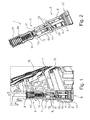
- Dabei zeigen, jeweils schematisch,
- Fig. 1
- einen erfindungsgemäßen axial durchströmbaren Ventileinsatz in einer Einbausituation in einem Filtergehäuse einer Filtereinrichtung,
- Fig. 2
- eine Detaildarstellung des erfindungsgemäßen Ventileinsatzes.
- Entsprechend den
Fig. 1 und 2 , weist ein erfindungsgemäßer axial durchströmbarer Ventileinsatz 1 ein Rücklaufsperrventil 2 sowie ein koaxial dazu angeordnetes und in Reihe geschaltetes Thermostatventil 3 auf. Das Thermostatventil 3 und das Rücklaufsperrventil 2 sind axial zueinander beabstandet im Ventileinsatz 1 angeordnet. Das Rücklaufsperrventil 2 besitzt einen federbeaufschlagten Rücklaufsperrventilkolben 4 sowie ein Rücklaufsperrventilgehäuse 5, wobei das Rücklaufsperrventilgehäuse 5 einerseits eine Führung für den Rücklaufsperrventilkolben 4 bildet und andererseits einen Ventilsitz 6 aufweist, an welchem der federbeaufschlagte Rücklaufsperrventilkolben 4 dichtend anliegt. Betrachtet man das Rücklaufsperrventil 2 in seiner Einbausituation in einem Filtergehäuse 7 einer nicht näher gezeigten Filtereinrichtung 8 gemäßFig. 1 , bspw. einem Ölfilter eines Verbrennungsmotors in einem Kraftfahrzeug, so kann man erkennen, dass der Ventileinsatz 1 in einer Leitung zwischen dem eigentlichen Filter der Filtereinrichtung 8 und einer Pumpe 9 angeordnet ist. Öffnet der Rücklaufsperrventilkolben 4, so kann dieser in Abhängigkeit der Schaltstellung des Thermostatventils 3 einen Fluidstrom zwischen einem Ölkühler 10 und der Filtereinrichtung 8 aufteilen. - Neben dem Rücklaufsperrventil 2 besitzt der erfindungsgemäße Ventileinsatz 1 noch das Thermostatventil 3, wobei ein Thermostatventilgehäuse 11 mit dem Rücklaufsperrventilgehäuse 5 über eine Clipverbindung 12 verclipst ist. Im Thermostatventilgehäuse 11 ist ein Temperaturdehnelement 13, bspw. ein Wachsdehnelement, angeordnet, das mit einem inneren, federbeaufschlagten Thermostatventilkolben 14 zusammenwirkt. Der innere Thermostatventilkolben 14 ist dabei ebenfalls federbeaufschlagt und wirkt über eine Feder 15 mit einem äußeren Thermostatventilkolben 16 zusammen. Das Temperaturdehnelement 13 sowie der innere Thermostatventilkolben 14 sind dabei miteinander verbunden, insbesondere über einen Presssitz. Dies ermöglicht es, den Ventileinsatz 1 als einteilige und dadurch leicht zu montierende Baugruppe auszubilden. Zur Montage des Ventileinsatzes 1 im Filtergehäuse 7 wird dieser lediglich in das Filtergehäuse 7 eingeschoben und zwar soweit, bis er über eine Clipsverbindung 12' mit dem Filtergehäuse 7 verrastet. Das Filtergehäuse 7 besitzt zudem einen Ventilsitz 6' für den äußeren Thermostatventilkolben 16. Am äußeren Thermostatventilkolben 16 angeordnet ist eine weitere Feder 15', die ein Rückstellen desselben und damit ein Lösen desselben vom Ventilsitz 6' unterhalb einer vordefinierten Temperatur bewirkt.
- Im Folgenden soll nun die prinzipielle Funktionsweise des erfindungsgemäßen Ventileinsatzes 1 kurz beschrieben werden: Bei abgeschaltetem Verbrennungsmotor und damit bei abgeschalteter Pumpe 9 wirkt kein Fluiddruck, insbesondere kein Öldruck, auf den Ventileinsatz 1 ein, sodass der Rücklaufsperrventilkolben 4 auf dem Ventilsitz 6 anliegt und dadurch ein ungewolltes Leerlaufen der Filtereinrichtung 8 bzw. des Ölkühlers 10 verhindert. Dies bewirkt zudem, dass kurz nach dem Starten des Verbrennungsmotors bzw. der Pumpe 9 bereits der erforderliche Öldruck vorhanden ist. Nach dem Starten des Verbrennungsmotors fördert die Pumpe 9 das zu filternde Fluid, bspw. Öl, wobei dann der Rücklaufsperrventilkolben 4 entgegen der Feder 15" verschoben und damit vom Ventilsitz 6 gelöst wird. Das zu filterende Fluid, d. h. das Öl, befindet sich dabei noch in kaltem Zustand, sodass das Temperaturdehnelement 13 im inneren Thermostatventilkolben 14 und über diesen den äußeren Thermostatventilkolben 16 noch nicht verstellt. Vielmehr befindet sich der äußere Thermostatventilkolben 16 durch die von der Feder 15' ausgeübte Federkraft noch in vom Ventilsitz 6' abgehobener Lage, sodass bei einem Starten des Verbrennungsmotors der Ventileinsatz 1 strömungsarm, d. h. mit geringem Strömungswiderstand, axial durchflossen und somit das zu filternde Fluid der Filtereinrichtung 8 zugeführt werden kann. Steigt mit fortdauernder Betriebsdauer die Temperatur des zu filternden Fluids an, so bewirkt die Dehnung des Temperaturdehnelements 13 ein Verstellen des damit gekoppelten inneren Thermostatventilkolbens 14, woraufhin dieser über die Feder 15 den äußeren Thermostatventilkolben 16 entgegen der Federkraft der Feder 15' auf den Ventilsitz 6' drückt. Beim Anliegen des äußeren Thermostatventilkolbens 16 am Ventilsitz 6' ist die direkte Verbindung zur Filtereinrichtung 8 geschlossen, woraufhin dann das zu filternde Fluid über den zum Ölkühler 10 führenden Kanal seitlich abgeleitet wird.
- Steigt die Temperatur des zu filternden Fluids weiter an, so führt dies zu einer weiteren Dehnung des Temperaturdehnelements 13, wobei dieses dann weiter und mit höherer Kraft auf den inneren Thermostatventilkolben 14 drückt. Da sich der äußere Thermostatventilkolben 16 aufgrund des Anliegens am Ventilsitz 6 nicht weiter verstellen kann, wird nun der innere Thermostatventilkolben 14 relativ zum äußeren Thermostatventilkolben 16 entgegen der Federkraft der Feder 15 verstellt. Die Feder 15 zusammen mit dem inneren Thermostatventilkolben 14 bilden somit eine Überlastsicherung, die auch bei hohen Temperaturen eine Beschädigung des Thermostatventils 3 ausschließt.
- Verringert sich die Temperatur des zu filternden Fluids, bspw. des zu filternden Öls, wieder, so zieht sich das Temperaturdehnelement 13 zusammen, woraufhin der innere Thermostatventilkolben 14 relativ zum äußeren Thermostatventilkolben 16 solange verstellt wird, bis er mit einer Kontur 17, bspw. einem Rand, an einer Gegenkontur 18 des äußeren Thermostatventilkolbens 16 anliegt und sich dadurch nicht mehr weiter verstellen kann. Bei einer weiteren Reduzierung der Temperatur bewirkt dann die Feder 15' ein sich Lösen des äußeren Thermostatventilkolbens 16 vom Ventilsitz 6', woraufhin dann wiederum die direkte Verbindung zur Filtereinrichtung 8 geöffnet wird.
- Generell weist der erfindungsgemäße Ventileinsatz 1 eine einteilige Ausführungsform auf, wodurch eine besonders einfache Montage desselben möglich ist. Durch seine axiale Durchströmbarkeit besitzt er zudem einen vergleichsweise geringen Strömungswiderstand, was vorteilhaft in Bezug auf die Leistungsaufnahme der Pumpe 9 ist. Die einzelnen Teile des Ventileinsatzes 1, insbesondere der äußere Thermostatventilkolben 16, der Rücklaufsperrventilkolben 4 bzw. das Thermostatventilgehäuse 11 und das Rücklaufsperrventilgehäuse 5 können bspw. als kostengünstige Kunststoffbauteile ausgebildet sein.
Claims (10)
- Axial durchströmbarer Ventileinsatz (1) mit einem Rücklaufsperrventil (2) und einem koaxial dazu angeordneten und in Reihe geschalteten Thermostatventil (3).
- Ventileinsatz nach Anspruch 1,
dadurch gekennzeichnet,
dass das Rücklaufsperrventil (2) einen federbeaufschlagten Rücklaufsperrventilkolben (4) und ein Rücklaufsperrventilgehäuse (5) aufweist, das einerseits eine Führung für den Rücklaufsperrventilkolben (4) bildet und andererseits einen Ventilsitz (6) aufweist. - Ventileinsatz nach Anspruch 2,
dadurch gekennzeichnet,
dass das Rücklaufsperrventilgehäuse (5) mit einem Thermostatventilgehäuse (11) über eine Clipverbindung (12) verclipst ist. - Filtereinrichtung nach Anspruch 3,
dadurch gekennzeichnet,
dass im Thermostatventilgehäuse (11) ein Temperaturdehnelement (13), insbesondere ein Wachsdehnelement, angeordnet ist, das mit einem federbaufschlagten inneren Thermostatventilkolben (14) zusammenwirkt. - Ventileinsatz nach Anspruch 4,
dadurch gekennzeichnet,
dass der innere Thermostatventilkolben (14) über eine Feder (15) mit einem äußeren Thermostatventilkolben (16) zusammenwirkt. - Ventileinsatz nach Anspruch 5,
dadurch gekennzeichnet,
dass das Temperaturdehnelement (13) und der innere Thermostatventilkolben (14) miteinander verbunden, insbesondere über einen Presssitz, miteinander verbunden sind. - Filtereinrichtung (8), insbesondere ein Ölfilter, mit einem Ventileinsatz (1) nach einem der Ansprüche 1 bis 6.
- Filtereinrichtung nach Anspruch 7,
dadurch gekennzeichnet,
dass die Filtereinrichtung (8) ein Filtergehäuse (7) aufweist, in welches der Ventileinsatz (1) einsetzbar, insbesondere einclipsbar, ist. - Filtereinrichtung nach Anspruch 8,
dadurch gekennzeichnet,
dass das Filtergehäuse (7) einen Ventilsitz (6') für den äußeren Thermostatventilkolben (16) aufweist. - Filtereinrichtung nach Anspruch 8,
dadurch gekennzeichnet,
dass der Ventileinsatz (1) in Abhängigkeit des Drucks und der Temperatur des zu filternden Fluids dieses auf ein Filter, insbesondere ein Ölfilter, und einen Kühler, insbesondere einen Ölkühler, aufteilt.
Priority Applications (1)
| Application Number | Priority Date | Filing Date | Title |
|---|---|---|---|
| PL12190485T PL2592317T3 (pl) | 2011-11-09 | 2012-10-30 | Wkład zaworu i przynależne urządzenie filtrujące |
Applications Claiming Priority (1)
| Application Number | Priority Date | Filing Date | Title |
|---|---|---|---|
| DE102011085993A DE102011085993A1 (de) | 2011-11-09 | 2011-11-09 | Ventileinsatz und zugehörige Filtereinrichtung |
Publications (2)
| Publication Number | Publication Date |
|---|---|
| EP2592317A1 true EP2592317A1 (de) | 2013-05-15 |
| EP2592317B1 EP2592317B1 (de) | 2016-12-14 |
Family
ID=47143607
Family Applications (1)
| Application Number | Title | Priority Date | Filing Date |
|---|---|---|---|
| EP12190485.8A Not-in-force EP2592317B1 (de) | 2011-11-09 | 2012-10-30 | Ventileinsatz und zugehörige Filtereinrichtung |
Country Status (4)
| Country | Link |
|---|---|
| EP (1) | EP2592317B1 (de) |
| KR (1) | KR20130051414A (de) |
| DE (1) | DE102011085993A1 (de) |
| PL (1) | PL2592317T3 (de) |
Cited By (3)
| Publication number | Priority date | Publication date | Assignee | Title |
|---|---|---|---|---|
| EP2806203A1 (de) * | 2013-05-23 | 2014-11-26 | Mahle International GmbH | Baukastensystem für einen axial durchströmbaren Ventileinsatz |
| IT201700020428A1 (it) * | 2017-02-23 | 2018-08-23 | Ufi Filters Spa | Un gruppo valvola con corpo valvola e dispositivo di comando |
| US20240044269A1 (en) * | 2020-12-21 | 2024-02-08 | Ufi Filters S.P.A. | Valve group |
Citations (5)
| Publication number | Priority date | Publication date | Assignee | Title |
|---|---|---|---|---|
| US4147180A (en) * | 1977-06-22 | 1979-04-03 | Robertshaw Controls Company | Condition responsive valve construction |
| DE3640531C1 (de) * | 1986-11-27 | 1987-09-03 | Bayerische Motoren Werke Ag | Filteranordnung zum Reinigen von fluessigen Betriebsstoffen,insbesondere des Schmieroeles von Brennkraftmaschinen |
| WO2002001061A1 (de) * | 2000-06-27 | 2002-01-03 | Filterwerk Mann+Hummel Gmbh | Flüssigkeitskreislauf |
| JP2006226468A (ja) * | 2005-02-18 | 2006-08-31 | Kuzee:Kk | 弁装置 |
| EP2080943A1 (de) * | 2008-01-18 | 2009-07-22 | Ford Global Technologies, LLC | Regelventil |
Family Cites Families (1)
| Publication number | Priority date | Publication date | Assignee | Title |
|---|---|---|---|---|
| DE60221447T2 (de) * | 2001-09-13 | 2008-04-24 | Entegris, Inc., Chaska | Trennmodul |
-
2011
- 2011-11-09 DE DE102011085993A patent/DE102011085993A1/de not_active Withdrawn
-
2012
- 2012-10-30 PL PL12190485T patent/PL2592317T3/pl unknown
- 2012-10-30 EP EP12190485.8A patent/EP2592317B1/de not_active Not-in-force
- 2012-11-07 KR KR1020120125291A patent/KR20130051414A/ko not_active Withdrawn
Patent Citations (5)
| Publication number | Priority date | Publication date | Assignee | Title |
|---|---|---|---|---|
| US4147180A (en) * | 1977-06-22 | 1979-04-03 | Robertshaw Controls Company | Condition responsive valve construction |
| DE3640531C1 (de) * | 1986-11-27 | 1987-09-03 | Bayerische Motoren Werke Ag | Filteranordnung zum Reinigen von fluessigen Betriebsstoffen,insbesondere des Schmieroeles von Brennkraftmaschinen |
| WO2002001061A1 (de) * | 2000-06-27 | 2002-01-03 | Filterwerk Mann+Hummel Gmbh | Flüssigkeitskreislauf |
| JP2006226468A (ja) * | 2005-02-18 | 2006-08-31 | Kuzee:Kk | 弁装置 |
| EP2080943A1 (de) * | 2008-01-18 | 2009-07-22 | Ford Global Technologies, LLC | Regelventil |
Cited By (7)
| Publication number | Priority date | Publication date | Assignee | Title |
|---|---|---|---|---|
| EP2806203A1 (de) * | 2013-05-23 | 2014-11-26 | Mahle International GmbH | Baukastensystem für einen axial durchströmbaren Ventileinsatz |
| CN104180027A (zh) * | 2013-05-23 | 2014-12-03 | 马勒国际有限公司 | 用于能轴向穿流的阀芯的模块化系统 |
| IT201700020428A1 (it) * | 2017-02-23 | 2018-08-23 | Ufi Filters Spa | Un gruppo valvola con corpo valvola e dispositivo di comando |
| WO2018154471A1 (en) * | 2017-02-23 | 2018-08-30 | Ufi Filters S.P.A. | A valve group with a valve body and a control device |
| CN110494633A (zh) * | 2017-02-23 | 2019-11-22 | Ufi过滤器股份公司 | 具有阀体及控制装置的阀组 |
| CN110494633B (zh) * | 2017-02-23 | 2021-06-15 | Ufi过滤器股份公司 | 具有阀体及控制装置的阀组 |
| US20240044269A1 (en) * | 2020-12-21 | 2024-02-08 | Ufi Filters S.P.A. | Valve group |
Also Published As
| Publication number | Publication date |
|---|---|
| PL2592317T3 (pl) | 2017-07-31 |
| EP2592317B1 (de) | 2016-12-14 |
| DE102011085993A1 (de) | 2013-05-16 |
| KR20130051414A (ko) | 2013-05-20 |
Similar Documents
| Publication | Publication Date | Title |
|---|---|---|
| DE202008014212U1 (de) | Wärmetauscher mit Umgehungsventil | |
| EP1814009B1 (de) | Thermostatventil zum Verbinden eines automatischen Getriebes mit einem Ölkühler | |
| EP3387225B1 (de) | Fluidversorgungssystem | |
| DE102013114335A1 (de) | Ölzuführsystem | |
| WO2018086886A1 (de) | Elektrische kühlmittelpumpe | |
| EP3338014A1 (de) | Druck- und temperaturgesteuertes ventil in einem ölkreislauf einer brennkraftmaschine | |
| EP2806203B1 (de) | Baukastensystem für einen axial durchströmbaren Ventileinsatz | |
| DE102011056774B4 (de) | Ventil für ein Fahrzeug | |
| EP2305360A1 (de) | Ölfiltermodul | |
| EP2592317B1 (de) | Ventileinsatz und zugehörige Filtereinrichtung | |
| DE102009032647A1 (de) | Kühlsystem für eine Verbrennungskraftmaschine | |
| EP2551569B1 (de) | Thermostatventil | |
| EP2080943B1 (de) | Regelventil | |
| EP3452705B1 (de) | Fluidversorgungssystem | |
| EP1835142B1 (de) | Ventilanordnung, insbesondere zur Einstellung einer Heizmittel/ Kühlmittel-Strömung in einem Kraftfahrzeug | |
| DE102010047793A1 (de) | Kraftfahrzeugkühlvorrichtung | |
| EP2626526B1 (de) | Ventileinrichtung | |
| DE102017010391A1 (de) | Ventileinrichtung für einen von Kühlmittel durchströmbaren Kühlmittelkreislauf eines Kraftwagens | |
| WO2017194602A1 (de) | Flüssigfiltermodul | |
| DE102009005595A1 (de) | Ventil für Kraftstoffanlagen | |
| WO2011047749A1 (de) | Kaltstartventil | |
| DE102010032540A1 (de) | Kühlmittelpumpe | |
| DE102016201696A1 (de) | Hydraulikventil | |
| DE102016014720A1 (de) | Ventilmodul für einen Ölkreislauf einer Verbrennungskraftmaschine | |
| DE102007055264A1 (de) | Rücklaufsperrventil |
Legal Events
| Date | Code | Title | Description |
|---|---|---|---|
| PUAI | Public reference made under article 153(3) epc to a published international application that has entered the european phase |
Free format text: ORIGINAL CODE: 0009012 |
|
| AK | Designated contracting states |
Kind code of ref document: A1 Designated state(s): AL AT BE BG CH CY CZ DE DK EE ES FI FR GB GR HR HU IE IS IT LI LT LU LV MC MK MT NL NO PL PT RO RS SE SI SK SM TR |
|
| AX | Request for extension of the european patent |
Extension state: BA ME |
|
| 17P | Request for examination filed |
Effective date: 20131029 |
|
| RBV | Designated contracting states (corrected) |
Designated state(s): AL AT BE BG CH CY CZ DE DK EE ES FI FR GB GR HR HU IE IS IT LI LT LU LV MC MK MT NL NO PL PT RO RS SE SI SK SM TR |
|
| GRAP | Despatch of communication of intention to grant a patent |
Free format text: ORIGINAL CODE: EPIDOSNIGR1 |
|
| INTG | Intention to grant announced |
Effective date: 20160705 |
|
| GRAS | Grant fee paid |
Free format text: ORIGINAL CODE: EPIDOSNIGR3 |
|
| GRAA | (expected) grant |
Free format text: ORIGINAL CODE: 0009210 |
|
| AK | Designated contracting states |
Kind code of ref document: B1 Designated state(s): AL AT BE BG CH CY CZ DE DK EE ES FI FR GB GR HR HU IE IS IT LI LT LU LV MC MK MT NL NO PL PT RO RS SE SI SK SM TR |
|
| REG | Reference to a national code |
Ref country code: GB Ref legal event code: FG4D Free format text: NOT ENGLISH |
|
| REG | Reference to a national code |
Ref country code: CH Ref legal event code: EP |
|
| REG | Reference to a national code |
Ref country code: IE Ref legal event code: FG4D Free format text: LANGUAGE OF EP DOCUMENT: GERMAN |
|
| REG | Reference to a national code |
Ref country code: AT Ref legal event code: REF Ref document number: 853898 Country of ref document: AT Kind code of ref document: T Effective date: 20170115 |
|
| REG | Reference to a national code |
Ref country code: DE Ref legal event code: R096 Ref document number: 502012009016 Country of ref document: DE |
|
| PG25 | Lapsed in a contracting state [announced via postgrant information from national office to epo] |
Ref country code: LV Free format text: LAPSE BECAUSE OF FAILURE TO SUBMIT A TRANSLATION OF THE DESCRIPTION OR TO PAY THE FEE WITHIN THE PRESCRIBED TIME-LIMIT Effective date: 20161214 |
|
| REG | Reference to a national code |
Ref country code: LT Ref legal event code: MG4D |
|
| REG | Reference to a national code |
Ref country code: NL Ref legal event code: MP Effective date: 20161214 |
|
| PG25 | Lapsed in a contracting state [announced via postgrant information from national office to epo] |
Ref country code: LT Free format text: LAPSE BECAUSE OF FAILURE TO SUBMIT A TRANSLATION OF THE DESCRIPTION OR TO PAY THE FEE WITHIN THE PRESCRIBED TIME-LIMIT Effective date: 20161214 Ref country code: SE Free format text: LAPSE BECAUSE OF FAILURE TO SUBMIT A TRANSLATION OF THE DESCRIPTION OR TO PAY THE FEE WITHIN THE PRESCRIBED TIME-LIMIT Effective date: 20161214 Ref country code: GR Free format text: LAPSE BECAUSE OF FAILURE TO SUBMIT A TRANSLATION OF THE DESCRIPTION OR TO PAY THE FEE WITHIN THE PRESCRIBED TIME-LIMIT Effective date: 20170315 Ref country code: NO Free format text: LAPSE BECAUSE OF FAILURE TO SUBMIT A TRANSLATION OF THE DESCRIPTION OR TO PAY THE FEE WITHIN THE PRESCRIBED TIME-LIMIT Effective date: 20170314 |
|
| PG25 | Lapsed in a contracting state [announced via postgrant information from national office to epo] |
Ref country code: FI Free format text: LAPSE BECAUSE OF FAILURE TO SUBMIT A TRANSLATION OF THE DESCRIPTION OR TO PAY THE FEE WITHIN THE PRESCRIBED TIME-LIMIT Effective date: 20161214 Ref country code: HR Free format text: LAPSE BECAUSE OF FAILURE TO SUBMIT A TRANSLATION OF THE DESCRIPTION OR TO PAY THE FEE WITHIN THE PRESCRIBED TIME-LIMIT Effective date: 20161214 Ref country code: RS Free format text: LAPSE BECAUSE OF FAILURE TO SUBMIT A TRANSLATION OF THE DESCRIPTION OR TO PAY THE FEE WITHIN THE PRESCRIBED TIME-LIMIT Effective date: 20161214 |
|
| PG25 | Lapsed in a contracting state [announced via postgrant information from national office to epo] |
Ref country code: NL Free format text: LAPSE BECAUSE OF FAILURE TO SUBMIT A TRANSLATION OF THE DESCRIPTION OR TO PAY THE FEE WITHIN THE PRESCRIBED TIME-LIMIT Effective date: 20161214 |
|
| PG25 | Lapsed in a contracting state [announced via postgrant information from national office to epo] |
Ref country code: IS Free format text: LAPSE BECAUSE OF FAILURE TO SUBMIT A TRANSLATION OF THE DESCRIPTION OR TO PAY THE FEE WITHIN THE PRESCRIBED TIME-LIMIT Effective date: 20170414 Ref country code: EE Free format text: LAPSE BECAUSE OF FAILURE TO SUBMIT A TRANSLATION OF THE DESCRIPTION OR TO PAY THE FEE WITHIN THE PRESCRIBED TIME-LIMIT Effective date: 20161214 Ref country code: CZ Free format text: LAPSE BECAUSE OF FAILURE TO SUBMIT A TRANSLATION OF THE DESCRIPTION OR TO PAY THE FEE WITHIN THE PRESCRIBED TIME-LIMIT Effective date: 20161214 Ref country code: RO Free format text: LAPSE BECAUSE OF FAILURE TO SUBMIT A TRANSLATION OF THE DESCRIPTION OR TO PAY THE FEE WITHIN THE PRESCRIBED TIME-LIMIT Effective date: 20161214 Ref country code: SK Free format text: LAPSE BECAUSE OF FAILURE TO SUBMIT A TRANSLATION OF THE DESCRIPTION OR TO PAY THE FEE WITHIN THE PRESCRIBED TIME-LIMIT Effective date: 20161214 |
|
| PG25 | Lapsed in a contracting state [announced via postgrant information from national office to epo] |
Ref country code: PT Free format text: LAPSE BECAUSE OF FAILURE TO SUBMIT A TRANSLATION OF THE DESCRIPTION OR TO PAY THE FEE WITHIN THE PRESCRIBED TIME-LIMIT Effective date: 20170414 Ref country code: SM Free format text: LAPSE BECAUSE OF FAILURE TO SUBMIT A TRANSLATION OF THE DESCRIPTION OR TO PAY THE FEE WITHIN THE PRESCRIBED TIME-LIMIT Effective date: 20161214 Ref country code: BG Free format text: LAPSE BECAUSE OF FAILURE TO SUBMIT A TRANSLATION OF THE DESCRIPTION OR TO PAY THE FEE WITHIN THE PRESCRIBED TIME-LIMIT Effective date: 20170314 Ref country code: ES Free format text: LAPSE BECAUSE OF FAILURE TO SUBMIT A TRANSLATION OF THE DESCRIPTION OR TO PAY THE FEE WITHIN THE PRESCRIBED TIME-LIMIT Effective date: 20161214 |
|
| REG | Reference to a national code |
Ref country code: DE Ref legal event code: R097 Ref document number: 502012009016 Country of ref document: DE |
|
| PLBE | No opposition filed within time limit |
Free format text: ORIGINAL CODE: 0009261 |
|
| STAA | Information on the status of an ep patent application or granted ep patent |
Free format text: STATUS: NO OPPOSITION FILED WITHIN TIME LIMIT |
|
| REG | Reference to a national code |
Ref country code: FR Ref legal event code: PLFP Year of fee payment: 6 |
|
| 26N | No opposition filed |
Effective date: 20170915 |
|
| PG25 | Lapsed in a contracting state [announced via postgrant information from national office to epo] |
Ref country code: DK Free format text: LAPSE BECAUSE OF FAILURE TO SUBMIT A TRANSLATION OF THE DESCRIPTION OR TO PAY THE FEE WITHIN THE PRESCRIBED TIME-LIMIT Effective date: 20161214 |
|
| PG25 | Lapsed in a contracting state [announced via postgrant information from national office to epo] |
Ref country code: SI Free format text: LAPSE BECAUSE OF FAILURE TO SUBMIT A TRANSLATION OF THE DESCRIPTION OR TO PAY THE FEE WITHIN THE PRESCRIBED TIME-LIMIT Effective date: 20161214 |
|
| PG25 | Lapsed in a contracting state [announced via postgrant information from national office to epo] |
Ref country code: MC Free format text: LAPSE BECAUSE OF FAILURE TO SUBMIT A TRANSLATION OF THE DESCRIPTION OR TO PAY THE FEE WITHIN THE PRESCRIBED TIME-LIMIT Effective date: 20161214 |
|
| REG | Reference to a national code |
Ref country code: CH Ref legal event code: PL |
|
| GBPC | Gb: european patent ceased through non-payment of renewal fee |
Effective date: 20171030 |
|
| REG | Reference to a national code |
Ref country code: IE Ref legal event code: MM4A |
|
| PG25 | Lapsed in a contracting state [announced via postgrant information from national office to epo] |
Ref country code: GB Free format text: LAPSE BECAUSE OF NON-PAYMENT OF DUE FEES Effective date: 20171030 Ref country code: CH Free format text: LAPSE BECAUSE OF NON-PAYMENT OF DUE FEES Effective date: 20171031 Ref country code: LU Free format text: LAPSE BECAUSE OF NON-PAYMENT OF DUE FEES Effective date: 20171030 Ref country code: LI Free format text: LAPSE BECAUSE OF NON-PAYMENT OF DUE FEES Effective date: 20171031 |
|
| REG | Reference to a national code |
Ref country code: BE Ref legal event code: MM Effective date: 20171031 |
|
| PG25 | Lapsed in a contracting state [announced via postgrant information from national office to epo] |
Ref country code: BE Free format text: LAPSE BECAUSE OF NON-PAYMENT OF DUE FEES Effective date: 20171031 |
|
| PG25 | Lapsed in a contracting state [announced via postgrant information from national office to epo] |
Ref country code: MT Free format text: LAPSE BECAUSE OF FAILURE TO SUBMIT A TRANSLATION OF THE DESCRIPTION OR TO PAY THE FEE WITHIN THE PRESCRIBED TIME-LIMIT Effective date: 20161214 |
|
| REG | Reference to a national code |
Ref country code: FR Ref legal event code: PLFP Year of fee payment: 7 |
|
| PG25 | Lapsed in a contracting state [announced via postgrant information from national office to epo] |
Ref country code: IE Free format text: LAPSE BECAUSE OF NON-PAYMENT OF DUE FEES Effective date: 20171030 |
|
| REG | Reference to a national code |
Ref country code: AT Ref legal event code: MM01 Ref document number: 853898 Country of ref document: AT Kind code of ref document: T Effective date: 20171030 |
|
| PG25 | Lapsed in a contracting state [announced via postgrant information from national office to epo] |
Ref country code: AT Free format text: LAPSE BECAUSE OF NON-PAYMENT OF DUE FEES Effective date: 20171030 |
|
| PGFP | Annual fee paid to national office [announced via postgrant information from national office to epo] |
Ref country code: PL Payment date: 20181018 Year of fee payment: 7 |
|
| PGFP | Annual fee paid to national office [announced via postgrant information from national office to epo] |
Ref country code: FR Payment date: 20181030 Year of fee payment: 7 Ref country code: IT Payment date: 20181024 Year of fee payment: 7 |
|
| PG25 | Lapsed in a contracting state [announced via postgrant information from national office to epo] |
Ref country code: HU Free format text: LAPSE BECAUSE OF FAILURE TO SUBMIT A TRANSLATION OF THE DESCRIPTION OR TO PAY THE FEE WITHIN THE PRESCRIBED TIME-LIMIT; INVALID AB INITIO Effective date: 20121030 |
|
| PG25 | Lapsed in a contracting state [announced via postgrant information from national office to epo] |
Ref country code: CY Free format text: LAPSE BECAUSE OF NON-PAYMENT OF DUE FEES Effective date: 20161214 |
|
| PG25 | Lapsed in a contracting state [announced via postgrant information from national office to epo] |
Ref country code: MK Free format text: LAPSE BECAUSE OF FAILURE TO SUBMIT A TRANSLATION OF THE DESCRIPTION OR TO PAY THE FEE WITHIN THE PRESCRIBED TIME-LIMIT Effective date: 20161214 |
|
| PG25 | Lapsed in a contracting state [announced via postgrant information from national office to epo] |
Ref country code: TR Free format text: LAPSE BECAUSE OF FAILURE TO SUBMIT A TRANSLATION OF THE DESCRIPTION OR TO PAY THE FEE WITHIN THE PRESCRIBED TIME-LIMIT Effective date: 20161214 |
|
| PG25 | Lapsed in a contracting state [announced via postgrant information from national office to epo] |
Ref country code: AL Free format text: LAPSE BECAUSE OF FAILURE TO SUBMIT A TRANSLATION OF THE DESCRIPTION OR TO PAY THE FEE WITHIN THE PRESCRIBED TIME-LIMIT Effective date: 20161214 |
|
| PG25 | Lapsed in a contracting state [announced via postgrant information from national office to epo] |
Ref country code: FR Free format text: LAPSE BECAUSE OF NON-PAYMENT OF DUE FEES Effective date: 20191031 Ref country code: IT Free format text: LAPSE BECAUSE OF NON-PAYMENT OF DUE FEES Effective date: 20191030 |
|
| PG25 | Lapsed in a contracting state [announced via postgrant information from national office to epo] |
Ref country code: PL Free format text: LAPSE BECAUSE OF NON-PAYMENT OF DUE FEES Effective date: 20191030 |
|
| PGFP | Annual fee paid to national office [announced via postgrant information from national office to epo] |
Ref country code: DE Payment date: 20231020 Year of fee payment: 12 |
|
| REG | Reference to a national code |
Ref country code: DE Ref legal event code: R119 Ref document number: 502012009016 Country of ref document: DE |
|
| PG25 | Lapsed in a contracting state [announced via postgrant information from national office to epo] |
Ref country code: DE Free format text: LAPSE BECAUSE OF NON-PAYMENT OF DUE FEES Effective date: 20250501 |