EP2592287B1 - Arbre télescopique avec élément de traction - Google Patents
Arbre télescopique avec élément de traction Download PDFInfo
- Publication number
- EP2592287B1 EP2592287B1 EP12182453.6A EP12182453A EP2592287B1 EP 2592287 B1 EP2592287 B1 EP 2592287B1 EP 12182453 A EP12182453 A EP 12182453A EP 2592287 B1 EP2592287 B1 EP 2592287B1
- Authority
- EP
- European Patent Office
- Prior art keywords
- profile tube
- telescopic shaft
- axial
- tube
- connection element
- Prior art date
- Legal status (The legal status is an assumption and is not a legal conclusion. Google has not performed a legal analysis and makes no representation as to the accuracy of the status listed.)
- Active
Links
- 238000006073 displacement reaction Methods 0.000 claims description 3
- 230000001419 dependent effect Effects 0.000 claims 2
- 230000001681 protective effect Effects 0.000 description 7
- 238000005553 drilling Methods 0.000 description 4
- 238000004519 manufacturing process Methods 0.000 description 3
- 210000002445 nipple Anatomy 0.000 description 3
- 230000008878 coupling Effects 0.000 description 2
- 238000010168 coupling process Methods 0.000 description 2
- 238000005859 coupling reaction Methods 0.000 description 2
- 238000005516 engineering process Methods 0.000 description 2
- 239000004519 grease Substances 0.000 description 2
- 229910000831 Steel Inorganic materials 0.000 description 1
- 230000006978 adaptation Effects 0.000 description 1
- 230000037431 insertion Effects 0.000 description 1
- 238000003780 insertion Methods 0.000 description 1
- 230000001050 lubricating effect Effects 0.000 description 1
- 238000005461 lubrication Methods 0.000 description 1
- 230000002093 peripheral effect Effects 0.000 description 1
- 239000010959 steel Substances 0.000 description 1
Images


Classifications
-
- F—MECHANICAL ENGINEERING; LIGHTING; HEATING; WEAPONS; BLASTING
- F16—ENGINEERING ELEMENTS AND UNITS; GENERAL MEASURES FOR PRODUCING AND MAINTAINING EFFECTIVE FUNCTIONING OF MACHINES OR INSTALLATIONS; THERMAL INSULATION IN GENERAL
- F16C—SHAFTS; FLEXIBLE SHAFTS; ELEMENTS OR CRANKSHAFT MECHANISMS; ROTARY BODIES OTHER THAN GEARING ELEMENTS; BEARINGS
- F16C3/00—Shafts; Axles; Cranks; Eccentrics
- F16C3/02—Shafts; Axles
- F16C3/03—Shafts; Axles telescopic
-
- F—MECHANICAL ENGINEERING; LIGHTING; HEATING; WEAPONS; BLASTING
- F16—ENGINEERING ELEMENTS AND UNITS; GENERAL MEASURES FOR PRODUCING AND MAINTAINING EFFECTIVE FUNCTIONING OF MACHINES OR INSTALLATIONS; THERMAL INSULATION IN GENERAL
- F16D—COUPLINGS FOR TRANSMITTING ROTATION; CLUTCHES; BRAKES
- F16D3/00—Yielding couplings, i.e. with means permitting movement between the connected parts during the drive
- F16D3/02—Yielding couplings, i.e. with means permitting movement between the connected parts during the drive adapted to specific functions
- F16D3/06—Yielding couplings, i.e. with means permitting movement between the connected parts during the drive adapted to specific functions specially adapted to allow axial displacement
Definitions
- the invention relates to a telescopic shaft for transmitting torques, comprising an inner profile tube, a middle profile tube and an outer profile tube, which are arranged to change the length displaceable to each other, wherein a tension member is held axially immovable in the middle profile tube.
- Multipart telescopic waves are known in the art. These pose the problem, as in an extract of the inner profile tube relative to the middle profile tube, the middle profile tube, after the inner profile tube has been extended a certain distance relative to this, can be moved to pull off the outer profile tube.
- a pull wire can be used, which is fastened with its one end to an axial end of the inner profile tube, is passed therethrough and is fastened with its other end to an axial end of the middle profile tube.
- the telescopic shaft of the pull wire loosely in the inner profile tube, i. its length is greater than the axial distance of the fasteners on the respective profile tubes.
- the inner profile tube can be pulled out to a certain extent relative to the middle profile tube before the pull wire is pulled taut and pulls the middle profile tube.
- the problem with this coupling is the lack of robustness of the puller wire, which no longer withstands the loads occurring after a certain period of use.
- a telescopic shaft with an outer and an inner profile tube known.
- an inner tie rod and an outer tie rods are arranged, which are releasably connected in each case via locking body to one of the profile tubes.
- the inner tie rod has diametrically opposite Longitudinal slots in which a catch bolt is guided, which is connected to the outer tie rod.
- the catch bolt passes through the longitudinal slots when the telescopic shaft is pulled apart. Further pulling apart is possible by moving the locking body between the tie rods and the respective profile tube in an extended detent position. In the extended state, the telescopic shaft can not transmit torque.
- Object of the present invention is to provide a telescopic shaft, which can transmit torque in the extended state and the coupling of the profile tubes is robust in terms of the loads occurring.
- a telescopic shaft for transmitting torque comprising an inner profile tube, a middle profile tube and an outer profile tube, which are arranged displaceable to each other to change the length, with a tension element is held axially immovable with at least one axial slot in the middle profile tube and wherein engagement means are connected to the inner profile tube and engage the engaging means in the at least one axial slot of the tension member for limiting a displacement between the inner profile tube and the tension element.
- the advantage of this embodiment according to the invention is that a robust and resilient connection between the inner and the middle profile tube is achieved by the attachment of the tension member to its one side on the middle profile tube and by the engagement of the engagement means of the inner profile tube in the slot of the tension element ,
- a further advantage is that the production of a slot manufacturing technology is easy to implement, yet the tension element is not weakened to a significant extent with respect to the critical tensile loads. Furthermore, for the preparation of the tension element on all sides available standard or meterware can be used.
- the tension element preferably comprises a tube with a round cross section.
- a low weight of the tension member over a full cross-section is thus guaranteed.
- a round cross-section is advantageous, since thus no tailor-made adaptation to the profiling of the profile tubes must be done.
- two opposite axial axial slots are provided on both sides.
- the advantage here is the rotational symmetry of the tension element.
- the engagement means engage diametrically through the axial slots. This ensures in an advantageous manner that the engagement means can be connected to both axial sides of this passage through the tension member with the inner profile tube or attached thereto.
- the tension element may comprise a tube or be made of a tube, in the wall of which at least one elongated hole is introduced.
- the tension member may comprise two axially aligned tie rods arranged parallel to each other, e.g. made of flat steel, which are connected to each other at their axial ends via end members forming a pipe section.
- the end elements may themselves be tubular, which are connected to the ends of the tie rods, and / or be designed cup-shaped to form a tubular portion together with the tie rods.
- the engagement means comprise a first dowel pin.
- the tension element is held over a second tension pin relative to the middle profile tube.
- the second tensioning pin is seated in tensioning pin bores in each case of the middle profile pipe and of the tensioning element, which is preferably tubular. Such a connection is easy to represent in terms of manufacturing technology.
- the inner profile tube is slidably seated between the tension member and the middle profile tube.
- a first radial axis of the clamping pin bore extending in the tension element deviating from a right angle to an axial plane passing through the at least one axial slot and a longitudinal axis of the Telescope shaft is clamped.
- a second radial axis of the clamping pin bore extends in the middle profile tube deviating from a right angle to an axial plane which is spanned by the at least one axial slot and a longitudinal axis of the telescopic shaft.
- the first and the second radial axis of the clamping pin bores lie on one another.
- a propeller shaft with a telescopic shaft according to the invention, wherein a first joint with the inner profile tube is rotatably connected and a second joint with the outer profile tube is rotatably connected.
- the joints are each at universal joints.
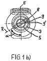
- FIG. 1 is a propeller shaft 31 shown with universal joints 11, 12 and a three-part telescoping telescopic shaft 1 in the fully inserted state.
- the telescopic shaft 1 consists of an inner profile tube 2, which is rotatably connected at its one axial end 17 with the first universal joint 11, an outer profile tube 4 which is rotatably connected at its one axial end 19 to the second universal joint 12, and a middle Profile tube 3.
- the profile tubes 2, 3, 4 are telescoped into one another, the middle profile tube 3 being arranged between the inner profile tube 2 and the outer profile tube 4.
- each Protective tube 13, 14 is attached to the outer or inner profile tube 4, 2 in the region of the respective universal joint 11, 12.
- the protective tubes 13, 14 are secured with chains 15 against rotation.
- a tension element in the form of a pull rod 5 is arranged, which comprises a tube 10.
- the pull rod 5 projects axially beyond the axial end 18 of the inner profile tube 2, which faces away from the universal joint 11 fastened to the inner profile tube 2.
- the pull rod 5 is held by means of a second clamping pin 8 on the middle profile tube 3.
- the second clamping pin 8 is seated in clamping hole bores 9, 9 'of the middle profile tube 3 and the tie rod 5, as in the Figure 1 b can be seen.
- the Spannlochbohronne 9 have from the axial end 21 of the central profile tube 3 about a distance of 10 mm and the Spannlochbohronne 9 'have from the axial end 20 of the tie rod 5 about a distance of 10 mm.
- the second clamping pin 8 is seated at an angle ⁇ of 60 ° in the middle profile tube 3 and the pull rod 5 in the clamping hole bores 9, 9 'relative to an axial plane E.
- Other angles ⁇ may also be provided.
- the pull rod 5 has a round cross-section.
- the pull rod 5 has two diametrically opposite axial slots 6, 6 ', of which in the FIG. 1a only the slot 6 can be seen. From the axial end 20 of the pull rod 5, the axial slots 6, 6 'have a distance of about 25 mm. Through the two axial slots 6, 6 'engage engagement means in the form of a first clamping pin 7 radially therethrough. The first clamping pin 7 is held in clamping pin holes 16 of the inner profile tube 2.
- the Spannjanbohrept 16 have from the axial end 18 of the inner profile tube 2 about a distance of 15 mm.
- the inner profile tube 2 is first pulled out relative to the middle profile tube 3 and connected to the middle profile tube 3 pull rod 5. In this case, passes through the first dowel pin 7, which is connected to the inner profile tube 2, the axial slots 6, 6 'of the tie rod 5. At the moment in which the first dowel pin 7 has passed through the axial slots completely, i. strikes, in the extension direction on the first clamping pin 7 and the tie rod 5 is a positive connection between the inner profile tube 2 and the middle profile tube 3, so that a further extension movement of the telescopic shaft 1 takes place via an extending the middle profile tube 3 relative to the outer profile tube 4.
- the displacement between the inner profile tube 2 and the tie rod 5 is limited.
- the insertion of the telescopic shaft 1 takes place in the reverse order or alternatively, by first the inner profile tube 2 with respect to the pull rod 5 einschiebt, wherein the first clamping pin 7, the axial slots 6, 6 'passes, and then the middle profile tube 3 is taken from the pull rod 5 and pushes against the outer profile tube 4.
- a bore is provided on the circumference of the sleeve 30 of the protective tube 14.
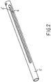
- FIG. 2 shows an example of a tension element 5 with the two axial slots 6, 6 '.
- the tension element according to FIG. 3 be constructed, this is not made of a tube, are introduced into the slots.
- the tension element according to FIG. 3 it is a built-in tension element with two rectangular cross-section tie rods 32, 33 which are parallel to each other. At one of their ends, the tie rods 32, 33 are welded to a tubular end member 34.
- the end element 34 at one of its ends on the front side two slots 35 into which the ends of the tie rods 32, 33 are inserted.
- the slots 35 extend over a portion of the length of the end member 34 and penetrate the entire wall thickness thereof.
- Such a closure element may also be provided at the other ends of the tie rods 32, 33.
- two cup-shaped end portions 36, 37 are provided which are connected to the tie rods 32, 33 so as to collectively form a tubular end member. This type of connection can also be provided instead of the end element 34 at the other end.
Landscapes
- Engineering & Computer Science (AREA)
- General Engineering & Computer Science (AREA)
- Mechanical Engineering (AREA)
- Ocean & Marine Engineering (AREA)
- Mutual Connection Of Rods And Tubes (AREA)
- Shafts, Cranks, Connecting Bars, And Related Bearings (AREA)
- Steering Controls (AREA)
Claims (12)
- Arbre télescopique (1), destiné à transmettre des couples de rotation, comprenant un tube profilé (2) interne, un tube profilé (3) central et un tube profilé (4) externe, qui pour faire varier la longueur sont placés en étant déplaçables l'un par rapport à l'autre, des moyens d'engagement (7) étant assemblés avec le tube profilé (2) interne, caractérisé
en ce qu'un élément de traction (5) avec au moins un trou oblong (6) axial est maintenu en étant indéplaçable en direction axiale dans le tube profilé (3) central et pour délimiter une course de déplacement entre le tube profilé (2) interne et l'élément de traction (5), les moyens d'engagement (7) s'engagent dans l'au moins un trou oblong (6) axial de l'élément de traction (5). - Arbre télescopique (1) selon la revendication 1,
caractérisé en ce que deux trous oblongs (6, 6') axiaux opposés de part et d'autre sont prévus. - Arbre télescopique (1) selon la revendication 2,
caractérisé en ce que les moyens d'engagement (7) traversent diamétralement les trous oblongs (6, 6') axiaux. - Arbre télescopique (1) selon l'une quelconque des revendications 1 à 3,
caractérisé en ce que l'élément de traction (5) comprend un tube (10) dans les parois duquel est ménagé l'au moins un trou oblong. - Arbre télescopique () selon l'une quelconque des revendications 1 à 3,
caractérisé en ce que
l'élément de traction (5) comprend deux barres de traction (32, 33) orientées en direction axiale, placées à la parallèle l'une de l'autre, qui sur leurs extrémités axiales sont assemblées l'une avec l'autre, par l'intermédiaire d'éléments de terminaison (34), en formant un tronçon de tube. - Arbre télescopique (1) selon l'une quelconque des revendications 1 à 5,
caractérisé en ce que les moyens d'engagement comprennent une première goupille de serrage (7) ; - Arbre télescopique (1) selon l'une quelconque des revendications 1 à 6,
caractérisé en ce que l'élément de traction (5) est maintenu par l'intermédiaire d'une deuxième goupille de serrage (8) par rapport au tube profilé (3) central. - Arbre télescopique (1) selon la revendication 7,
caractérisé en ce que la deuxième goupille de serrage (8) est logée dans des perçages (9, 9') pour goupille de serrage respectivement du tube profilé (3) central et de l'élément de traction (5). - Arbre télescopique (1) selon l'une quelconque des revendications 1 à 8,
caractérisé en ce que le profilé interne (2) est logé en étant déplaçable entre l'élément de traction (5) et le tube profilé (3) central. - Arbre télescopique (1) selon la revendication 8 ou la revendication 9,
caractérisé en ce qu'un premier axe radial (R) du perçage (9') pour goupille de serrage s'écoule dans l'élément de traction (5) en se différenciant d'un angle droit par rapport au plan axial, qui est défini par l'au moins un trou oblong (6) axial et un axe longitudinal (A) de l'arbre télescopique (1). - Arbre télescopique (1) selon la revendication 8 ou l'une quelconque des revendications 9 et 10, si elles dépendent de la revendication 8,
caractérisé en ce qu'un deuxième axe radial (R) du perçage (9) pour goupille de serrage s'écoule dans le tube profilé (3) central en se différenciant d'un angle droit par rapport à un plan axial (E), qui est défini par l'au moins un trou oblong (6) axial et un axe longitudinal (A) de l'arbre télescopique (1). - Arbre articulé (31) avec un arbre télescopique (1) selon l'une quelconque des revendications précédentes, une première articulation (11) étant assemblée de manière solidaire en rotation avec le tube profilé (2) interne et une deuxième articulation (12) étant assemblée de manière solidaire en rotation avec le tube profilé (4) externe.
Applications Claiming Priority (1)
| Application Number | Priority Date | Filing Date | Title |
|---|---|---|---|
| DE102011055169A DE102011055169B3 (de) | 2011-11-09 | 2011-11-09 | Teleskopwelle mit Zugelement |
Publications (2)
| Publication Number | Publication Date |
|---|---|
| EP2592287A1 EP2592287A1 (fr) | 2013-05-15 |
| EP2592287B1 true EP2592287B1 (fr) | 2017-03-29 |
Family
ID=46801340
Family Applications (1)
| Application Number | Title | Priority Date | Filing Date |
|---|---|---|---|
| EP12182453.6A Active EP2592287B1 (fr) | 2011-11-09 | 2012-08-30 | Arbre télescopique avec élément de traction |
Country Status (3)
| Country | Link |
|---|---|
| US (1) | US8870667B2 (fr) |
| EP (1) | EP2592287B1 (fr) |
| DE (1) | DE102011055169B3 (fr) |
Families Citing this family (4)
| Publication number | Priority date | Publication date | Assignee | Title |
|---|---|---|---|---|
| US20180065465A1 (en) | 2015-08-23 | 2018-03-08 | Arctic Cat Inc. | Off-Road Recreational Vehicle |
| US20170136874A1 (en) | 2015-08-23 | 2017-05-18 | Brian Harris | Off road vehicle |
| US11028883B2 (en) | 2017-11-13 | 2021-06-08 | Arctic Cat Inc. | Off-road recreational vehicle |
| US11712925B2 (en) | 2019-07-01 | 2023-08-01 | Textron Inc. | Axial plunging half-shaft assembly |
Citations (1)
| Publication number | Priority date | Publication date | Assignee | Title |
|---|---|---|---|---|
| US73914A (en) * | 1868-01-28 | Improvement in harvesters |
Family Cites Families (9)
| Publication number | Priority date | Publication date | Assignee | Title |
|---|---|---|---|---|
| US1791001A (en) * | 1931-02-03 | Steering-wheel post | ||
| US768186A (en) * | 1903-03-25 | 1904-08-23 | Robert A Lachmann | Drill-sleeve. |
| US1278459A (en) * | 1918-04-06 | 1918-09-10 | Guy V Hale | Shaft-coupling. |
| US2385608A (en) * | 1942-06-03 | 1945-09-25 | Castagna James | Curtain and drapery rod |
| DE2952029A1 (de) * | 1979-12-22 | 1981-07-02 | Zahnradfabrik Friedrichshafen Ag, 7990 Friedrichshafen | Teleskopspindel |
| DE3334709C2 (de) * | 1983-09-24 | 1985-07-25 | Jean Walterscheid Gmbh, 5204 Lohmar | Teleskopwelle |
| FR2750750B1 (fr) * | 1996-07-04 | 1998-11-06 | Guerineau Philippe | Dispositif de securite pour desolidariser un arbre mene telescopique, notamment d'une prise de force |
| US7207890B2 (en) * | 2004-11-03 | 2007-04-24 | Cnh America Llc | Tubular telescoping drive shaft |
| JP2007247846A (ja) * | 2006-03-17 | 2007-09-27 | Jtekt Corp | 伸縮自在シャフト |
-
2011
- 2011-11-09 DE DE102011055169A patent/DE102011055169B3/de not_active Expired - Fee Related
-
2012
- 2012-08-30 EP EP12182453.6A patent/EP2592287B1/fr active Active
- 2012-11-07 US US13/670,724 patent/US8870667B2/en active Active
Patent Citations (1)
| Publication number | Priority date | Publication date | Assignee | Title |
|---|---|---|---|---|
| US73914A (en) * | 1868-01-28 | Improvement in harvesters |
Also Published As
| Publication number | Publication date |
|---|---|
| EP2592287A1 (fr) | 2013-05-15 |
| DE102011055169B3 (de) | 2013-03-21 |
| US20130116057A1 (en) | 2013-05-09 |
| US8870667B2 (en) | 2014-10-28 |
Similar Documents
| Publication | Publication Date | Title |
|---|---|---|
| DE3334709C2 (de) | Teleskopwelle | |
| DE102005034063B3 (de) | Vorrichtung zum Verschließen von Gebäudeöffnungen | |
| EP2744626B1 (fr) | Dispositif de compression | |
| DE19911111C1 (de) | Anordnung mit einem Gleichlauffestgelenk und einer Verbindungswelle | |
| DE202014101515U1 (de) | Klappfahrradspezifische zweifache Schnelllöseeinheit | |
| EP2895769B1 (fr) | Élément de liaison de chaîne à entretoise de blocage | |
| EP2592287B1 (fr) | Arbre télescopique avec élément de traction | |
| DE1784533A1 (de) | Vorzufertigendes Bauelement | |
| DE3221007A1 (de) | Schutzvorrichtung fuer kardanwellen | |
| DE102008013227B4 (de) | Verfahren zum Herstellen einer Verbindung eines Getriebebauteils | |
| WO2018224417A1 (fr) | Dispositif de serrage pour un bâton ajustable en longueur | |
| DE2803822A1 (de) | Dreiteilige auseinanderziehbare teleskopwelle zur uebertragung von drehmomenten | |
| DE102007036554B4 (de) | Deckel-Lager-Anordnung und Verfahren zum Montieren einer Aktuatorwelle | |
| EP3227578A1 (fr) | Arbre de transmission, en particulier arbre à croisillon | |
| DE102016007495B4 (de) | Gleichlaufgelenk mit integralem Gelenkinnenteil und Verfahren zur Herstellung eines solchen Gleichlaufgelenks | |
| EP1956252B1 (fr) | Unité de déplacement longitudinal pour arbres de transmission | |
| DE10007773A1 (de) | Kran mit einem Teleskopausleger | |
| EP2706276B1 (fr) | Tube renforcé sur la paroi intérieure et son procédé de fabrication | |
| DE202011106767U1 (de) | Ecklager | |
| EP2605943B1 (fr) | Dispositif de support pour semi-remorque, comprenant un mécanisme à broche doté d'une broche en plusieurs parties, et semi-remorque comprenant un tel dispositif de support | |
| DE2619830B2 (de) | Abschleppstange für Kraftfahrzeuge | |
| DE102013110983A1 (de) | Verbindungssystem | |
| AT525434B1 (de) | Teleskop- und/oder Faltstock | |
| DE102013016982B4 (de) | Klappmechanismus | |
| EP1055830B1 (fr) | Arbre articulé |
Legal Events
| Date | Code | Title | Description |
|---|---|---|---|
| PUAI | Public reference made under article 153(3) epc to a published international application that has entered the european phase |
Free format text: ORIGINAL CODE: 0009012 |
|
| AK | Designated contracting states |
Kind code of ref document: A1 Designated state(s): AL AT BE BG CH CY CZ DE DK EE ES FI FR GB GR HR HU IE IS IT LI LT LU LV MC MK MT NL NO PL PT RO RS SE SI SK SM TR |
|
| AX | Request for extension of the european patent |
Extension state: BA ME |
|
| 17P | Request for examination filed |
Effective date: 20131016 |
|
| RBV | Designated contracting states (corrected) |
Designated state(s): AL AT BE BG CH CY CZ DE DK EE ES FI FR GB GR HR HU IE IS IT LI LT LU LV MC MK MT NL NO PL PT RO RS SE SI SK SM TR |
|
| 17Q | First examination report despatched |
Effective date: 20140317 |
|
| GRAJ | Information related to disapproval of communication of intention to grant by the applicant or resumption of examination proceedings by the epo deleted |
Free format text: ORIGINAL CODE: EPIDOSDIGR1 |
|
| GRAP | Despatch of communication of intention to grant a patent |
Free format text: ORIGINAL CODE: EPIDOSNIGR1 |
|
| GRAP | Despatch of communication of intention to grant a patent |
Free format text: ORIGINAL CODE: EPIDOSNIGR1 |
|
| INTG | Intention to grant announced |
Effective date: 20161011 |
|
| GRAJ | Information related to disapproval of communication of intention to grant by the applicant or resumption of examination proceedings by the epo deleted |
Free format text: ORIGINAL CODE: EPIDOSDIGR1 |
|
| GRAR | Information related to intention to grant a patent recorded |
Free format text: ORIGINAL CODE: EPIDOSNIGR71 |
|
| GRAS | Grant fee paid |
Free format text: ORIGINAL CODE: EPIDOSNIGR3 |
|
| GRAA | (expected) grant |
Free format text: ORIGINAL CODE: 0009210 |
|
| INTC | Intention to grant announced (deleted) | ||
| AK | Designated contracting states |
Kind code of ref document: B1 Designated state(s): AL AT BE BG CH CY CZ DE DK EE ES FI FR GB GR HR HU IE IS IT LI LT LU LV MC MK MT NL NO PL PT RO RS SE SI SK SM TR |
|
| INTG | Intention to grant announced |
Effective date: 20170217 |
|
| REG | Reference to a national code |
Ref country code: GB Ref legal event code: FG4D Free format text: NOT ENGLISH |
|
| REG | Reference to a national code |
Ref country code: CH Ref legal event code: EP |
|
| REG | Reference to a national code |
Ref country code: AT Ref legal event code: REF Ref document number: 880069 Country of ref document: AT Kind code of ref document: T Effective date: 20170415 |
|
| REG | Reference to a national code |
Ref country code: IE Ref legal event code: FG4D Free format text: LANGUAGE OF EP DOCUMENT: GERMAN |
|
| REG | Reference to a national code |
Ref country code: DE Ref legal event code: R096 Ref document number: 502012009891 Country of ref document: DE |
|
| REG | Reference to a national code |
Ref country code: NL Ref legal event code: FP |
|
| PG25 | Lapsed in a contracting state [announced via postgrant information from national office to epo] |
Ref country code: LT Free format text: LAPSE BECAUSE OF FAILURE TO SUBMIT A TRANSLATION OF THE DESCRIPTION OR TO PAY THE FEE WITHIN THE PRESCRIBED TIME-LIMIT Effective date: 20170329 Ref country code: FI Free format text: LAPSE BECAUSE OF FAILURE TO SUBMIT A TRANSLATION OF THE DESCRIPTION OR TO PAY THE FEE WITHIN THE PRESCRIBED TIME-LIMIT Effective date: 20170329 Ref country code: GR Free format text: LAPSE BECAUSE OF FAILURE TO SUBMIT A TRANSLATION OF THE DESCRIPTION OR TO PAY THE FEE WITHIN THE PRESCRIBED TIME-LIMIT Effective date: 20170630 Ref country code: HR Free format text: LAPSE BECAUSE OF FAILURE TO SUBMIT A TRANSLATION OF THE DESCRIPTION OR TO PAY THE FEE WITHIN THE PRESCRIBED TIME-LIMIT Effective date: 20170329 Ref country code: NO Free format text: LAPSE BECAUSE OF FAILURE TO SUBMIT A TRANSLATION OF THE DESCRIPTION OR TO PAY THE FEE WITHIN THE PRESCRIBED TIME-LIMIT Effective date: 20170629 |
|
| REG | Reference to a national code |
Ref country code: FR Ref legal event code: PLFP Year of fee payment: 6 |
|
| PG25 | Lapsed in a contracting state [announced via postgrant information from national office to epo] |
Ref country code: SE Free format text: LAPSE BECAUSE OF FAILURE TO SUBMIT A TRANSLATION OF THE DESCRIPTION OR TO PAY THE FEE WITHIN THE PRESCRIBED TIME-LIMIT Effective date: 20170329 Ref country code: LV Free format text: LAPSE BECAUSE OF FAILURE TO SUBMIT A TRANSLATION OF THE DESCRIPTION OR TO PAY THE FEE WITHIN THE PRESCRIBED TIME-LIMIT Effective date: 20170329 Ref country code: BG Free format text: LAPSE BECAUSE OF FAILURE TO SUBMIT A TRANSLATION OF THE DESCRIPTION OR TO PAY THE FEE WITHIN THE PRESCRIBED TIME-LIMIT Effective date: 20170629 Ref country code: RS Free format text: LAPSE BECAUSE OF FAILURE TO SUBMIT A TRANSLATION OF THE DESCRIPTION OR TO PAY THE FEE WITHIN THE PRESCRIBED TIME-LIMIT Effective date: 20170329 |
|
| PG25 | Lapsed in a contracting state [announced via postgrant information from national office to epo] |
Ref country code: EE Free format text: LAPSE BECAUSE OF FAILURE TO SUBMIT A TRANSLATION OF THE DESCRIPTION OR TO PAY THE FEE WITHIN THE PRESCRIBED TIME-LIMIT Effective date: 20170329 Ref country code: CZ Free format text: LAPSE BECAUSE OF FAILURE TO SUBMIT A TRANSLATION OF THE DESCRIPTION OR TO PAY THE FEE WITHIN THE PRESCRIBED TIME-LIMIT Effective date: 20170329 Ref country code: RO Free format text: LAPSE BECAUSE OF FAILURE TO SUBMIT A TRANSLATION OF THE DESCRIPTION OR TO PAY THE FEE WITHIN THE PRESCRIBED TIME-LIMIT Effective date: 20170329 Ref country code: ES Free format text: LAPSE BECAUSE OF FAILURE TO SUBMIT A TRANSLATION OF THE DESCRIPTION OR TO PAY THE FEE WITHIN THE PRESCRIBED TIME-LIMIT Effective date: 20170329 Ref country code: SK Free format text: LAPSE BECAUSE OF FAILURE TO SUBMIT A TRANSLATION OF THE DESCRIPTION OR TO PAY THE FEE WITHIN THE PRESCRIBED TIME-LIMIT Effective date: 20170329 |
|
| PG25 | Lapsed in a contracting state [announced via postgrant information from national office to epo] |
Ref country code: PL Free format text: LAPSE BECAUSE OF FAILURE TO SUBMIT A TRANSLATION OF THE DESCRIPTION OR TO PAY THE FEE WITHIN THE PRESCRIBED TIME-LIMIT Effective date: 20170329 Ref country code: PT Free format text: LAPSE BECAUSE OF FAILURE TO SUBMIT A TRANSLATION OF THE DESCRIPTION OR TO PAY THE FEE WITHIN THE PRESCRIBED TIME-LIMIT Effective date: 20170731 Ref country code: IS Free format text: LAPSE BECAUSE OF FAILURE TO SUBMIT A TRANSLATION OF THE DESCRIPTION OR TO PAY THE FEE WITHIN THE PRESCRIBED TIME-LIMIT Effective date: 20170729 Ref country code: SM Free format text: LAPSE BECAUSE OF FAILURE TO SUBMIT A TRANSLATION OF THE DESCRIPTION OR TO PAY THE FEE WITHIN THE PRESCRIBED TIME-LIMIT Effective date: 20170329 |
|
| REG | Reference to a national code |
Ref country code: DE Ref legal event code: R097 Ref document number: 502012009891 Country of ref document: DE |
|
| PG25 | Lapsed in a contracting state [announced via postgrant information from national office to epo] |
Ref country code: DK Free format text: LAPSE BECAUSE OF FAILURE TO SUBMIT A TRANSLATION OF THE DESCRIPTION OR TO PAY THE FEE WITHIN THE PRESCRIBED TIME-LIMIT Effective date: 20170329 |
|
| PLBE | No opposition filed within time limit |
Free format text: ORIGINAL CODE: 0009261 |
|
| STAA | Information on the status of an ep patent application or granted ep patent |
Free format text: STATUS: NO OPPOSITION FILED WITHIN TIME LIMIT |
|
| 26N | No opposition filed |
Effective date: 20180103 |
|
| REG | Reference to a national code |
Ref country code: CH Ref legal event code: PL |
|
| PG25 | Lapsed in a contracting state [announced via postgrant information from national office to epo] |
Ref country code: MC Free format text: LAPSE BECAUSE OF FAILURE TO SUBMIT A TRANSLATION OF THE DESCRIPTION OR TO PAY THE FEE WITHIN THE PRESCRIBED TIME-LIMIT Effective date: 20170329 |
|
| GBPC | Gb: european patent ceased through non-payment of renewal fee |
Effective date: 20170830 |
|
| PG25 | Lapsed in a contracting state [announced via postgrant information from national office to epo] |
Ref country code: CH Free format text: LAPSE BECAUSE OF NON-PAYMENT OF DUE FEES Effective date: 20170831 Ref country code: LI Free format text: LAPSE BECAUSE OF NON-PAYMENT OF DUE FEES Effective date: 20170831 |
|
| REG | Reference to a national code |
Ref country code: IE Ref legal event code: MM4A |
|
| PG25 | Lapsed in a contracting state [announced via postgrant information from national office to epo] |
Ref country code: SI Free format text: LAPSE BECAUSE OF FAILURE TO SUBMIT A TRANSLATION OF THE DESCRIPTION OR TO PAY THE FEE WITHIN THE PRESCRIBED TIME-LIMIT Effective date: 20170329 |
|
| REG | Reference to a national code |
Ref country code: BE Ref legal event code: MM Effective date: 20170831 |
|
| PG25 | Lapsed in a contracting state [announced via postgrant information from national office to epo] |
Ref country code: LU Free format text: LAPSE BECAUSE OF NON-PAYMENT OF DUE FEES Effective date: 20170830 |
|
| PG25 | Lapsed in a contracting state [announced via postgrant information from national office to epo] |
Ref country code: IE Free format text: LAPSE BECAUSE OF NON-PAYMENT OF DUE FEES Effective date: 20170830 Ref country code: GB Free format text: LAPSE BECAUSE OF NON-PAYMENT OF DUE FEES Effective date: 20170830 |
|
| REG | Reference to a national code |
Ref country code: FR Ref legal event code: PLFP Year of fee payment: 7 |
|
| PG25 | Lapsed in a contracting state [announced via postgrant information from national office to epo] |
Ref country code: BE Free format text: LAPSE BECAUSE OF NON-PAYMENT OF DUE FEES Effective date: 20170831 |
|
| PG25 | Lapsed in a contracting state [announced via postgrant information from national office to epo] |
Ref country code: MT Free format text: LAPSE BECAUSE OF FAILURE TO SUBMIT A TRANSLATION OF THE DESCRIPTION OR TO PAY THE FEE WITHIN THE PRESCRIBED TIME-LIMIT Effective date: 20170329 |
|
| REG | Reference to a national code |
Ref country code: AT Ref legal event code: MM01 Ref document number: 880069 Country of ref document: AT Kind code of ref document: T Effective date: 20170830 |
|
| PG25 | Lapsed in a contracting state [announced via postgrant information from national office to epo] |
Ref country code: AT Free format text: LAPSE BECAUSE OF NON-PAYMENT OF DUE FEES Effective date: 20170830 |
|
| PG25 | Lapsed in a contracting state [announced via postgrant information from national office to epo] |
Ref country code: HU Free format text: LAPSE BECAUSE OF FAILURE TO SUBMIT A TRANSLATION OF THE DESCRIPTION OR TO PAY THE FEE WITHIN THE PRESCRIBED TIME-LIMIT; INVALID AB INITIO Effective date: 20120830 |
|
| PG25 | Lapsed in a contracting state [announced via postgrant information from national office to epo] |
Ref country code: CY Free format text: LAPSE BECAUSE OF NON-PAYMENT OF DUE FEES Effective date: 20170329 |
|
| PG25 | Lapsed in a contracting state [announced via postgrant information from national office to epo] |
Ref country code: MK Free format text: LAPSE BECAUSE OF FAILURE TO SUBMIT A TRANSLATION OF THE DESCRIPTION OR TO PAY THE FEE WITHIN THE PRESCRIBED TIME-LIMIT Effective date: 20170329 |
|
| PG25 | Lapsed in a contracting state [announced via postgrant information from national office to epo] |
Ref country code: TR Free format text: LAPSE BECAUSE OF FAILURE TO SUBMIT A TRANSLATION OF THE DESCRIPTION OR TO PAY THE FEE WITHIN THE PRESCRIBED TIME-LIMIT Effective date: 20170329 |
|
| PG25 | Lapsed in a contracting state [announced via postgrant information from national office to epo] |
Ref country code: AL Free format text: LAPSE BECAUSE OF FAILURE TO SUBMIT A TRANSLATION OF THE DESCRIPTION OR TO PAY THE FEE WITHIN THE PRESCRIBED TIME-LIMIT Effective date: 20170329 |
|
| REG | Reference to a national code |
Ref country code: DE Ref legal event code: R082 Ref document number: 502012009891 Country of ref document: DE Representative=s name: NEUMANN MUELLER OBERWALLENEY & PARTNER PATENTA, DE Ref country code: DE Ref legal event code: R081 Ref document number: 502012009891 Country of ref document: DE Owner name: WALTERSCHEID GMBH, DE Free format text: FORMER OWNER: GKN WALTERSCHEID GMBH, 53797 LOHMAR, DE |
|
| P01 | Opt-out of the competence of the unified patent court (upc) registered |
Effective date: 20230717 |
|
| PGFP | Annual fee paid to national office [announced via postgrant information from national office to epo] |
Ref country code: NL Payment date: 20230823 Year of fee payment: 12 |
|
| PGFP | Annual fee paid to national office [announced via postgrant information from national office to epo] |
Ref country code: IT Payment date: 20230831 Year of fee payment: 12 |
|
| PGFP | Annual fee paid to national office [announced via postgrant information from national office to epo] |
Ref country code: FR Payment date: 20230821 Year of fee payment: 12 Ref country code: DE Payment date: 20230822 Year of fee payment: 12 |