EP2592287B1 - Teleskopwelle mit Zugelement - Google Patents
Teleskopwelle mit Zugelement Download PDFInfo
- Publication number
- EP2592287B1 EP2592287B1 EP12182453.6A EP12182453A EP2592287B1 EP 2592287 B1 EP2592287 B1 EP 2592287B1 EP 12182453 A EP12182453 A EP 12182453A EP 2592287 B1 EP2592287 B1 EP 2592287B1
- Authority
- EP
- European Patent Office
- Prior art keywords
- profile tube
- telescopic shaft
- axial
- tube
- connection element
- Prior art date
- Legal status (The legal status is an assumption and is not a legal conclusion. Google has not performed a legal analysis and makes no representation as to the accuracy of the status listed.)
- Active
Links
Images


Classifications
-
- F—MECHANICAL ENGINEERING; LIGHTING; HEATING; WEAPONS; BLASTING
- F16—ENGINEERING ELEMENTS AND UNITS; GENERAL MEASURES FOR PRODUCING AND MAINTAINING EFFECTIVE FUNCTIONING OF MACHINES OR INSTALLATIONS; THERMAL INSULATION IN GENERAL
- F16C—SHAFTS; FLEXIBLE SHAFTS; ELEMENTS OR CRANKSHAFT MECHANISMS; ROTARY BODIES OTHER THAN GEARING ELEMENTS; BEARINGS
- F16C3/00—Shafts; Axles; Cranks; Eccentrics
- F16C3/02—Shafts; Axles
- F16C3/03—Shafts; Axles telescopic
-
- F—MECHANICAL ENGINEERING; LIGHTING; HEATING; WEAPONS; BLASTING
- F16—ENGINEERING ELEMENTS AND UNITS; GENERAL MEASURES FOR PRODUCING AND MAINTAINING EFFECTIVE FUNCTIONING OF MACHINES OR INSTALLATIONS; THERMAL INSULATION IN GENERAL
- F16D—COUPLINGS FOR TRANSMITTING ROTATION; CLUTCHES; BRAKES
- F16D3/00—Yielding couplings, i.e. with means permitting movement between the connected parts during the drive
- F16D3/02—Yielding couplings, i.e. with means permitting movement between the connected parts during the drive adapted to specific functions
- F16D3/06—Yielding couplings, i.e. with means permitting movement between the connected parts during the drive adapted to specific functions specially adapted to allow axial displacement
Definitions
- the invention relates to a telescopic shaft for transmitting torques, comprising an inner profile tube, a middle profile tube and an outer profile tube, which are arranged to change the length displaceable to each other, wherein a tension member is held axially immovable in the middle profile tube.
- Multipart telescopic waves are known in the art. These pose the problem, as in an extract of the inner profile tube relative to the middle profile tube, the middle profile tube, after the inner profile tube has been extended a certain distance relative to this, can be moved to pull off the outer profile tube.
- a pull wire can be used, which is fastened with its one end to an axial end of the inner profile tube, is passed therethrough and is fastened with its other end to an axial end of the middle profile tube.
- the telescopic shaft of the pull wire loosely in the inner profile tube, i. its length is greater than the axial distance of the fasteners on the respective profile tubes.
- the inner profile tube can be pulled out to a certain extent relative to the middle profile tube before the pull wire is pulled taut and pulls the middle profile tube.
- the problem with this coupling is the lack of robustness of the puller wire, which no longer withstands the loads occurring after a certain period of use.
- a telescopic shaft with an outer and an inner profile tube known.
- an inner tie rod and an outer tie rods are arranged, which are releasably connected in each case via locking body to one of the profile tubes.
- the inner tie rod has diametrically opposite Longitudinal slots in which a catch bolt is guided, which is connected to the outer tie rod.
- the catch bolt passes through the longitudinal slots when the telescopic shaft is pulled apart. Further pulling apart is possible by moving the locking body between the tie rods and the respective profile tube in an extended detent position. In the extended state, the telescopic shaft can not transmit torque.
- Object of the present invention is to provide a telescopic shaft, which can transmit torque in the extended state and the coupling of the profile tubes is robust in terms of the loads occurring.
- a telescopic shaft for transmitting torque comprising an inner profile tube, a middle profile tube and an outer profile tube, which are arranged displaceable to each other to change the length, with a tension element is held axially immovable with at least one axial slot in the middle profile tube and wherein engagement means are connected to the inner profile tube and engage the engaging means in the at least one axial slot of the tension member for limiting a displacement between the inner profile tube and the tension element.
- the advantage of this embodiment according to the invention is that a robust and resilient connection between the inner and the middle profile tube is achieved by the attachment of the tension member to its one side on the middle profile tube and by the engagement of the engagement means of the inner profile tube in the slot of the tension element ,
- a further advantage is that the production of a slot manufacturing technology is easy to implement, yet the tension element is not weakened to a significant extent with respect to the critical tensile loads. Furthermore, for the preparation of the tension element on all sides available standard or meterware can be used.
- the tension element preferably comprises a tube with a round cross section.
- a low weight of the tension member over a full cross-section is thus guaranteed.
- a round cross-section is advantageous, since thus no tailor-made adaptation to the profiling of the profile tubes must be done.
- two opposite axial axial slots are provided on both sides.
- the advantage here is the rotational symmetry of the tension element.
- the engagement means engage diametrically through the axial slots. This ensures in an advantageous manner that the engagement means can be connected to both axial sides of this passage through the tension member with the inner profile tube or attached thereto.
- the tension element may comprise a tube or be made of a tube, in the wall of which at least one elongated hole is introduced.
- the tension member may comprise two axially aligned tie rods arranged parallel to each other, e.g. made of flat steel, which are connected to each other at their axial ends via end members forming a pipe section.
- the end elements may themselves be tubular, which are connected to the ends of the tie rods, and / or be designed cup-shaped to form a tubular portion together with the tie rods.
- the engagement means comprise a first dowel pin.
- the tension element is held over a second tension pin relative to the middle profile tube.
- the second tensioning pin is seated in tensioning pin bores in each case of the middle profile pipe and of the tensioning element, which is preferably tubular. Such a connection is easy to represent in terms of manufacturing technology.
- the inner profile tube is slidably seated between the tension member and the middle profile tube.
- a first radial axis of the clamping pin bore extending in the tension element deviating from a right angle to an axial plane passing through the at least one axial slot and a longitudinal axis of the Telescope shaft is clamped.
- a second radial axis of the clamping pin bore extends in the middle profile tube deviating from a right angle to an axial plane which is spanned by the at least one axial slot and a longitudinal axis of the telescopic shaft.
- the first and the second radial axis of the clamping pin bores lie on one another.
- a propeller shaft with a telescopic shaft according to the invention, wherein a first joint with the inner profile tube is rotatably connected and a second joint with the outer profile tube is rotatably connected.
- the joints are each at universal joints.
- FIG. 1 is a propeller shaft 31 shown with universal joints 11, 12 and a three-part telescoping telescopic shaft 1 in the fully inserted state.
- the telescopic shaft 1 consists of an inner profile tube 2, which is rotatably connected at its one axial end 17 with the first universal joint 11, an outer profile tube 4 which is rotatably connected at its one axial end 19 to the second universal joint 12, and a middle Profile tube 3.
- the profile tubes 2, 3, 4 are telescoped into one another, the middle profile tube 3 being arranged between the inner profile tube 2 and the outer profile tube 4.
- each Protective tube 13, 14 is attached to the outer or inner profile tube 4, 2 in the region of the respective universal joint 11, 12.
- the protective tubes 13, 14 are secured with chains 15 against rotation.
- a tension element in the form of a pull rod 5 is arranged, which comprises a tube 10.
- the pull rod 5 projects axially beyond the axial end 18 of the inner profile tube 2, which faces away from the universal joint 11 fastened to the inner profile tube 2.
- the pull rod 5 is held by means of a second clamping pin 8 on the middle profile tube 3.
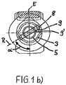
- the second clamping pin 8 is seated in clamping hole bores 9, 9 'of the middle profile tube 3 and the tie rod 5, as in the Figure 1 b can be seen.
- the Spannlochbohronne 9 have from the axial end 21 of the central profile tube 3 about a distance of 10 mm and the Spannlochbohronne 9 'have from the axial end 20 of the tie rod 5 about a distance of 10 mm.
- the second clamping pin 8 is seated at an angle ⁇ of 60 ° in the middle profile tube 3 and the pull rod 5 in the clamping hole bores 9, 9 'relative to an axial plane E.
- Other angles ⁇ may also be provided.
- the pull rod 5 has a round cross-section.
- the pull rod 5 has two diametrically opposite axial slots 6, 6 ', of which in the FIG. 1a only the slot 6 can be seen. From the axial end 20 of the pull rod 5, the axial slots 6, 6 'have a distance of about 25 mm. Through the two axial slots 6, 6 'engage engagement means in the form of a first clamping pin 7 radially therethrough. The first clamping pin 7 is held in clamping pin holes 16 of the inner profile tube 2.
- the Spannjanbohrept 16 have from the axial end 18 of the inner profile tube 2 about a distance of 15 mm.
- the inner profile tube 2 is first pulled out relative to the middle profile tube 3 and connected to the middle profile tube 3 pull rod 5. In this case, passes through the first dowel pin 7, which is connected to the inner profile tube 2, the axial slots 6, 6 'of the tie rod 5. At the moment in which the first dowel pin 7 has passed through the axial slots completely, i. strikes, in the extension direction on the first clamping pin 7 and the tie rod 5 is a positive connection between the inner profile tube 2 and the middle profile tube 3, so that a further extension movement of the telescopic shaft 1 takes place via an extending the middle profile tube 3 relative to the outer profile tube 4.
- the displacement between the inner profile tube 2 and the tie rod 5 is limited.
- the insertion of the telescopic shaft 1 takes place in the reverse order or alternatively, by first the inner profile tube 2 with respect to the pull rod 5 einschiebt, wherein the first clamping pin 7, the axial slots 6, 6 'passes, and then the middle profile tube 3 is taken from the pull rod 5 and pushes against the outer profile tube 4.
- a bore is provided on the circumference of the sleeve 30 of the protective tube 14.
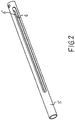
- FIG. 2 shows an example of a tension element 5 with the two axial slots 6, 6 '.
- the tension element according to FIG. 3 be constructed, this is not made of a tube, are introduced into the slots.
- the tension element according to FIG. 3 it is a built-in tension element with two rectangular cross-section tie rods 32, 33 which are parallel to each other. At one of their ends, the tie rods 32, 33 are welded to a tubular end member 34.
- the end element 34 at one of its ends on the front side two slots 35 into which the ends of the tie rods 32, 33 are inserted.
- the slots 35 extend over a portion of the length of the end member 34 and penetrate the entire wall thickness thereof.
- Such a closure element may also be provided at the other ends of the tie rods 32, 33.
- two cup-shaped end portions 36, 37 are provided which are connected to the tie rods 32, 33 so as to collectively form a tubular end member. This type of connection can also be provided instead of the end element 34 at the other end.
Landscapes
- Engineering & Computer Science (AREA)
- General Engineering & Computer Science (AREA)
- Mechanical Engineering (AREA)
- Ocean & Marine Engineering (AREA)
- Mutual Connection Of Rods And Tubes (AREA)
- Shafts, Cranks, Connecting Bars, And Related Bearings (AREA)
- Steering Controls (AREA)
Description
- Die Erfindung betrifft eine Teleskopwelle zur Übertragung von Drehmomenten, umfassend ein inneres Profilrohr, ein mittleres Profilrohr und ein äußeres Profilrohr, die zur Längenänderung verschiebbar zueinander angeordnet sind, wobei ein Zugelement in dem mittleren Profilrohr axial unverschieblich gehalten ist.
- Mehrteilige Teleskopwellen sind im Stand der Technik bekannt. Bei diesen stellt sich das Problem, wie bei einem Auszug des inneren Profilrohrs gegenüber dem mittleren Profilrohr das mittlere Profilrohr, nachdem das innere Profilrohr eine gewisse Strecke gegenüber diesem ausgezogen wurde, mitbewegt werden kann, um gegenüber dem äußeren Profilrohr auszuziehen. Hierfür kann ein Zugdraht Verwendung finden, der mit seinem einen Ende an einem axialen Ende des inneren Profilrohr befestigt ist, durch dieses hindurchgeführt ist und mit seinem anderen Ende an einem axialen Ende des mittleren Profilrohrs befestigt ist. Im zusammengefahrenen Zustand der Teleskopwelle liegt der Zugdraht lose in dem inneren Profilrohr, d.h. seine Länge ist größer als der axiale Abstand der Befestigungen an den jeweiligen Profilrohren. Somit kann das innere Profilrohr um ein gewisses Maß gegenüber dem mittleren Profilrohr herausgezogen werden, bevor der Zugdraht straff gezogen ist und das mittlere Profilrohr mitzieht. Das Problem dieser Kopplung ist die mangelnde Robustheit des Zugdrahtes, der den auftretenden Belastungen nach einer gewissen Gebrauchsdauer nicht mehr Stand hält.
- Aus der
DE 33 34 709 C2 ist eine Teleskopwelle mit einem äußeren und einem inneren Profilrohr bekannt. Innerhalb der beiden Profilrohre sind ein innerer Zuganker und ein äußerer Zuganker angeordnet, die jeweils über Rastkörper zu einem der Profilrohre lösbar verbunden sind. Der innere Zuganker weist diametral gegenüberliegende Längsschlitze auf, in denen ein Fangbolzen geführt ist, der mit dem äußeren Zuganker verbunden ist. Der Fangbolzen durchwandert die Längschlitze, wenn die Teleskopwelle auseinandergezogen wird. Ein weiteres Auseinanderziehen ist möglich, indem die Rastkörper zwischen den Zugankern und dem jeweiligen Profilrohr in eine ausgezogene Raststellung wandern. Im auseinandergezogenen Zustand kann die Teleskopwelle kein Drehmoment übertragen. - Gemäß dem Oberbegriff des Anspruchs 1 offenbart die
US 73 914 eine dreiteilige Teleskopwelle mit Mitteln, die sicherstellen, dass ein mittleres Profilrohr herausgezogen werden kann. - Aufgabe der vorliegenden Erfindung ist es, eine Teleskopwelle bereitzustellen, die im ausgezogenen Zustand Drehmoment übertragen kann und deren Kopplung der Profilrohre robust im Hinblick auf die auftretenden Belastungen ist.
- Die Aufgabe wird gelöst durch eine Teleskopwelle zur Übertragung von Drehmomenten, umfassend ein inneres Profilrohr, ein mittleres Profilrohr und ein äußeres Profilrohr, die zur Längenänderung verschiebbar zueinander angeordnet sind, wobei ein Zugelement mit zumindest einem axialen Langloch in dem mittleren Profilrohr axial unverschiebbar gehalten ist und wobei Eingriffsmittel mit dem inneren Profilrohr verbunden sind und die Eingriffsmittel in das zumindest eine axiale Langloch des Zugelements zur Begrenzung eines Verschiebeweges zwischen dem inneren Profilrohr und dem Zugelement eingreifen.
- Der Vorteil dieser erfindungsgemäßen Ausgestaltung besteht darin, dass durch die Befestigung des Zugelements zu seiner einen Seite an dem mittleren Profilrohr und durch den Eingriff der Eingriffsmittel des inneren Profilrohrs in das Langloch des Zugelements eine robuste und belastbare Verbindung zwischen dem inneren und dem mittleren Profilrohr erzielt wird. Weiterhin ist von Vorteil, dass die Herstellung eines Langlochs fertigungstechnisch einfach zu realisieren ist, wobei dennoch das Zugelement bezüglich der kritischen Zugbelastungen nicht in einem erheblichen Maße geschwächt ist. Weiterhin kann für die Anfertigung des Zugelements auf allseits verfügbare Norm- oder Meterware zurückgegriffen werden.
- Bevorzugt umfasst das Zugelement ein Rohr mit einem runden Querschnitt. Ein geringes Gewicht des Zugelements gegenüber einem vollen Querschnitt ist somit gewährleistet. Ein runder Querschnitt ist vorteilhaft, da somit keine passgenaue Anpassung an die Profilierung der Profilrohre erfolgen muss.
- In konkreter Ausgestaltung des rohrförmigen Zugelements sind zwei beidseitig gegenüberliegende axiale Langlöcher vorgesehen. Vorteilhaft ist hier die Rotationssymmetrie des Zugelements. Bevorzugt greifen die Eingriffsmittel diametral durch die axialen Langlöcher. Hierdurch ist in vorteilhafter Weise gewährleistet, dass die Eingriffsmittel zu beiden axialen Seiten dieses Durchgriffs durch das Zugelement mit dem inneren Profilrohr verbunden bzw. an diesem befestigt werden können.
- Das Zugelement kann ein Rohr umfasst bzw. aus einem Rohr gefertigt sein, in dessen Wandung das mindestens eine Langloch eingebracht ist. Alternativ kann das Zugelement zwei axial ausgerichtete parallel zueinander angeordnete Zugstangen umfasst, z.B. aus Flachstahl, die an ihren axialen Enden über Abschlusselemente einen Rohrabschnitt bildend miteinander verbunden sind. Hierbei können die Abschlusselemente selbst rohrförmig gestaltet sein, die mit den Enden der Zugstangen verbunden sind, und/oder schalenförmig gestaltet sein, um zusammen mit den Zugstangen einen rohrförmigen Abschnitt zu bilden.
- Bevorzugt umfassen die Eingriffsmittel einen ersten Spannstift. In weiterhin bevorzugter Ausgestaltung ist das Zugelement über einen zweiten Spannstift gegenüber dem mittleren Profilrohr gehalten. In vorteilhafter Weise kann somit bezüglich der Eingriffsmittel auf allseits verfügbare Normteile zurückgegriffen werden.
- In Konkretisierung ist vorgesehen, dass der zweite Spannstift in Spannstiftbohrungen jeweils des mittleren Profilrohrs und des Zugelements, welches bevorzugt rohrförmig ausgebildet ist, einsitzt. Eine derartige Verbindung ist fertigungstechnisch einfach darzustellen.
- Bevorzugt sitzt das innere Profilrohr zwischen dem Zugelement und dem mittleren Profilrohr verschiebbar ein. Als Vorteil ist bezüglich dieser Anordnung zu nennen, dass sich das Zugelement ohne größeren Aufwand in bestehende mehrteilige Teleskopwellen nachrüsten lässt.
- In weiterer Ausgestaltung der Erfindung verläuft eine erste Radialachse der Spannstiftbohrung in dem Zugelement abweichend von einem rechten Winkel zu einer axialen Ebene, die durch das zumindest eine axiale Langloch und eine Längsachse der Teleskopwelle aufgespannt wird. Bevorzugt verläuft eine zweite Radialachse der Spannstiftbohrung in dem mittleren Profilrohr abweichend von einem rechten Winkel zu einer axialen Ebene, die durch das zumindest eine axiale Langloch und eine Längsachse der Teleskopwelle aufgespannt wird. Insbesondere ist bevorzugt, dass die erste und die zweite Radialachse der Spannstiftbohrungen aufeinanderliegen.
- Die Aufgabe wird ferner gelöst durch eine Gelenkwelle mit einer erfindungsgemäßen Teleskopwelle, wobei ein erstes Gelenk mit dem inneren Profilrohr drehfest verbunden ist und ein zweites Gelenk mit dem äußeren Profilrohr drehfest verbunden ist. Bevorzugt handelt es sich bei den Gelenken jeweils um Kreuzgelenke.
- Im folgenden wird die erfindungsgemäße Teleskopwelle anhand der Figuren beschrieben. Hierin zeigt
- Figur 1a
- einen Längsschnitt durch die erfindungsgemäße Teleskopwelle,
- Figur 1b
- einen Querschnitt entlang der Schnittlinie I-I in
Figur 1a , - Figur 2
- das Zugelement der Teleskopwelle gemäß
Figur 1 a und - Figur 3
- ein alternatives Zugelement.
- In der
Figur 1 ist eine Gelenkwelle 31 mit Kreuzgelenken 11, 12 und einer dreiteilig auseinanderziehbaren Teleskopwelle 1 in vollständig eingeschobenem Zustand dargestellt. Die Teleskopwelle 1 besteht aus einem inneren Profilrohr 2, welches an seinem einen axialen Ende 17 mit dem ersten Kreuzgelenks 11 drehfest verbunden ist, einem äußeren Profilrohr 4, welches an seinem einen axialen Ende 19 mit dem zweiten Kreuzgelenk 12 drehfest verbunden ist, und einem mittleren Profilrohr 3. Die Profilrohre 2, 3, 4 sind teleskopisch ineinandergeschoben, wobei das mittlere Profilrohr 3 zwischen dem inneren Profilrohr 2 und dem äußeren Profilrohr 4 angeordnet ist. - Zum Schutz beispielsweise der Bedienperson vor der drehenden Gelenkwelle 31 ist diese mit einem äußeren Schutzrohr 13 und einem inneren Schutzrohr 14 versehen, die beide zum Längenausgleich teleskopisch ineinander gesteckt sind. Jedes Schutzrohr 13, 14 ist im Bereich des jeweiligen Kreuzgelenks 11, 12 an dem äußeren bzw. inneren Profilrohr 4, 2 befestigt. Die Schutzrohre 13, 14 sind mit Ketten 15 gegen Verdrehen gesichert.
- Innerhalb des inneren Profilrohrs 2 ist ein Zugelement in Form einer Zugstange 5 angeordnet, welche ein Rohr 10 umfasst. Die Zugstange 5 steht axial über das axiale Ende 18 des inneren Profilrohrs 2 über, welches der an dem inneren Profilrohr 2 befestigten Kreuzgelenk 11 abgewandt ist. In diesem überstehende Bereich ist die Zugstange 5 mittels eines zweiten Spannstifts 8 an dem mittleren Profilrohr 3 gehalten. Hierzu sitzt der zweite Spannstift 8 in Spannlochbohrungen 9, 9' des mittleren Profilrohrs 3 und der Zugstange 5 ein, wie in der
Figur 1 b zu erkennen ist. Die Spannlochbohrungen 9 haben von dem axialen Ende 21 des mittleren Profilrohrs 3 etwa einen Abstand von 10 mm und die Spannlochbohrungen 9' haben von dem axialen Ende 20 der Zugstange 5 etwa einen Abstand von 10 mm. - In der
Figur 1 b ist zu erkennen, dass der zweite Spannstift 8 bezogen auf eine axiale Ebene E unter einem Winkel α von 60° in dem mittleren Profilrohr 3 und der Zugstange 5 in den Spannlochbohrungen 9, 9' einsitzt. Andere Winkel α können ebenso vorgesehen werden. Zu erkennen ist ferner die Profilierung des mittleres Profilrohrs 3, die entsprechend bei dem inneren Profilrohr 2 und dem äußeren Profilrohr ausgebildet ist und über deren formschlüssigen Eingriff ein Drehmoment übertragen werden kann. Die Zugstange 5 weist einen runden Querschnitt auf. - Die Zugstange 5 weist zwei diametral gegenüberliegende axiale Langlöcher 6, 6' auf, von denen in der
Figur 1a nur das Langloch 6 zu erkennen ist. Von dem axialen Ende 20 der Zugstange 5 haben die axialen Langlöcher 6, 6' etwa einen Abstand von 25 mm. Durch die beiden axialen Langlöcher 6, 6' greifen Eingriffsmittel in Form eines ersten Spannstifts 7 radial hindurch. Der erste Spannstift 7 ist in Spannstiftbohrungen 16 des inneren Profilrohrs 2 gehalten. Die Spannstiftbohrungen 16 haben von dem axialen Ende 18 des inneren Profilrohrs 2 etwa einen Abstand von 15 mm. Bei der Darstellung in derFigur 1 b ist zu beachten, dass die Zugstange 5 mit den axialen Langlöchern 6, 6' und der erste Spannstift 7 gegenüber der restlichen Darstellung um 90° gedreht dargestellt sind, d.h. realiter verläuft die Radialachse des ersten Spannstifts 7 in der Zeichnungsebene, d.h. verglichen mit dem zweiten Spannstift 8 demnach nicht winklig zu der axialen Ebene E, welche inFigur 1 b eingezeichnet ist. - Bei einer Ausziehbewegung des Teleskopwelle 1 wird das innere Profilrohr 2 zunächst gegenüber dem mittleren Profilrohr 3 und der mit dem mittleren Profilrohr 3 verbundenen Zugstange 5 herausgezogen. Hierbei durchläuft der erste Spannstift 7, der mit dem inneren Profilrohr 2 verbunden ist, die axialen Langlöcher 6, 6' der Zugstange 5. In dem Augenblick, in dem der erste Spannstift 7 die axialen Langlöcher vollständig durchlaufen hat, d.h. anschlägt, besteht in Auszugsrichtung über den ersten Spannstift 7 und die Zugstange 5 eine formschlüssige Verbindung zwischen dem inneren Profilrohr 2 und dem mittleren Profilrohr 3, so dass eine weitere Ausziehbewegung der Teleskopwelle 1 über ein Ausziehen des mittleren Profilrohrs 3 gegenüber dem äußeren Profilrohr 4 stattfindet. Durch den Eingriff des ersten Spannstifts 7, der mit dem inneren Profilrohr 2 verbunden ist, in die axialen Langlöcher 6, 6' der Zugstange 5 wird der Verschiebeweg zwischen dem inneren Profilrohr 2 und der Zugstange 5 begrenzt. Das Einschieben der Teleskopwelle 1 erfolgt in umgekehrter Reihenfolge oder alternativ, indem zuerst das innere Profilrohr 2 gegenüber der Zugstange 5 einschiebt, wobei der erste Spannstift 7 die axialen Langlöcher 6, 6' durchläuft, und anschließend das mittlere Profilrohr 3 von der Zugstange 5 mitgenommen wird und gegenüber dem äußeren Profilrohr 4 einschiebt.
- Die Schmierung des Schutzlaufrings 27 des äußeren Schutzrohrs 13 auf dem Lagerring 26 des mittleren Profilrohrs 3 erfolgt über Schmiernippel 22, 23, Bohrungen 24, 25 und Bohrungen 28, 29 in der Axialebene des Lagerrings 24 in dem mittleren Profilrohr 3.
- Zur Montage des zweiten Spannstifts 8 ist eine nicht dargestellte Bohrung auf dem Umfang der Manschette 30 des Schutzrohrs 14 vorgesehen.
- Bei dieser erfindungsgemäßen Lösung einer Zugstange 5, die eine formschlüssige Verbindung zwischen dem inneren Profilrohr 2 und dem mittleren Profilrohr 3 bildet, wird eine robuste Ausziehmechanik für eine Gelenkwelle 31 mit einer mehrteiligen Teleskopwelle 1 bereitgestellt.
-
Figur 2 zeigt beispielhaft ein Zugelement 5 mit den beiden axialen Langlöchern 6, 6'. Alternativ kann das Zugelement gemäßFigur 3 aufgebaut sein, wobei dieses nicht aus einem Rohr hergestellt ist, in das Langlöcher eingebracht sind. Bei der Ausführungsform gemäßFigur 3 handelt es sich um ein gebautes Zugelement mit zwei im Querschnitt rechteckigen Zugstangen 32, 33, die parallel zueinander verlaufen. An einem ihrer Enden sind die Zugstangen 32, 33 mit einem rohrförmigen Abschlusselement 34 verschweißt. Hierfür weist das Abschlusselement 34 an einem seiner Enden stirnseitig zwei Schlitze 35 auf, in die die Enden der Zugstangen 32, 33 eingesetzt sind. Die Schlitze 35 verlaufen über einen Teil der Länge des Abschlusselements 34 und durchdringen die gesamte Wandstärke desselben. Grundsätzlich reichen jedoch auch Nuten in der Außenumfangsfläche des Abschlusselements 34, sofern das Abschlusselement 34 eine dickere Wandstärke aufweist als die Zugstangen 32, 33. Im vorliegenden Fall ist die Wanddicke des Abschlusselements 34 identisch zu der der Zugstangen 32, 33. - Ein solches Abschlusselement kann auch an den anderen Enden der Zugstangen 32, 33 vorgesehen sein. Alternativ, wie hier dargestellt, sind zwei schalenförmige Abschlussteile 36, 37 vorgesehen, die derart mit den Zugstangen 32, 33 verbunden sind, dass sie gemeinsam ein rohrförmiges Abschlusselement bilden. Diese Art der Anbindung kann auch anstelle des Abschlusselements 34 am anderen Ende vorgesehen sein.
-
- 1
- Teleskopwelle
- 2
- inneres Profilrohr
- 3
- mittleres Profilrohr
- 4
- äußeres Profilrohr
- 5
- Zugelement
- 6; 6'
- axiales Langloch
- 7
- Eingriffsmittel, erster Spannstift
- 8
- zweiter Spannstift
- 9, 9'
- Spannstiftbohrung
- 10
- Rohr
- 11
- Kreuzgelenk
- 12
- Kreuzgelenk
- 13
- Schutzrohr
- 14
- Schutzrohr
- 15
- Kette
- 16
- Spannstiftbohrung
- 17
- axiales Ende
- 18
- axiales Ende
- 19
- axiales Ende
- 20
- axiales Ende
- 21
- axiales Ende
- 22
- Schmiernippel
- 23
- Schmiernippel
- 24
- Bohrung
- 25
- Bohrung
- 26
- Lagerring
- 27
- Schutzlaufring
- 28
- Bohrung
- 29
- Bohrung
- 30
- Manschette
- 31
- Gelenkwelle
- 32
- Zugstange
- 33
- Zugstange
- 34
- Abschlusselement
- 35
- Schlitz
- 36
- Abschlussteil
- 37
- Abschlussteil
- E
- axiale Ebene
- R
- Radialachse
Claims (12)
- Teleskopwelle (1) zur Übertragung von Drehmomenten, umfassend ein inneres Profilrohr (2), ein mittleres Profilrohr (3) und ein äußeres Profilrohr (4), die zur Längenänderung verschiebbar zueinander angeordnet sind, wobei Eingriffsmittel (7) mit dem inneren Profilrohr (2) verbunden sind,
dadurch gekennzeichnet,
dass ein Zugelement (5) mit zumindest einem axialen Langloch (6) in dem mittleren Profilrohr (3) axial unverschiebbar gehalten ist und
die Eingriffsmittel (7) in das zumindest eine axiale Langloch (6) des Zugelements (5) zur Begrenzung eines Verschiebeweges zwischen dem inneren Profilrohr (2) und dem Zugelement (5) eingreifen. - Teleskopwelle (1) nach Anspruch 1,
dadurch gekennzeichnet,
dass zwei beidseitig gegenüberliegende axiale Langlöcher (6, 6') vorgesehen sind. - Teleskopwelle (1) nach Anspruch 2,
dadurch gekennzeichnet,
dass die Eingriffsmittel (7) durch die axialen Langlöcher (6, 6') diametral durchgreifen. - Teleskopwelle (1) nach einem der Ansprüche 1 bis 3,
dadurch gekennzeichnet,
dass das Zugelement (5) ein Rohr (10) umfasst, in dessen Wandung das mindestens eine Langloch eingebracht ist. - Teleskopwelle (1) nach einem der Ansprüche 1 bis 3,
dadurch gekennzeichnet,
dass das Zugelement (5) zwei axial ausgerichtete parallel zueinander angeordnete Zugstangen (32, 33) umfasst, die an ihren axialen Enden über Abschlusselemente (34) einen Rohrabschnitt bildend miteinander verbunden sind. - Teleskopwelle (1) nach einem der Ansprüche 1 bis 5,
dadurch gekennzeichnet,
dass die Eingriffsmittel einen ersten Spannstift (7) umfassen. - Teleskopwelle (1) nach einem der Ansprüche 1 bis 6,
dadurch gekennzeichnet,
dass das Zugelement (5) über einen zweiten Spannstift (8) gegenüber dem mittleren Profilrohr (3) gehalten ist. - Teleskopwelle (1) nach Anspruch 7,
dadurch gekennzeichnet,
dass der zweite Spannstift (8) in Spannstiftbohrungen (9, 9') jeweils des mittleren Profilrohrs (3) und des Zugelements (5) einsitzt. - Teleskopwelle (1) nach einem der Ansprüche 1 bis 8,
dadurch gekennzeichnet,
dass das innere Profilrohr (2) zwischen dem Zugelement (5) und dem mittleren Profilrohr (3) verschiebbar einsitzt. - Teleskopwelle (1) nach Anspruch 8 oder Anspruch 9, wenn abhängig von Anspruch 8,
dadurch gekennzeichnet,
dass eine erste Radialachse (R) der Spannstiftbohrung (9') in dem Zugelement (5) abweichend von einen rechten Winkel zu einer axialen Ebene verläuft, die durch das zumindest eine axiale Langloch (6) und eine Längsachse (A) der Teleskopwelle (1) aufgespannt wird. - Teleskopwelle (1) nach Anspruch 8 oder einem der Ansprüche 9 und 10, wenn abhängig von Anspruch 8,
dadurch gekennzeichnet,
dass eine zweite Radialachse (R) der Spannstiftbohrung (9) in dem mittleren Profilrohr (3) abweichend von einen rechten Winkel zu einer axialen Ebene (E) verläuft, die durch das zumindest eine axiale Langloch (6) und eine Längsachse (A) der Teleskopwelle (1) aufgespannt wird. - Gelenkwelle (31) mit einer Teleskopwelle (1) nach einem der vorangegangenen Ansprüche, wobei ein erstes Gelenk (11) mit dem inneren Profilrohr (2) drehfest verbunden ist und ein zweites Gelenk (12) mit dem äußeren Profilrohr (4) drehfest verbunden ist.
Applications Claiming Priority (1)
| Application Number | Priority Date | Filing Date | Title |
|---|---|---|---|
| DE102011055169A DE102011055169B3 (de) | 2011-11-09 | 2011-11-09 | Teleskopwelle mit Zugelement |
Publications (2)
| Publication Number | Publication Date |
|---|---|
| EP2592287A1 EP2592287A1 (de) | 2013-05-15 |
| EP2592287B1 true EP2592287B1 (de) | 2017-03-29 |
Family
ID=46801340
Family Applications (1)
| Application Number | Title | Priority Date | Filing Date |
|---|---|---|---|
| EP12182453.6A Active EP2592287B1 (de) | 2011-11-09 | 2012-08-30 | Teleskopwelle mit Zugelement |
Country Status (3)
| Country | Link |
|---|---|
| US (1) | US8870667B2 (de) |
| EP (1) | EP2592287B1 (de) |
| DE (1) | DE102011055169B3 (de) |
Families Citing this family (4)
| Publication number | Priority date | Publication date | Assignee | Title |
|---|---|---|---|---|
| US20180065465A1 (en) | 2015-08-23 | 2018-03-08 | Arctic Cat Inc. | Off-Road Recreational Vehicle |
| US20170136874A1 (en) | 2015-08-23 | 2017-05-18 | Brian Harris | Off road vehicle |
| US11028883B2 (en) | 2017-11-13 | 2021-06-08 | Arctic Cat Inc. | Off-road recreational vehicle |
| US11712925B2 (en) | 2019-07-01 | 2023-08-01 | Textron Inc. | Axial plunging half-shaft assembly |
Citations (1)
| Publication number | Priority date | Publication date | Assignee | Title |
|---|---|---|---|---|
| US73914A (en) * | 1868-01-28 | Improvement in harvesters |
Family Cites Families (9)
| Publication number | Priority date | Publication date | Assignee | Title |
|---|---|---|---|---|
| US1791001A (en) * | 1931-02-03 | Steering-wheel post | ||
| US768186A (en) * | 1903-03-25 | 1904-08-23 | Robert A Lachmann | Drill-sleeve. |
| US1278459A (en) * | 1918-04-06 | 1918-09-10 | Guy V Hale | Shaft-coupling. |
| US2385608A (en) * | 1942-06-03 | 1945-09-25 | Castagna James | Curtain and drapery rod |
| DE2952029A1 (de) * | 1979-12-22 | 1981-07-02 | Zahnradfabrik Friedrichshafen Ag, 7990 Friedrichshafen | Teleskopspindel |
| DE3334709C2 (de) | 1983-09-24 | 1985-07-25 | Jean Walterscheid Gmbh, 5204 Lohmar | Teleskopwelle |
| FR2750750B1 (fr) * | 1996-07-04 | 1998-11-06 | Guerineau Philippe | Dispositif de securite pour desolidariser un arbre mene telescopique, notamment d'une prise de force |
| US7207890B2 (en) * | 2004-11-03 | 2007-04-24 | Cnh America Llc | Tubular telescoping drive shaft |
| JP2007247846A (ja) * | 2006-03-17 | 2007-09-27 | Jtekt Corp | 伸縮自在シャフト |
-
2011
- 2011-11-09 DE DE102011055169A patent/DE102011055169B3/de not_active Expired - Fee Related
-
2012
- 2012-08-30 EP EP12182453.6A patent/EP2592287B1/de active Active
- 2012-11-07 US US13/670,724 patent/US8870667B2/en active Active
Patent Citations (1)
| Publication number | Priority date | Publication date | Assignee | Title |
|---|---|---|---|---|
| US73914A (en) * | 1868-01-28 | Improvement in harvesters |
Also Published As
| Publication number | Publication date |
|---|---|
| EP2592287A1 (de) | 2013-05-15 |
| US20130116057A1 (en) | 2013-05-09 |
| DE102011055169B3 (de) | 2013-03-21 |
| US8870667B2 (en) | 2014-10-28 |
Similar Documents
| Publication | Publication Date | Title |
|---|---|---|
| DE3334709C2 (de) | Teleskopwelle | |
| DE19911111C1 (de) | Anordnung mit einem Gleichlauffestgelenk und einer Verbindungswelle | |
| EP2744626B1 (de) | Pressvorrichtung | |
| EP2895769B1 (de) | Kettenverbindungselement mit sicherungssteg | |
| EP2592287B1 (de) | Teleskopwelle mit Zugelement | |
| EP3634170A1 (de) | Klemmvorrichtung für einen längenverstellbaren stock | |
| DE1784533A1 (de) | Vorzufertigendes Bauelement | |
| DE102007036554B4 (de) | Deckel-Lager-Anordnung und Verfahren zum Montieren einer Aktuatorwelle | |
| DE102005034063B3 (de) | Vorrichtung zum Verschließen von Gebäudeöffnungen | |
| DE3221007A1 (de) | Schutzvorrichtung fuer kardanwellen | |
| DE102008013227B4 (de) | Verfahren zum Herstellen einer Verbindung eines Getriebebauteils | |
| EP1956252B1 (de) | Längsverschiebeeinheit für Gelenkwellen | |
| DE4441019C2 (de) | Wellenkupplung | |
| DE10007773A1 (de) | Kran mit einem Teleskopausleger | |
| EP2706276B1 (de) | Innenwandig verstärktes rohr und verfahren zu dessen herstellung | |
| DE102016007495B4 (de) | Gleichlaufgelenk mit integralem Gelenkinnenteil und Verfahren zur Herstellung eines solchen Gleichlaufgelenks | |
| DE102013110983A1 (de) | Verbindungssystem | |
| DE2619830B2 (de) | Abschleppstange für Kraftfahrzeuge | |
| EP2605943B1 (de) | Stützvorrichtung für einen sattelanhänger, umfassend einen spindelmechanismus mit mehrteiliger spindel, sowie sattelanhänger mit einer solchen stützvorrichtung | |
| DE202011106767U1 (de) | Ecklager | |
| AT525434B1 (de) | Teleskop- und/oder Faltstock | |
| EP1055830B1 (de) | Gelenkwelle | |
| EP1055635A2 (de) | Kran mit Einem Teleskopausleger | |
| DE102013016982B4 (de) | Klappmechanismus | |
| DE974103C (de) | Vieleck- oder bogenfoermiger, eiserner Grubenausbau |
Legal Events
| Date | Code | Title | Description |
|---|---|---|---|
| PUAI | Public reference made under article 153(3) epc to a published international application that has entered the european phase |
Free format text: ORIGINAL CODE: 0009012 |
|
| AK | Designated contracting states |
Kind code of ref document: A1 Designated state(s): AL AT BE BG CH CY CZ DE DK EE ES FI FR GB GR HR HU IE IS IT LI LT LU LV MC MK MT NL NO PL PT RO RS SE SI SK SM TR |
|
| AX | Request for extension of the european patent |
Extension state: BA ME |
|
| 17P | Request for examination filed |
Effective date: 20131016 |
|
| RBV | Designated contracting states (corrected) |
Designated state(s): AL AT BE BG CH CY CZ DE DK EE ES FI FR GB GR HR HU IE IS IT LI LT LU LV MC MK MT NL NO PL PT RO RS SE SI SK SM TR |
|
| 17Q | First examination report despatched |
Effective date: 20140317 |
|
| GRAJ | Information related to disapproval of communication of intention to grant by the applicant or resumption of examination proceedings by the epo deleted |
Free format text: ORIGINAL CODE: EPIDOSDIGR1 |
|
| GRAP | Despatch of communication of intention to grant a patent |
Free format text: ORIGINAL CODE: EPIDOSNIGR1 |
|
| GRAP | Despatch of communication of intention to grant a patent |
Free format text: ORIGINAL CODE: EPIDOSNIGR1 |
|
| INTG | Intention to grant announced |
Effective date: 20161011 |
|
| GRAJ | Information related to disapproval of communication of intention to grant by the applicant or resumption of examination proceedings by the epo deleted |
Free format text: ORIGINAL CODE: EPIDOSDIGR1 |
|
| GRAR | Information related to intention to grant a patent recorded |
Free format text: ORIGINAL CODE: EPIDOSNIGR71 |
|
| GRAS | Grant fee paid |
Free format text: ORIGINAL CODE: EPIDOSNIGR3 |
|
| GRAA | (expected) grant |
Free format text: ORIGINAL CODE: 0009210 |
|
| INTC | Intention to grant announced (deleted) | ||
| AK | Designated contracting states |
Kind code of ref document: B1 Designated state(s): AL AT BE BG CH CY CZ DE DK EE ES FI FR GB GR HR HU IE IS IT LI LT LU LV MC MK MT NL NO PL PT RO RS SE SI SK SM TR |
|
| INTG | Intention to grant announced |
Effective date: 20170217 |
|
| REG | Reference to a national code |
Ref country code: GB Ref legal event code: FG4D Free format text: NOT ENGLISH |
|
| REG | Reference to a national code |
Ref country code: CH Ref legal event code: EP |
|
| REG | Reference to a national code |
Ref country code: AT Ref legal event code: REF Ref document number: 880069 Country of ref document: AT Kind code of ref document: T Effective date: 20170415 |
|
| REG | Reference to a national code |
Ref country code: IE Ref legal event code: FG4D Free format text: LANGUAGE OF EP DOCUMENT: GERMAN |
|
| REG | Reference to a national code |
Ref country code: DE Ref legal event code: R096 Ref document number: 502012009891 Country of ref document: DE |
|
| REG | Reference to a national code |
Ref country code: NL Ref legal event code: FP |
|
| PG25 | Lapsed in a contracting state [announced via postgrant information from national office to epo] |
Ref country code: LT Free format text: LAPSE BECAUSE OF FAILURE TO SUBMIT A TRANSLATION OF THE DESCRIPTION OR TO PAY THE FEE WITHIN THE PRESCRIBED TIME-LIMIT Effective date: 20170329 Ref country code: FI Free format text: LAPSE BECAUSE OF FAILURE TO SUBMIT A TRANSLATION OF THE DESCRIPTION OR TO PAY THE FEE WITHIN THE PRESCRIBED TIME-LIMIT Effective date: 20170329 Ref country code: GR Free format text: LAPSE BECAUSE OF FAILURE TO SUBMIT A TRANSLATION OF THE DESCRIPTION OR TO PAY THE FEE WITHIN THE PRESCRIBED TIME-LIMIT Effective date: 20170630 Ref country code: HR Free format text: LAPSE BECAUSE OF FAILURE TO SUBMIT A TRANSLATION OF THE DESCRIPTION OR TO PAY THE FEE WITHIN THE PRESCRIBED TIME-LIMIT Effective date: 20170329 Ref country code: NO Free format text: LAPSE BECAUSE OF FAILURE TO SUBMIT A TRANSLATION OF THE DESCRIPTION OR TO PAY THE FEE WITHIN THE PRESCRIBED TIME-LIMIT Effective date: 20170629 |
|
| REG | Reference to a national code |
Ref country code: FR Ref legal event code: PLFP Year of fee payment: 6 |
|
| PG25 | Lapsed in a contracting state [announced via postgrant information from national office to epo] |
Ref country code: SE Free format text: LAPSE BECAUSE OF FAILURE TO SUBMIT A TRANSLATION OF THE DESCRIPTION OR TO PAY THE FEE WITHIN THE PRESCRIBED TIME-LIMIT Effective date: 20170329 Ref country code: LV Free format text: LAPSE BECAUSE OF FAILURE TO SUBMIT A TRANSLATION OF THE DESCRIPTION OR TO PAY THE FEE WITHIN THE PRESCRIBED TIME-LIMIT Effective date: 20170329 Ref country code: BG Free format text: LAPSE BECAUSE OF FAILURE TO SUBMIT A TRANSLATION OF THE DESCRIPTION OR TO PAY THE FEE WITHIN THE PRESCRIBED TIME-LIMIT Effective date: 20170629 Ref country code: RS Free format text: LAPSE BECAUSE OF FAILURE TO SUBMIT A TRANSLATION OF THE DESCRIPTION OR TO PAY THE FEE WITHIN THE PRESCRIBED TIME-LIMIT Effective date: 20170329 |
|
| PG25 | Lapsed in a contracting state [announced via postgrant information from national office to epo] |
Ref country code: EE Free format text: LAPSE BECAUSE OF FAILURE TO SUBMIT A TRANSLATION OF THE DESCRIPTION OR TO PAY THE FEE WITHIN THE PRESCRIBED TIME-LIMIT Effective date: 20170329 Ref country code: CZ Free format text: LAPSE BECAUSE OF FAILURE TO SUBMIT A TRANSLATION OF THE DESCRIPTION OR TO PAY THE FEE WITHIN THE PRESCRIBED TIME-LIMIT Effective date: 20170329 Ref country code: RO Free format text: LAPSE BECAUSE OF FAILURE TO SUBMIT A TRANSLATION OF THE DESCRIPTION OR TO PAY THE FEE WITHIN THE PRESCRIBED TIME-LIMIT Effective date: 20170329 Ref country code: ES Free format text: LAPSE BECAUSE OF FAILURE TO SUBMIT A TRANSLATION OF THE DESCRIPTION OR TO PAY THE FEE WITHIN THE PRESCRIBED TIME-LIMIT Effective date: 20170329 Ref country code: SK Free format text: LAPSE BECAUSE OF FAILURE TO SUBMIT A TRANSLATION OF THE DESCRIPTION OR TO PAY THE FEE WITHIN THE PRESCRIBED TIME-LIMIT Effective date: 20170329 |
|
| PG25 | Lapsed in a contracting state [announced via postgrant information from national office to epo] |
Ref country code: PL Free format text: LAPSE BECAUSE OF FAILURE TO SUBMIT A TRANSLATION OF THE DESCRIPTION OR TO PAY THE FEE WITHIN THE PRESCRIBED TIME-LIMIT Effective date: 20170329 Ref country code: PT Free format text: LAPSE BECAUSE OF FAILURE TO SUBMIT A TRANSLATION OF THE DESCRIPTION OR TO PAY THE FEE WITHIN THE PRESCRIBED TIME-LIMIT Effective date: 20170731 Ref country code: IS Free format text: LAPSE BECAUSE OF FAILURE TO SUBMIT A TRANSLATION OF THE DESCRIPTION OR TO PAY THE FEE WITHIN THE PRESCRIBED TIME-LIMIT Effective date: 20170729 Ref country code: SM Free format text: LAPSE BECAUSE OF FAILURE TO SUBMIT A TRANSLATION OF THE DESCRIPTION OR TO PAY THE FEE WITHIN THE PRESCRIBED TIME-LIMIT Effective date: 20170329 |
|
| REG | Reference to a national code |
Ref country code: DE Ref legal event code: R097 Ref document number: 502012009891 Country of ref document: DE |
|
| PG25 | Lapsed in a contracting state [announced via postgrant information from national office to epo] |
Ref country code: DK Free format text: LAPSE BECAUSE OF FAILURE TO SUBMIT A TRANSLATION OF THE DESCRIPTION OR TO PAY THE FEE WITHIN THE PRESCRIBED TIME-LIMIT Effective date: 20170329 |
|
| PLBE | No opposition filed within time limit |
Free format text: ORIGINAL CODE: 0009261 |
|
| STAA | Information on the status of an ep patent application or granted ep patent |
Free format text: STATUS: NO OPPOSITION FILED WITHIN TIME LIMIT |
|
| 26N | No opposition filed |
Effective date: 20180103 |
|
| REG | Reference to a national code |
Ref country code: CH Ref legal event code: PL |
|
| PG25 | Lapsed in a contracting state [announced via postgrant information from national office to epo] |
Ref country code: MC Free format text: LAPSE BECAUSE OF FAILURE TO SUBMIT A TRANSLATION OF THE DESCRIPTION OR TO PAY THE FEE WITHIN THE PRESCRIBED TIME-LIMIT Effective date: 20170329 |
|
| GBPC | Gb: european patent ceased through non-payment of renewal fee |
Effective date: 20170830 |
|
| PG25 | Lapsed in a contracting state [announced via postgrant information from national office to epo] |
Ref country code: CH Free format text: LAPSE BECAUSE OF NON-PAYMENT OF DUE FEES Effective date: 20170831 Ref country code: LI Free format text: LAPSE BECAUSE OF NON-PAYMENT OF DUE FEES Effective date: 20170831 |
|
| REG | Reference to a national code |
Ref country code: IE Ref legal event code: MM4A |
|
| PG25 | Lapsed in a contracting state [announced via postgrant information from national office to epo] |
Ref country code: SI Free format text: LAPSE BECAUSE OF FAILURE TO SUBMIT A TRANSLATION OF THE DESCRIPTION OR TO PAY THE FEE WITHIN THE PRESCRIBED TIME-LIMIT Effective date: 20170329 |
|
| REG | Reference to a national code |
Ref country code: BE Ref legal event code: MM Effective date: 20170831 |
|
| PG25 | Lapsed in a contracting state [announced via postgrant information from national office to epo] |
Ref country code: LU Free format text: LAPSE BECAUSE OF NON-PAYMENT OF DUE FEES Effective date: 20170830 |
|
| PG25 | Lapsed in a contracting state [announced via postgrant information from national office to epo] |
Ref country code: IE Free format text: LAPSE BECAUSE OF NON-PAYMENT OF DUE FEES Effective date: 20170830 Ref country code: GB Free format text: LAPSE BECAUSE OF NON-PAYMENT OF DUE FEES Effective date: 20170830 |
|
| REG | Reference to a national code |
Ref country code: FR Ref legal event code: PLFP Year of fee payment: 7 |
|
| PG25 | Lapsed in a contracting state [announced via postgrant information from national office to epo] |
Ref country code: BE Free format text: LAPSE BECAUSE OF NON-PAYMENT OF DUE FEES Effective date: 20170831 |
|
| PG25 | Lapsed in a contracting state [announced via postgrant information from national office to epo] |
Ref country code: MT Free format text: LAPSE BECAUSE OF FAILURE TO SUBMIT A TRANSLATION OF THE DESCRIPTION OR TO PAY THE FEE WITHIN THE PRESCRIBED TIME-LIMIT Effective date: 20170329 |
|
| REG | Reference to a national code |
Ref country code: AT Ref legal event code: MM01 Ref document number: 880069 Country of ref document: AT Kind code of ref document: T Effective date: 20170830 |
|
| PG25 | Lapsed in a contracting state [announced via postgrant information from national office to epo] |
Ref country code: AT Free format text: LAPSE BECAUSE OF NON-PAYMENT OF DUE FEES Effective date: 20170830 |
|
| PG25 | Lapsed in a contracting state [announced via postgrant information from national office to epo] |
Ref country code: HU Free format text: LAPSE BECAUSE OF FAILURE TO SUBMIT A TRANSLATION OF THE DESCRIPTION OR TO PAY THE FEE WITHIN THE PRESCRIBED TIME-LIMIT; INVALID AB INITIO Effective date: 20120830 |
|
| PG25 | Lapsed in a contracting state [announced via postgrant information from national office to epo] |
Ref country code: CY Free format text: LAPSE BECAUSE OF NON-PAYMENT OF DUE FEES Effective date: 20170329 |
|
| PG25 | Lapsed in a contracting state [announced via postgrant information from national office to epo] |
Ref country code: MK Free format text: LAPSE BECAUSE OF FAILURE TO SUBMIT A TRANSLATION OF THE DESCRIPTION OR TO PAY THE FEE WITHIN THE PRESCRIBED TIME-LIMIT Effective date: 20170329 |
|
| PG25 | Lapsed in a contracting state [announced via postgrant information from national office to epo] |
Ref country code: TR Free format text: LAPSE BECAUSE OF FAILURE TO SUBMIT A TRANSLATION OF THE DESCRIPTION OR TO PAY THE FEE WITHIN THE PRESCRIBED TIME-LIMIT Effective date: 20170329 |
|
| PG25 | Lapsed in a contracting state [announced via postgrant information from national office to epo] |
Ref country code: AL Free format text: LAPSE BECAUSE OF FAILURE TO SUBMIT A TRANSLATION OF THE DESCRIPTION OR TO PAY THE FEE WITHIN THE PRESCRIBED TIME-LIMIT Effective date: 20170329 |
|
| REG | Reference to a national code |
Ref country code: DE Ref legal event code: R082 Ref document number: 502012009891 Country of ref document: DE Representative=s name: NEUMANN MUELLER OBERWALLENEY & PARTNER PATENTA, DE Ref country code: DE Ref legal event code: R081 Ref document number: 502012009891 Country of ref document: DE Owner name: WALTERSCHEID GMBH, DE Free format text: FORMER OWNER: GKN WALTERSCHEID GMBH, 53797 LOHMAR, DE |
|
| P01 | Opt-out of the competence of the unified patent court (upc) registered |
Effective date: 20230717 |
|
| PGFP | Annual fee paid to national office [announced via postgrant information from national office to epo] |
Ref country code: NL Payment date: 20250821 Year of fee payment: 14 |
|
| PGFP | Annual fee paid to national office [announced via postgrant information from national office to epo] |
Ref country code: DE Payment date: 20250819 Year of fee payment: 14 |
|
| PGFP | Annual fee paid to national office [announced via postgrant information from national office to epo] |
Ref country code: IT Payment date: 20250829 Year of fee payment: 14 |
|
| PGFP | Annual fee paid to national office [announced via postgrant information from national office to epo] |
Ref country code: FR Payment date: 20250821 Year of fee payment: 14 |