EP2591972A2 - Élément de sécurisation pour une fermeture à ressort pour un système d'aiguillage - Google Patents
Élément de sécurisation pour une fermeture à ressort pour un système d'aiguillage Download PDFInfo
- Publication number
- EP2591972A2 EP2591972A2 EP12191810.6A EP12191810A EP2591972A2 EP 2591972 A2 EP2591972 A2 EP 2591972A2 EP 12191810 A EP12191810 A EP 12191810A EP 2591972 A2 EP2591972 A2 EP 2591972A2
- Authority
- EP
- European Patent Office
- Prior art keywords
- securing
- tongue
- upper cover
- region
- fastening
- Prior art date
- Legal status (The legal status is an assumption and is not a legal conclusion. Google has not performed a legal analysis and makes no representation as to the accuracy of the status listed.)
- Granted
Links
- 238000005452 bending Methods 0.000 claims description 5
- 239000002184 metal Substances 0.000 claims description 4
- 229910000639 Spring steel Inorganic materials 0.000 claims description 3
- 210000002105 tongue Anatomy 0.000 description 59
- 230000006870 function Effects 0.000 description 4
- 230000009993 protective function Effects 0.000 description 2
- 238000005266 casting Methods 0.000 description 1
- 238000011109 contamination Methods 0.000 description 1
- 238000006073 displacement reaction Methods 0.000 description 1
- 230000037431 insertion Effects 0.000 description 1
- 238000003780 insertion Methods 0.000 description 1
- 238000009434 installation Methods 0.000 description 1
Images

Classifications
-
- B—PERFORMING OPERATIONS; TRANSPORTING
- B61—RAILWAYS
- B61L—GUIDING RAILWAY TRAFFIC; ENSURING THE SAFETY OF RAILWAY TRAFFIC
- B61L5/00—Local operating mechanisms for points or track-mounted scotch-blocks; Visible or audible signals; Local operating mechanisms for visible or audible signals
- B61L5/10—Locking mechanisms for points; Means for indicating the setting of points
Definitions
- the invention relates to a securing element for a tongue block of a clip closure for a points system.
- a point setting system two setting tongues are moved, depending on the given direction of travel, such that one of the two setting tongues is in contact with the associated stock rail, while the other setting tongue is located at a suitable distance, the so-called tongue surcharge, from the associated other stock rail.
- the simultaneous control of the point locks of a points setting system is done via a slide rod, which cooperates with closing clips and opens and locks the points closure.
- the closure clip is pivoted about a horizontal axis on a tongue block.
- the tongue block is also connected via a screw with the Stellzunge.
- an eccentric bolt requires that the stroke of the eccentric pin can be adjusted in graduated steps via a suitable adjustment element, such as a dial.
- a suitable adjustment element such as a dial.
- the exact position of the positioning tongue relative to the tongue block is designed adjustable.
- the setting components for switch locks must be easily accessible. However, this requires that the risk of contamination is given.
- high safety standards must be met. One of these is that the adjustment and fastening components in the area of tongue clamps can not be released automatically. For this reason, a solution is sought to increase the reliability of the point setting system.
- a securing device for switch systems which consists in the form of a formed of a metal plate securing cap, which secures the provided for the connection of the adjusting tongue with the tongue clamp screw against automatic loosening.
- the invention has for its object to provide a securing element for a tongue block of a staple closure for a point system, which allows increased reliability of the point system even at high mechanical load and very long time of use of point control system.
- the locking element for a tongue block of a clip closure for a points system comprises an upper cover portion with a securing portion for securing against unscrewing the tongue fastening screw between the positioning tab and tongue block, arranged substantially perpendicular to the upper cover, in the installed position substantially vertically oriented, and integrally with the upper cover formed side cover portion, and a first securing portion and a second securing portion, which are each arranged parallel to each other and formed integrally with the lateral cover portion.
- Each fuse portion is oriented perpendicular to the side cover portion and the upper cover portion and spaced from the upper cover portion, and each securing portion secures a bolt connection for attaching a locking bracket to the tongue block against accidental release.
- the adjusting components on the tongue block namely, the tongue fixing screw for fixing the adjusting tongue and the bolt connection for securing the locking clip
- the fuse element has a double function in this regard. It is itself actively a protective function for the tongue fastening screw and the locking bolt, but fulfills the additional protective function that additional security elements can also be fixed in position.
- Another advantage of the fuse element is the simple geometry, which makes it possible according to a preferred embodiment of the invention to produce the fuse element from a flat sheet metal stamping and bring by bending in the desired shape.
- the securing element consists of spring steel, which combines high hardness, strength and elasticity in itself.
- the securing element is dimensioned and designed such that the first securing area secures an eccentric bolt for fastening the closing clip on the tongue block against falling out.
- the first securing portion is designed so that the eccentric pin is prevented from axial movement opposite to the insertion direction during assembly. This can be done by a complete coverage of a widened head of the eccentric bolt or even by a positive connection with another element is produced, which in turn is positively connected to the eccentric pin. In the specific case, this may be a dial, which cooperates with the head of the eccentric pin to set a desired stroke within the existing adjustment of the eccentric bolt by a targeted, sectionwise rotation.
- the securing element is dimensioned and designed such that the second securing region secures against rotation an attachment nut fixed on an eccentric bolt for fastening the closure clip to the tongue clamp.
- This can take place in that the second securing area is provided with a star-shaped opening, which surrounds the fastening nut, so that at most a rotation of the fastening nut in a very narrow and thus with respect to the unintentional release the eccentric bolt safe angle range can be done.
- the upper cover portion is dimensioned to fix a retaining ring around the head of the tongue fastening screw in the vertical direction.
- the clip fastener there is provided an additional circlip around the head of the tongue-fixing screw, which is prevented from passing over the upper cover portion from engaging the head of the tongue-fixing screw in the vertical direction.
- the securing element further comprises a covering tongue in the region of the upper covering area, which secures a fixing screw provided for preventing the rotation of the securing ring from falling out.
- a complete securing of the tongue fixing screw can be achieved in this way.
- the tongue fixing screw can not be rotated out of the tongue block in the vertical direction, as this prevents the upper cover portion of the securing element.
- the tongue fixing screw can not be turned to any appreciable extent because the locking ring around the head of the tongue fixing screw is prevented from rotating by the fixing screw.
- the locking ring can not come out of engagement with the head of the tongue fastening screw in the vertical direction.
- the fixing screw for fixing the securing ring in the direction of rotation is protected against falling out in the vertical direction by the covering tongue in the region of the upper covering area of the securing element.
- the securing element further comprises an opening in the upper cover area, which is dimensioned and arranged so that in the installed position extends from the head of the tongue fastening screw upwardly projecting pin through the opening. In this way, the securing element is held in a particularly simple manner in the correct position.
- a tongue block 10 is shown as well as some components associated with the tongue clamp.
- the tongue block 10 is usually designed as a casting.
- a receiving slot 12 for the foot of the positioning tongue the example in Fig. 2 shown and designated reference numeral 14.
- aligned bores 16 are provided for receiving a tongue fastening screw.
- the longitudinal axis of in Fig. 1 Tongue fixing screw, not shown, is substantially vertical in the installation position of the tongue block 10 on a positioning tongue.
- a closure clip 18 which has a fastening eye 20, by means of which the closure clip 18 can be fastened to the tongue block 10.
- the eccentric bolt passes through the attachment eye 20 of the closure clip 18 and can be used with its eccentric region 24 by a targeted rotation for adjusting the closure clip 18.
- the eccentric pin 22 passes through mutually aligned receiving openings 26 on the tongue block 10 and in particular two legs of the tongue block, between which the closing clip 18 is arranged.
- a fastening nut 28 which is preferably carried out self-locking. Another security against falling out provides a Sich ceremoniesssplint 30 which is passed through the split opening 32 on the eccentric pin 22 and secured by bending against falling out.
- a shim 34 is attached in a form-fitting manner, which is provided with a keyhole-shaped opening.
- the substantially round part of the keyhole-shaped opening 36 serves to be placed over the head 38 of the eccentric pin can.
- a subsequent displacement in the axial direction from the substantially circular region of the opening 36 out fixes the locking washer 34 in a form-fitting manner in cooperation with the groove 40, so that the locking washer 34 is fixed in the axial direction of the eccentric pin and only together with the eccentric pin to the Longitudinal axis of the eccentric pin can be rotated around.
- the lock washer 34 is provided with a number of pin openings 42 which receive in the installed position with the fixing pin, which prevents rotation of the lock washer and, together with the lock washer of the eccentric pin.
- Fig. 1 is still a catch pin 46 shown, which is secured over the split pin 48 on an axial falling out and only has the function to enclose the existing in a conventional Weichenstellsystem slide rod below the closure clip 18, so that the tongue block is not up out of engagement with the slide rod can be moved out.
- the function of the catch bolt is irrelevant to the understanding of the present invention.
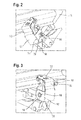
- FIGS. 2 and 3 show in mounting position the fuse element 50 according to the invention, which consists of a stamped sheet metal, preferably made of spring steel, in the in the Fig. 2 to 4 is shown bent shape.
- the fuse element 50 consists of an upper cover portion 52, a side cover portion 54, which, as in Fig. 2 to 4 is shown, even again in different, angularly arranged to each other sub-areas can be divided, as well as a first securing area 56 and a second securing area 58.
- the upper covering area 52 is arranged substantially horizontally in the installed position.
- the lateral covering region 54 extends substantially vertically and is connected in one piece with the upper covering region 52 via a bending region 60.
- the first securing region 56 and the second securing region 58 are each parallel to one another and are likewise arranged vertically in the installed position.
- the first securing region and the second securing region are each perpendicular to the lateral covering region 54, but are also perpendicular to the upper covering region 52.
- the first securing region 56 and the second securing region 58 are each integrally connected to the lateral covering region 54 via the bending seams 62 and 64.
- In the region of the first securing region 56 there is an opening 66, through which the head 38 of the eccentric pin 22 can pass.
- Lock washer 34 shown is covered by the first securing portion 56, so that the eccentric pin 22 is secured against slipping out in the axial direction.
- the second securing portion 58 has a recess 68 which is arranged and shaped to prevent the fastening nut 28 from rotating.
- a fastening nut 28 as in Fig. 1 shown, is used, ie, a fastening nut, which in addition has a circular flange portion, the over the circular flange arranged securing element 50 also represents an additional backup in the axial direction.
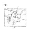
- Fig. 4 For example, the upper cover portion 52 of the fuse element 50 is shown.
- the in Fig. 4 invisible tongue fastening screw which is only partly in Fig. 4 visible circlip 70 which is disposed around the head of the tongue attachment screw around and through a locking screw 72 screwed into the tongue block is prevented from rotating and secured against unintentional loosening.
- the tongue fastening screw can thus not emerge upwards out of the tongue block as a result of the upper covering area 52 arranged above it in the vertical direction.
- a rotation is prevented by the retaining ring 72, which in turn is prevented by the fixing screw 72 from undesired rotation.
- a covering tongue 74 is provided which is arranged and dimensioned so that it presses elastically against the head of the fixing screw 72, so that the fixing screw can not be unscrewed upwards out of the tongue block.
- a fixing pin 76 is shown in plan view, which extends from the head of the tongue fastening screw, not shown, upwards and extends through a dimensioned according to the dimensions of the pin receiving opening 78 in the region of the upper cover 52.
- the fixing pin 76 serves to position the securing element 50, so that in addition to the opening 66 for the head 38 of the eccentric pin in the region of the first securing portion 56 and adjacent to the recess 68 for positive reception of the fastening nut 28, a third fixing point is still present Secured fuse element 50 in position.
- the locking plate thus fulfills a variety of tasks. It secures the eccentric pin against falling out, but also secures the shim of the eccentric bolt and furthermore also the self-locking fastening nut of the eccentric bolt against unscrewing. Finally, the securing element also protects against the ingress of dirt from behind and up in the switch clamp.
Landscapes
- Engineering & Computer Science (AREA)
- Mechanical Engineering (AREA)
- Connection Of Plates (AREA)
- Fuses (AREA)
- Surgical Instruments (AREA)
Applications Claiming Priority (1)
| Application Number | Priority Date | Filing Date | Title |
|---|---|---|---|
| DE102011086077A DE102011086077A1 (de) | 2011-11-10 | 2011-11-10 | Sicherungselement für einen Klammerverschluss für ein Weichenstellsystem |
Publications (3)
| Publication Number | Publication Date |
|---|---|
| EP2591972A2 true EP2591972A2 (fr) | 2013-05-15 |
| EP2591972A3 EP2591972A3 (fr) | 2016-03-02 |
| EP2591972B1 EP2591972B1 (fr) | 2017-01-04 |
Family
ID=47225997
Family Applications (1)
| Application Number | Title | Priority Date | Filing Date |
|---|---|---|---|
| EP12191810.6A Active EP2591972B1 (fr) | 2011-11-10 | 2012-11-08 | Élément de sécurisation pour une fermeture à ressort pour un système d'aiguillage |
Country Status (6)
| Country | Link |
|---|---|
| EP (1) | EP2591972B1 (fr) |
| DE (1) | DE102011086077A1 (fr) |
| DK (1) | DK2591972T5 (fr) |
| ES (1) | ES2620852T3 (fr) |
| PL (1) | PL2591972T3 (fr) |
| PT (1) | PT2591972T (fr) |
Cited By (1)
| Publication number | Priority date | Publication date | Assignee | Title |
|---|---|---|---|---|
| EP3693246A1 (fr) * | 2019-02-05 | 2020-08-12 | Siemens Mobility AG | Dispositif de réglage d'aiguillage doté d'un c ur d'aiguillage mobile |
Citations (1)
| Publication number | Priority date | Publication date | Assignee | Title |
|---|---|---|---|---|
| EP1020341B1 (fr) | 1999-01-13 | 2002-05-02 | Siemens Schweiz AG (Siemens Suisse SA) (Siemens Svizzera SA) Siemens Switzerland Ltd) | Dispositif de sécurité pour système de manoeuvre d' aiguilles |
Family Cites Families (3)
| Publication number | Priority date | Publication date | Assignee | Title |
|---|---|---|---|---|
| DE547034C (de) * | 1932-07-23 | Alois Rolf | Vorrichtung zum Verschliessen von Eisenbahnweichenspitzenverschluessen | |
| DE2400628A1 (de) * | 1974-01-08 | 1975-07-17 | Schwaebische Huettenwerke Gmbh | Klammerspitzenverschluss fuer weichen aus regelschienen |
| ATE352465T1 (de) * | 2002-07-03 | 2007-02-15 | Siemens Schweiz Ag | Exzenterbolzen für weichenverschlüsse |
-
2011
- 2011-11-10 DE DE102011086077A patent/DE102011086077A1/de not_active Ceased
-
2012
- 2012-11-08 PT PT121918106T patent/PT2591972T/pt unknown
- 2012-11-08 EP EP12191810.6A patent/EP2591972B1/fr active Active
- 2012-11-08 ES ES12191810.6T patent/ES2620852T3/es active Active
- 2012-11-08 PL PL12191810T patent/PL2591972T3/pl unknown
- 2012-11-08 DK DK12191810.6T patent/DK2591972T5/en active
Patent Citations (1)
| Publication number | Priority date | Publication date | Assignee | Title |
|---|---|---|---|---|
| EP1020341B1 (fr) | 1999-01-13 | 2002-05-02 | Siemens Schweiz AG (Siemens Suisse SA) (Siemens Svizzera SA) Siemens Switzerland Ltd) | Dispositif de sécurité pour système de manoeuvre d' aiguilles |
Cited By (1)
| Publication number | Priority date | Publication date | Assignee | Title |
|---|---|---|---|---|
| EP3693246A1 (fr) * | 2019-02-05 | 2020-08-12 | Siemens Mobility AG | Dispositif de réglage d'aiguillage doté d'un c ur d'aiguillage mobile |
Also Published As
| Publication number | Publication date |
|---|---|
| DE102011086077A1 (de) | 2013-05-16 |
| EP2591972A3 (fr) | 2016-03-02 |
| DK2591972T3 (en) | 2017-02-13 |
| PT2591972T (pt) | 2017-02-10 |
| PL2591972T3 (pl) | 2017-09-29 |
| EP2591972B1 (fr) | 2017-01-04 |
| DK2591972T5 (en) | 2017-04-03 |
| ES2620852T3 (es) | 2017-06-29 |
Similar Documents
| Publication | Publication Date | Title |
|---|---|---|
| EP2971354B1 (fr) | Fixation de rails comprenant un raccordement par clipsage entre la plaque de guidage et la plaque de base | |
| EP2634347B1 (fr) | Support de verre, agencement de profilé et construction de cadre | |
| EP2812199B1 (fr) | Fixation de suspension pneumatique | |
| DE19544580C1 (de) | Lenkradbefestigung | |
| EP1269564A1 (fr) | Dispositif de fixation d'une antenne de vehicule automobile | |
| EP3828039B1 (fr) | Dispositif de support pour une pièce de revêtement extérieur d'un véhicule automobile | |
| EP2591972B1 (fr) | Élément de sécurisation pour une fermeture à ressort pour un système d'aiguillage | |
| DE10217534A1 (de) | Verriegelungseinrichtung von Einstelleinrichtungen für Lenksäulen von Kraftfahrzeugen | |
| EP3326249B1 (fr) | Agencement comprenant une partie haute de toit et un système de fixation pour la fixation de la partie haute de toit sur le toit d'une armoire électrique | |
| DE102009024531A1 (de) | Verbindungselement und eine über das Verbindungselement gebildete Baueinheit | |
| DE2724333C3 (de) | Vorrichtung zum Sichern von Schraubverbindungen | |
| EP1388674B1 (fr) | Dispositif de fixation d'un sabot de ligne de conduite | |
| EP1903219B1 (fr) | Dispositif pour la fixation d'un composant sur un élément de support | |
| DE102014102856B3 (de) | Federgesicherte Befestigungseinrichtung für einen Sicherheitsgurtbeschlag | |
| EP0685373B1 (fr) | Dispositif de réglage en hauteur d'un renvoi de ceinture de sécurité pour véhicules | |
| EP2700766B1 (fr) | Dispositif de fixation de façade | |
| EP3402993B1 (fr) | Systeme de montage dote de rail de montage et ecrou de retenue en saillie | |
| DE102015104856B4 (de) | Einrichtung zur Sicherung der Befestigung eines Gitarrengurtes an mindestens einem am Gitarrenkörper angebrachten Gurtpin | |
| DE102018122701A1 (de) | Haltersystem zur Befestigung eines Behälters an einem Fahrzeug | |
| DE102018003567A1 (de) | Vorrichtung zum Verstellen eines Sturzes und/ oder einer Spur der Räder eines Fahrzeuges | |
| DE202011109417U1 (de) | Dachhaken zur Befestigung von Montageeinrichtungen | |
| AT399206B (de) | Halter | |
| DE3143951A1 (de) | "kombinierte dreh- und verschiebesicherung fuer einen bolzen" | |
| EP3239537B1 (fr) | Dispositif de fixation et son procede de fabrication | |
| DE9011077U1 (de) | Drehmomentstütze für das Antriebsaggregat eines Kraftfahrzeuges |
Legal Events
| Date | Code | Title | Description |
|---|---|---|---|
| PUAI | Public reference made under article 153(3) epc to a published international application that has entered the european phase |
Free format text: ORIGINAL CODE: 0009012 |
|
| AK | Designated contracting states |
Kind code of ref document: A2 Designated state(s): AL AT BE BG CH CY CZ DE DK EE ES FI FR GB GR HR HU IE IS IT LI LT LU LV MC MK MT NL NO PL PT RO RS SE SI SK SM TR |
|
| AX | Request for extension of the european patent |
Extension state: BA ME |
|
| PUAL | Search report despatched |
Free format text: ORIGINAL CODE: 0009013 |
|
| AK | Designated contracting states |
Kind code of ref document: A3 Designated state(s): AL AT BE BG CH CY CZ DE DK EE ES FI FR GB GR HR HU IE IS IT LI LT LU LV MC MK MT NL NO PL PT RO RS SE SI SK SM TR |
|
| AX | Request for extension of the european patent |
Extension state: BA ME |
|
| RIC1 | Information provided on ipc code assigned before grant |
Ipc: B61L 5/10 20060101AFI20160125BHEP |
|
| 17P | Request for examination filed |
Effective date: 20160617 |
|
| RBV | Designated contracting states (corrected) |
Designated state(s): AL AT BE BG CH CY CZ DE DK EE ES FI FR GB GR HR HU IE IS IT LI LT LU LV MC MK MT NL NO PL PT RO RS SE SI SK SM TR |
|
| GRAP | Despatch of communication of intention to grant a patent |
Free format text: ORIGINAL CODE: EPIDOSNIGR1 |
|
| INTG | Intention to grant announced |
Effective date: 20161005 |
|
| GRAS | Grant fee paid |
Free format text: ORIGINAL CODE: EPIDOSNIGR3 |
|
| GRAA | (expected) grant |
Free format text: ORIGINAL CODE: 0009210 |
|
| AK | Designated contracting states |
Kind code of ref document: B1 Designated state(s): AL AT BE BG CH CY CZ DE DK EE ES FI FR GB GR HR HU IE IS IT LI LT LU LV MC MK MT NL NO PL PT RO RS SE SI SK SM TR |
|
| REG | Reference to a national code |
Ref country code: GB Ref legal event code: FG4D Free format text: NOT ENGLISH |
|
| REG | Reference to a national code |
Ref country code: CH Ref legal event code: EP |
|
| REG | Reference to a national code |
Ref country code: AT Ref legal event code: REF Ref document number: 858909 Country of ref document: AT Kind code of ref document: T Effective date: 20170115 |
|
| REG | Reference to a national code |
Ref country code: IE Ref legal event code: FG4D Free format text: LANGUAGE OF EP DOCUMENT: GERMAN |
|
| REG | Reference to a national code |
Ref country code: PT Ref legal event code: SC4A Ref document number: 2591972 Country of ref document: PT Date of ref document: 20170210 Kind code of ref document: T Free format text: AVAILABILITY OF NATIONAL TRANSLATION Effective date: 20170131 |
|
| REG | Reference to a national code |
Ref country code: DK Ref legal event code: T3 Effective date: 20170208 |
|
| REG | Reference to a national code |
Ref country code: NL Ref legal event code: FP |
|
| REG | Reference to a national code |
Ref country code: DE Ref legal event code: R096 Ref document number: 502012009198 Country of ref document: DE |
|
| REG | Reference to a national code |
Ref country code: SE Ref legal event code: TRGR |
|
| REG | Reference to a national code |
Ref country code: NO Ref legal event code: T2 Effective date: 20170104 |
|
| REG | Reference to a national code |
Ref country code: DK Ref legal event code: T5 Effective date: 20170329 |
|
| REG | Reference to a national code |
Ref country code: LT Ref legal event code: MG4D |
|
| REG | Reference to a national code |
Ref country code: ES Ref legal event code: FG2A Ref document number: 2620852 Country of ref document: ES Kind code of ref document: T3 Effective date: 20170629 |
|
| PG25 | Lapsed in a contracting state [announced via postgrant information from national office to epo] |
Ref country code: LT Free format text: LAPSE BECAUSE OF FAILURE TO SUBMIT A TRANSLATION OF THE DESCRIPTION OR TO PAY THE FEE WITHIN THE PRESCRIBED TIME-LIMIT Effective date: 20170104 Ref country code: FI Free format text: LAPSE BECAUSE OF FAILURE TO SUBMIT A TRANSLATION OF THE DESCRIPTION OR TO PAY THE FEE WITHIN THE PRESCRIBED TIME-LIMIT Effective date: 20170104 Ref country code: IS Free format text: LAPSE BECAUSE OF FAILURE TO SUBMIT A TRANSLATION OF THE DESCRIPTION OR TO PAY THE FEE WITHIN THE PRESCRIBED TIME-LIMIT Effective date: 20170504 Ref country code: GR Free format text: LAPSE BECAUSE OF FAILURE TO SUBMIT A TRANSLATION OF THE DESCRIPTION OR TO PAY THE FEE WITHIN THE PRESCRIBED TIME-LIMIT Effective date: 20170405 Ref country code: HR Free format text: LAPSE BECAUSE OF FAILURE TO SUBMIT A TRANSLATION OF THE DESCRIPTION OR TO PAY THE FEE WITHIN THE PRESCRIBED TIME-LIMIT Effective date: 20170104 |
|
| PG25 | Lapsed in a contracting state [announced via postgrant information from national office to epo] |
Ref country code: LV Free format text: LAPSE BECAUSE OF FAILURE TO SUBMIT A TRANSLATION OF THE DESCRIPTION OR TO PAY THE FEE WITHIN THE PRESCRIBED TIME-LIMIT Effective date: 20170104 Ref country code: RS Free format text: LAPSE BECAUSE OF FAILURE TO SUBMIT A TRANSLATION OF THE DESCRIPTION OR TO PAY THE FEE WITHIN THE PRESCRIBED TIME-LIMIT Effective date: 20170104 Ref country code: BG Free format text: LAPSE BECAUSE OF FAILURE TO SUBMIT A TRANSLATION OF THE DESCRIPTION OR TO PAY THE FEE WITHIN THE PRESCRIBED TIME-LIMIT Effective date: 20170404 |
|
| REG | Reference to a national code |
Ref country code: DE Ref legal event code: R097 Ref document number: 502012009198 Country of ref document: DE |
|
| PG25 | Lapsed in a contracting state [announced via postgrant information from national office to epo] |
Ref country code: EE Free format text: LAPSE BECAUSE OF FAILURE TO SUBMIT A TRANSLATION OF THE DESCRIPTION OR TO PAY THE FEE WITHIN THE PRESCRIBED TIME-LIMIT Effective date: 20170104 Ref country code: CZ Free format text: LAPSE BECAUSE OF FAILURE TO SUBMIT A TRANSLATION OF THE DESCRIPTION OR TO PAY THE FEE WITHIN THE PRESCRIBED TIME-LIMIT Effective date: 20170104 Ref country code: SK Free format text: LAPSE BECAUSE OF FAILURE TO SUBMIT A TRANSLATION OF THE DESCRIPTION OR TO PAY THE FEE WITHIN THE PRESCRIBED TIME-LIMIT Effective date: 20170104 Ref country code: RO Free format text: LAPSE BECAUSE OF FAILURE TO SUBMIT A TRANSLATION OF THE DESCRIPTION OR TO PAY THE FEE WITHIN THE PRESCRIBED TIME-LIMIT Effective date: 20170104 |
|
| PLBE | No opposition filed within time limit |
Free format text: ORIGINAL CODE: 0009261 |
|
| STAA | Information on the status of an ep patent application or granted ep patent |
Free format text: STATUS: NO OPPOSITION FILED WITHIN TIME LIMIT |
|
| PG25 | Lapsed in a contracting state [announced via postgrant information from national office to epo] |
Ref country code: SM Free format text: LAPSE BECAUSE OF FAILURE TO SUBMIT A TRANSLATION OF THE DESCRIPTION OR TO PAY THE FEE WITHIN THE PRESCRIBED TIME-LIMIT Effective date: 20170104 |
|
| 26N | No opposition filed |
Effective date: 20171005 |
|
| PG25 | Lapsed in a contracting state [announced via postgrant information from national office to epo] |
Ref country code: SI Free format text: LAPSE BECAUSE OF FAILURE TO SUBMIT A TRANSLATION OF THE DESCRIPTION OR TO PAY THE FEE WITHIN THE PRESCRIBED TIME-LIMIT Effective date: 20170104 |
|
| PG25 | Lapsed in a contracting state [announced via postgrant information from national office to epo] |
Ref country code: MC Free format text: LAPSE BECAUSE OF FAILURE TO SUBMIT A TRANSLATION OF THE DESCRIPTION OR TO PAY THE FEE WITHIN THE PRESCRIBED TIME-LIMIT Effective date: 20170104 |
|
| REG | Reference to a national code |
Ref country code: FR Ref legal event code: ST Effective date: 20180731 |
|
| REG | Reference to a national code |
Ref country code: IE Ref legal event code: MM4A |
|
| PG25 | Lapsed in a contracting state [announced via postgrant information from national office to epo] |
Ref country code: MT Free format text: LAPSE BECAUSE OF FAILURE TO SUBMIT A TRANSLATION OF THE DESCRIPTION OR TO PAY THE FEE WITHIN THE PRESCRIBED TIME-LIMIT Effective date: 20170104 |
|
| PG25 | Lapsed in a contracting state [announced via postgrant information from national office to epo] |
Ref country code: FR Free format text: LAPSE BECAUSE OF NON-PAYMENT OF DUE FEES Effective date: 20171130 Ref country code: IE Free format text: LAPSE BECAUSE OF NON-PAYMENT OF DUE FEES Effective date: 20171108 |
|
| PG25 | Lapsed in a contracting state [announced via postgrant information from national office to epo] |
Ref country code: HU Free format text: LAPSE BECAUSE OF FAILURE TO SUBMIT A TRANSLATION OF THE DESCRIPTION OR TO PAY THE FEE WITHIN THE PRESCRIBED TIME-LIMIT; INVALID AB INITIO Effective date: 20121108 |
|
| PG25 | Lapsed in a contracting state [announced via postgrant information from national office to epo] |
Ref country code: CY Free format text: LAPSE BECAUSE OF NON-PAYMENT OF DUE FEES Effective date: 20170104 |
|
| PG25 | Lapsed in a contracting state [announced via postgrant information from national office to epo] |
Ref country code: MK Free format text: LAPSE BECAUSE OF FAILURE TO SUBMIT A TRANSLATION OF THE DESCRIPTION OR TO PAY THE FEE WITHIN THE PRESCRIBED TIME-LIMIT Effective date: 20170104 |
|
| PG25 | Lapsed in a contracting state [announced via postgrant information from national office to epo] |
Ref country code: AL Free format text: LAPSE BECAUSE OF FAILURE TO SUBMIT A TRANSLATION OF THE DESCRIPTION OR TO PAY THE FEE WITHIN THE PRESCRIBED TIME-LIMIT Effective date: 20170104 |
|
| PGFP | Annual fee paid to national office [announced via postgrant information from national office to epo] |
Ref country code: NL Payment date: 20231113 Year of fee payment: 12 Ref country code: LU Payment date: 20231113 Year of fee payment: 12 |
|
| PGFP | Annual fee paid to national office [announced via postgrant information from national office to epo] |
Ref country code: GB Payment date: 20231115 Year of fee payment: 12 |
|
| PGFP | Annual fee paid to national office [announced via postgrant information from national office to epo] |
Ref country code: ES Payment date: 20231201 Year of fee payment: 12 |
|
| PGFP | Annual fee paid to national office [announced via postgrant information from national office to epo] |
Ref country code: TR Payment date: 20231019 Year of fee payment: 12 Ref country code: SE Payment date: 20231031 Year of fee payment: 12 Ref country code: PT Payment date: 20231020 Year of fee payment: 12 Ref country code: NO Payment date: 20231124 Year of fee payment: 12 Ref country code: IT Payment date: 20231115 Year of fee payment: 12 Ref country code: DK Payment date: 20231115 Year of fee payment: 12 Ref country code: DE Payment date: 20231106 Year of fee payment: 12 Ref country code: CH Payment date: 20231201 Year of fee payment: 12 Ref country code: AT Payment date: 20231128 Year of fee payment: 12 |
|
| PGFP | Annual fee paid to national office [announced via postgrant information from national office to epo] |
Ref country code: PL Payment date: 20231030 Year of fee payment: 12 Ref country code: BE Payment date: 20231113 Year of fee payment: 12 |