EP2591972A2 - Securing element for a clamp lock for a points positioning system - Google Patents
Securing element for a clamp lock for a points positioning system Download PDFInfo
- Publication number
- EP2591972A2 EP2591972A2 EP12191810.6A EP12191810A EP2591972A2 EP 2591972 A2 EP2591972 A2 EP 2591972A2 EP 12191810 A EP12191810 A EP 12191810A EP 2591972 A2 EP2591972 A2 EP 2591972A2
- Authority
- EP
- European Patent Office
- Prior art keywords
- securing
- tongue
- upper cover
- region
- fastening
- Prior art date
- Legal status (The legal status is an assumption and is not a legal conclusion. Google has not performed a legal analysis and makes no representation as to the accuracy of the status listed.)
- Granted
Links
- 238000005452 bending Methods 0.000 claims description 5
- 239000002184 metal Substances 0.000 claims description 4
- 229910000639 Spring steel Inorganic materials 0.000 claims description 3
- 210000002105 tongue Anatomy 0.000 description 59
- 230000006870 function Effects 0.000 description 4
- 230000009993 protective function Effects 0.000 description 2
- 238000005266 casting Methods 0.000 description 1
- 238000011109 contamination Methods 0.000 description 1
- 238000006073 displacement reaction Methods 0.000 description 1
- 230000037431 insertion Effects 0.000 description 1
- 238000003780 insertion Methods 0.000 description 1
- 238000009434 installation Methods 0.000 description 1
Images

Classifications
-
- B—PERFORMING OPERATIONS; TRANSPORTING
- B61—RAILWAYS
- B61L—GUIDING RAILWAY TRAFFIC; ENSURING THE SAFETY OF RAILWAY TRAFFIC
- B61L5/00—Local operating mechanisms for points or track-mounted scotch-blocks; Visible or audible signals; Local operating mechanisms for visible or audible signals
- B61L5/10—Locking mechanisms for points; Means for indicating the setting of points
Definitions
- the invention relates to a securing element for a tongue block of a clip closure for a points system.
- a point setting system two setting tongues are moved, depending on the given direction of travel, such that one of the two setting tongues is in contact with the associated stock rail, while the other setting tongue is located at a suitable distance, the so-called tongue surcharge, from the associated other stock rail.
- the simultaneous control of the point locks of a points setting system is done via a slide rod, which cooperates with closing clips and opens and locks the points closure.
- the closure clip is pivoted about a horizontal axis on a tongue block.
- the tongue block is also connected via a screw with the Stellzunge.
- an eccentric bolt requires that the stroke of the eccentric pin can be adjusted in graduated steps via a suitable adjustment element, such as a dial.
- a suitable adjustment element such as a dial.
- the exact position of the positioning tongue relative to the tongue block is designed adjustable.
- the setting components for switch locks must be easily accessible. However, this requires that the risk of contamination is given.
- high safety standards must be met. One of these is that the adjustment and fastening components in the area of tongue clamps can not be released automatically. For this reason, a solution is sought to increase the reliability of the point setting system.
- a securing device for switch systems which consists in the form of a formed of a metal plate securing cap, which secures the provided for the connection of the adjusting tongue with the tongue clamp screw against automatic loosening.
- the invention has for its object to provide a securing element for a tongue block of a staple closure for a point system, which allows increased reliability of the point system even at high mechanical load and very long time of use of point control system.
- the locking element for a tongue block of a clip closure for a points system comprises an upper cover portion with a securing portion for securing against unscrewing the tongue fastening screw between the positioning tab and tongue block, arranged substantially perpendicular to the upper cover, in the installed position substantially vertically oriented, and integrally with the upper cover formed side cover portion, and a first securing portion and a second securing portion, which are each arranged parallel to each other and formed integrally with the lateral cover portion.
- Each fuse portion is oriented perpendicular to the side cover portion and the upper cover portion and spaced from the upper cover portion, and each securing portion secures a bolt connection for attaching a locking bracket to the tongue block against accidental release.
- the adjusting components on the tongue block namely, the tongue fixing screw for fixing the adjusting tongue and the bolt connection for securing the locking clip
- the fuse element has a double function in this regard. It is itself actively a protective function for the tongue fastening screw and the locking bolt, but fulfills the additional protective function that additional security elements can also be fixed in position.
- Another advantage of the fuse element is the simple geometry, which makes it possible according to a preferred embodiment of the invention to produce the fuse element from a flat sheet metal stamping and bring by bending in the desired shape.
- the securing element consists of spring steel, which combines high hardness, strength and elasticity in itself.
- the securing element is dimensioned and designed such that the first securing area secures an eccentric bolt for fastening the closing clip on the tongue block against falling out.
- the first securing portion is designed so that the eccentric pin is prevented from axial movement opposite to the insertion direction during assembly. This can be done by a complete coverage of a widened head of the eccentric bolt or even by a positive connection with another element is produced, which in turn is positively connected to the eccentric pin. In the specific case, this may be a dial, which cooperates with the head of the eccentric pin to set a desired stroke within the existing adjustment of the eccentric bolt by a targeted, sectionwise rotation.
- the securing element is dimensioned and designed such that the second securing region secures against rotation an attachment nut fixed on an eccentric bolt for fastening the closure clip to the tongue clamp.
- This can take place in that the second securing area is provided with a star-shaped opening, which surrounds the fastening nut, so that at most a rotation of the fastening nut in a very narrow and thus with respect to the unintentional release the eccentric bolt safe angle range can be done.
- the upper cover portion is dimensioned to fix a retaining ring around the head of the tongue fastening screw in the vertical direction.
- the clip fastener there is provided an additional circlip around the head of the tongue-fixing screw, which is prevented from passing over the upper cover portion from engaging the head of the tongue-fixing screw in the vertical direction.
- the securing element further comprises a covering tongue in the region of the upper covering area, which secures a fixing screw provided for preventing the rotation of the securing ring from falling out.
- a complete securing of the tongue fixing screw can be achieved in this way.
- the tongue fixing screw can not be rotated out of the tongue block in the vertical direction, as this prevents the upper cover portion of the securing element.
- the tongue fixing screw can not be turned to any appreciable extent because the locking ring around the head of the tongue fixing screw is prevented from rotating by the fixing screw.
- the locking ring can not come out of engagement with the head of the tongue fastening screw in the vertical direction.
- the fixing screw for fixing the securing ring in the direction of rotation is protected against falling out in the vertical direction by the covering tongue in the region of the upper covering area of the securing element.
- the securing element further comprises an opening in the upper cover area, which is dimensioned and arranged so that in the installed position extends from the head of the tongue fastening screw upwardly projecting pin through the opening. In this way, the securing element is held in a particularly simple manner in the correct position.
- a tongue block 10 is shown as well as some components associated with the tongue clamp.
- the tongue block 10 is usually designed as a casting.
- a receiving slot 12 for the foot of the positioning tongue the example in Fig. 2 shown and designated reference numeral 14.
- aligned bores 16 are provided for receiving a tongue fastening screw.
- the longitudinal axis of in Fig. 1 Tongue fixing screw, not shown, is substantially vertical in the installation position of the tongue block 10 on a positioning tongue.
- a closure clip 18 which has a fastening eye 20, by means of which the closure clip 18 can be fastened to the tongue block 10.
- the eccentric bolt passes through the attachment eye 20 of the closure clip 18 and can be used with its eccentric region 24 by a targeted rotation for adjusting the closure clip 18.
- the eccentric pin 22 passes through mutually aligned receiving openings 26 on the tongue block 10 and in particular two legs of the tongue block, between which the closing clip 18 is arranged.
- a fastening nut 28 which is preferably carried out self-locking. Another security against falling out provides a Sich ceremoniesssplint 30 which is passed through the split opening 32 on the eccentric pin 22 and secured by bending against falling out.
- a shim 34 is attached in a form-fitting manner, which is provided with a keyhole-shaped opening.
- the substantially round part of the keyhole-shaped opening 36 serves to be placed over the head 38 of the eccentric pin can.
- a subsequent displacement in the axial direction from the substantially circular region of the opening 36 out fixes the locking washer 34 in a form-fitting manner in cooperation with the groove 40, so that the locking washer 34 is fixed in the axial direction of the eccentric pin and only together with the eccentric pin to the Longitudinal axis of the eccentric pin can be rotated around.
- the lock washer 34 is provided with a number of pin openings 42 which receive in the installed position with the fixing pin, which prevents rotation of the lock washer and, together with the lock washer of the eccentric pin.
- Fig. 1 is still a catch pin 46 shown, which is secured over the split pin 48 on an axial falling out and only has the function to enclose the existing in a conventional Weichenstellsystem slide rod below the closure clip 18, so that the tongue block is not up out of engagement with the slide rod can be moved out.
- the function of the catch bolt is irrelevant to the understanding of the present invention.
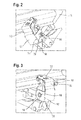
- FIGS. 2 and 3 show in mounting position the fuse element 50 according to the invention, which consists of a stamped sheet metal, preferably made of spring steel, in the in the Fig. 2 to 4 is shown bent shape.
- the fuse element 50 consists of an upper cover portion 52, a side cover portion 54, which, as in Fig. 2 to 4 is shown, even again in different, angularly arranged to each other sub-areas can be divided, as well as a first securing area 56 and a second securing area 58.
- the upper covering area 52 is arranged substantially horizontally in the installed position.
- the lateral covering region 54 extends substantially vertically and is connected in one piece with the upper covering region 52 via a bending region 60.
- the first securing region 56 and the second securing region 58 are each parallel to one another and are likewise arranged vertically in the installed position.
- the first securing region and the second securing region are each perpendicular to the lateral covering region 54, but are also perpendicular to the upper covering region 52.
- the first securing region 56 and the second securing region 58 are each integrally connected to the lateral covering region 54 via the bending seams 62 and 64.
- In the region of the first securing region 56 there is an opening 66, through which the head 38 of the eccentric pin 22 can pass.
- Lock washer 34 shown is covered by the first securing portion 56, so that the eccentric pin 22 is secured against slipping out in the axial direction.
- the second securing portion 58 has a recess 68 which is arranged and shaped to prevent the fastening nut 28 from rotating.
- a fastening nut 28 as in Fig. 1 shown, is used, ie, a fastening nut, which in addition has a circular flange portion, the over the circular flange arranged securing element 50 also represents an additional backup in the axial direction.
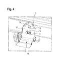
- Fig. 4 For example, the upper cover portion 52 of the fuse element 50 is shown.
- the in Fig. 4 invisible tongue fastening screw which is only partly in Fig. 4 visible circlip 70 which is disposed around the head of the tongue attachment screw around and through a locking screw 72 screwed into the tongue block is prevented from rotating and secured against unintentional loosening.
- the tongue fastening screw can thus not emerge upwards out of the tongue block as a result of the upper covering area 52 arranged above it in the vertical direction.
- a rotation is prevented by the retaining ring 72, which in turn is prevented by the fixing screw 72 from undesired rotation.
- a covering tongue 74 is provided which is arranged and dimensioned so that it presses elastically against the head of the fixing screw 72, so that the fixing screw can not be unscrewed upwards out of the tongue block.
- a fixing pin 76 is shown in plan view, which extends from the head of the tongue fastening screw, not shown, upwards and extends through a dimensioned according to the dimensions of the pin receiving opening 78 in the region of the upper cover 52.
- the fixing pin 76 serves to position the securing element 50, so that in addition to the opening 66 for the head 38 of the eccentric pin in the region of the first securing portion 56 and adjacent to the recess 68 for positive reception of the fastening nut 28, a third fixing point is still present Secured fuse element 50 in position.
- the locking plate thus fulfills a variety of tasks. It secures the eccentric pin against falling out, but also secures the shim of the eccentric bolt and furthermore also the self-locking fastening nut of the eccentric bolt against unscrewing. Finally, the securing element also protects against the ingress of dirt from behind and up in the switch clamp.
Landscapes
- Engineering & Computer Science (AREA)
- Mechanical Engineering (AREA)
- Connection Of Plates (AREA)
- Fuses (AREA)
- Surgical Instruments (AREA)
Abstract
Description
Die Erfindung betrifft ein Sicherungselement für einen Zungenkloben eines Klammerverschlusses für ein Weichenstellsystem.The invention relates to a securing element for a tongue block of a clip closure for a points system.
In einem Weichenstellsystem werden je nach vorgegebener Fahrrichtung zwei Stellzungen so bewegt, dass sich eine der beiden Stellzungen in Kontakt zur zugehörigen Backenschiene befindet, während sich die andere Stellzunge in einem geeigneten Abstand, dem sogenannten Zungenaufschlag, von der zugehörigen anderen Backenschiene entfernt befindet. Die gleichzeitige Steuerung der Weichenverschlüsse eines Weichenstellsystems geschieht über eine Schieberstange, die mit Verschlussklammern zusammenwirkt und den Weichenverschluss öffnet bzw. verriegelt. Bei einem vertikalen Klammerverschluss wird die Verschlussklammer um eine horizontale Achse an einem Zungenkloben verschwenkt. Der Zungenkloben ist zudem über eine Schraubbefestigung mit der Stellzunge verbunden. Um die einzelnen Komponenten eines wie oben beschriebenen Weichenstellsystems exakt justieren zu können, ist es im Stand der Technik bekannt, die Verschlussklammer über einen Exzenterbolzen am Zungenkloben schwenkbar zu befestigen. Die Verwendung eines Exzenterbolzens bedingt, dass über ein geeignetes Einstellelement, wie z.B. eine Einstellscheibe, der Hub des Exzenterbolzens in abgestuften Schritten eingestellt werden kann. Auch die genaue Position der Stellzunge relativ zum Zungenkloben ist einstellbar gestaltet. Damit die Komponenten während des Betriebs überprüft und gegebenenfalls nachjustiert werden können, müssen die Einstellkomponenten für Weichenschlösser leicht zugänglich sein. Dies bedingt allerdings, dass die Gefahr einer Verschmutzung gegeben ist. Weiterhin sind hohe Sicherheitsstandards zu erfüllen. Zu diesen gehört auch, dass sich die Einstell- und Befestigungskomponenten im Bereich Zungenklobens nicht selbsttätig lösen können. Aus diesem Grund wird eine Lösung gesucht, um die Betriebssicherheit des Weichenstellsystems zu erhöhen.In a point setting system, two setting tongues are moved, depending on the given direction of travel, such that one of the two setting tongues is in contact with the associated stock rail, while the other setting tongue is located at a suitable distance, the so-called tongue surcharge, from the associated other stock rail. The simultaneous control of the point locks of a points setting system is done via a slide rod, which cooperates with closing clips and opens and locks the points closure. In a vertical clip closure, the closure clip is pivoted about a horizontal axis on a tongue block. The tongue block is also connected via a screw with the Stellzunge. In order to be able to precisely adjust the individual components of a point adjustment system as described above, it is known in the prior art to use the closure clip via an eccentric pin on the tongue block pivotally attach. The use of an eccentric bolt requires that the stroke of the eccentric pin can be adjusted in graduated steps via a suitable adjustment element, such as a dial. The exact position of the positioning tongue relative to the tongue block is designed adjustable. In order for the components to be checked during operation and, if necessary, readjusted, the setting components for switch locks must be easily accessible. However, this requires that the risk of contamination is given. Furthermore, high safety standards must be met. One of these is that the adjustment and fastening components in the area of tongue clamps can not be released automatically. For this reason, a solution is sought to increase the reliability of the point setting system.
Aus der
Der Erfindung liegt die Aufgabe zugrunde, ein Sicherungselement für einen Zungenkloben eines Klammerverschlusses für ein Weichenstellsystem vorzuschlagen, das eine erhöhte Betriebssicherheit des Weichenstellsystems auch bei hoher mechanischer Belastung und sehr langer Einsatzzeit des Weichenstellsystems ermöglicht.The invention has for its object to provide a securing element for a tongue block of a staple closure for a point system, which allows increased reliability of the point system even at high mechanical load and very long time of use of point control system.
Diese Aufgabe wird durch ein Sicherungselement mit den Merkmalen des Anspruchs 1 gelöst. Bevorzugte Ausführungsformen folgen aus den übrigen Ansprüchen.This object is achieved by a securing element having the features of claim 1. Preferred embodiments follow from the remaining claims.
Das Sicherungselement für einen Zungenkloben eines Klammerverschlusses für ein Weichenstellsystem umfasst einen oberen Abdeckbereich mit einem Sicherungsabschnitt zur Sicherung gegen Herausdrehen der Zungenbefestigungsschraube zwischen Stellzunge und Zungenkloben, einen im Wesentlichen senkrecht zum oberen Abdeckbereich angeordneten, in Einbaulage im Wesentlichen vertikal orientierten, sowie einstückig mit dem oberen Abdeckbereich ausgebildeten seitlichen Abdeckbereich, und einen ersten Sicherungsbereich und einen zweiten Sicherungsbereich, die jeweils parallel zueinander angeordnet und einstückig mit dem seitlichen Abdeckbereich ausgebildet sind. Jeder Sicherungsbereich ist senkrecht zum seitlichen Abdeckbereich sowie zum oberen Abdeckbereich ausgerichtet und vom oberen Abdeckbereich beabstandet, und jeder Sicherungsbereich sichert eine Bolzenverbindung zur Befestigung einer Verschlussklammer am Zungenkloben gegen unbeabsichtigtes Lösen.The locking element for a tongue block of a clip closure for a points system comprises an upper cover portion with a securing portion for securing against unscrewing the tongue fastening screw between the positioning tab and tongue block, arranged substantially perpendicular to the upper cover, in the installed position substantially vertically oriented, and integrally with the upper cover formed side cover portion, and a first securing portion and a second securing portion, which are each arranged parallel to each other and formed integrally with the lateral cover portion. Each fuse portion is oriented perpendicular to the side cover portion and the upper cover portion and spaced from the upper cover portion, and each securing portion secures a bolt connection for attaching a locking bracket to the tongue block against accidental release.
Indem das Sicherungselement einen oberen Abdeckbereich, einen seitlichem Abdeckbereich und zwei Sicherungsbereiche aufweist, können die Einstellkomponenten am Zungenkloben, nämlich die Zungenbefestigungsschraube zur Befestigung der Stellzunge und die Bolzenverbindung zur Befestigung der Verschlussklammer gegen Herausfallen gesichert werden. Somit werden sämtliche kritischen Einzelkomponenten über das Sicherungselement nach der Erfindung geschützt. Da zusätzlich zu Sicherungselement noch separate Sicherheitsvorkehrungen zur Lagefixierung der Zungenbefestigungsschraube sowie des Bolzens zur Befestigung der Verschlussklammer vorgesehen sein können, wird die Betriebssicherheit des Weichenstellsystems erheblich erhöht. Das Sicherungselement hat diesbezüglich eine Doppelfunktion. Es stellt selbst aktiv eine Schutzfunktion für die Zungenbefestigungsschraube und den Verschlussklammerbolzen dar, erfüllt aber die zusätzliche Schutzfunktion, dass zusätzliche Sicherheitselemente ebenfalls lagefixiert werden können. Ein weiterer Vorteil des Sicherungselements ist die einfache Geometrie, die es nach einer bevorzugten Ausführungsform der Erfindung ermöglicht, das Sicherungselement aus einem flächigen Blechstanzteil herzustellen und durch Biegen in die gewünschte Form zu bringen.By having the securing member having an upper cover portion, a side cover portion, and two securing portions, the adjusting components on the tongue block, namely, the tongue fixing screw for fixing the adjusting tongue and the bolt connection for securing the locking clip, can be prevented from falling out. Thus, all critical individual components are protected by the fuse element according to the invention. Since, in addition to securing element, separate safety precautions for fixing the position of the tongue fastening screw and of the bolt for fastening the closing clip can be provided, the operational reliability of the point setting system is considerably increased. The fuse element has a double function in this regard. It is itself actively a protective function for the tongue fastening screw and the locking bolt, but fulfills the additional protective function that additional security elements can also be fixed in position. Another advantage of the fuse element is the simple geometry, which makes it possible according to a preferred embodiment of the invention to produce the fuse element from a flat sheet metal stamping and bring by bending in the desired shape.
Vorzugsweise besteht das Sicherungselement aus Federstahl, der hohe Härte, Festigkeit und Elastizität in sich vereint.Preferably, the securing element consists of spring steel, which combines high hardness, strength and elasticity in itself.
Nach einer bevorzugten Ausführungsform der Erfindung ist das Sicherungselement so dimensioniert und gestaltet, dass der erste Sicherungsbereich einen Exzenterbolzen zur Befestigung der Verschlussklammer am Zungenkloben gegen Herausfallen sichert. Zu diesem Zweck ist der erste Sicherungsbereich so gestaltet, dass der Exzenterbolzen an einer Axialbewegung entgegengesetzt zur Einführrichtung bei der Montage gehindert wird. Dies kann durch eine vollständige Abdeckung eines verbreiterten Kopfes des Exzenterbolzens erfolgen oder aber auch indem eine formschlüssige Verbindung mit einem anderen Element hergestellt wird, das wiederum formschlüssig mit dem Exzenterbolzen verbunden ist. Im konkreten Fall kann dies eine Einstellscheibe sein, die mit dem Kopf des Exzenterbolzens zusammen wirkt, um durch eine gezielte, abschnittsweise Drehung einen gewünschten Hub innerhalb des vorhandenen Verstellbereichs des Exzenterbolzens einzustellen.According to a preferred embodiment of the invention, the securing element is dimensioned and designed such that the first securing area secures an eccentric bolt for fastening the closing clip on the tongue block against falling out. For this purpose, the first securing portion is designed so that the eccentric pin is prevented from axial movement opposite to the insertion direction during assembly. This can be done by a complete coverage of a widened head of the eccentric bolt or even by a positive connection with another element is produced, which in turn is positively connected to the eccentric pin. In the specific case, this may be a dial, which cooperates with the head of the eccentric pin to set a desired stroke within the existing adjustment of the eccentric bolt by a targeted, sectionwise rotation.
Vorzugsweise ist das Sicherungselement so dimensioniert und gestaltet, dass der zweite Sicherungsbereich eine auf einen Exzenterbolzen zur Befestigung der Verschlussklammer am Zungenkloben fixierte Befestigungsmutter gegen Verdrehen sichert. Dies kann dadurch erfolgen, dass der zweite Sicherungsbereich mit einer sternförmigen Öffnung versehen ist, welche die Befestigungsmutter umgreift, so dass allenfalls eine Verdrehung der Befestigungsmutter in einem sehr engen und damit in Bezug auf das unbeabsichtigte Lösen des Exzenterbolzens ungefährlichen Winkelbereich erfolgen kann.Preferably, the securing element is dimensioned and designed such that the second securing region secures against rotation an attachment nut fixed on an eccentric bolt for fastening the closure clip to the tongue clamp. This can take place in that the second securing area is provided with a star-shaped opening, which surrounds the fastening nut, so that at most a rotation of the fastening nut in a very narrow and thus with respect to the unintentional release the eccentric bolt safe angle range can be done.
Nach einer bevorzugten Ausführungsform der Erfindung ist der obere Abdeckbereich dimensioniert, um einen Sicherungsring um den Kopf der Zungenbefestigungsschraube in vertikaler Richtung zu fixieren. Es ist somit bei dem Klammerverschluss ein zusätzlicher Sicherungsring um den Kopf der Zungenbefestigungsschraube vorgesehen, der über den oberen Abdeckbereich daran gehindert wird, in vertikaler Richtung aus dem Eingriff mit dem Kopf der Zungenbefestigungsschraube zu gelangen.According to a preferred embodiment of the invention, the upper cover portion is dimensioned to fix a retaining ring around the head of the tongue fastening screw in the vertical direction. Thus, in the clip fastener, there is provided an additional circlip around the head of the tongue-fixing screw, which is prevented from passing over the upper cover portion from engaging the head of the tongue-fixing screw in the vertical direction.
Vorzugsweise umfasst das Sicherungselement weiterhin eine Abdeckzunge im Bereich des oberen Abdeckbereichs, welche eine zur Verhinderung der Drehung des Sicherungsrings vorgesehene Fixierschraube gegen Herausfallen sichert. In Zusammenwirken mit der oben genannten Dimensionierung des oberen Abdeckbereichs, so dass der um den Kopf der Zungenbefestigungsschraube angeordnete Sicherungsring nicht in vertikaler Richtung aus dem Eingriff mit dem Kopf der Zungenbefestigungsschraube gelangen kann, lässt sich auf diese Weise eine vollständige Sicherung der Zungenbefestigungsschraube erreichen. Die Zungenbefestigungsschraube kann nicht in vertikaler Richtung aus dem Zungenkloben herausgedreht werden, da dies der obere Abdeckbereich des Sicherungselements verhindert. Die Zungenbefestigungsschraube kann auch nicht in nennenswertem Umfang gedreht werden, weil der Sicherungsring um den Kopf der Zungenbefestigungsschraube durch die Fixierschraube an einer Drehung gehindert wird. Außerdem kann der Sicherungsring nicht in vertikaler Richtung aus dem Eingriff mit dem Kopf der Zungenbefestigungsschraube kommen. Schließlich ist die Fixierschraube zur Fixierung des Sicherungsrings in Rotationsrichtung gegen ein Herausfallen in vertikaler Richtung durch die Abdeckzunge im Bereich des oberen Abdeckbereichs des Sicherungselements geschützt.Preferably, the securing element further comprises a covering tongue in the region of the upper covering area, which secures a fixing screw provided for preventing the rotation of the securing ring from falling out. In cooperation with the above-mentioned dimensioning of the upper cover area, so that the circlip arranged around the head of the tongue fixing screw can not come out of engagement with the head of the tongue fixing screw in the vertical direction, a complete securing of the tongue fixing screw can be achieved in this way. The tongue fixing screw can not be rotated out of the tongue block in the vertical direction, as this prevents the upper cover portion of the securing element. Also, the tongue fixing screw can not be turned to any appreciable extent because the locking ring around the head of the tongue fixing screw is prevented from rotating by the fixing screw. In addition, the locking ring can not come out of engagement with the head of the tongue fastening screw in the vertical direction. Finally, the fixing screw for fixing the securing ring in the direction of rotation is protected against falling out in the vertical direction by the covering tongue in the region of the upper covering area of the securing element.
Nach einer bevorzugten Ausführungsform der Erfindung umfasst das Sicherungselement weiterhin eine Öffnung im oberen Abdeckbereich, die dimensioniert und angeordnet ist, dass sich in Einbaulage ein vom Kopf der Zungenbefestigungsschraube nach oben ragender Zapfen durch die Öffnung erstreckt. Auf diese Weise wird das Sicherungselement auf eine besonders einfache Weise in der richtigen Lage gehalten.According to a preferred embodiment of the invention, the securing element further comprises an opening in the upper cover area, which is dimensioned and arranged so that in the installed position extends from the head of the tongue fastening screw upwardly projecting pin through the opening. In this way, the securing element is held in a particularly simple manner in the correct position.
Nachfolgend wird die Erfindung rein beispielhaft anhand der beigefügten Figuren beschrieben, in denen
- Fig. 1
- eine Explosionsdarstellung eines Zungenklobens und damit verbundener Bauteile in einem Weichenstellsystem darstellt. Um die einzelnen Bauteile und deren Funktion besser darstellen zu können, wurde bewusst das erfindungsgemäße Sicherungselement nicht dargestellt.
- Fig. 2
- zeigt eine erste Darstellung der erfindungsgemäßen Sicherungselements in Einbaulage in einem Weichenstellsystem;
- Fig. 3
- zeigt eine zweite Darstellung der erfindungsgemäßen Sicherungselements in Einbaulage in einem Weichenstellsystem; und
- Fig. 4
- zeigt das in den
Figuren 2 und 3 dargestellte Sicherungselement mit Blick auf den oberen Abdeckbereich.
- Fig. 1
- an exploded view of a tongue block and associated components in a points system represents. In order to better represent the individual components and their function, the fuse element according to the invention was deliberately not shown.
- Fig. 2
- shows a first representation of the securing element according to the invention in the installed position in a point setting system;
- Fig. 3
- shows a second view of the securing element according to the invention in the installed position in a point setting system; and
- Fig. 4
- shows that in the
FIGS. 2 and 3 illustrated fuse element overlooking the upper cover area.
In den nachfolgenden Figuren werden dieselben Bauelemente jeweils mit denselben Referenzziffern bezeichnet.In the following figures, the same components are denoted by the same reference numerals.
In
In
Im Bereich des Kopfes des Exzenterbolzens wird formschlüssig eine Einstellscheibe 34 angebracht, die mit einer schlüssellochförmigen Öffnung versehen ist. Der im Wesentlichen runde Teil der schlüssellochförmigen Öffnung 36 dient dazu, über den Kopf 38 des Exzenterbolzens gesteckt werden zu können. Eine anschließende Verschiebung in axialer Richtung aus dem im Wesentlichen kreisförmigen Bereich der Öffnung 36 heraus fixiert die Sicherungsscheibe 34 in formschlüssiger Weise in Zusammenwirken mit der Nut 40, so dass die Sicherungsscheibe 34 in axialer richtung des Exzenterbolzens fixiert ist und nur gemeinsam mit dem Exzenterbolzen um die Längsachse des Exzenterbolzens herum gedreht werden kann. Die Sicherungsscheibe 34 ist mit einer Anzahl von Stiftöffnungen 42 versehen, die in Einbauposition mit dem Fixierstift aufnehmen, der ein Verdrehen der Sicherungsscheibe und, gemeinsam mit der Sicherungsscheibe des Exzenterbolzens, verhindert.In the region of the head of the eccentric bolt, a
In
In
In
Das Sicherungsblech erfüllt somit eine Vielzahl von Aufgaben. Es sichert den Exzenterbolzen gegen Herausfallen, sichert aber zusätzlich auch die Einstellscheibe des Exzenterbolzens und weiterhin auch die selbstsichernde Befestigungsmutter des Exzenterbolzens gegen Herausdrehen. Schließlich schützt das Sicherungselement auch gegen das Eindringen von Schmutz von hinten und oben in die Weichenklammer.The locking plate thus fulfills a variety of tasks. It secures the eccentric pin against falling out, but also secures the shim of the eccentric bolt and furthermore also the self-locking fastening nut of the eccentric bolt against unscrewing. Finally, the securing element also protects against the ingress of dirt from behind and up in the switch clamp.
Claims (8)
umfassend:
full:
dadurch gekennzeichnet, dass
das Sicherungselement (50) durch Biegen eines flächigen Blechstanzteils hergestellt ist.Securing element (50) according to claim 1,
characterized in that
the securing element (50) is produced by bending a sheet-metal stamped part.
dadurch gekennzeichnet, dass
das Sicherungselement (50) aus Federstahl besteht.Securing element (50) according to claim 1 or claim 2,
characterized in that
the securing element (50) consists of spring steel.
dadurch gekennzeichnet, dass
das Sicherungselement (50) so dimensioniert und gestaltet ist, dass der erste Sicherungsbereich (56) einen Exzenterbolzen (22) zur Befestigung der Verschlussklammer (18) am Zungenkloben (10) gegen Herausfallen sichert.Fuse element (50) according to one of the preceding claims,
characterized in that
the securing element (50) is dimensioned and designed so that the first securing area (56) secures an eccentric bolt (22) for fastening the closing clip (18) on the tongue block (10) against falling out.
dadurch gekennzeichnet, dass
das Sicherungselement (50) so dimensioniert und gestaltet ist, dass der zweite Sicherungsbereich (58) eine auf einem Exzenterbolzen (22) zur Befestigung der Verschlussklammer (18) am Zungenkloben (10) fixierte Befestigungsmutter (28) gegen Verdrehen sichert.Fuse element (50) according to one of the preceding claims,
characterized in that
the securing element (50) is dimensioned and designed such that the second securing region (58) secures a fastening nut (28) fixed on an eccentric bolt (22) for fastening the closing clip (18) to the tongue block (10) against rotation.
dadurch gekennzeichnet, dass
das der obere Abdeckbereich (52) dimensioniert ist, um einen Sicherungsring (70) um den Kopf der Zungenbefestigungsschraube in vertikaler Richtung zu fixieren.Fuse element (50) according to one of the preceding claims,
characterized in that
the upper cover portion (52) is dimensioned to fix a circlip (70) about the head of the tongue fixing screw in the vertical direction.
Applications Claiming Priority (1)
| Application Number | Priority Date | Filing Date | Title |
|---|---|---|---|
| DE102011086077A DE102011086077A1 (en) | 2011-11-10 | 2011-11-10 | Securing element for a clip closure for a points system |
Publications (3)
| Publication Number | Publication Date |
|---|---|
| EP2591972A2 true EP2591972A2 (en) | 2013-05-15 |
| EP2591972A3 EP2591972A3 (en) | 2016-03-02 |
| EP2591972B1 EP2591972B1 (en) | 2017-01-04 |
Family
ID=47225997
Family Applications (1)
| Application Number | Title | Priority Date | Filing Date |
|---|---|---|---|
| EP12191810.6A Active EP2591972B1 (en) | 2011-11-10 | 2012-11-08 | Securing element for a clamp lock for a points positioning system |
Country Status (6)
| Country | Link |
|---|---|
| EP (1) | EP2591972B1 (en) |
| DE (1) | DE102011086077A1 (en) |
| DK (1) | DK2591972T5 (en) |
| ES (1) | ES2620852T3 (en) |
| PL (1) | PL2591972T3 (en) |
| PT (1) | PT2591972T (en) |
Cited By (1)
| Publication number | Priority date | Publication date | Assignee | Title |
|---|---|---|---|---|
| EP3693246A1 (en) * | 2019-02-05 | 2020-08-12 | Siemens Mobility AG | Points adjustment device with movable frog |
Citations (1)
| Publication number | Priority date | Publication date | Assignee | Title |
|---|---|---|---|---|
| EP1020341B1 (en) | 1999-01-13 | 2002-05-02 | Siemens Schweiz AG (Siemens Suisse SA) (Siemens Svizzera SA) Siemens Switzerland Ltd) | Security device for points operating system |
Family Cites Families (3)
| Publication number | Priority date | Publication date | Assignee | Title |
|---|---|---|---|---|
| DE547034C (en) * | 1932-07-23 | Alois Rolf | Device for locking railway point closures | |
| DE2400628A1 (en) * | 1974-01-08 | 1975-07-17 | Schwaebische Huettenwerke Gmbh | Railway switch points tongue clamp tip lock - has automatic tongue-setting change-compensating device incorporating slide bolt for hinge swivelling |
| ATE352465T1 (en) * | 2002-07-03 | 2007-02-15 | Siemens Schweiz Ag | ECCENTRIC BOLTS FOR POINT CLOSURES |
-
2011
- 2011-11-10 DE DE102011086077A patent/DE102011086077A1/en not_active Ceased
-
2012
- 2012-11-08 PT PT121918106T patent/PT2591972T/en unknown
- 2012-11-08 EP EP12191810.6A patent/EP2591972B1/en active Active
- 2012-11-08 ES ES12191810.6T patent/ES2620852T3/en active Active
- 2012-11-08 PL PL12191810T patent/PL2591972T3/en unknown
- 2012-11-08 DK DK12191810.6T patent/DK2591972T5/en active
Patent Citations (1)
| Publication number | Priority date | Publication date | Assignee | Title |
|---|---|---|---|---|
| EP1020341B1 (en) | 1999-01-13 | 2002-05-02 | Siemens Schweiz AG (Siemens Suisse SA) (Siemens Svizzera SA) Siemens Switzerland Ltd) | Security device for points operating system |
Cited By (1)
| Publication number | Priority date | Publication date | Assignee | Title |
|---|---|---|---|---|
| EP3693246A1 (en) * | 2019-02-05 | 2020-08-12 | Siemens Mobility AG | Points adjustment device with movable frog |
Also Published As
| Publication number | Publication date |
|---|---|
| DE102011086077A1 (en) | 2013-05-16 |
| EP2591972A3 (en) | 2016-03-02 |
| DK2591972T3 (en) | 2017-02-13 |
| PT2591972T (en) | 2017-02-10 |
| PL2591972T3 (en) | 2017-09-29 |
| EP2591972B1 (en) | 2017-01-04 |
| DK2591972T5 (en) | 2017-04-03 |
| ES2620852T3 (en) | 2017-06-29 |
Similar Documents
| Publication | Publication Date | Title |
|---|---|---|
| EP2971354B1 (en) | Rail fastening system comprising a snap-fit connection between the guide plate and the base plate | |
| EP2634347B1 (en) | Glass holder, profile assembly and frame construction | |
| EP2812199B1 (en) | Air spring fastening | |
| DE19544580C1 (en) | Steering wheel attachment | |
| EP1269564A1 (en) | Device for fixing a vehicle antenna | |
| EP3828039B1 (en) | Support device for an external cladding section of a motor vehicle | |
| EP2591972B1 (en) | Securing element for a clamp lock for a points positioning system | |
| DE10217534A1 (en) | Locking device for steering column adjuster unit in motor vehicles has locking part moved by control unit at right angles to clamping position, when tooth tips of locking and counter parts are in contact in blocking position | |
| EP3326249B1 (en) | Arrangement comprising a roof system and a fastening system for the fastening of the roof system on the roof of an electrical cabinet | |
| DE102009024531A1 (en) | Connection element i.e. C-shaped clip nut, for connecting side impact beam and frame of door body of motor vehicle, has screw nut whose front end sealingly rests against flange section of passage opening in mounting position of nut | |
| DE2724333C3 (en) | Device for securing screw connections | |
| EP1388674B1 (en) | Retaining device for the shoe of a pipe line | |
| EP1903219B1 (en) | Fastening device for fastening a component to a support part | |
| DE102014102856B3 (en) | Spring-resistant fastening device for a safety belt fitting | |
| EP0685373B1 (en) | Adjustable shoulder anchorage for a vehicle seat belt system | |
| EP2700766B1 (en) | Façade attachment device | |
| EP3402993B1 (en) | Mounting assembly with a mounting rail and protruding retaining nut | |
| DE102015104856B4 (en) | Device for securing the fastening of a guitar strap to at least one belt pin attached to the guitar body | |
| DE102018122701A1 (en) | Holder system for attaching a container to a vehicle | |
| DE102018003567A1 (en) | Device for adjusting a fall and / or a track of the wheels of a vehicle | |
| DE202011109417U1 (en) | Roof hook for fastening mounting devices | |
| AT399206B (en) | HOLDER | |
| DE3143951A1 (en) | Combined anti-rotation and anti-displacement safeguard for a bolt | |
| EP3239537B1 (en) | Fixing device and method for its manufacture | |
| DE9011077U1 (en) | Torque support for the drive unit of a motor vehicle |
Legal Events
| Date | Code | Title | Description |
|---|---|---|---|
| PUAI | Public reference made under article 153(3) epc to a published international application that has entered the european phase |
Free format text: ORIGINAL CODE: 0009012 |
|
| AK | Designated contracting states |
Kind code of ref document: A2 Designated state(s): AL AT BE BG CH CY CZ DE DK EE ES FI FR GB GR HR HU IE IS IT LI LT LU LV MC MK MT NL NO PL PT RO RS SE SI SK SM TR |
|
| AX | Request for extension of the european patent |
Extension state: BA ME |
|
| PUAL | Search report despatched |
Free format text: ORIGINAL CODE: 0009013 |
|
| AK | Designated contracting states |
Kind code of ref document: A3 Designated state(s): AL AT BE BG CH CY CZ DE DK EE ES FI FR GB GR HR HU IE IS IT LI LT LU LV MC MK MT NL NO PL PT RO RS SE SI SK SM TR |
|
| AX | Request for extension of the european patent |
Extension state: BA ME |
|
| RIC1 | Information provided on ipc code assigned before grant |
Ipc: B61L 5/10 20060101AFI20160125BHEP |
|
| 17P | Request for examination filed |
Effective date: 20160617 |
|
| RBV | Designated contracting states (corrected) |
Designated state(s): AL AT BE BG CH CY CZ DE DK EE ES FI FR GB GR HR HU IE IS IT LI LT LU LV MC MK MT NL NO PL PT RO RS SE SI SK SM TR |
|
| GRAP | Despatch of communication of intention to grant a patent |
Free format text: ORIGINAL CODE: EPIDOSNIGR1 |
|
| INTG | Intention to grant announced |
Effective date: 20161005 |
|
| GRAS | Grant fee paid |
Free format text: ORIGINAL CODE: EPIDOSNIGR3 |
|
| GRAA | (expected) grant |
Free format text: ORIGINAL CODE: 0009210 |
|
| AK | Designated contracting states |
Kind code of ref document: B1 Designated state(s): AL AT BE BG CH CY CZ DE DK EE ES FI FR GB GR HR HU IE IS IT LI LT LU LV MC MK MT NL NO PL PT RO RS SE SI SK SM TR |
|
| REG | Reference to a national code |
Ref country code: GB Ref legal event code: FG4D Free format text: NOT ENGLISH |
|
| REG | Reference to a national code |
Ref country code: CH Ref legal event code: EP |
|
| REG | Reference to a national code |
Ref country code: AT Ref legal event code: REF Ref document number: 858909 Country of ref document: AT Kind code of ref document: T Effective date: 20170115 |
|
| REG | Reference to a national code |
Ref country code: IE Ref legal event code: FG4D Free format text: LANGUAGE OF EP DOCUMENT: GERMAN |
|
| REG | Reference to a national code |
Ref country code: PT Ref legal event code: SC4A Ref document number: 2591972 Country of ref document: PT Date of ref document: 20170210 Kind code of ref document: T Free format text: AVAILABILITY OF NATIONAL TRANSLATION Effective date: 20170131 |
|
| REG | Reference to a national code |
Ref country code: DK Ref legal event code: T3 Effective date: 20170208 |
|
| REG | Reference to a national code |
Ref country code: NL Ref legal event code: FP |
|
| REG | Reference to a national code |
Ref country code: DE Ref legal event code: R096 Ref document number: 502012009198 Country of ref document: DE |
|
| REG | Reference to a national code |
Ref country code: SE Ref legal event code: TRGR |
|
| REG | Reference to a national code |
Ref country code: NO Ref legal event code: T2 Effective date: 20170104 |
|
| REG | Reference to a national code |
Ref country code: DK Ref legal event code: T5 Effective date: 20170329 |
|
| REG | Reference to a national code |
Ref country code: LT Ref legal event code: MG4D |
|
| REG | Reference to a national code |
Ref country code: ES Ref legal event code: FG2A Ref document number: 2620852 Country of ref document: ES Kind code of ref document: T3 Effective date: 20170629 |
|
| PG25 | Lapsed in a contracting state [announced via postgrant information from national office to epo] |
Ref country code: LT Free format text: LAPSE BECAUSE OF FAILURE TO SUBMIT A TRANSLATION OF THE DESCRIPTION OR TO PAY THE FEE WITHIN THE PRESCRIBED TIME-LIMIT Effective date: 20170104 Ref country code: FI Free format text: LAPSE BECAUSE OF FAILURE TO SUBMIT A TRANSLATION OF THE DESCRIPTION OR TO PAY THE FEE WITHIN THE PRESCRIBED TIME-LIMIT Effective date: 20170104 Ref country code: IS Free format text: LAPSE BECAUSE OF FAILURE TO SUBMIT A TRANSLATION OF THE DESCRIPTION OR TO PAY THE FEE WITHIN THE PRESCRIBED TIME-LIMIT Effective date: 20170504 Ref country code: GR Free format text: LAPSE BECAUSE OF FAILURE TO SUBMIT A TRANSLATION OF THE DESCRIPTION OR TO PAY THE FEE WITHIN THE PRESCRIBED TIME-LIMIT Effective date: 20170405 Ref country code: HR Free format text: LAPSE BECAUSE OF FAILURE TO SUBMIT A TRANSLATION OF THE DESCRIPTION OR TO PAY THE FEE WITHIN THE PRESCRIBED TIME-LIMIT Effective date: 20170104 |
|
| PG25 | Lapsed in a contracting state [announced via postgrant information from national office to epo] |
Ref country code: LV Free format text: LAPSE BECAUSE OF FAILURE TO SUBMIT A TRANSLATION OF THE DESCRIPTION OR TO PAY THE FEE WITHIN THE PRESCRIBED TIME-LIMIT Effective date: 20170104 Ref country code: RS Free format text: LAPSE BECAUSE OF FAILURE TO SUBMIT A TRANSLATION OF THE DESCRIPTION OR TO PAY THE FEE WITHIN THE PRESCRIBED TIME-LIMIT Effective date: 20170104 Ref country code: BG Free format text: LAPSE BECAUSE OF FAILURE TO SUBMIT A TRANSLATION OF THE DESCRIPTION OR TO PAY THE FEE WITHIN THE PRESCRIBED TIME-LIMIT Effective date: 20170404 |
|
| REG | Reference to a national code |
Ref country code: DE Ref legal event code: R097 Ref document number: 502012009198 Country of ref document: DE |
|
| PG25 | Lapsed in a contracting state [announced via postgrant information from national office to epo] |
Ref country code: EE Free format text: LAPSE BECAUSE OF FAILURE TO SUBMIT A TRANSLATION OF THE DESCRIPTION OR TO PAY THE FEE WITHIN THE PRESCRIBED TIME-LIMIT Effective date: 20170104 Ref country code: CZ Free format text: LAPSE BECAUSE OF FAILURE TO SUBMIT A TRANSLATION OF THE DESCRIPTION OR TO PAY THE FEE WITHIN THE PRESCRIBED TIME-LIMIT Effective date: 20170104 Ref country code: SK Free format text: LAPSE BECAUSE OF FAILURE TO SUBMIT A TRANSLATION OF THE DESCRIPTION OR TO PAY THE FEE WITHIN THE PRESCRIBED TIME-LIMIT Effective date: 20170104 Ref country code: RO Free format text: LAPSE BECAUSE OF FAILURE TO SUBMIT A TRANSLATION OF THE DESCRIPTION OR TO PAY THE FEE WITHIN THE PRESCRIBED TIME-LIMIT Effective date: 20170104 |
|
| PLBE | No opposition filed within time limit |
Free format text: ORIGINAL CODE: 0009261 |
|
| STAA | Information on the status of an ep patent application or granted ep patent |
Free format text: STATUS: NO OPPOSITION FILED WITHIN TIME LIMIT |
|
| PG25 | Lapsed in a contracting state [announced via postgrant information from national office to epo] |
Ref country code: SM Free format text: LAPSE BECAUSE OF FAILURE TO SUBMIT A TRANSLATION OF THE DESCRIPTION OR TO PAY THE FEE WITHIN THE PRESCRIBED TIME-LIMIT Effective date: 20170104 |
|
| 26N | No opposition filed |
Effective date: 20171005 |
|
| PG25 | Lapsed in a contracting state [announced via postgrant information from national office to epo] |
Ref country code: SI Free format text: LAPSE BECAUSE OF FAILURE TO SUBMIT A TRANSLATION OF THE DESCRIPTION OR TO PAY THE FEE WITHIN THE PRESCRIBED TIME-LIMIT Effective date: 20170104 |
|
| PG25 | Lapsed in a contracting state [announced via postgrant information from national office to epo] |
Ref country code: MC Free format text: LAPSE BECAUSE OF FAILURE TO SUBMIT A TRANSLATION OF THE DESCRIPTION OR TO PAY THE FEE WITHIN THE PRESCRIBED TIME-LIMIT Effective date: 20170104 |
|
| REG | Reference to a national code |
Ref country code: FR Ref legal event code: ST Effective date: 20180731 |
|
| REG | Reference to a national code |
Ref country code: IE Ref legal event code: MM4A |
|
| PG25 | Lapsed in a contracting state [announced via postgrant information from national office to epo] |
Ref country code: MT Free format text: LAPSE BECAUSE OF FAILURE TO SUBMIT A TRANSLATION OF THE DESCRIPTION OR TO PAY THE FEE WITHIN THE PRESCRIBED TIME-LIMIT Effective date: 20170104 |
|
| PG25 | Lapsed in a contracting state [announced via postgrant information from national office to epo] |
Ref country code: FR Free format text: LAPSE BECAUSE OF NON-PAYMENT OF DUE FEES Effective date: 20171130 Ref country code: IE Free format text: LAPSE BECAUSE OF NON-PAYMENT OF DUE FEES Effective date: 20171108 |
|
| PG25 | Lapsed in a contracting state [announced via postgrant information from national office to epo] |
Ref country code: HU Free format text: LAPSE BECAUSE OF FAILURE TO SUBMIT A TRANSLATION OF THE DESCRIPTION OR TO PAY THE FEE WITHIN THE PRESCRIBED TIME-LIMIT; INVALID AB INITIO Effective date: 20121108 |
|
| PG25 | Lapsed in a contracting state [announced via postgrant information from national office to epo] |
Ref country code: CY Free format text: LAPSE BECAUSE OF NON-PAYMENT OF DUE FEES Effective date: 20170104 |
|
| PG25 | Lapsed in a contracting state [announced via postgrant information from national office to epo] |
Ref country code: MK Free format text: LAPSE BECAUSE OF FAILURE TO SUBMIT A TRANSLATION OF THE DESCRIPTION OR TO PAY THE FEE WITHIN THE PRESCRIBED TIME-LIMIT Effective date: 20170104 |
|
| PG25 | Lapsed in a contracting state [announced via postgrant information from national office to epo] |
Ref country code: AL Free format text: LAPSE BECAUSE OF FAILURE TO SUBMIT A TRANSLATION OF THE DESCRIPTION OR TO PAY THE FEE WITHIN THE PRESCRIBED TIME-LIMIT Effective date: 20170104 |
|
| PGFP | Annual fee paid to national office [announced via postgrant information from national office to epo] |
Ref country code: NL Payment date: 20231113 Year of fee payment: 12 Ref country code: LU Payment date: 20231113 Year of fee payment: 12 |
|
| PGFP | Annual fee paid to national office [announced via postgrant information from national office to epo] |
Ref country code: GB Payment date: 20231115 Year of fee payment: 12 |
|
| PGFP | Annual fee paid to national office [announced via postgrant information from national office to epo] |
Ref country code: ES Payment date: 20231201 Year of fee payment: 12 |
|
| PGFP | Annual fee paid to national office [announced via postgrant information from national office to epo] |
Ref country code: TR Payment date: 20231019 Year of fee payment: 12 Ref country code: SE Payment date: 20231031 Year of fee payment: 12 Ref country code: PT Payment date: 20231020 Year of fee payment: 12 Ref country code: NO Payment date: 20231124 Year of fee payment: 12 Ref country code: IT Payment date: 20231115 Year of fee payment: 12 Ref country code: DK Payment date: 20231115 Year of fee payment: 12 Ref country code: DE Payment date: 20231106 Year of fee payment: 12 Ref country code: CH Payment date: 20231201 Year of fee payment: 12 Ref country code: AT Payment date: 20231128 Year of fee payment: 12 |
|
| PGFP | Annual fee paid to national office [announced via postgrant information from national office to epo] |
Ref country code: PL Payment date: 20231030 Year of fee payment: 12 Ref country code: BE Payment date: 20231113 Year of fee payment: 12 |