EP3326249B1 - Arrangement comprising a roof system and a fastening system for the fastening of the roof system on the roof of an electrical cabinet - Google Patents
Arrangement comprising a roof system and a fastening system for the fastening of the roof system on the roof of an electrical cabinet Download PDFInfo
- Publication number
- EP3326249B1 EP3326249B1 EP16754172.1A EP16754172A EP3326249B1 EP 3326249 B1 EP3326249 B1 EP 3326249B1 EP 16754172 A EP16754172 A EP 16754172A EP 3326249 B1 EP3326249 B1 EP 3326249B1
- Authority
- EP
- European Patent Office
- Prior art keywords
- roof structure
- arrangement
- roof
- bolt
- pretensioning device
- Prior art date
- Legal status (The legal status is an assumption and is not a legal conclusion. Google has not performed a legal analysis and makes no representation as to the accuracy of the status listed.)
- Active
Links
- 238000007789 sealing Methods 0.000 claims description 6
- 230000000295 complement effect Effects 0.000 claims description 4
- 230000006835 compression Effects 0.000 claims description 3
- 238000007906 compression Methods 0.000 claims description 3
- 229910000639 Spring steel Inorganic materials 0.000 claims description 2
- 238000001816 cooling Methods 0.000 claims description 2
- 239000000463 material Substances 0.000 claims 1
- 238000009434 installation Methods 0.000 description 2
- 230000002093 peripheral effect Effects 0.000 description 2
- 238000010276 construction Methods 0.000 description 1
- 230000001419 dependent effect Effects 0.000 description 1
- 238000006073 displacement reaction Methods 0.000 description 1
- 230000000694 effects Effects 0.000 description 1
- 210000003746 feather Anatomy 0.000 description 1
- 239000012858 resilient material Substances 0.000 description 1
- 239000007787 solid Substances 0.000 description 1
Images

Classifications
-
- H—ELECTRICITY
- H02—GENERATION; CONVERSION OR DISTRIBUTION OF ELECTRIC POWER
- H02B—BOARDS, SUBSTATIONS OR SWITCHING ARRANGEMENTS FOR THE SUPPLY OR DISTRIBUTION OF ELECTRIC POWER
- H02B1/00—Frameworks, boards, panels, desks, casings; Details of substations or switching arrangements
- H02B1/01—Frameworks
- H02B1/012—Details of mechanical connections
-
- F—MECHANICAL ENGINEERING; LIGHTING; HEATING; WEAPONS; BLASTING
- F16—ENGINEERING ELEMENTS AND UNITS; GENERAL MEASURES FOR PRODUCING AND MAINTAINING EFFECTIVE FUNCTIONING OF MACHINES OR INSTALLATIONS; THERMAL INSULATION IN GENERAL
- F16B—DEVICES FOR FASTENING OR SECURING CONSTRUCTIONAL ELEMENTS OR MACHINE PARTS TOGETHER, e.g. NAILS, BOLTS, CIRCLIPS, CLAMPS, CLIPS OR WEDGES; JOINTS OR JOINTING
- F16B2/00—Friction-grip releasable fastenings
- F16B2/02—Clamps, i.e. with gripping action effected by positive means other than the inherent resistance to deformation of the material of the fastening
- F16B2/06—Clamps, i.e. with gripping action effected by positive means other than the inherent resistance to deformation of the material of the fastening external, i.e. with contracting action
- F16B2/065—Clamps, i.e. with gripping action effected by positive means other than the inherent resistance to deformation of the material of the fastening external, i.e. with contracting action using screw-thread elements
-
- H—ELECTRICITY
- H02—GENERATION; CONVERSION OR DISTRIBUTION OF ELECTRIC POWER
- H02B—BOARDS, SUBSTATIONS OR SWITCHING ARRANGEMENTS FOR THE SUPPLY OR DISTRIBUTION OF ELECTRIC POWER
- H02B1/00—Frameworks, boards, panels, desks, casings; Details of substations or switching arrangements
- H02B1/26—Casings; Parts thereof or accessories therefor
- H02B1/30—Cabinet-type casings; Parts thereof or accessories therefor
-
- H—ELECTRICITY
- H02—GENERATION; CONVERSION OR DISTRIBUTION OF ELECTRIC POWER
- H02B—BOARDS, SUBSTATIONS OR SWITCHING ARRANGEMENTS FOR THE SUPPLY OR DISTRIBUTION OF ELECTRIC POWER
- H02B1/00—Frameworks, boards, panels, desks, casings; Details of substations or switching arrangements
- H02B1/56—Cooling; Ventilation
- H02B1/565—Cooling; Ventilation for cabinets
Definitions
- the invention relates to an arrangement of a roof structure, in particular a cooling device, and a fastening system for fastening the roof structure in a cutout on a roof of a cabinet.
- a roof structure in particular a cooling device
- a fastening system for fastening the roof structure in a cutout on a roof of a cabinet.
- Such an arrangement is known from DE 41 10 323 C1 known.
- Similar arrangements also show the EP 0 594 542 A1 and the DE 82 05 341 U1 ,
- the fastening system comprises a pretensioning device connected to the roof structure and a fastening clip, wherein the fastening clip has a fixed end, via which the fastening clip is fixed on an inner side of the roof structure, and an end movable relative to the fixed end, on which the pretensioning device engages, so that a radius of curvature of the mounting bracket on the biasing device is adjustable, wherein in a first position of the biasing device, the mounting bracket is adapted to engage under a boundary of a section and so define the roof structure on the one cabinet, and in a second Position of the biasing device, the mounting bracket is adapted to release the cutout, wherein the biasing device extends from an outer side of the roof structure through the roof structure through to an inner side of the roof structure, on the outside a first drive for a tool and on the inside a second drive for a tool.
- the first and the second drive can be, for example, screw drives, for example a Torx25 drive.
- a fastening system in which for the installation of the roof structure at a cutout in the roof of a cabinet, the roof structure can initially be done from the inside of the cabinet, which insofar a relief for the user is achieved because it requires no ladder or the like. If the control cabinet fills with components over time, or if the installation space of the control cabinet is so far occupied that the assembly or disassembly of the roof structure from the inside is no longer possible, the fastener previously actuated from the interior of the control cabinet can also be used from the outside of the control cabinet, more precisely from the roof side of the cabinet, are operated, the entire scope of functions of the fastening system is maintained.
- the biasing means may comprise a first pin with the first drive for a tool and a second pin with the second drive for a tool, wherein the bolts are rotatably connected to each other.
- the bolts may have complementary threads over which the bolts engage with each other, wherein the bolts for the rotationally fixed connection can be designed with each other. For example, they can be glued.
- one of the bolts has a bolt shank with an external thread, with which the bolt passes through a passage between an inside of the bolt Roof assembly and an outer side of the roof construction forming threaded sleeve extends with complementary internal thread therethrough, wherein the threaded sleeve is connected about its longitudinal axis against rotation with the roof structure.
- the threaded sleeve can thus form a threaded bearing for the bolt shaft, along which this rotationally adjustable different positions can take to adjust the mounting bracket, more precisely, its movable end variable.
- the second bolt may be formed as a sleeve nut, with a screw head having the second drive.
- the mounting bracket may have at the movable end a slot which extends along the mounting bracket in the direction of the fixed end, wherein one of the bolt extends with its bolt shank through the slot and the mounting bracket with an edge region of the slot on a bolt head of the second bolt supports, so that the bolt shaft is guided along the slot when the biasing device is moved between the first and the second position.
- the mounting bracket may be fixed with its fixed end on an inner side of the roof structure vertically above the cutout and spaced from an edge of the cutout on the inside of the roof structure, extending in the further course through the cutout into the cabinet interior and approach the edge of the cutout , In order to ensure the safe pivoting in and out of the mounting bracket, it can be provided that the biasing device is biased by a spring element in the second position.
- the mounting bracket may be formed of a resilient material and preferably made of spring steel, wherein the mounting bracket may further have a bias in the direction of the second position.
- the arrangement according to the invention makes it possible to rework the roof attachment, in particular retighten the attachment system, also at any time after attachment of the roof structure to the roof of the control cabinet.
- This can also be provided that the drive on the cabinet inside and the drive on the cabinet outside are identical, so that correspondingly identical tools can be used for the operation of the drive.
- the roof structure has a peripheral flange, via which the roof structure is placed on a boundary of the cutout of the control cabinet roof, wherein in a region of overlap between the peripheral flange and the edge, a sealing element is arranged, the compression of the biasing device variably adjustable is.
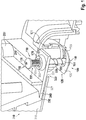
- FIG. 1 illustrated embodiment of a fastening system 100 for attachment of a roof structure 200 in or on a cutout 320 on the roof 310 of a cabinet 300
- the essential components of the fastening system 100, the associated with the roof structure 200 biasing device 110 and the mounting bracket 120, which via the biasing device 110 between a first position of the biasing device in which the mounting bracket 120 engages under a boundary 321 of the cutout 320 and thus defines the roof structure 200 to the control cabinet 300, and a second Position of the biasing device in which the mounting bracket releases the cutout, can be moved back and forth.
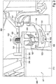
- the mounting bracket 120 has a fixed end 121, via which the mounting bracket 120 is fixed to the inside 220 of the roof structure 200.
- the mounting bracket 120 further includes a fixed end 121 opposite the fixed end 122 to which the biasing means acts, so that a curvature of the mounting bracket 120, and thus the position of the movable end 122 with respect to the edge 321 of the cutout 320, by pressing the biasing device 110 can be adjusted.
- the pretensioning device 110 has a bolt 150 with a bolt shaft 151, which in turn has an external thread 152, via which the bolt 150 is screwed into a threaded sleeve 170 with a complementary internal thread 171.
- the threaded sleeve 170 has a polygonal outer contour, via which it is accommodated at least in a form-fitting manner in a receptacle of the roof structure.
- the threaded sleeve 170 just forms a passage through the roof structure 200 and thus connects the outside 210 of the roof structure 200 with the inside 220 of the roof structure 200.
- a coil spring 180 is provided to pivot the mounting bracket 120 upon actuation of the actuator 130 whereby the bolt 150 is displaced relative to the sleeve 170.
- the mounting bracket 120 has at its movable end 122 has a slot 123 in which the shaft 151 of the bolt 150 is guided when the biasing means 110 is actuated to the mounting bracket from the in the FIGS. 1 and 2 shown release position in the in FIG. 3 to shift shown locking position.
- An encircling flange 230 of the roof structure 200 overlaps with an edge region 321 of the roof 310 of the control cabinet, wherein a sealing element 240 is arranged in the overlapping area. It can be seen that the fastening system according to the invention also has the advantage that it makes it possible to variably set the compression of the sealing element 240 and thus the sealing effect thereof via the pretensioning device 110.
- the second bolt 160 is formed as a sleeve nut, which is screwed onto an external thread of the upper bolt 150. With the sleeve nut and the bolt head 161 is fixed to the lower end of the bolt 150 to connect the mounting bracket 120 via the slot 123 with the biasing means.
- the bolt head 161 has just a bearing surface on which the mounting bracket 120 rests with the edge region of the slot 123.
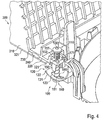
- FIG. 4 shows a further embodiment of the fastening system according to the invention, in which the threaded sleeve 170 is not inserted from above into a plastic tub, but is designed in the manner of a cage nut, which can be laterally inserted into a corresponding receptacle.
- the threaded sleeve is thus preferably rectangular and has a threaded receptacle.
Description
Die Erfindung betrifft eine Anordnung aus einem Dachaufbau, insbesondere einem Kühlgerät, und einem Befestigungssystem für die Befestigung des Dachaufbaus in einem Ausschnitt auf einem Dach eines Schaltschranks. Eine derartige Anordnung ist aus der
Bei den bisher bekannten Befestigungssystemen ist es stets vorgesehen, dass diese entweder nur von der Innenseite des Schaltschranks oder nur von der Außenseite des Schaltschranks betätigt werden können. Insbesondere dann, wenn der Innenraum des Schaltschranks noch nicht ausgebaut ist, ist es häufig wünschenswert, dass die Befestigung des Dachaufbaus von der Innenseite des Schaltschranks her erfolgen kann, damit für die Betätigung der Befestigungsmittel beispielsweise darauf verzichtet werden kann, dass der Schaltschrank mit einer Leiter oder dergleichen erklommen wird. Ist der Schaltschrank dann ausgebaut und soll beispielsweise der bereits montierte Dachaufbau verändert werden, kommt es vor, dass die Befestigungsmittel für den Dachaufbau von der Innenseite des Schaltschranks nur schwer zugänglich sind. In diesem Fall wäre es dann vorteilhaft gewesen, wenn der Dachaufbau mit Befestigungsmitteln befestigt worden wäre, die von der Außenseite des Schaltschranks her zugänglich sind.In the previously known fastening systems, it is always provided that they can be operated either only from the inside of the cabinet or only from the outside of the cabinet. In particular, when the interior of the cabinet is not removed, it is often desirable that the attachment of the roof structure can be done from the inside of the cabinet forth, so that for the operation of the fastening means can be dispensed, for example, that the cabinet with a ladder or the like is climbed. If the control cabinet is then removed and, for example, the already installed roof structure is to be changed, it happens that the fastening means for the roof structure are difficult to access from the inside of the control cabinet. In this case, it would have been advantageous if the roof structure would have been fastened with fastening means which are accessible from the outside of the cabinet.
Es ist daher die Aufgabe der Erfindung, eine Anordnung der eingangs beschriebenen Art vorzuschlagen, welche einfach zu bedienen ist und die sichere Festlegung eines Dachaufbaus an dem Schaltschrank ermöglicht.It is therefore an object of the invention to provide an arrangement of the type described above, which is easy to use and allows the secure determination of a roof structure on the cabinet.
Diese Aufgabe wird erfindungsgemäß durch eine Anordnung mit den Merkmalen des Anspruchs 1 gelöst. Die abhängigen Ansprüche betreffen jeweils vorteilhafte Ausführungsformen der Erfindung.This object is achieved by an arrangement with the features of claim 1. The dependent claims relate to advantageous embodiments of the invention.
Demgemäß weist das Befestigungssystem eine mit einem dem Dachaufbau verbundene Vorspanneinrichtung sowie eine Befestigungsklammer auf, wobei die Befestigungsklammer ein festes Ende, über das die Befestigungsklammer an einer Innenseite des Dachaufbaus festgelegt ist, und ein gegenüber dem festen Ende bewegliches Ende, an dem die Vorspanneinrichtung angreift, aufweist, so dass ein Krümmungsradius der Befestigungsklammer über die Vorspanneinrichtung einstellbar ist, wobei in einer ersten Stellung der Vorspanneinrichtung die Befestigungsklammer dazu eingerichtet ist, eine Berandung des eines Ausschnitts zu untergreifen und so den Dachaufbau an dem einem Schaltschrank festzulegen, und in einer zweiten Stellung der Vorspanneinrichtung die Befestigungsklammer dazu eingerichtet ist, den Ausschnitt freizugeben, wobei sich die Vorspanneinrichtung von einer Außenseite des Dachaufbaus durch den Dachaufbau hindurch bis zu einer Innenseite des Dachaufbaus erstreckt, an der Außenseite einen ersten Antrieb für ein Werkzeug und an der Innenseite einen zweiten Antrieb für ein Werkzeug aufweist.Accordingly, the fastening system comprises a pretensioning device connected to the roof structure and a fastening clip, wherein the fastening clip has a fixed end, via which the fastening clip is fixed on an inner side of the roof structure, and an end movable relative to the fixed end, on which the pretensioning device engages, so that a radius of curvature of the mounting bracket on the biasing device is adjustable, wherein in a first position of the biasing device, the mounting bracket is adapted to engage under a boundary of a section and so define the roof structure on the one cabinet, and in a second Position of the biasing device, the mounting bracket is adapted to release the cutout, wherein the biasing device extends from an outer side of the roof structure through the roof structure through to an inner side of the roof structure, on the outside a first drive for a tool and on the inside a second drive for a tool.
Der erste und der zweite Antrieb können beispielsweise Schraubenantriebe sein, beispielsweise ein Torx25-Antrieb.The first and the second drive can be, for example, screw drives, for example a Torx25 drive.
Dadurch wird ein Befestigungssystem erreicht, bei dem für die Montage des Dachaufbaus an einem Ausschnitt in dem Dach eines Schaltschranks der Dachaufbau zunächst von der Innenseite des Schaltschranks erfolgen kann, wodurch insofern eine Erleichterung für den Benutzer erreicht wird, da dieser keine Leiter oder dergleichen benötigt. Füllt sich der Schaltschrank im Laufe der Zeit mit Komponenten, oder ist der Bauraum des Schaltschranks so weit belegt, dass die Montage bzw. Demontage des Dachaufbaus von innen nicht mehr möglich ist, so kann der zuvor aus dem Schaltschrankinnern betätigte Befestiger auch von der Schaltschrankaußenseite, genauer von der Dachseite des Schaltschranks aus, betätigt werden, wobei der gesamte Funktionsumfang des Befestigungssystems erhalten bleibt.As a result, a fastening system is achieved, in which for the installation of the roof structure at a cutout in the roof of a cabinet, the roof structure can initially be done from the inside of the cabinet, which insofar a relief for the user is achieved because it requires no ladder or the like. If the control cabinet fills with components over time, or if the installation space of the control cabinet is so far occupied that the assembly or disassembly of the roof structure from the inside is no longer possible, the fastener previously actuated from the interior of the control cabinet can also be used from the outside of the control cabinet, more precisely from the roof side of the cabinet, are operated, the entire scope of functions of the fastening system is maintained.
Weiterhin kann die Vorspanneinrichtung einen ersten Bolzen mit dem ersten Antrieb für ein Werkzeug und einen zweiten Bolzen mit dem zweiten Antrieb für ein Werkzeug aufweisen, wobei die Bolzen drehfest miteinander verbunden sind. Dazu können die Bolzen komplementäre Gewinde aufweisen, über die die Bolzen ineinander greifen, wobei die Bolzen für die drehfeste Verbindung miteinander ausgelegt sein können. Sie können beispielsweise verklebt sein.Furthermore, the biasing means may comprise a first pin with the first drive for a tool and a second pin with the second drive for a tool, wherein the bolts are rotatably connected to each other. For this purpose, the bolts may have complementary threads over which the bolts engage with each other, wherein the bolts for the rotationally fixed connection can be designed with each other. For example, they can be glued.
Es ist ebenfalls denkbar, dass einer der Bolzen einen Bolzenschaft mit einem Außengewinde aufweist, mit dem sich der Bolzen durch eine einen Durchlass zwischen einer Innenseite des Dachaufbaus und einer Außenseite des Dachaufbaus bildende Gewindehülse mit komplementärem Innengewinde hindurch erstreckt, wobei die Gewindehülse um ihre Längsachse verdrehsicher mit dem Dachaufbau verbunden ist. Die Gewindehülse kann somit ein Gewindelager für den Bolzenschaft bilden, entlang welcher dieser drehverstellbar unterschiedliche Positionen einnehmen kann, um die Befestigungsklammer, genauer deren bewegliches Ende variabel zu verstellen.It is also conceivable that one of the bolts has a bolt shank with an external thread, with which the bolt passes through a passage between an inside of the bolt Roof assembly and an outer side of the roof construction forming threaded sleeve extends with complementary internal thread therethrough, wherein the threaded sleeve is connected about its longitudinal axis against rotation with the roof structure. The threaded sleeve can thus form a threaded bearing for the bolt shaft, along which this rotationally adjustable different positions can take to adjust the mounting bracket, more precisely, its movable end variable.
Der zweite Bolzen kann als eine Hülsenmutter ausgebildet sein, mit einem Schraubenkopf, der den zweiten Antrieb aufweist.The second bolt may be formed as a sleeve nut, with a screw head having the second drive.
Weiterhin kann die Befestigungsklammer an dem beweglichen Ende ein Langloch aufweisen, das sich entlang der Befestigungsklammer in Richtung des festen Endes erstreckt, wobei sich einer der Bolzen mit seinem Bolzenschaft durch das Langloch erstreckt und die Befestigungsklammer mit einem Randbereich des Langlochs an einem Bolzenkopf des zweiten Bolzens lagert, so dass der Bolzenschaft entlang des Langlochs geführt ist, wenn die Vorspanneinrichtung zwischen der ersten und der zweiten Stellung verstellt wird.Furthermore, the mounting bracket may have at the movable end a slot which extends along the mounting bracket in the direction of the fixed end, wherein one of the bolt extends with its bolt shank through the slot and the mounting bracket with an edge region of the slot on a bolt head of the second bolt supports, so that the bolt shaft is guided along the slot when the biasing device is moved between the first and the second position.
Die Befestigungsklammer kann mit ihrem festen Ende an einer Innenseite des Dachaufbaus vertikal oberhalb des Ausschnitts und beabstandet von einem Rand des Ausschnitts an der Innenseite des Dachaufbaus festgelegt sein, sich im weiteren Verlauf durch den Ausschnitt hindurch in den Schaltschrankinnenraum hinein erstrecken und dem Rand des Ausschnitts annähern. Um das sichere Ein- und Ausschwenken der Befestigungsklammer zu gewährleisten, kann vorgesehen sein, dass die Vorspanneinrichtung mit einem Federelement in die zweite Stellung vorgespannt ist.The mounting bracket may be fixed with its fixed end on an inner side of the roof structure vertically above the cutout and spaced from an edge of the cutout on the inside of the roof structure, extending in the further course through the cutout into the cabinet interior and approach the edge of the cutout , In order to ensure the safe pivoting in and out of the mounting bracket, it can be provided that the biasing device is biased by a spring element in the second position.
Die Befestigungsklammer kann aus einem federelastischen Material und vorzugsweise aus Federstahl ausgebildet sein, wobei die Befestigungsklammer weiterhin eine Vorspannung in Richtung der zweiten Stellung aufweisen kann.The mounting bracket may be formed of a resilient material and preferably made of spring steel, wherein the mounting bracket may further have a bias in the direction of the second position.
Die erfindungsgemäße Anordnung ermöglicht es, dass auch jeder Zeit nach der Befestigung des Dachaufbaus auf dem Dach des Schaltschranks eine Nachbearbeitung der Dachaufbaubefestigung, insbesondere ein Nachspannen des Befestigungssystems möglich ist. Dazu kann auch vorgesehen sein, dass der Antrieb an der Schaltschrankinnenseite und der Antrieb an der Schaltschrankaußenseite identisch ausgebildet sind, so dass entsprechend identische Werkzeuge für die Betätigung des Antriebs verwendet werden können.The arrangement according to the invention makes it possible to rework the roof attachment, in particular retighten the attachment system, also at any time after attachment of the roof structure to the roof of the control cabinet. This can Also be provided that the drive on the cabinet inside and the drive on the cabinet outside are identical, so that correspondingly identical tools can be used for the operation of the drive.
Es ist weiterhin möglich, dass der Dachaufbau einen umlaufenden Flansch aufweist, über den der Dachaufbau an einer Berandung des Ausschnitts des Schaltschrankdachs aufgesetzt ist, wobei in einem Überlappungsbereich zwischen dem umlaufenden Flansch und dem Rand ein Dichtelement angeordnet ist, dessen Kompression über die Vorspannvorrichtung variabel einstellbar ist.It is also possible that the roof structure has a peripheral flange, via which the roof structure is placed on a boundary of the cutout of the control cabinet roof, wherein in a region of overlap between the peripheral flange and the edge, a sealing element is arranged, the compression of the biasing device variably adjustable is.
Weitere Einzelheiten werden anhand der nachstehenden Figuren erläutert. Dabei zeigt:
- Figur 1
- eine angeschnittene Draufsicht auf die Oberseite einer Schaltschrankanordnung mit einer Ausführungsform des erfindungsgemäßen Befestigungssystems;
- Figur 2
- die Ausführungsform gemäß
Figur 1 , wobei das Befestigungssystem von der Innenseite der Schaltschrankanordnung her betrachtet dargestellt ist; - Figur 3
- die Ansicht gemäß
Figur 2 , wobei die Befestigungsklammer in der ersten Stellung gezeigt ist, und - Figur 4
- eine weitere Ausführungsform des erfindungsgemäßen Befestigungssystems.
- FIG. 1
- a cutaway plan view of the top of a cabinet assembly with an embodiment of the fastening system according to the invention;
- FIG. 2
- the embodiment according to
FIG. 1 wherein the fastening system is shown viewed from the inside of the cabinet assembly; - FIG. 3
- the view according to
FIG. 2 wherein the mounting bracket is shown in the first position, and - FIG. 4
- a further embodiment of the fastening system according to the invention.
Bei der in
Die Befestigungsklammer 120 weist ein festes Ende 121 auf, über das die Befestigungsklammer 120 an der Innenseite 220 des Dachaufbaus 200 festgelegt ist. Die Befestigungsklammer 120 weist weiterhin ein dem festen Ende 121 gegenüber liegendes bewegliches Ende 122 auf, an dem die Vorspanneinrichtung angreift, so dass eine Krümmung der Befestigungsklammer 120, mithin die Lage des beweglichen Endes 122 in Bezug auf die Berandung 321 des Ausschnitts 320, durch Betätigen der Vorspanneinrichtung 110 eingestellt werden kann.The
Die Vorspanneinrichtung 110 weist einen Bolzen 150 mit einem Bolzenschaft 151 auf, der wiederum ein Außengewinde 152 aufweist, über den der Bolzen 150 in eine Gewindehülse 170 mit einem komplementären Innengewinde 171 eingeschraubt ist. Die Gewindehülse 170 weist eine mehrkantige Außenkontur auf, über die sie zumindest formschlüssig in einer Aufnahme des Dachaufbaus aufgenommen ist. Die Gewindehülse 170 bildet gerade einen Durchgang durch den Dachaufbau 200 und verbindet somit die Außenseite 210 des Dachaufbaus 200 mit der Innenseite 220 des Dachaufbaus 200.The
Eine Schraubenfeder 180 ist dazu vorgesehen, um die Befestigungsklammer 120 beim Betätigen des Antriebs 130, wodurch der Bolzen 150 relativ zu der Hülse 170 verstellt wird, definiert zu verschwenken.A
Die Befestigungsklammer 120 weist an ihrem beweglichen Ende 122 ein Langloch 123 auf, in welchem der Schaft 151 des Bolzens 150 geführt ist, wenn die Vorspanneinrichtung 110 betätigt wird, um die Befestigungsklammer aus der in den
Ein umlaufender Flansch 230 des Dachaufbaus 200 überlappt mit einem Randbereich 321 des Dachs 310 des Schaltschranks, wobei in dem Überlappungsbereich ein Dichtelement 240 angeordnet ist. Es ist erkennbar, dass das erfindungsgemäße Befestigungssystem weiterhin den Vorteil aufweist, dass es ermöglicht, die Kompression des Dichtelements 240 und damit die Dichtwirkung dieses über die Vorspanneinrichtung 110 variabel einzustellen.An
Der zweite Bolzen 160 ist als eine Hülsenmutter ausgebildet, die auf ein Außengewinde des oberen Bolzens 150 aufgeschraubt ist. Mit der Hülsenmutter ist auch der Bolzenkopf 161 an dem unteren Ende des Bolzens 150 festgelegt, um die Befestigungsklammer 120 über das Langloch 123 mit der Vorspanneinrichtung zu verbinden. Der Bolzenkopf 161 weist gerade eine Lagerfläche auf, auf der die Befestigungsklammer 120 mit dem Randbereich des Langlochs 123 aufliegt.The
Während in der in den
Die
- 100100
- Befestigungssystemfastening system
- 110110
- Vorspanneinrichtungbiasing means
- 120120
- BefestigungsklammerCrab
- 121121
- festes Endesolid end
- 122122
- bewegliches Endemoving end
- 123123
- LanglochLong hole
- 130130
- erster Antriebfirst drive
- 140140
- zweiter Antriebsecond drive
- 150150
- erster Bolzenfirst bolt
- 151151
- Bolzenschaftbolt shaft
- 152152
- Außengewindeexternal thread
- 160160
- zweiter Bolzensecond bolt
- 161161
- Bolzenkopfbolt head
- 170170
- Gewindehülsethreaded sleeve
- 171171
- Innengewindeinner thread
- 180180
- Federfeather
- 181181
- Federaufnahmespring mount
- 200200
- Dachaufbauroof structure
- 210210
- Außenseiteoutside
- 220220
- Innenseiteinside
- 230230
- Flansch, umlaufendFlange, circumferential
- 240240
- Dichtelementsealing element
- 300300
- Schaltschrankswitch cabinet
- 310310
- Dachtop, roof
- 320320
- Ausschnittneckline
- 321321
- Wand des AusschnittsWall of the clipping
Claims (9)
- An arrangement having a roof structure (200), in particular a cooling device, and a securing system (100) for securing a roof structure (200) in a notch (320) on a roof (310) of a switch cabinet (300), characterized in that the securing system comprises a pretensioning device (110) connected to the roof structure (200) as well as a securing clamp (120), wherein the securing clamp (120) comprises a fixed end (121), via which the securing clamp (120) is fixed to an inner side (220) of the roof structure (200), and an end (122) that moves with respect to the fixed end (121), on which the pretensioning device (110) engages, so that a radius of curvature of the securing clamp (120) can be set via the pretensioning device (110), wherein in a first position of the pretensioning device (110), the securing clamp (120) is configured to engage underneath an edge (321) of the notch (320), thereby fixing the roof structure (200) on aswitch cabinet (300), and in a second position of the pretensioning device (110), the securing clamp (120) is configured to release the notch (320), wherein the pretensioning device (110) extends from an outer side (210) of the roof structure (200) through the roof structure (200) up to an inner side (220) of the roof structure (200) and has a first drive (130) for a tool on the outer side (210), and has a second drive (140) for a tool on the inner side (220).
- The arrangement of claim 1, wherein the pretensioning device (110) has a first bolt (150) having the first drive (130) for a tool and a second bolt (160) having the second drive (140) for a tool, wherein both bolts (150, 160) are non-rotatably connected to each other.
- The arrangement of claim 2, wherein one of the bolts (150, 160) has a bolt shaft (151) having an outer thread (152), with which the bolt (150) extends through a threaded sleeve (170) having a complementary inner thread (171), which forms a passage between an inner side (220) of the roof structure (200) and an outer side (210) of the roof structure (200), wherein the threaded sleeve (170) is non-rotatably connected about its longitudinal axis to the roof structure (200).
- The arrangement of claim 2 or 3, wherein the second bolt (160) is formed by a sleeve nut, having a screw head, which is provided with the second drive (140).
- The arrangement of any of claims 2 to 4, wherein the securing clamp (120) is provided, at its movable end (122), with a slot (123), which extends along the securing clamp (120) in the direction of the fixed end (121), wherein one of the bolts (150, 160) extends, with its bolt shaft (151), through the slot (123) and supports the securing clamp (120) with an edge region of slot (123) on a bolt head (161) of second bolt (160), so that the bolt shaft (151) is guided along the slot (123), when the pretensioning device (110) is moved between the first and second position.
- The arrangement of any of the preceding claims, wherein the securing clamp (120) is configured to be fixed with its fixed end (121) on an inner side (220) of roof structure (200), vertically above the notch (320) and at a distance from an edge (321) of notch (320) on the inner side (220) of roof structure (200), and then to extend through notch (320) and to approach the edge (321) of notch (320).
- The arrangement of any of the preceding claims, wherein the pretensioning device (110) is biased by a spring element (180) in the second position.
- The arrangement of any of the preceding claims, wherein the securing clamp (120) is made of an elastic spring material, and preferably a spring steel, and wherein the securing clamp (120) is biased in the direction of the second position.
- The arrangement of any of the preceding claims, wherein the roof structure (200) has a surrounding flange (230), through which the roof structure (200) is configured to be applied onto an edge (321) of notch (320) of switch cabinet roof (310), wherein, in an overlapping region between the surrounding flange (230) and the edge (321) a sealing element (240) is disposed, the compression of which may be variably set by means of the pretensioning device (110).
Priority Applications (1)
| Application Number | Priority Date | Filing Date | Title |
|---|---|---|---|
| PL16754172T PL3326249T3 (en) | 2015-07-23 | 2016-07-18 | Arrangement comprising a roof system and a fastening system for the fastening of the roof system on the roof of an electrical cabinet |
Applications Claiming Priority (2)
| Application Number | Priority Date | Filing Date | Title |
|---|---|---|---|
| DE102015111992.7A DE102015111992A1 (en) | 2015-07-23 | 2015-07-23 | Fixing system for fastening a roof structure, in particular a cooling device, in a cutout on the roof of a control cabinet |
| PCT/DE2016/100323 WO2017012611A1 (en) | 2015-07-23 | 2016-07-18 | Securing system for securing a roof structure in a notch on the roof of a switch cabinet |
Publications (2)
| Publication Number | Publication Date |
|---|---|
| EP3326249A1 EP3326249A1 (en) | 2018-05-30 |
| EP3326249B1 true EP3326249B1 (en) | 2019-10-30 |
Family
ID=56740724
Family Applications (1)
| Application Number | Title | Priority Date | Filing Date |
|---|---|---|---|
| EP16754172.1A Active EP3326249B1 (en) | 2015-07-23 | 2016-07-18 | Arrangement comprising a roof system and a fastening system for the fastening of the roof system on the roof of an electrical cabinet |
Country Status (6)
| Country | Link |
|---|---|
| US (1) | US10680417B2 (en) |
| EP (1) | EP3326249B1 (en) |
| CN (1) | CN107851975B (en) |
| DE (1) | DE102015111992A1 (en) |
| PL (1) | PL3326249T3 (en) |
| WO (1) | WO2017012611A1 (en) |
Families Citing this family (3)
| Publication number | Priority date | Publication date | Assignee | Title |
|---|---|---|---|---|
| CN108390272A (en) * | 2018-05-08 | 2018-08-10 | 中科天工电气控股有限公司 | A kind of mobile pairing type voltage switchgear |
| EP3579671B1 (en) | 2018-06-05 | 2023-03-15 | R. STAHL Schaltgeräte GmbH | Housing for pressure-proof enclosure |
| CN111129973A (en) * | 2019-12-31 | 2020-05-08 | 安徽灿邦电气有限公司 | Outdoor net cabinet top cap fixing device |
Citations (1)
| Publication number | Priority date | Publication date | Assignee | Title |
|---|---|---|---|---|
| DE4110323C1 (en) * | 1991-03-28 | 1992-07-23 | Rittal-Werk Rudolf Loh Gmbh & Co Kg, 6348 Herborn, De |
Family Cites Families (22)
| Publication number | Priority date | Publication date | Assignee | Title |
|---|---|---|---|---|
| US3731897A (en) * | 1971-06-30 | 1973-05-08 | A Price | Camera bracket |
| DE8205341U1 (en) | 1982-02-26 | 1982-05-27 | Krone Gmbh, 1000 Berlin | Clamping screw for the assembly of terminations in cable distributor housings |
| CA1207719A (en) * | 1982-11-23 | 1986-07-15 | Edgar K. Wienhold | Burglar proof clamp for car roof carriers |
| CH686448A5 (en) | 1992-10-23 | 1996-03-29 | Weber Metallbau | Mount for flat covering. |
| US7048267B2 (en) * | 2003-12-05 | 2006-05-23 | 3M Innovative Properties Company | Adhesively mounted angled clamp device |
| JP2008128260A (en) * | 2006-11-16 | 2008-06-05 | Exedy Corp | Clutch cover assembly |
| EP2096618B1 (en) * | 2008-02-28 | 2013-10-23 | Barco NV | Clamping system for a display device |
| CN201222620Y (en) * | 2008-06-30 | 2009-04-15 | 陈建峰 | Top cover structure for outdoor dynamic cabinet |
| CN201518392U (en) * | 2009-09-24 | 2010-06-30 | 杭州恒信电气有限公司 | Assembly-type box-type transformer substation top cover quick-fixing and quick-disassembling structure |
| JP5623869B2 (en) * | 2010-11-02 | 2014-11-12 | 株式会社ニフコ | Release operation piece for parts holder |
| DE102011118560A1 (en) | 2011-11-10 | 2013-05-16 | Creotecc Gmbh | End clamps for framed photovoltaic modules |
| JP5552133B2 (en) * | 2012-01-19 | 2014-07-16 | 西川ゴム工業株式会社 | Automotive cover members |
| CN103241631B (en) * | 2012-02-01 | 2015-04-08 | 通力股份公司 | Outer cover plate device and central cover plate device |
| CN203306004U (en) * | 2013-06-28 | 2013-11-27 | 东风汽车股份有限公司 | Connecting device for mounting rear cover of drive axle and brake steel pipe |
| US9825581B2 (en) * | 2013-11-14 | 2017-11-21 | Ecolibrium Solar, Inc. | Modular sloped roof solar mounting system |
| CN203826785U (en) * | 2013-12-15 | 2014-09-10 | 甘肃长城电工电器工程研究院有限公司 | Switch cabinet rear cover plate locking mechanism |
| CN203760860U (en) * | 2014-03-06 | 2014-08-06 | 成都福友泰电器设备有限公司 | Power distribution cabinet top cover |
| US10378193B2 (en) * | 2014-12-10 | 2019-08-13 | Z Keepers, Llc | Sink clamp and methods |
| CN104795739A (en) * | 2015-04-29 | 2015-07-22 | 国网辽宁省电力有限公司大连供电公司 | Mechanism case cover tightening lock for substation equipment |
| US10211773B2 (en) * | 2017-05-24 | 2019-02-19 | Sunmodo Corporation | Height-adjustable solar panel mounting device |
| US9893677B1 (en) * | 2017-07-06 | 2018-02-13 | Sunmodo Corporation | Bottom clamp for mounting solar panels to roofs |
| US10673215B2 (en) * | 2018-08-07 | 2020-06-02 | Hien Electric Industries, Ltd. | Clamp |
-
2015
- 2015-07-23 DE DE102015111992.7A patent/DE102015111992A1/en not_active Withdrawn
-
2016
- 2016-07-18 CN CN201680043101.4A patent/CN107851975B/en active Active
- 2016-07-18 PL PL16754172T patent/PL3326249T3/en unknown
- 2016-07-18 WO PCT/DE2016/100323 patent/WO2017012611A1/en active Application Filing
- 2016-07-18 EP EP16754172.1A patent/EP3326249B1/en active Active
- 2016-07-18 US US15/746,528 patent/US10680417B2/en active Active
Patent Citations (1)
| Publication number | Priority date | Publication date | Assignee | Title |
|---|---|---|---|---|
| DE4110323C1 (en) * | 1991-03-28 | 1992-07-23 | Rittal-Werk Rudolf Loh Gmbh & Co Kg, 6348 Herborn, De |
Also Published As
| Publication number | Publication date |
|---|---|
| CN107851975A (en) | 2018-03-27 |
| WO2017012611A1 (en) | 2017-01-26 |
| EP3326249A1 (en) | 2018-05-30 |
| US10680417B2 (en) | 2020-06-09 |
| DE102015111992A1 (en) | 2017-01-26 |
| CN107851975B (en) | 2019-11-01 |
| PL3326249T3 (en) | 2020-04-30 |
| US20180219357A1 (en) | 2018-08-02 |
Similar Documents
| Publication | Publication Date | Title |
|---|---|---|
| EP1979634B1 (en) | Mounting unit for the fastening eyelet of a belt buckle | |
| EP2720907B1 (en) | Fixing element with tolerance adjustment | |
| EP2318723B1 (en) | Fastening arrangement with tolerance compensation | |
| EP3384167B1 (en) | Adjustable spacer sleeve | |
| EP3209888B1 (en) | Quick fastener, method for connecting two components by means of the quick fastener and production method therefor | |
| DE102009016755B4 (en) | Method and fastening devices for fastening a vehicle part | |
| EP1426634A1 (en) | Fastening system | |
| EP2742199B1 (en) | Fastening assembly for fastening a component to a groove of a window, a door, or the like | |
| EP3326249B1 (en) | Arrangement comprising a roof system and a fastening system for the fastening of the roof system on the roof of an electrical cabinet | |
| EP3428353A1 (en) | Wall holder for a sanitary fitting | |
| DE102011015563B4 (en) | Self-supporting angle nut | |
| EP2180121B1 (en) | Device for fixing the position of a bonnet | |
| EP3122981B1 (en) | Sealing device and means for fixation | |
| EP2667041B1 (en) | Fastening set for a composite fibre component | |
| DE202009013488U1 (en) | Device for fixing a building in a building opening | |
| DE19528789C1 (en) | Closure device for eg. car bonnets | |
| WO2004089722A1 (en) | Clamping device for fixing the position of a steering column | |
| DE102007042034A1 (en) | Fixing system for fastening components, in particular for motor vehicles | |
| EP1803187A1 (en) | Antenna holding device | |
| DE102018100360A1 (en) | rose furniture | |
| EP3372916B1 (en) | System for reversibly attaching an element of air conditioning and ventilation assembly | |
| EP2369184A2 (en) | Device with self-actuated compensation of production or installation-related tolerances for resting one component on a second component | |
| DE102017118478B4 (en) | Locking of a roof antenna of a vehicle using a turnstile | |
| EP3211172B1 (en) | Device for securing roller shutters and roller doors | |
| DE102015104856B4 (en) | Device for securing the fastening of a guitar strap to at least one belt pin attached to the guitar body |
Legal Events
| Date | Code | Title | Description |
|---|---|---|---|
| STAA | Information on the status of an ep patent application or granted ep patent |
Free format text: STATUS: THE INTERNATIONAL PUBLICATION HAS BEEN MADE |
|
| PUAI | Public reference made under article 153(3) epc to a published international application that has entered the european phase |
Free format text: ORIGINAL CODE: 0009012 |
|
| STAA | Information on the status of an ep patent application or granted ep patent |
Free format text: STATUS: REQUEST FOR EXAMINATION WAS MADE |
|
| 17P | Request for examination filed |
Effective date: 20180104 |
|
| AK | Designated contracting states |
Kind code of ref document: A1 Designated state(s): AL AT BE BG CH CY CZ DE DK EE ES FI FR GB GR HR HU IE IS IT LI LT LU LV MC MK MT NL NO PL PT RO RS SE SI SK SM TR |
|
| AX | Request for extension of the european patent |
Extension state: BA ME |
|
| DAV | Request for validation of the european patent (deleted) | ||
| DAX | Request for extension of the european patent (deleted) | ||
| GRAP | Despatch of communication of intention to grant a patent |
Free format text: ORIGINAL CODE: EPIDOSNIGR1 |
|
| STAA | Information on the status of an ep patent application or granted ep patent |
Free format text: STATUS: GRANT OF PATENT IS INTENDED |
|
| RIC1 | Information provided on ipc code assigned before grant |
Ipc: F16B 2/06 20060101ALI20190522BHEP Ipc: H02B 1/56 20060101ALN20190522BHEP Ipc: H02B 1/30 20060101AFI20190522BHEP Ipc: H02B 1/01 20060101ALI20190522BHEP |
|
| INTG | Intention to grant announced |
Effective date: 20190612 |
|
| GRAS | Grant fee paid |
Free format text: ORIGINAL CODE: EPIDOSNIGR3 |
|
| GRAA | (expected) grant |
Free format text: ORIGINAL CODE: 0009210 |
|
| STAA | Information on the status of an ep patent application or granted ep patent |
Free format text: STATUS: THE PATENT HAS BEEN GRANTED |
|
| AK | Designated contracting states |
Kind code of ref document: B1 Designated state(s): AL AT BE BG CH CY CZ DE DK EE ES FI FR GB GR HR HU IE IS IT LI LT LU LV MC MK MT NL NO PL PT RO RS SE SI SK SM TR |
|
| REG | Reference to a national code |
Ref country code: GB Ref legal event code: FG4D Free format text: NOT ENGLISH |
|
| REG | Reference to a national code |
Ref country code: CH Ref legal event code: EP |
|
| REG | Reference to a national code |
Ref country code: AT Ref legal event code: REF Ref document number: 1197166 Country of ref document: AT Kind code of ref document: T Effective date: 20191115 |
|
| REG | Reference to a national code |
Ref country code: DE Ref legal event code: R096 Ref document number: 502016007332 Country of ref document: DE |
|
| REG | Reference to a national code |
Ref country code: IE Ref legal event code: FG4D Free format text: LANGUAGE OF EP DOCUMENT: GERMAN |
|
| REG | Reference to a national code |
Ref country code: LT Ref legal event code: MG4D |
|
| PG25 | Lapsed in a contracting state [announced via postgrant information from national office to epo] |
Ref country code: BG Free format text: LAPSE BECAUSE OF FAILURE TO SUBMIT A TRANSLATION OF THE DESCRIPTION OR TO PAY THE FEE WITHIN THE PRESCRIBED TIME-LIMIT Effective date: 20200130 Ref country code: FI Free format text: LAPSE BECAUSE OF FAILURE TO SUBMIT A TRANSLATION OF THE DESCRIPTION OR TO PAY THE FEE WITHIN THE PRESCRIBED TIME-LIMIT Effective date: 20191030 Ref country code: LT Free format text: LAPSE BECAUSE OF FAILURE TO SUBMIT A TRANSLATION OF THE DESCRIPTION OR TO PAY THE FEE WITHIN THE PRESCRIBED TIME-LIMIT Effective date: 20191030 Ref country code: NO Free format text: LAPSE BECAUSE OF FAILURE TO SUBMIT A TRANSLATION OF THE DESCRIPTION OR TO PAY THE FEE WITHIN THE PRESCRIBED TIME-LIMIT Effective date: 20200130 Ref country code: GR Free format text: LAPSE BECAUSE OF FAILURE TO SUBMIT A TRANSLATION OF THE DESCRIPTION OR TO PAY THE FEE WITHIN THE PRESCRIBED TIME-LIMIT Effective date: 20200131 Ref country code: NL Free format text: LAPSE BECAUSE OF FAILURE TO SUBMIT A TRANSLATION OF THE DESCRIPTION OR TO PAY THE FEE WITHIN THE PRESCRIBED TIME-LIMIT Effective date: 20191030 Ref country code: SE Free format text: LAPSE BECAUSE OF FAILURE TO SUBMIT A TRANSLATION OF THE DESCRIPTION OR TO PAY THE FEE WITHIN THE PRESCRIBED TIME-LIMIT Effective date: 20191030 Ref country code: LV Free format text: LAPSE BECAUSE OF FAILURE TO SUBMIT A TRANSLATION OF THE DESCRIPTION OR TO PAY THE FEE WITHIN THE PRESCRIBED TIME-LIMIT Effective date: 20191030 Ref country code: PT Free format text: LAPSE BECAUSE OF FAILURE TO SUBMIT A TRANSLATION OF THE DESCRIPTION OR TO PAY THE FEE WITHIN THE PRESCRIBED TIME-LIMIT Effective date: 20200302 |
|
| REG | Reference to a national code |
Ref country code: NL Ref legal event code: MP Effective date: 20191030 |
|
| PG25 | Lapsed in a contracting state [announced via postgrant information from national office to epo] |
Ref country code: IS Free format text: LAPSE BECAUSE OF FAILURE TO SUBMIT A TRANSLATION OF THE DESCRIPTION OR TO PAY THE FEE WITHIN THE PRESCRIBED TIME-LIMIT Effective date: 20200229 Ref country code: RS Free format text: LAPSE BECAUSE OF FAILURE TO SUBMIT A TRANSLATION OF THE DESCRIPTION OR TO PAY THE FEE WITHIN THE PRESCRIBED TIME-LIMIT Effective date: 20191030 Ref country code: HR Free format text: LAPSE BECAUSE OF FAILURE TO SUBMIT A TRANSLATION OF THE DESCRIPTION OR TO PAY THE FEE WITHIN THE PRESCRIBED TIME-LIMIT Effective date: 20191030 |
|
| PG25 | Lapsed in a contracting state [announced via postgrant information from national office to epo] |
Ref country code: AL Free format text: LAPSE BECAUSE OF FAILURE TO SUBMIT A TRANSLATION OF THE DESCRIPTION OR TO PAY THE FEE WITHIN THE PRESCRIBED TIME-LIMIT Effective date: 20191030 |
|
| PG25 | Lapsed in a contracting state [announced via postgrant information from national office to epo] |
Ref country code: EE Free format text: LAPSE BECAUSE OF FAILURE TO SUBMIT A TRANSLATION OF THE DESCRIPTION OR TO PAY THE FEE WITHIN THE PRESCRIBED TIME-LIMIT Effective date: 20191030 Ref country code: DK Free format text: LAPSE BECAUSE OF FAILURE TO SUBMIT A TRANSLATION OF THE DESCRIPTION OR TO PAY THE FEE WITHIN THE PRESCRIBED TIME-LIMIT Effective date: 20191030 Ref country code: RO Free format text: LAPSE BECAUSE OF FAILURE TO SUBMIT A TRANSLATION OF THE DESCRIPTION OR TO PAY THE FEE WITHIN THE PRESCRIBED TIME-LIMIT Effective date: 20191030 Ref country code: CZ Free format text: LAPSE BECAUSE OF FAILURE TO SUBMIT A TRANSLATION OF THE DESCRIPTION OR TO PAY THE FEE WITHIN THE PRESCRIBED TIME-LIMIT Effective date: 20191030 Ref country code: ES Free format text: LAPSE BECAUSE OF FAILURE TO SUBMIT A TRANSLATION OF THE DESCRIPTION OR TO PAY THE FEE WITHIN THE PRESCRIBED TIME-LIMIT Effective date: 20191030 |
|
| REG | Reference to a national code |
Ref country code: DE Ref legal event code: R097 Ref document number: 502016007332 Country of ref document: DE |
|
| PG25 | Lapsed in a contracting state [announced via postgrant information from national office to epo] |
Ref country code: SK Free format text: LAPSE BECAUSE OF FAILURE TO SUBMIT A TRANSLATION OF THE DESCRIPTION OR TO PAY THE FEE WITHIN THE PRESCRIBED TIME-LIMIT Effective date: 20191030 Ref country code: SM Free format text: LAPSE BECAUSE OF FAILURE TO SUBMIT A TRANSLATION OF THE DESCRIPTION OR TO PAY THE FEE WITHIN THE PRESCRIBED TIME-LIMIT Effective date: 20191030 |
|
| PLBE | No opposition filed within time limit |
Free format text: ORIGINAL CODE: 0009261 |
|
| STAA | Information on the status of an ep patent application or granted ep patent |
Free format text: STATUS: NO OPPOSITION FILED WITHIN TIME LIMIT |
|
| 26N | No opposition filed |
Effective date: 20200731 |
|
| PG25 | Lapsed in a contracting state [announced via postgrant information from national office to epo] |
Ref country code: SI Free format text: LAPSE BECAUSE OF FAILURE TO SUBMIT A TRANSLATION OF THE DESCRIPTION OR TO PAY THE FEE WITHIN THE PRESCRIBED TIME-LIMIT Effective date: 20191030 |
|
| PG25 | Lapsed in a contracting state [announced via postgrant information from national office to epo] |
Ref country code: MC Free format text: LAPSE BECAUSE OF FAILURE TO SUBMIT A TRANSLATION OF THE DESCRIPTION OR TO PAY THE FEE WITHIN THE PRESCRIBED TIME-LIMIT Effective date: 20191030 |
|
| REG | Reference to a national code |
Ref country code: CH Ref legal event code: PL |
|
| REG | Reference to a national code |
Ref country code: BE Ref legal event code: MM Effective date: 20200731 |
|
| PG25 | Lapsed in a contracting state [announced via postgrant information from national office to epo] |
Ref country code: CH Free format text: LAPSE BECAUSE OF NON-PAYMENT OF DUE FEES Effective date: 20200731 Ref country code: LU Free format text: LAPSE BECAUSE OF NON-PAYMENT OF DUE FEES Effective date: 20200718 Ref country code: LI Free format text: LAPSE BECAUSE OF NON-PAYMENT OF DUE FEES Effective date: 20200731 |
|
| PG25 | Lapsed in a contracting state [announced via postgrant information from national office to epo] |
Ref country code: BE Free format text: LAPSE BECAUSE OF NON-PAYMENT OF DUE FEES Effective date: 20200731 |
|
| PG25 | Lapsed in a contracting state [announced via postgrant information from national office to epo] |
Ref country code: IE Free format text: LAPSE BECAUSE OF NON-PAYMENT OF DUE FEES Effective date: 20200718 |
|
| PG25 | Lapsed in a contracting state [announced via postgrant information from national office to epo] |
Ref country code: TR Free format text: LAPSE BECAUSE OF FAILURE TO SUBMIT A TRANSLATION OF THE DESCRIPTION OR TO PAY THE FEE WITHIN THE PRESCRIBED TIME-LIMIT Effective date: 20191030 Ref country code: MT Free format text: LAPSE BECAUSE OF FAILURE TO SUBMIT A TRANSLATION OF THE DESCRIPTION OR TO PAY THE FEE WITHIN THE PRESCRIBED TIME-LIMIT Effective date: 20191030 Ref country code: CY Free format text: LAPSE BECAUSE OF FAILURE TO SUBMIT A TRANSLATION OF THE DESCRIPTION OR TO PAY THE FEE WITHIN THE PRESCRIBED TIME-LIMIT Effective date: 20191030 |
|
| PG25 | Lapsed in a contracting state [announced via postgrant information from national office to epo] |
Ref country code: MK Free format text: LAPSE BECAUSE OF FAILURE TO SUBMIT A TRANSLATION OF THE DESCRIPTION OR TO PAY THE FEE WITHIN THE PRESCRIBED TIME-LIMIT Effective date: 20191030 |
|
| REG | Reference to a national code |
Ref country code: AT Ref legal event code: MM01 Ref document number: 1197166 Country of ref document: AT Kind code of ref document: T Effective date: 20210718 |
|
| PG25 | Lapsed in a contracting state [announced via postgrant information from national office to epo] |
Ref country code: AT Free format text: LAPSE BECAUSE OF NON-PAYMENT OF DUE FEES Effective date: 20210718 |
|
| P01 | Opt-out of the competence of the unified patent court (upc) registered |
Effective date: 20230525 |
|
| PGFP | Annual fee paid to national office [announced via postgrant information from national office to epo] |
Ref country code: IT Payment date: 20230731 Year of fee payment: 8 Ref country code: GB Payment date: 20230724 Year of fee payment: 8 |
|
| PGFP | Annual fee paid to national office [announced via postgrant information from national office to epo] |
Ref country code: PL Payment date: 20230713 Year of fee payment: 8 Ref country code: FR Payment date: 20230724 Year of fee payment: 8 Ref country code: DE Payment date: 20230720 Year of fee payment: 8 |