EP3372916B1 - System for reversibly attaching an element of air conditioning and ventilation assembly - Google Patents
System for reversibly attaching an element of air conditioning and ventilation assembly Download PDFInfo
- Publication number
- EP3372916B1 EP3372916B1 EP18160675.7A EP18160675A EP3372916B1 EP 3372916 B1 EP3372916 B1 EP 3372916B1 EP 18160675 A EP18160675 A EP 18160675A EP 3372916 B1 EP3372916 B1 EP 3372916B1
- Authority
- EP
- European Patent Office
- Prior art keywords
- region
- thread
- regions
- contact
- counter
- Prior art date
- Legal status (The legal status is an assumption and is not a legal conclusion. Google has not performed a legal analysis and makes no representation as to the accuracy of the status listed.)
- Active
Links
- 238000004378 air conditioning Methods 0.000 title claims description 6
- 238000009423 ventilation Methods 0.000 title claims description 4
- 229910000639 Spring steel Inorganic materials 0.000 claims description 4
- 210000002445 nipple Anatomy 0.000 claims description 3
- 230000015572 biosynthetic process Effects 0.000 claims 1
- 238000005259 measurement Methods 0.000 claims 1
- 238000003780 insertion Methods 0.000 description 34
- 230000037431 insertion Effects 0.000 description 34
- 238000006073 displacement reaction Methods 0.000 description 3
- 125000006850 spacer group Chemical group 0.000 description 3
- 230000007423 decrease Effects 0.000 description 2
- 238000010276 construction Methods 0.000 description 1
- 230000005484 gravity Effects 0.000 description 1
- 238000007373 indentation Methods 0.000 description 1
- 239000000463 material Substances 0.000 description 1
Images

Classifications
-
- F—MECHANICAL ENGINEERING; LIGHTING; HEATING; WEAPONS; BLASTING
- F24—HEATING; RANGES; VENTILATING
- F24F—AIR-CONDITIONING; AIR-HUMIDIFICATION; VENTILATION; USE OF AIR CURRENTS FOR SCREENING
- F24F13/00—Details common to, or for air-conditioning, air-humidification, ventilation or use of air currents for screening
- F24F13/32—Supports for air-conditioning, air-humidification or ventilation units
-
- F—MECHANICAL ENGINEERING; LIGHTING; HEATING; WEAPONS; BLASTING
- F16—ENGINEERING ELEMENTS AND UNITS; GENERAL MEASURES FOR PRODUCING AND MAINTAINING EFFECTIVE FUNCTIONING OF MACHINES OR INSTALLATIONS; THERMAL INSULATION IN GENERAL
- F16B—DEVICES FOR FASTENING OR SECURING CONSTRUCTIONAL ELEMENTS OR MACHINE PARTS TOGETHER, e.g. NAILS, BOLTS, CIRCLIPS, CLAMPS, CLIPS OR WEDGES; JOINTS OR JOINTING
- F16B37/00—Nuts or like thread-engaging members
- F16B37/08—Quickly-detachable or mountable nuts, e.g. consisting of two or more parts; Nuts movable along the bolt after tilting the nut
- F16B37/0807—Nuts engaged from the end of the bolt, e.g. axially slidable nuts
- F16B37/0857—Nuts engaged from the end of the bolt, e.g. axially slidable nuts with the threaded portions of the nut engaging the thread of the bolt by the action of one or more springs or resilient retaining members
Definitions
- the invention relates to a system for the detachable fastening of a component of an air-conditioning and ventilation system, the system comprising a holding element and a fastening element that can be detachably attached thereto, the component also being attachable by means of at least one fastening element that can be guided through an opening in the component to be fastened , wherein the fastening element has an external thread at one end, forming a helical thread and at the other end comprises a head region which at least partially covers the opening of the component, and wherein the retaining element is assigned a counter-element which interacts with the external thread of the fastening element and has an internal thread and wherein in the mounted state, the end of the fastening element provided with the external thread is designed to interact with the internal thread of the counter-element.
- the opening does not necessarily have to be enclosed on all sides. It is also possible that the opening is in the edge area of the component and can be open towards the edge.
- the fastening element is a screw that is screwed into the counter-element from the room after the component has been placed in the desired position.
- the disadvantage is that screwing in the screw during assembly, which is done using a tool, is quite time-consuming, especially when the turning path is long. During this time it must
- the object of the invention is to avoid the aforementioned disadvantages and to specify a system that enables simpler assembly of the component.
- the counter-element has at least two spaced-apart sub-areas that form the internal thread and protrude in the form of webs, each sub-area having a contact area, preferably at the end, which interacts with the fastening element in the assembled state, and wherein at least the contact area at least one partial area can be displaced outwards against a spring force, thereby increasing the distance to the other partial area(s), so that the fastening element, seen in the direction of insertion, can be pressed into the internal thread without a tool and can be unscrewed against the direction of insertion by means of a tool and that the counter-element has, on its side opposite the partial areas, an insertion area that converges in the shape of a funnel, viewed in the insertion direction.
- the external thread represents a profiled indentation and runs continuously around the wall of the fastening element in the manner of a helix. To this extent, the external thread has a slope.
- the external thread can be, for example, a trapezoidal thread or a Whitworth thread or the like.
- the external thread can also be designed as a left-hand thread.
- the retaining element can be a rail, for example, which is part of a component of the air-conditioning system or is already present on site in the room in which the air-conditioning system is installed.
- the component can represent, for example, a front plate of a passage.
- the resilient configuration allows the fastening element to be easily pressed into the internal thread of the counter-element, as viewed in the direction of insertion. No tools are required for this. This facilitates and speeds up assembly.
- the end of the fastening element provided with the external thread interacts with the internal thread of the counter-element.
- a tool for example one Screwdriver, the fastener can be unscrewed in a conventional manner against the direction of insertion.
- At least one partial area can consist of spring steel or a resilient plastic, at least in some areas, preferably completely.
- spring steel or a resilient plastic, at least in some areas, preferably completely.
- other suitable materials are also conceivable.
- At least one counter element can be part of the holding element.
- the partial areas are, for example, glued or welded directly onto the holding element.
- At least one counter-element can be designed as a separate component, and the partial areas can be formed on a base plate.
- the base plate may have an opening and the portions may be molded to the base plate around the opening.
- the opening allows the fastening element to protrude through the counter-element.
- the edge of the opening can have a collar pointing in the direction of the contact areas, at least in regions, preferably completely. This collar is used to guide the fastener when inserting it into the internal thread.
- At least one partial area can be beveled in front of the contact area as seen in the direction of insertion. This facilitates the insertion of the fastener into the internal thread.
- At least one partial area can be angled in such a way that, seen in the direction of insertion, the distance from the center line M first increases and then decreases towards the contact area.
- the holding element can have a recess which is designed such that the base plate after the implementation of the sub-regions through the Recess at least partially rests on the edge region of the recess. If the sub-areas have the angled configuration described above, the clamping force of the sub-areas can be influenced by changing the width of the recess in the area on which the sub-areas rest. If a component with a higher weight is to be fastened, a slightly smaller width of the recess is selected.
- the sub-areas which are made of spring steel, for example, lie closer to the edge of the recess or are already prestressed.
- the holding element can have a recess and two slots arranged on opposite sides of the recess, into which the base plate can be inserted with its edge area.
- the holding element prefferably has two slots which are arranged at a distance from one another and into which the edge region of the base plate can be inserted.
- the contact areas of the sub-areas can be arranged offset from one another in accordance with the slope in such a way that each contact area engages in the thread turn.
- the engagement of each contact area ensures a particularly secure attachment.
- the fastening element can have a metric thread or a fine metric thread as the external thread.
- the fastening element can be designed as a screw.
- the counter-element On its side opposite the partial areas, the counter-element has an insertion area that converges in the shape of a funnel, viewed in the insertion direction.
- the inserted end of the fastener is passed through the converging insertion area.
- the converging insertion area can be designed as a separate component and can be fastened to the counter-element or to the holding element by means of a fixing device.
- the converging insertion area in its area in contact with the holding element can have two spaced-apart and facing one another, in particular slit-like, holding arms which surround the edge of the area of the holding element forming the recess.
- the converging insertion area can have at least one holding device for an additional element, such as a measuring nipple, preferably on its outside.
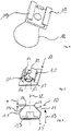
- FIGS. 1 and 3 show a system for detachably fastening a component 1 of an air conditioning and ventilation system.
- the system comprises a holding element 2 and a fastening element 3 which can be attached detachably thereto
- Figures 1 and 3 illustrated system according to the invention around a rail, for example, a ceiling construction.
- a recess 4 is provided in the holding element 2 and is arranged in a tongue-like partial area which is encompassed by two slots 5 on both sides.
- the fastening element 3 is designed as a screw. At one of the two ends of the fastener 3 is a not shown External thread 6 is provided to form a helical thread and at the other end a head region 8 covering an opening 7 of the component 1 to be fastened.
- the external thread 8 is designed as a metric thread.
- the component 1 can be a plate, for example, which is fastened to a holding element 2 from below.
- spacer webs 9 are also provided on the side of the component 1 facing the holding element 2 . In the fastened state, the spacer webs 9 bear against the holding element 2 with their respective upper end.
- the opening 7 is provided in the component 1 , through which the fastening element 3 is passed for fastening the component 1 .
- a counter-element 10 with an internal thread that interacts with the external thread 6 of the fastening element 3 is assigned to the holding element 2 .
- the counter-element 10 is designed as a separate component in the exemplary embodiments shown.
- the counter-element 10 has two spaced-apart portions 11 that form the internal thread and protrude in the form of webs, which are formed on a base plate 15 .
- Each partial area 11 has a contact area 12 at the end, which interacts with the external thread 6 of the fastening element 3 in the assembled state.
- the partial areas 11 are made of spring steel, so that each partial area 11 and thus also the relevant contact area 12 can be displaced outwards against a spring force. When swiveling outwards, the distance between the contact area 12 and the center line M increases.
- the fastening element 3 can easily be pressed into the internal thread of the counter-element 10 without a tool, viewed in the direction of insertion 13 . This makes assembly easier.
- the fastening means 3 can be unscrewed again counter to the insertion direction 13 in a conventional manner by means of a tool, for example a screwdriver.
- the contact areas 12 of the two sub-areas 11 are offset from one another by half the pitch a, as viewed in the direction of insertion 13 .
- the two contact areas 12 arranged opposite one another thus both engage in the thread turn of the external thread 6 .
- each sub-area 11 in front of the contact area 12, that is to say in the area 14, is beveled as seen in the direction of insertion 13.
- the contact area 12 refers to that part of each of the two sub-areas 11 which is in direct contact with the fastening means 3, ie engages in a thread of the external thread 6, for example.
- each partial area 11 is angled in such a way that, viewed in the direction of insertion 13, the distance from the center line M first increases and then decreases again toward the contact area 12.
- the partial areas 11 of the counter-element 10 are guided through the recess 4 of the holding element 2 from below.
- the recess 4 is designed in such a way that the base plate 15 rests on the edge region of the recess 4 from below, at least in certain areas, after the partial regions 11 have been passed through the recess 4 in the holding element 2 from below. After the later insertion of the fastening element 3, the partial areas 11 spread open as a result prevent the counter-element 10 from accidentally slipping out of the recess 4.
- the clamping force of the partial areas 11 can be influenced by varying the width of the recess 4 in the area on which the partial areas 11 rest will. If a component 1 with a higher weight is to be fastened, a somewhat smaller width of the recess 4 is selected. The partial areas 11 thus lie closer to the edge of the recess 4 or are already prestressed. As a result, a higher force has to be applied when pressing in the fastening means 3, since only a smaller length of each partial area 11 is available for outward displacement or a higher force has to be applied due to the pretension. As a result, in the mounted state, a higher clamping force is exerted by the partial areas 11 on the fastening element 3 . Thus, by selecting the appropriate size of the recess 4, one and the same counter-element 10 can be used for fastening components 1 of different weights.
- the base plate 15 has an opening 16, the partial areas 11 being formed around the opening 16 on the base plate 15.
- the edge of the opening 16 has a collar 17 pointing in the direction of the contact areas 12 in two opposite areas.
- the collars 17 facilitate the insertion of the fastener 3 from below into the internal thread of the counter-element 10.
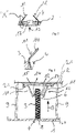
- the system according to the invention Figures 1 and 2 also has an insertion region 18 that converges in the shape of a funnel, viewed in the direction of insertion 13 and is designed as a separate component.
- the separate component can be fastened to the holding element 2 by means of a fixing device.
- the converging insertion area 18 has, in its area in contact with the holding element 2 , two slot-like holding arms 19 arranged at a distance from one another and pointing towards one another, which grip around the edge of the area of the holding element 2 forming the recess 4 .
- the two partial areas 11 of the counter-element 10 are first guided from below into the recess 4 of the holding element 2, which is open at the bottom and is designed as a rail.
- the converging insertion area 18 which is designed as a separate component, is then moved from below into the holding element 2, which is designed as a rail that opens downwards, in such a way that the slot-like holding arms 19 are pushed by lateral displacement onto the tongue-like partial area with the recess 4 be able.
- the funnel-shaped converging insertion area 18 allows a concealed, simple insertion of the fastening element 3 into the counter-element 10 since the fastening element 3 is guided through the converging insertion area 18 .
- the converging insertion area 18 has on its outside a holding device 20 for an additional element, such as a measuring nipple.
- the holding device 20 consists of two clamping arms between which, for example, a hose can be clamped.
- the holding element 2 has on its underside two spaced-apart slots 21 into which the base plate 15 is inserted with its edge region. No opening 16 is provided in the base plate 15 .
- the holding element 2 also has no recess 4 .
- the fastening element 3 is pressed in the same way into the counter-element 10 for assembly and can be unscrewed again.
Description
Die Erfindung betrifft ein System zur lösbaren Befestigung eines Bauteils einer klima- und raumlufttechnischen Anlage, wobei das System ein Halteelement sowie ein daran lösbar anbringbares Befestigungselement umfasst, wobei weiterhin das Bauteil mittels zumindest eines, durch eine Öffnung in dem zu befestigenden Bauteil führbares Befestigungselement anbringbar ist, wobei das Befestigungselement an einem Ende ein Außengewinde unter Bildung eines wendelförmig ausgebildeten Gewindegangs aufweist und am anderen Ende einen die Öffnung des Bauteils zumindest teilweise überdeckenden Kopfbereich umfasst, und wobei dem Halteelement ein mit dem Außengewinde des Befestigungselements zusammenwirkendes Gegenelement mit einem Innengewinde zugeordnet ist und wobei im montierten Zustand das mit dem Außengewinde versehene Ende des Befestigungselementes mit dem Innengewinde des Gegenelementes zusammenwirkend ausgebildet ist. Die Öffnung muss nicht zwingend von allen Seiten umschlossen sein. Es ist auch möglich, dass die Öffnung im Randbereich des Bauteils liegt und zum Rand hin offen sein kann.The invention relates to a system for the detachable fastening of a component of an air-conditioning and ventilation system, the system comprising a holding element and a fastening element that can be detachably attached thereto, the component also being attachable by means of at least one fastening element that can be guided through an opening in the component to be fastened , wherein the fastening element has an external thread at one end, forming a helical thread and at the other end comprises a head region which at least partially covers the opening of the component, and wherein the retaining element is assigned a counter-element which interacts with the external thread of the fastening element and has an internal thread and wherein in the mounted state, the end of the fastening element provided with the external thread is designed to interact with the internal thread of the counter-element. The opening does not necessarily have to be enclosed on all sides. It is also possible that the opening is in the edge area of the component and can be open towards the edge.
Bei dem Befestigungselement handelt es sich um eine Schraube, die vom Raum nach Anlegen des Bauteils in der gewünschten Position in das Gegenelement eingeschraubt wird. Nachteilig ist, dass das Eindrehen der Schraube bei der Montage, das mittels eines Werkzeuges erfolgt, recht zeitaufwändig ist, insbesondere wenn der Eindrehweg lang ist. Während dieser Zeit muss dasThe fastening element is a screw that is screwed into the counter-element from the room after the component has been placed in the desired position. The disadvantage is that screwing in the screw during assembly, which is done using a tool, is quite time-consuming, especially when the turning path is long. During this time it must
Bauteil mit der anderen Hand gehalten werden.component to be held with the other hand.
Aufgabe der Erfindung ist es, die vorgenannten Nachteile zu vermeiden und ein System anzugeben, das eine einfachere Montage des Bauteils ermöglicht.The object of the invention is to avoid the aforementioned disadvantages and to specify a system that enables simpler assembly of the component.
Diese Aufgabe wird dadurch gelöst, dass das Gegenelement zumindest zwei im Abstand zueinander angeordnete, das Innengewinde bildende, stegförmig vorspringende Teilbereiche aufweist, wobei jeder Teilbereich einen, vorzugsweise endseitigen, Kontaktbereich aufweist, der im montierten Zustand mit dem Befestigungselement zusammenwirkt, und wobei zumindest der Kontaktbereich wenigstens eines Teilbereichs gegen eine Federkraft nach außen unter Vergrößerung des Abstandes zu dem (den) weiteren Teilbereiche(n) verlagerbar ist, so dass das Befestigungselement in Einführrichtung gesehen ohne ein Werkzeug in das Innengewinde drückbar und entgegen die Einführrichtung mittels eines Werkzeuges herausdrehbar ist und dass das Gegenelement auf seiner den Teilbereichen gegenüberliegenden Seite einen in Einführrichtung gesehen trichterförmig zusammenlaufenden Einführbereich aufweist.This object is achieved in that the counter-element has at least two spaced-apart sub-areas that form the internal thread and protrude in the form of webs, each sub-area having a contact area, preferably at the end, which interacts with the fastening element in the assembled state, and wherein at least the contact area at least one partial area can be displaced outwards against a spring force, thereby increasing the distance to the other partial area(s), so that the fastening element, seen in the direction of insertion, can be pressed into the internal thread without a tool and can be unscrewed against the direction of insertion by means of a tool and that the counter-element has, on its side opposite the partial areas, an insertion area that converges in the shape of a funnel, viewed in the insertion direction.
Das Außengewinde stellt eine profilierte Einkerbung dar und verläuft fortlaufend nach Art einer Wendel um die Wandung des Befestigungselementes herum. Das Außengewinde weist insoweit eine Steigung auf. Bei dem Außengewinde kann es sich beispielsweise um ein Trapezgewinde oder ein Whitworth-Gewinde oder dergleichen handeln. Auch kann das Außengewinde als Linksgewinde ausgebildet sein. Bei dem Halteelement kann es sich beispielsweise um eine Schiene handeln, die Bestandteil einer Komponente der klimatechnischen Anlage ist oder bereits bauseitig in dem Raum, in dem die raumlufttechnische Anlage montiert ist, vorhanden ist. Das Bauteil kann beispielsweise eine frontseitige Platte eines Durchlasses darstellen.The external thread represents a profiled indentation and runs continuously around the wall of the fastening element in the manner of a helix. To this extent, the external thread has a slope. The external thread can be, for example, a trapezoidal thread or a Whitworth thread or the like. The external thread can also be designed as a left-hand thread. The retaining element can be a rail, for example, which is part of a component of the air-conditioning system or is already present on site in the room in which the air-conditioning system is installed. The component can represent, for example, a front plate of a passage.
Die federnde Ausgestaltung erlaubt ein einfaches Eindrücken des Befestigungselements in Einführrichtung gesehen in das Innengewinde des Gegenelementes. Hierfür ist kein Werkzeug erforderlich. Dies erleichtert und beschleunigt die Montage. Im montierten Zustand wirkt das mit dem Außengewinde versehene Ende des Befestigungselementes mit dem Innengewinde des Gegenelementes zusammen. Mittels eines Werkzeuges, beispielsweise eines Schraubendrehers, kann das Befestigungsmittel auf eine herkömmliche Weise wieder entgegen die Einführrichtung herausgedreht werden.The resilient configuration allows the fastening element to be easily pressed into the internal thread of the counter-element, as viewed in the direction of insertion. No tools are required for this. This facilitates and speeds up assembly. In the installed state, the end of the fastening element provided with the external thread interacts with the internal thread of the counter-element. By means of a tool, for example one Screwdriver, the fastener can be unscrewed in a conventional manner against the direction of insertion.
Zumindest ein Teilbereich kann wenigstens bereichsweise, vorzugsweise vollständig, aus Federstahl oder aus einem federnden Kunststoff bestehen. Selbstverständlich sind auch andere geeignete Materialien denkbar.At least one partial area can consist of spring steel or a resilient plastic, at least in some areas, preferably completely. Of course, other suitable materials are also conceivable.
Zumindest ein Gegenelement kann Teil des Halteelementes sein. Bei einer solchen Ausgestaltung sind die Teilbereiche direkt auf das Halteelement beispielsweise aufgeklebt oder aufgeschweißt.At least one counter element can be part of the holding element. In such an embodiment, the partial areas are, for example, glued or welded directly onto the holding element.
Alternativ kann zumindest ein Gegenelement als separates Bauteil ausgebildet sein, und die Teilbereiche können an einer Grundplatte angeformt sein.Alternatively, at least one counter-element can be designed as a separate component, and the partial areas can be formed on a base plate.
Die Grundplatte kann eine Öffnung aufweisen, und die Teilbereiche können um die Öffnung herum an der Grundplatte angeformt sein. Die Öffnung ermöglicht, dass das Befestigungselement durch das Gegenelement hindurchragen kann.The base plate may have an opening and the portions may be molded to the base plate around the opening. The opening allows the fastening element to protrude through the counter-element.
Der Rand der Öffnung kann zumindest bereichsweise, vorzugsweise vollständig, einen in Richtung der Kontaktbereiche weisenden Kragen aufweisen. Dieser Kragen dient zur Führung des Befestigungselementes beim Einführen in das Innengewinde.The edge of the opening can have a collar pointing in the direction of the contact areas, at least in regions, preferably completely. This collar is used to guide the fastener when inserting it into the internal thread.
Wenigstens ein Teilbereich kann vor dem Kontaktbereich in Einführrichtung gesehen abgeschrägt ausgebildet sein. Dies erleichtert das Einführen des Befestigungselementes in das Innengewinde.At least one partial area can be beveled in front of the contact area as seen in the direction of insertion. This facilitates the insertion of the fastener into the internal thread.
Zumindest ein Teilbereich kann derart abgewinkelt ausgebildet sein, dass sich in Einführrichtung gesehen der Abstand zu der Mittellinie M zunächst vergrößert und dann zum Kontaktbereich hin verringert.At least one partial area can be angled in such a way that, seen in the direction of insertion, the distance from the center line M first increases and then decreases towards the contact area.
Das Halteelement kann eine Ausnehmung aufweisen, die derart ausgestaltet ist, dass die Grundplatte nach dem Durchführen der Teilbereiche durch die Ausnehmung zumindest bereichsweise auf dem Randbereich der Ausnehmung aufliegt. Sofern die Teilbereiche die vorbeschriebene abgewinkelte Ausgestaltung aufweisen, kann durch die Veränderung der Breite der Ausnehmung in dem Bereich, an dem die Teilbereiche anliegen, die Klemmkraft der Teilbereiche beeinflusst werden. Sofern ein Bauteil mit einem höheren Gewicht befestigt werden soll, wird eine etwas geringere Breite der Ausnehmung gewählt. Damit liegen die Teilbereiche, die beispielsweise aus einem Federstahl bestehen, enger oder bereits vorgespannt an dem Rand der Ausnehmung an. Infolgedessen muss eine höhere Kraft beim Eindrücken des Befestigungsmittels aufgebracht werden, da nur eine geringere Länge jedes Teilbereiches für eine nach außen Verlagerung zur Verfügung steht oder infolge der Vorspannung eine höhere Kraft aufgebracht werden muss. Infolgedessen wird im montierten Zustand eine höhere Klemmkraft von den Teilbereichen auf das Befestigungselement ausgeübt. Damit kann ein und dasselbe Gegenelement zur Befestigung von Bauteilen unterschiedlichen Gewichts verwendet werden.The holding element can have a recess which is designed such that the base plate after the implementation of the sub-regions through the Recess at least partially rests on the edge region of the recess. If the sub-areas have the angled configuration described above, the clamping force of the sub-areas can be influenced by changing the width of the recess in the area on which the sub-areas rest. If a component with a higher weight is to be fastened, a slightly smaller width of the recess is selected. The sub-areas, which are made of spring steel, for example, lie closer to the edge of the recess or are already prestressed. As a result, a higher force has to be applied when pressing in the fastening means, since only a smaller length of each partial area is available for outward displacement, or a higher force has to be applied due to the pretension. As a result, in the mounted state, a higher clamping force is exerted by the partial areas on the fastening element. This means that one and the same counter-element can be used to attach components of different weights.
Alternativ kann das Halteelement eine Ausnehmung sowie zwei auf gegenüberliegenden Seiten der Ausnehmung angeordnete Schlitze aufweisen, in die die Grundplatte mit ihrem Randbereich einführbar ist.Alternatively, the holding element can have a recess and two slots arranged on opposite sides of the recess, into which the base plate can be inserted with its edge area.
Es ist auch möglich, dass das Halteelement zwei im Abstand zueinander angeordnete Schlitze aufweist, in die die Grundplatte mit ihrem Randbereich einführbar ist.It is also possible for the holding element to have two slots which are arranged at a distance from one another and into which the edge region of the base plate can be inserted.
Die Kontaktbereiche der Teilbereiche können in Einführrichtung gesehen entsprechend der Steigung derart versetzt zueinander angeordnet sein, so dass jeder Kontaktbereich in den Gewindegang eingreift. Durch das Eingreifen jedes Kontaktbereichs ist eine besonders sichere Befestigung gewährleistet.Seen in the direction of insertion, the contact areas of the sub-areas can be arranged offset from one another in accordance with the slope in such a way that each contact area engages in the thread turn. The engagement of each contact area ensures a particularly secure attachment.
Es bietet sich an, wenn zwei gegenüberliegende Teilbereiche vorgesehen sind, wobei die Kontaktbereiche der beiden Teilbereiche in Einführrichtung gesehen um die halbe Steigung versetzt zueinander angeordnet sind. In diesem Fall sind die Kontaktbereiche gegenüberliegend angeordnet. Beide Kontaktbereiche greifen gleichzeitig in den Gewindegang ein.It makes sense to provide two opposite sub-areas, with the contact areas of the two sub-areas being offset from one another by half the pitch, as viewed in the direction of insertion. In In this case, the contact areas are arranged opposite one another. Both contact areas engage in the thread at the same time.
Das Befestigungselement kann als Außengewinde ein metrisches Gewinde oder ein metrisches Feingewinde aufweisen.The fastening element can have a metric thread or a fine metric thread as the external thread.
Das Befestigungselement kann als Schraube ausgebildet sein.The fastening element can be designed as a screw.
Das Gegenelement weist auf seiner den Teilbereichen gegenüberliegenden Seite einen in Einführrichtung gesehen trichterförmig zusammenlaufenden Einführbereich auf. Beim Einführen des Befestigungselementes bei der Montage wird das eingeführte Ende des Befestigungselementes durch den zusammenlaufenden Einführbereich geführt.On its side opposite the partial areas, the counter-element has an insertion area that converges in the shape of a funnel, viewed in the insertion direction. When inserting the fastener during assembly, the inserted end of the fastener is passed through the converging insertion area.
Der zusammenlaufende Einführbereich kann als separates Bauteil ausgebildet sein und mittels einer Fixiereinrichtung an dem Gegenelement bzw. an dem Halteelement befestigbar sein.The converging insertion area can be designed as a separate component and can be fastened to the counter-element or to the holding element by means of a fixing device.
Dabei kann der zusammenlaufende Einführbereich in seinem mit dem Halteelement in Kontakt befindlichen Bereich zwei im Abstand zueinander angeordnete und aufeinander zuweisende, insbesondere schlitzartige ausgebildete, Haltearme aufweisen, die den die Ausnehmung bildenden Bereich des Halteelementes randseitig umgreifen.The converging insertion area in its area in contact with the holding element can have two spaced-apart and facing one another, in particular slit-like, holding arms which surround the edge of the area of the holding element forming the recess.
Der zusammenlaufende Einführbereich kann, vorzugsweise an seiner Außenseite, zumindest eine Halteeinrichtung für ein Zusatzelement, wie beispielsweise einen Messnippel, aufweisen.The converging insertion area can have at least one holding device for an additional element, such as a measuring nipple, preferably on its outside.
Im Folgenden werden in den Zeichnungen dargestellte Ausführungsbeispiele der Erfindung erläutert. Es zeigen:
- Fig. 1
- das erfindungsgemäße System ohne ein Bauteil,
- Fig. 2
- einen Schnitt durch ein Gegenelement und einem als separates Bauteil ausgebildeten zusammenlaufenden Einführbereich mit einem darin eingeführten Befestigungselement,
- Fig. 3
- eine schräge Draufsicht auf ein Halteelement,
- Fig. 4
- eine schräge Draufsicht auf ein als separates Bauteil ausgebildeter zusammenlaufender Einführbereich,
- Fig. 5
- eine schräge Draufsicht auf ein Gegenelement,
- Fig. 6
- einen Schnitt durch den Gegenstand nach
Fig. 5 , - Fig. 7
- ein Schnitt durch ein Halteelement mit einer Ausnehmung und einem darin eingesetzten Gegenelement,
- Fig. 8
- das Detail "X" aus
Fig. 7 und - Fig. 9
- eine Seitenansicht auf ein anderes Ausführungsbeispiel.
- 1
- the system according to the invention without a component,
- 2
- a section through a counter element and a converging insertion area designed as a separate component with a fastening element inserted therein,
- 3
- an oblique top view of a holding element,
- 4
- an oblique plan view of a converging insertion area designed as a separate component,
- figure 5
- an oblique top view of a counter-element,
- 6
- trace a section through the object
figure 5 , - 7
- a section through a holding element with a recess and a counter-element inserted therein,
- 8
- the detail "X".
Figure 7 and - 9
- a side view of another embodiment.
In allen Figuren werden für gleiche bzw. gleichartige Bauteile übereinstimmende Bezugszeichen verwendet.The same reference numbers are used in all figures for the same or similar components.
Die Figuren zeigen ein System zur lösbaren Befestigung eines Bauteils 1 einer klima- und raumlufttechnischen Anlage. Das System umfasst neben dem Bauteil 1 ein Halteelement 2 und ein daran lösbar anbringbares Befestigungselement 3. Bei dem Halteelement 2 handelt es sich in dem in den
Das Befestigungselement 3 ist als Schraube ausgebildet. An dem einen der beiden Enden des Befestigungselements 3 ist ein nicht näher dargestelltes Außengewinde 6 unter Bildung eines wendelförmig ausgebildeten Gewindegangs und am anderen Ende ein eine Öffnung 7 des zu befestigenden Bauteils 1 überdeckender Kopfbereich 8 vorgesehen. Das Außengewinde 8 ist als metrisches Gewinde ausgebildet.The
Bei dem Bauteil 1 kann es sich beispielsweise um eine Platte handeln, die von unten an einem Haltelement 2 befestigt ist. Bei dem in
Dem Halteelement 2 ist ein mit dem Außengewinde 6 des Befestigungselements 3 zusammenwirkendes Gegenelement 10 mit einem Innengewinde zugeordnet. Das Gegenelement 10 ist in den dargestellten Ausführungsbeispielen als separates Bauteil ausgebildet. Das Gegenelement 10 weist zwei im Abstand zueinander angeordnete, das Innengewinde bildende, stegförmig vorspringende Teilbereiche 11 auf, die an einer Grundplatte 15 angeformt sind. Jeder Teilbereich 11 weist einen endseitigen Kontaktbereich 12 auf, der im montierten Zustand mit dem Außengewinde 6 des Befestigungselements 3 zusammenwirkt.A counter-element 10 with an internal thread that interacts with the
Die Teilbereiche 11 bestehen aus einem Federstahl, so dass damit jeder Teilbereich 11 und damit auch der betreffende Kontaktbereich 12 gegen eine Federkraft nach außen verlagerbar ist. Beim nach außen Schwenken vergrößert sich der Abstand zwischen dem Kontaktbereich 12 und der Mittelinie M.The
Durch diese federnde Ausgestaltung kann das Befestigungselement 3 einfach in Einführrichtung 13 gesehen ohne ein Werkzeug in das Innengewinde des Gegenelementes 10 gedrückt werden. Dies erleichtert die Montage. Im montierten Zustand wirkt das mit dem Außengewinde 6 versehene Ende des Befestigungselementes 3 mit dem Innengewinde des Gegenelementes 10 zusammen. Mittels eines Werkzeuges, beispielsweise eines Schraubendrehers, kann das Befestigungsmittel 3 auf eine herkömmliche Weise wieder entgegen die Einführrichtung 13 herausgedreht werden.As a result of this resilient design, the
Wie
Wie die
Bei den Ausgestaltungen nach den
Bei dem Ausführungsbeispiel nach den
Durch die Variation der Breite der Ausnehmung 4 in dem Bereich, an dem die Teilbereiche 11 anliegen, kann die Klemmkraft der Teilbereiche 11 beeinflusst werden. Sofern ein Bauteil 1 mit einem höheren Gewicht befestigt werden soll, wird eine etwas geringere Breite der Ausnehmung 4 gewählt. Damit liegen die Teilbereiche 11 enger oder bereits vorgespannt an dem Rand der Ausnehmung 4 an. Infolgedessen muss eine höhere Kraft beim Eindrücken des Befestigungsmittels 3 aufgebracht werden, da nur eine geringere Länge jedes Teilbereiches 11 für eine nach außen Verlagerung zur Verfügung steht oder infolge der Vorspannung eine höhere Kraft aufgebracht werden muss. Infolgedessen wird im montierten Zustand eine höhere Klemmkraft von den Teilbereichen 11 auf das Befestigungselement 3 ausgeübt. Damit kann durch Auswahl der passenden Größe der Ausnehmung 4 ein und dasselbe Gegenelement 10 zur Befestigung von Bauteilen 1 unterschiedlichen Gewichts verwendet werden.The clamping force of the
Bei dem erfindungsgemäßen System nach den
Das erfindungsgemäße System nach den
Der zusammenlaufende Einführbereich 18 weist an seiner Außenseite eine Halteeinrichtung 20 für ein Zusatzelement, wie beispielsweise einen Messnippel, auf. Die Halteeinrichtung 20 besteht aus zwei Klemmarmen, zwischen denen beispielsweise ein Schlauch einklemmbar ist.The converging
In
Claims (18)
- System for reversibly attaching an element (1) of an air-conditioning and ventilation assembly, wherein the system comprises a retaining element (2), and a securing element (3) which can be reversibly attached to it, wherein the element (1) can be further attached by means of at least one securing element (3) which can be guided through an opening (7) in the element (1) which is to be secured, wherein the securing element (3) comprises at one end an outer thread (6), with the formation of a thread configured as a spiral, and, at the other end, comprises a head region (8) which at least partially covers the opening (7) of the element (1), and wherein a counter element (10) with an inner thread is assigned to the retaining element (2), which interacts with the outer thread (6) of the securing element (3), and wherein, in the installed state, the end of the securing element (3) provided with the outer thread (6) is configured such as to interact with the inner thread of the counter element (10), the counter element (10) comprises at least two part regions (11), arranged at a distance interval from one another and projecting in the form of a web, forming the inner thread, wherein each part region (11) comprises s contact region (12), preferably on the end side, which in the installed state interacts with the securing element (3), and wherein at least the contact region (12) of at least one part region (11) can be displaced outwards against a spring force, such that the securing element (3), seen in the introduction direction (13), can be pressed into the inner thread without a tool, and can be rotated outwards, against the introduction direction (13) by means of a tool, characterised in that the counter element (10) comprises, on its side opposite the part regions (11) and seen in the introduction direction (13), an introduction region (18) which converges in the form of a funnel. 33
- System according to the preceding claim, characterised in that at least one part region (11) consists at least in some areas, and preferably entirely, of spring steel or of a spring plastic.
- System according to any one of the preceding claims, characterised in that at least one counter element (10) is a part of the retaining element (2).
- System according to any one of the preceding claims, characterised in that at least one counter element (10) is formed as a separate element, and that the part regions (11) are formed on a base plate (15).
- System according to any one of the preceding claims, characterised in that the base plate (15) has an opening (16), and the part regions (11) around the opening (16) are formed on the base plate (15).
- System according to any one of the preceding claims, characterised in that the edge of the opening (16) comprises, at least in some regions and preferably completely, a collar (17) pointing in the direction of the contact regions (12).
- System according to any one of the preceding claims, characterised in that at least one part region (11) before the contact region (12) is configured as slanted, seen in the introduction direction (13).
- System according to any one of the preceding claims, characterised in that at least one part region (11) is configured as angled in such a way that, seen in the introduction direction (13), the distance interval to the mid-line M is initially enlarged, and then reduces in size towards the contact region (12).
- System according to any one of claims 4 to 8, characterised in that the retaining element (2) exhibits a cut-out opening (4), which is configured in such a way that the base plate (15), after the part regions (11) have been guided through the cut-out opening (4), comes to lie in contact at least in some parts, on the edge region of the cut-out opening (4).
- System according to any one of claims 4 to 8, characterised in that the retaining element (2) exhibits a cut-out opening (4), as well as two slots (21), arranged on opposing sides of the cut-out opening (4), into which the base plate (15) can be introduced with its edge region.
- System according to any one of claims 4 to 8, characterised in that the retaining element (2) comprises two slots (21), arranged at a distance interval from each other, into which the base plate (15) can be introduced with its edge region,
- System according to any one of the preceding claims, characterised in that the contact regions (12) of the part regions (11), seen in the introduction direction (13), are arranged offset to one another, in accordance with the thread pitch, in such a way that each contact region (12) engages into the thread path.
- System according to any one of the preceding claims, characterised in that two opposing part regions (11) are provided, wherein the contact regions (12) of the two part regions (11), seen in the introduction direction (13), are arranged offset to one another by half of the thread pitch.
- System according to any one of the preceding claims, characterised in that the securing element (3), as an outer thread (6), comprises a metric thread or a metric fine thread.
- System according to any one of the preceding claims, characterised in that the securing element (3) is configured as a screw.
- System according to any one of the preceding claims, characterised in that the converging introduction region (18) is formed as a separate element, and can be secured by means of a fixing device to the counter element (10) or to the retaining element (2) respectively.
- System according to any one of the preceding claims, inasmuch as these relate back to claim 9, characterised in that the converging introduction region (18), in its region which is in contact with the retaining element (2), comprises two holding arms (19), arranged at a distance interval from each another and facing towards each other, in particular configured in the form of slots, which engage around the region of the retaining element (2) forming the cut-out opening (4).
- System according to any one of the preceding claims, characterised in that the converging introduction region (18) comprises, preferably on its outer side, at least one retaining device (20) for an additional element, such as, for example, a measurement nipple.
Applications Claiming Priority (1)
| Application Number | Priority Date | Filing Date | Title |
|---|---|---|---|
| DE202017101384.7U DE202017101384U1 (en) | 2017-03-10 | 2017-03-10 | System for releasably attaching a component of a climate and air conditioning system |
Publications (2)
| Publication Number | Publication Date |
|---|---|
| EP3372916A1 EP3372916A1 (en) | 2018-09-12 |
| EP3372916B1 true EP3372916B1 (en) | 2022-11-09 |
Family
ID=59295766
Family Applications (1)
| Application Number | Title | Priority Date | Filing Date |
|---|---|---|---|
| EP18160675.7A Active EP3372916B1 (en) | 2017-03-10 | 2018-03-08 | System for reversibly attaching an element of air conditioning and ventilation assembly |
Country Status (3)
| Country | Link |
|---|---|
| EP (1) | EP3372916B1 (en) |
| DE (1) | DE202017101384U1 (en) |
| ES (1) | ES2935182T3 (en) |
Families Citing this family (1)
| Publication number | Priority date | Publication date | Assignee | Title |
|---|---|---|---|---|
| DE202018102853U1 (en) * | 2018-05-22 | 2019-08-27 | Trox Gmbh | Passage of an air-conditioning system for the ventilation of rooms |
Family Cites Families (5)
| Publication number | Priority date | Publication date | Assignee | Title |
|---|---|---|---|---|
| US4508477A (en) * | 1982-09-30 | 1985-04-02 | Eaton Corporation | Fastening device |
| DE102006001741A1 (en) * | 2006-01-13 | 2007-08-02 | A. Raymond Et Cie | Captive threaded nut for latching into hole in plate is formed with self retaining spring arms |
| JP4738323B2 (en) * | 2006-12-06 | 2011-08-03 | 株式会社パイオラックス | Fastener |
| US10197088B2 (en) * | 2011-11-10 | 2019-02-05 | Oldcastle Precast, Inc. | Tamper resistant closure mechanism for a utility vault |
| JP2017187046A (en) * | 2013-10-03 | 2017-10-12 | ポップリベット・ファスナー株式会社 | Stud engagement unit |
-
2017
- 2017-03-10 DE DE202017101384.7U patent/DE202017101384U1/en active Active
-
2018
- 2018-03-08 ES ES18160675T patent/ES2935182T3/en active Active
- 2018-03-08 EP EP18160675.7A patent/EP3372916B1/en active Active
Also Published As
| Publication number | Publication date |
|---|---|
| DE202017101384U1 (en) | 2017-06-21 |
| EP3372916A1 (en) | 2018-09-12 |
| ES2935182T3 (en) | 2023-03-02 |
Similar Documents
| Publication | Publication Date | Title |
|---|---|---|
| EP2136969B1 (en) | Device for processing a belt strap for storing screws | |
| EP1447576B1 (en) | Plastic nut for a construction unit exhibiting a break-through | |
| EP2376791A1 (en) | Distance device and fastening system having distance device | |
| EP3586018B1 (en) | Fastening device and fastening assembly | |
| DE102012221228A1 (en) | Device for compensating tolerances between two screwed components, has spacer ring that acts in axial direction and is moved to component against restoring force of fastener fixedly connected to base element | |
| EP2110567A2 (en) | Device for securing a threaded connection | |
| EP3643847A1 (en) | Fastening system and rail for a fastening system | |
| DE4309330C2 (en) | Spacer for pipe clamps | |
| EP1775482B1 (en) | Quick-fastening element | |
| EP3372916B1 (en) | System for reversibly attaching an element of air conditioning and ventilation assembly | |
| EP3326249B1 (en) | Arrangement comprising a roof system and a fastening system for the fastening of the roof system on the roof of an electrical cabinet | |
| EP3586013B1 (en) | Fastening assembly | |
| DE102007042034A1 (en) | Fixing system for fastening components, in particular for motor vehicles | |
| DE60314807T2 (en) | sealing device | |
| DE202006013530U1 (en) | Bolt with retaining washer | |
| EP3443233B1 (en) | Clip for fastening a first element to a second element | |
| DE2531368B2 (en) | Fastening device for handles, armrests or the like. on the inside wall of the vehicle body | |
| DE19734601A1 (en) | Perforated disc | |
| EP0609973B1 (en) | Device for fixing of angled coverbrackets | |
| DE102008025788A1 (en) | Fastening clamp for use as quick fastener, has base body exhibiting pre-loading unit for exertion of axial pre-load on fastening part, and clamp unit exhibiting spring plate with spring element designed as closed ring | |
| DE2946993C2 (en) | ||
| DE102018107083A1 (en) | Fastening device and method for fastening an attachment to a support member, component system and motor vehicle | |
| DE19849109B4 (en) | connecting element | |
| DE19621665C2 (en) | Device for attaching a picture tube | |
| EP3504385B1 (en) | Awning fastening system |
Legal Events
| Date | Code | Title | Description |
|---|---|---|---|
| PUAI | Public reference made under article 153(3) epc to a published international application that has entered the european phase |
Free format text: ORIGINAL CODE: 0009012 |
|
| STAA | Information on the status of an ep patent application or granted ep patent |
Free format text: STATUS: THE APPLICATION HAS BEEN PUBLISHED |
|
| AK | Designated contracting states |
Kind code of ref document: A1 Designated state(s): AL AT BE BG CH CY CZ DE DK EE ES FI FR GB GR HR HU IE IS IT LI LT LU LV MC MK MT NL NO PL PT RO RS SE SI SK SM TR |
|
| AX | Request for extension of the european patent |
Extension state: BA ME |
|
| STAA | Information on the status of an ep patent application or granted ep patent |
Free format text: STATUS: REQUEST FOR EXAMINATION WAS MADE |
|
| 17P | Request for examination filed |
Effective date: 20190307 |
|
| RBV | Designated contracting states (corrected) |
Designated state(s): AL AT BE BG CH CY CZ DE DK EE ES FI FR GB GR HR HU IE IS IT LI LT LU LV MC MK MT NL NO PL PT RO RS SE SI SK SM TR |
|
| STAA | Information on the status of an ep patent application or granted ep patent |
Free format text: STATUS: EXAMINATION IS IN PROGRESS |
|
| 17Q | First examination report despatched |
Effective date: 20200731 |
|
| STAA | Information on the status of an ep patent application or granted ep patent |
Free format text: STATUS: EXAMINATION IS IN PROGRESS |
|
| GRAP | Despatch of communication of intention to grant a patent |
Free format text: ORIGINAL CODE: EPIDOSNIGR1 |
|
| STAA | Information on the status of an ep patent application or granted ep patent |
Free format text: STATUS: GRANT OF PATENT IS INTENDED |
|
| INTG | Intention to grant announced |
Effective date: 20220601 |
|
| GRAS | Grant fee paid |
Free format text: ORIGINAL CODE: EPIDOSNIGR3 |
|
| GRAA | (expected) grant |
Free format text: ORIGINAL CODE: 0009210 |
|
| STAA | Information on the status of an ep patent application or granted ep patent |
Free format text: STATUS: THE PATENT HAS BEEN GRANTED |
|
| AK | Designated contracting states |
Kind code of ref document: B1 Designated state(s): AL AT BE BG CH CY CZ DE DK EE ES FI FR GB GR HR HU IE IS IT LI LT LU LV MC MK MT NL NO PL PT RO RS SE SI SK SM TR |
|
| REG | Reference to a national code |
Ref country code: GB Ref legal event code: FG4D Free format text: NOT ENGLISH |
|
| REG | Reference to a national code |
Ref country code: CH Ref legal event code: EP Ref country code: AT Ref legal event code: REF Ref document number: 1530613 Country of ref document: AT Kind code of ref document: T Effective date: 20221115 |
|
| REG | Reference to a national code |
Ref country code: DE Ref legal event code: R096 Ref document number: 502018010986 Country of ref document: DE |
|
| REG | Reference to a national code |
Ref country code: IE Ref legal event code: FG4D Free format text: LANGUAGE OF EP DOCUMENT: GERMAN |
|
| REG | Reference to a national code |
Ref country code: NL Ref legal event code: FP |
|
| REG | Reference to a national code |
Ref country code: LT Ref legal event code: MG9D |
|
| REG | Reference to a national code |
Ref country code: ES Ref legal event code: FG2A Ref document number: 2935182 Country of ref document: ES Kind code of ref document: T3 Effective date: 20230302 |
|
| PG25 | Lapsed in a contracting state [announced via postgrant information from national office to epo] |
Ref country code: SE Free format text: LAPSE BECAUSE OF FAILURE TO SUBMIT A TRANSLATION OF THE DESCRIPTION OR TO PAY THE FEE WITHIN THE PRESCRIBED TIME-LIMIT Effective date: 20221109 Ref country code: PT Free format text: LAPSE BECAUSE OF FAILURE TO SUBMIT A TRANSLATION OF THE DESCRIPTION OR TO PAY THE FEE WITHIN THE PRESCRIBED TIME-LIMIT Effective date: 20230309 Ref country code: NO Free format text: LAPSE BECAUSE OF FAILURE TO SUBMIT A TRANSLATION OF THE DESCRIPTION OR TO PAY THE FEE WITHIN THE PRESCRIBED TIME-LIMIT Effective date: 20230209 Ref country code: LT Free format text: LAPSE BECAUSE OF FAILURE TO SUBMIT A TRANSLATION OF THE DESCRIPTION OR TO PAY THE FEE WITHIN THE PRESCRIBED TIME-LIMIT Effective date: 20221109 Ref country code: FI Free format text: LAPSE BECAUSE OF FAILURE TO SUBMIT A TRANSLATION OF THE DESCRIPTION OR TO PAY THE FEE WITHIN THE PRESCRIBED TIME-LIMIT Effective date: 20221109 |
|
| PGFP | Annual fee paid to national office [announced via postgrant information from national office to epo] |
Ref country code: FR Payment date: 20230320 Year of fee payment: 6 Ref country code: AT Payment date: 20230317 Year of fee payment: 6 |
|
| PG25 | Lapsed in a contracting state [announced via postgrant information from national office to epo] |
Ref country code: RS Free format text: LAPSE BECAUSE OF FAILURE TO SUBMIT A TRANSLATION OF THE DESCRIPTION OR TO PAY THE FEE WITHIN THE PRESCRIBED TIME-LIMIT Effective date: 20221109 Ref country code: PL Free format text: LAPSE BECAUSE OF FAILURE TO SUBMIT A TRANSLATION OF THE DESCRIPTION OR TO PAY THE FEE WITHIN THE PRESCRIBED TIME-LIMIT Effective date: 20221109 Ref country code: LV Free format text: LAPSE BECAUSE OF FAILURE TO SUBMIT A TRANSLATION OF THE DESCRIPTION OR TO PAY THE FEE WITHIN THE PRESCRIBED TIME-LIMIT Effective date: 20221109 Ref country code: IS Free format text: LAPSE BECAUSE OF FAILURE TO SUBMIT A TRANSLATION OF THE DESCRIPTION OR TO PAY THE FEE WITHIN THE PRESCRIBED TIME-LIMIT Effective date: 20230309 Ref country code: HR Free format text: LAPSE BECAUSE OF FAILURE TO SUBMIT A TRANSLATION OF THE DESCRIPTION OR TO PAY THE FEE WITHIN THE PRESCRIBED TIME-LIMIT Effective date: 20221109 Ref country code: GR Free format text: LAPSE BECAUSE OF FAILURE TO SUBMIT A TRANSLATION OF THE DESCRIPTION OR TO PAY THE FEE WITHIN THE PRESCRIBED TIME-LIMIT Effective date: 20230210 |
|
| PGFP | Annual fee paid to national office [announced via postgrant information from national office to epo] |
Ref country code: GB Payment date: 20230323 Year of fee payment: 6 Ref country code: DE Payment date: 20230310 Year of fee payment: 6 |
|
| P01 | Opt-out of the competence of the unified patent court (upc) registered |
Effective date: 20230517 |
|
| PGFP | Annual fee paid to national office [announced via postgrant information from national office to epo] |
Ref country code: NL Payment date: 20230322 Year of fee payment: 6 |
|
| PG25 | Lapsed in a contracting state [announced via postgrant information from national office to epo] |
Ref country code: SM Free format text: LAPSE BECAUSE OF FAILURE TO SUBMIT A TRANSLATION OF THE DESCRIPTION OR TO PAY THE FEE WITHIN THE PRESCRIBED TIME-LIMIT Effective date: 20221109 Ref country code: RO Free format text: LAPSE BECAUSE OF FAILURE TO SUBMIT A TRANSLATION OF THE DESCRIPTION OR TO PAY THE FEE WITHIN THE PRESCRIBED TIME-LIMIT Effective date: 20221109 Ref country code: EE Free format text: LAPSE BECAUSE OF FAILURE TO SUBMIT A TRANSLATION OF THE DESCRIPTION OR TO PAY THE FEE WITHIN THE PRESCRIBED TIME-LIMIT Effective date: 20221109 Ref country code: DK Free format text: LAPSE BECAUSE OF FAILURE TO SUBMIT A TRANSLATION OF THE DESCRIPTION OR TO PAY THE FEE WITHIN THE PRESCRIBED TIME-LIMIT Effective date: 20221109 Ref country code: CZ Free format text: LAPSE BECAUSE OF FAILURE TO SUBMIT A TRANSLATION OF THE DESCRIPTION OR TO PAY THE FEE WITHIN THE PRESCRIBED TIME-LIMIT Effective date: 20221109 |
|
| PGFP | Annual fee paid to national office [announced via postgrant information from national office to epo] |
Ref country code: IT Payment date: 20230331 Year of fee payment: 6 Ref country code: ES Payment date: 20230414 Year of fee payment: 6 Ref country code: CH Payment date: 20230402 Year of fee payment: 6 |
|
| REG | Reference to a national code |
Ref country code: DE Ref legal event code: R097 Ref document number: 502018010986 Country of ref document: DE |
|
| PG25 | Lapsed in a contracting state [announced via postgrant information from national office to epo] |
Ref country code: SK Free format text: LAPSE BECAUSE OF FAILURE TO SUBMIT A TRANSLATION OF THE DESCRIPTION OR TO PAY THE FEE WITHIN THE PRESCRIBED TIME-LIMIT Effective date: 20221109 Ref country code: AL Free format text: LAPSE BECAUSE OF FAILURE TO SUBMIT A TRANSLATION OF THE DESCRIPTION OR TO PAY THE FEE WITHIN THE PRESCRIBED TIME-LIMIT Effective date: 20221109 |
|
| PLBE | No opposition filed within time limit |
Free format text: ORIGINAL CODE: 0009261 |
|
| STAA | Information on the status of an ep patent application or granted ep patent |
Free format text: STATUS: NO OPPOSITION FILED WITHIN TIME LIMIT |
|
| 26N | No opposition filed |
Effective date: 20230810 |
|
| PG25 | Lapsed in a contracting state [announced via postgrant information from national office to epo] |
Ref country code: MC Free format text: LAPSE BECAUSE OF FAILURE TO SUBMIT A TRANSLATION OF THE DESCRIPTION OR TO PAY THE FEE WITHIN THE PRESCRIBED TIME-LIMIT Effective date: 20221109 |
|
| PG25 | Lapsed in a contracting state [announced via postgrant information from national office to epo] |
Ref country code: SI Free format text: LAPSE BECAUSE OF FAILURE TO SUBMIT A TRANSLATION OF THE DESCRIPTION OR TO PAY THE FEE WITHIN THE PRESCRIBED TIME-LIMIT Effective date: 20221109 |
|
| REG | Reference to a national code |
Ref country code: BE Ref legal event code: MM Effective date: 20230331 |
|
| PG25 | Lapsed in a contracting state [announced via postgrant information from national office to epo] |
Ref country code: LU Free format text: LAPSE BECAUSE OF NON-PAYMENT OF DUE FEES Effective date: 20230308 |
|
| REG | Reference to a national code |
Ref country code: IE Ref legal event code: MM4A |
|
| PG25 | Lapsed in a contracting state [announced via postgrant information from national office to epo] |
Ref country code: IE Free format text: LAPSE BECAUSE OF NON-PAYMENT OF DUE FEES Effective date: 20230308 |
|
| PG25 | Lapsed in a contracting state [announced via postgrant information from national office to epo] |
Ref country code: BE Free format text: LAPSE BECAUSE OF NON-PAYMENT OF DUE FEES Effective date: 20230331 |
|
| PGFP | Annual fee paid to national office [announced via postgrant information from national office to epo] |
Ref country code: NL Payment date: 20240320 Year of fee payment: 7 |
|
| PGFP | Annual fee paid to national office [announced via postgrant information from national office to epo] |
Ref country code: AT Payment date: 20240318 Year of fee payment: 7 |