EP3372916B1 - Système de fixation amovible d'un composant d'une installation de climatisation et d'aéraulique - Google Patents
Système de fixation amovible d'un composant d'une installation de climatisation et d'aéraulique Download PDFInfo
- Publication number
- EP3372916B1 EP3372916B1 EP18160675.7A EP18160675A EP3372916B1 EP 3372916 B1 EP3372916 B1 EP 3372916B1 EP 18160675 A EP18160675 A EP 18160675A EP 3372916 B1 EP3372916 B1 EP 3372916B1
- Authority
- EP
- European Patent Office
- Prior art keywords
- region
- thread
- regions
- contact
- counter
- Prior art date
- Legal status (The legal status is an assumption and is not a legal conclusion. Google has not performed a legal analysis and makes no representation as to the accuracy of the status listed.)
- Active
Links
- 238000004378 air conditioning Methods 0.000 title claims description 6
- 238000009423 ventilation Methods 0.000 title claims description 4
- 229910000639 Spring steel Inorganic materials 0.000 claims description 4
- 210000002445 nipple Anatomy 0.000 claims description 3
- 230000015572 biosynthetic process Effects 0.000 claims 1
- 238000005259 measurement Methods 0.000 claims 1
- 238000003780 insertion Methods 0.000 description 34
- 230000037431 insertion Effects 0.000 description 34
- 238000006073 displacement reaction Methods 0.000 description 3
- 125000006850 spacer group Chemical group 0.000 description 3
- 230000007423 decrease Effects 0.000 description 2
- 238000010276 construction Methods 0.000 description 1
- 230000005484 gravity Effects 0.000 description 1
- 238000007373 indentation Methods 0.000 description 1
- 239000000463 material Substances 0.000 description 1
Images

Classifications
-
- F—MECHANICAL ENGINEERING; LIGHTING; HEATING; WEAPONS; BLASTING
- F24—HEATING; RANGES; VENTILATING
- F24F—AIR-CONDITIONING; AIR-HUMIDIFICATION; VENTILATION; USE OF AIR CURRENTS FOR SCREENING
- F24F13/00—Details common to, or for air-conditioning, air-humidification, ventilation or use of air currents for screening
- F24F13/32—Supports for air-conditioning, air-humidification or ventilation units
-
- F—MECHANICAL ENGINEERING; LIGHTING; HEATING; WEAPONS; BLASTING
- F16—ENGINEERING ELEMENTS AND UNITS; GENERAL MEASURES FOR PRODUCING AND MAINTAINING EFFECTIVE FUNCTIONING OF MACHINES OR INSTALLATIONS; THERMAL INSULATION IN GENERAL
- F16B—DEVICES FOR FASTENING OR SECURING CONSTRUCTIONAL ELEMENTS OR MACHINE PARTS TOGETHER, e.g. NAILS, BOLTS, CIRCLIPS, CLAMPS, CLIPS OR WEDGES; JOINTS OR JOINTING
- F16B37/00—Nuts or like thread-engaging members
- F16B37/08—Quickly-detachable or mountable nuts, e.g. consisting of two or more parts; Nuts movable along the bolt after tilting the nut
- F16B37/0807—Nuts engaged from the end of the bolt, e.g. axially slidable nuts
- F16B37/0857—Nuts engaged from the end of the bolt, e.g. axially slidable nuts with the threaded portions of the nut engaging the thread of the bolt by the action of one or more springs or resilient retaining members
Definitions
- the invention relates to a system for the detachable fastening of a component of an air-conditioning and ventilation system, the system comprising a holding element and a fastening element that can be detachably attached thereto, the component also being attachable by means of at least one fastening element that can be guided through an opening in the component to be fastened , wherein the fastening element has an external thread at one end, forming a helical thread and at the other end comprises a head region which at least partially covers the opening of the component, and wherein the retaining element is assigned a counter-element which interacts with the external thread of the fastening element and has an internal thread and wherein in the mounted state, the end of the fastening element provided with the external thread is designed to interact with the internal thread of the counter-element.
- the opening does not necessarily have to be enclosed on all sides. It is also possible that the opening is in the edge area of the component and can be open towards the edge.
- the fastening element is a screw that is screwed into the counter-element from the room after the component has been placed in the desired position.
- the disadvantage is that screwing in the screw during assembly, which is done using a tool, is quite time-consuming, especially when the turning path is long. During this time it must
- the object of the invention is to avoid the aforementioned disadvantages and to specify a system that enables simpler assembly of the component.
- the counter-element has at least two spaced-apart sub-areas that form the internal thread and protrude in the form of webs, each sub-area having a contact area, preferably at the end, which interacts with the fastening element in the assembled state, and wherein at least the contact area at least one partial area can be displaced outwards against a spring force, thereby increasing the distance to the other partial area(s), so that the fastening element, seen in the direction of insertion, can be pressed into the internal thread without a tool and can be unscrewed against the direction of insertion by means of a tool and that the counter-element has, on its side opposite the partial areas, an insertion area that converges in the shape of a funnel, viewed in the insertion direction.
- the external thread represents a profiled indentation and runs continuously around the wall of the fastening element in the manner of a helix. To this extent, the external thread has a slope.
- the external thread can be, for example, a trapezoidal thread or a Whitworth thread or the like.
- the external thread can also be designed as a left-hand thread.
- the retaining element can be a rail, for example, which is part of a component of the air-conditioning system or is already present on site in the room in which the air-conditioning system is installed.
- the component can represent, for example, a front plate of a passage.
- the resilient configuration allows the fastening element to be easily pressed into the internal thread of the counter-element, as viewed in the direction of insertion. No tools are required for this. This facilitates and speeds up assembly.
- the end of the fastening element provided with the external thread interacts with the internal thread of the counter-element.
- a tool for example one Screwdriver, the fastener can be unscrewed in a conventional manner against the direction of insertion.
- At least one partial area can consist of spring steel or a resilient plastic, at least in some areas, preferably completely.
- spring steel or a resilient plastic, at least in some areas, preferably completely.
- other suitable materials are also conceivable.
- At least one counter element can be part of the holding element.
- the partial areas are, for example, glued or welded directly onto the holding element.
- At least one counter-element can be designed as a separate component, and the partial areas can be formed on a base plate.
- the base plate may have an opening and the portions may be molded to the base plate around the opening.
- the opening allows the fastening element to protrude through the counter-element.
- the edge of the opening can have a collar pointing in the direction of the contact areas, at least in regions, preferably completely. This collar is used to guide the fastener when inserting it into the internal thread.
- At least one partial area can be beveled in front of the contact area as seen in the direction of insertion. This facilitates the insertion of the fastener into the internal thread.
- At least one partial area can be angled in such a way that, seen in the direction of insertion, the distance from the center line M first increases and then decreases towards the contact area.
- the holding element can have a recess which is designed such that the base plate after the implementation of the sub-regions through the Recess at least partially rests on the edge region of the recess. If the sub-areas have the angled configuration described above, the clamping force of the sub-areas can be influenced by changing the width of the recess in the area on which the sub-areas rest. If a component with a higher weight is to be fastened, a slightly smaller width of the recess is selected.
- the sub-areas which are made of spring steel, for example, lie closer to the edge of the recess or are already prestressed.
- the holding element can have a recess and two slots arranged on opposite sides of the recess, into which the base plate can be inserted with its edge area.
- the holding element prefferably has two slots which are arranged at a distance from one another and into which the edge region of the base plate can be inserted.
- the contact areas of the sub-areas can be arranged offset from one another in accordance with the slope in such a way that each contact area engages in the thread turn.
- the engagement of each contact area ensures a particularly secure attachment.
- the fastening element can have a metric thread or a fine metric thread as the external thread.
- the fastening element can be designed as a screw.
- the counter-element On its side opposite the partial areas, the counter-element has an insertion area that converges in the shape of a funnel, viewed in the insertion direction.
- the inserted end of the fastener is passed through the converging insertion area.
- the converging insertion area can be designed as a separate component and can be fastened to the counter-element or to the holding element by means of a fixing device.
- the converging insertion area in its area in contact with the holding element can have two spaced-apart and facing one another, in particular slit-like, holding arms which surround the edge of the area of the holding element forming the recess.
- the converging insertion area can have at least one holding device for an additional element, such as a measuring nipple, preferably on its outside.
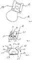
- FIGS. 1 and 3 show a system for detachably fastening a component 1 of an air conditioning and ventilation system.
- the system comprises a holding element 2 and a fastening element 3 which can be attached detachably thereto
- Figures 1 and 3 illustrated system according to the invention around a rail, for example, a ceiling construction.
- a recess 4 is provided in the holding element 2 and is arranged in a tongue-like partial area which is encompassed by two slots 5 on both sides.
- the fastening element 3 is designed as a screw. At one of the two ends of the fastener 3 is a not shown External thread 6 is provided to form a helical thread and at the other end a head region 8 covering an opening 7 of the component 1 to be fastened.
- the external thread 8 is designed as a metric thread.
- the component 1 can be a plate, for example, which is fastened to a holding element 2 from below.
- spacer webs 9 are also provided on the side of the component 1 facing the holding element 2 . In the fastened state, the spacer webs 9 bear against the holding element 2 with their respective upper end.
- the opening 7 is provided in the component 1 , through which the fastening element 3 is passed for fastening the component 1 .
- a counter-element 10 with an internal thread that interacts with the external thread 6 of the fastening element 3 is assigned to the holding element 2 .
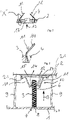
- the counter-element 10 is designed as a separate component in the exemplary embodiments shown.
- the counter-element 10 has two spaced-apart portions 11 that form the internal thread and protrude in the form of webs, which are formed on a base plate 15 .
- Each partial area 11 has a contact area 12 at the end, which interacts with the external thread 6 of the fastening element 3 in the assembled state.
- the partial areas 11 are made of spring steel, so that each partial area 11 and thus also the relevant contact area 12 can be displaced outwards against a spring force. When swiveling outwards, the distance between the contact area 12 and the center line M increases.
- the fastening element 3 can easily be pressed into the internal thread of the counter-element 10 without a tool, viewed in the direction of insertion 13 . This makes assembly easier.
- the fastening means 3 can be unscrewed again counter to the insertion direction 13 in a conventional manner by means of a tool, for example a screwdriver.
- the contact areas 12 of the two sub-areas 11 are offset from one another by half the pitch a, as viewed in the direction of insertion 13 .
- the two contact areas 12 arranged opposite one another thus both engage in the thread turn of the external thread 6 .
- each sub-area 11 in front of the contact area 12, that is to say in the area 14, is beveled as seen in the direction of insertion 13.
- the contact area 12 refers to that part of each of the two sub-areas 11 which is in direct contact with the fastening means 3, ie engages in a thread of the external thread 6, for example.
- each partial area 11 is angled in such a way that, viewed in the direction of insertion 13, the distance from the center line M first increases and then decreases again toward the contact area 12.
- the partial areas 11 of the counter-element 10 are guided through the recess 4 of the holding element 2 from below.
- the recess 4 is designed in such a way that the base plate 15 rests on the edge region of the recess 4 from below, at least in certain areas, after the partial regions 11 have been passed through the recess 4 in the holding element 2 from below. After the later insertion of the fastening element 3, the partial areas 11 spread open as a result prevent the counter-element 10 from accidentally slipping out of the recess 4.
- the clamping force of the partial areas 11 can be influenced by varying the width of the recess 4 in the area on which the partial areas 11 rest will. If a component 1 with a higher weight is to be fastened, a somewhat smaller width of the recess 4 is selected. The partial areas 11 thus lie closer to the edge of the recess 4 or are already prestressed. As a result, a higher force has to be applied when pressing in the fastening means 3, since only a smaller length of each partial area 11 is available for outward displacement or a higher force has to be applied due to the pretension. As a result, in the mounted state, a higher clamping force is exerted by the partial areas 11 on the fastening element 3 . Thus, by selecting the appropriate size of the recess 4, one and the same counter-element 10 can be used for fastening components 1 of different weights.
- the base plate 15 has an opening 16, the partial areas 11 being formed around the opening 16 on the base plate 15.
- the edge of the opening 16 has a collar 17 pointing in the direction of the contact areas 12 in two opposite areas.
- the collars 17 facilitate the insertion of the fastener 3 from below into the internal thread of the counter-element 10.
- the system according to the invention Figures 1 and 2 also has an insertion region 18 that converges in the shape of a funnel, viewed in the direction of insertion 13 and is designed as a separate component.
- the separate component can be fastened to the holding element 2 by means of a fixing device.
- the converging insertion area 18 has, in its area in contact with the holding element 2 , two slot-like holding arms 19 arranged at a distance from one another and pointing towards one another, which grip around the edge of the area of the holding element 2 forming the recess 4 .
- the two partial areas 11 of the counter-element 10 are first guided from below into the recess 4 of the holding element 2, which is open at the bottom and is designed as a rail.
- the converging insertion area 18 which is designed as a separate component, is then moved from below into the holding element 2, which is designed as a rail that opens downwards, in such a way that the slot-like holding arms 19 are pushed by lateral displacement onto the tongue-like partial area with the recess 4 be able.
- the funnel-shaped converging insertion area 18 allows a concealed, simple insertion of the fastening element 3 into the counter-element 10 since the fastening element 3 is guided through the converging insertion area 18 .
- the converging insertion area 18 has on its outside a holding device 20 for an additional element, such as a measuring nipple.
- the holding device 20 consists of two clamping arms between which, for example, a hose can be clamped.
- the holding element 2 has on its underside two spaced-apart slots 21 into which the base plate 15 is inserted with its edge region. No opening 16 is provided in the base plate 15 .
- the holding element 2 also has no recess 4 .
- the fastening element 3 is pressed in the same way into the counter-element 10 for assembly and can be unscrewed again.
Landscapes
- Engineering & Computer Science (AREA)
- Chemical & Material Sciences (AREA)
- Combustion & Propulsion (AREA)
- Mechanical Engineering (AREA)
- General Engineering & Computer Science (AREA)
- Connection Of Plates (AREA)
- Clamps And Clips (AREA)
Claims (18)
- Système de fixation libérable d'une pièce structurelle (1) d'une installation de climatisation et de ventilation, ledit système comprenant un élément de retenue (2), ainsi qu'un élément de fixation (3) pouvant être implanté amoviblement sur ce dernier, sachant, par ailleurs, que ladite pièce structurelle (1) peut être mise en place à l'aide d'au moins un élément de fixation (3) pouvant être guidé à travers un orifice (7) pratiqué dans ladite pièce structurelle (1) à fixer, lequel élément de fixation (3) est muni d'un filetage extérieur (6) à une extrémité, avec formation d'un filet de réalisation hélicoïdale et, à l'autre extrémité, d'une région (8) formant tête et recouvrant au moins partiellement l'orifice (7) de ladite pièce structurelle (1), sachant qu'un élément complémentaire (10), pourvu d'un filetage intérieur et coopérant avec ledit filetage extérieur (6) de l'élément de fixation (3), est associé audit élément de retenue (2), et sachant que l'extrémité dudit élément de fixation (3), dotée dudit filetage extérieur (6), est conçue pour coopérer avec ledit filetage intérieur de l'élément complémentaire (10), à l'état monté, lequel élément complémentaire (10) comporte au moins deux régions partielles (11) distantes l'une de l'autre, faisant saillie en forme de membrures et constituant ledit filetage intérieur, chaque région partielle (11) étant nantie d'une zone de contact (12) préférentiellement située à l'extrémité et coopérant avec l'élément de fixation (3), à l'état monté, et sachant qu'au moins la zone de contact (12) d'au moins une région partielle (11) peut être déplacée vers l'extérieur, en opposition à une force élastique, de façon telle qu'en observant dans la direction d'insertion (13), ledit élément de fixation (3) puisse être enfoncé sans outil dans le filetage intérieur et dévissé, au moyen d'un outil, en sens inverse de ladite direction d'insertion (13), caractérisé par le fait que l'élément complémentaire (10) présente, sur son côté pointant à l'opposé des régions partielles (11), une zone d'introduction (18) à convergence infundibuliforme en observant dans la direction d'insertion (13).
- Système selon la revendication précédente, caractérisé par le fait qu'au moins une région partielle (11) consiste au moins par zones, de préférence intégralement, en de l'acier à ressorts ou en une matière plastique douée d'élasticité.
- Système selon l'une des revendications précédentes, caractérisé par le fait qu'au moins un élément complémentaire (10) fait partie de l'élément de retenue (2).
- Système selon l'une des revendications précédentes, caractérisé par le fait qu'au moins un élément complémentaire (10) est réalisé en tant que pièce structurelle distincte ; et par le fait que les régions partielles (11) sont ménagées solidairement sur une platine d'embase (15).
- Système selon la revendication précédente, caractérisé par le fait que la platine d'embase (15) comporte une ouverture (16) et les régions partielles (11) sont ménagées solidairement, sur ladite platine d'embase (15), tout autour de ladite ouverture (16).
- Système selon la revendication précédente, caractérisé par le fait que le bord de l'ouverture (16) est muni au moins par zones, de préférence intégralement, d'une collerette (17) orientée en direction des zones de contact (12).
- Système selon l'une des revendications précédentes, caractérisé par le fait qu'au moins une région partielle (11) est de réalisation biseautée avant la zone de contact (12) en observant dans la direction d'insertion (13).
- Système selon l'une des revendications précédentes, caractérisé par le fait qu'au moins une région partielle (11) est de réalisation coudée, de façon telle qu'en observant dans la direction d'insertion (13), la distance par rapport à la ligne médiane M croisse, dans un premier temps, et s'amenuise ensuite en direction de la zone de contact (12).
- Système selon l'une des revendications 4 à 8, caractérisé par le fait que l'élément de retenue (2) est pourvu d'un évidement (4) conçu de telle sorte qu'à l'issue du passage des régions partielles (11) à travers ledit évidement (4), la platine d'embase (15) soit en applique, au moins par zones, sur la région marginale dudit évidement (4).
- Système selon l'une des revendications 4 à 8, caractérisé par le fait que l'élément de retenue (2) est muni d'un évidement (4), ainsi que de deux fentes (21) situées sur des côtés opposés dudit évidement (4), dans lesquelles la platine d'embase (15) peut être introduite par sa région marginale.
- Système selon l'une des revendications 4 à 8, caractérisé par le fait que l'élément de retenue (2) est doté de deux fentes (21) situées à distance l'une de l'autre, dans lesquelles la platine d'embase (15) peut être introduite par sa région marginale.
- Système selon l'une des revendications précédentes, caractérisé par le fait qu'en observant dans la direction d'insertion (13), les zones de contact (12) des régions partielles (11) occupent des emplacements mutuellement décalés en concordance avec le pas, de façon telle que chaque zone de contact (12) pénètre dans le filet.
- Système selon l'une des revendications précédentes, caractérisé par le fait que deux régions partielles opposées (11) sont prévues, sachant que les zones de contact (12) desdites deux régions partielles (11) occupent, en observant dans la direction d'insertion (13), des emplacements mutuellement décalés de la moitié du pas.
- Système selon l'une des revendications précédentes, caractérisé par le fait que l'élément de fixation (3) présente un filetage métrique ou un filetage métrique fin en tant que filetage extérieur (6).
- Système selon l'une des revendications précédentes, caractérisé par le fait que l'élément de fixation (3) est réalisé sous la forme d'une vis.
- Système selon l'une des revendications précédentes, caractérisé par le fait que la zone d'introduction (18) convergente est réalisée en tant que pièce structurelle distincte et peut être respectivement fixée à l'élément complémentaire (10), ou à l'élément de retenue (2), au moyen d'un dispositif de blocage à demeure.
- Système selon l'une des revendications précédentes dans la mesure où ces dernières renvoient à la revendication 9, caractérisé par le fait que la zone d'introduction (18) convergente est munie, dans sa région en contact avec l'élément de retenue (2), de deux bras de maintien (19) notamment réalisés à la manière de fentes, situés à distance l'un de l'autre, se faisant mutuellement face et entourant, marginalement, la région dudit élément de retenue (2) qui forme l'évidement (4).
- Système selon l'une des revendications précédentes, caractérisé par le fait que la zone d'introduction (18) convergente est pourvue, de préférence à sa face extérieure, d'au moins un dispositif de maintien (20) dévolu à un élément additionnel tel qu'un raccord de mesure, par exemple.
Applications Claiming Priority (1)
| Application Number | Priority Date | Filing Date | Title |
|---|---|---|---|
| DE202017101384.7U DE202017101384U1 (de) | 2017-03-10 | 2017-03-10 | System zur lösbaren Befestigung eines Bauteils einer klima- und raumlufttechnischen Anlage |
Publications (2)
| Publication Number | Publication Date |
|---|---|
| EP3372916A1 EP3372916A1 (fr) | 2018-09-12 |
| EP3372916B1 true EP3372916B1 (fr) | 2022-11-09 |
Family
ID=59295766
Family Applications (1)
| Application Number | Title | Priority Date | Filing Date |
|---|---|---|---|
| EP18160675.7A Active EP3372916B1 (fr) | 2017-03-10 | 2018-03-08 | Système de fixation amovible d'un composant d'une installation de climatisation et d'aéraulique |
Country Status (3)
| Country | Link |
|---|---|
| EP (1) | EP3372916B1 (fr) |
| DE (1) | DE202017101384U1 (fr) |
| ES (1) | ES2935182T3 (fr) |
Families Citing this family (1)
| Publication number | Priority date | Publication date | Assignee | Title |
|---|---|---|---|---|
| DE202018102853U1 (de) * | 2018-05-22 | 2019-08-27 | Trox Gmbh | Durchlass einer klimatechnischen Anlage zur Be- und/oder zur Entlüftung von Räumen |
Family Cites Families (5)
| Publication number | Priority date | Publication date | Assignee | Title |
|---|---|---|---|---|
| US4508477A (en) * | 1982-09-30 | 1985-04-02 | Eaton Corporation | Fastening device |
| DE102006001741A1 (de) * | 2006-01-13 | 2007-08-02 | A. Raymond Et Cie | Steckmutter |
| JP4738323B2 (ja) * | 2006-12-06 | 2011-08-03 | 株式会社パイオラックス | 締結具 |
| US10197088B2 (en) * | 2011-11-10 | 2019-02-05 | Oldcastle Precast, Inc. | Tamper resistant closure mechanism for a utility vault |
| JP2017187046A (ja) * | 2013-10-03 | 2017-10-12 | ポップリベット・ファスナー株式会社 | スタッド係止具 |
-
2017
- 2017-03-10 DE DE202017101384.7U patent/DE202017101384U1/de active Active
-
2018
- 2018-03-08 ES ES18160675T patent/ES2935182T3/es active Active
- 2018-03-08 EP EP18160675.7A patent/EP3372916B1/fr active Active
Also Published As
| Publication number | Publication date |
|---|---|
| DE202017101384U1 (de) | 2017-06-21 |
| EP3372916A1 (fr) | 2018-09-12 |
| ES2935182T3 (es) | 2023-03-02 |
Similar Documents
| Publication | Publication Date | Title |
|---|---|---|
| EP2136969B1 (fr) | Dispositif de traitement de bandes souples utilisées pour le stockage de vis | |
| WO2010066363A1 (fr) | Dispositif d'écartement et système de fixation avec dispositif d'écartement | |
| EP3586018B1 (fr) | Dispositif de fixation et module de fixation | |
| EP1447576A1 (fr) | Ecrou en plastique pour une unité de construction montrant une percée | |
| DE102012221228A1 (de) | Toleranzausgleichsvorrichtung | |
| EP3643847A1 (fr) | Système de fixation et rail pour un système de fixation | |
| EP2110567A2 (fr) | Dispositif de sécurisation d'une liaison de filetage | |
| EP1775482B1 (fr) | Elément de fixation rapide | |
| EP3372916B1 (fr) | Système de fixation amovible d'un composant d'une installation de climatisation et d'aéraulique | |
| EP3326249B1 (fr) | Agencement comprenant une partie haute de toit et un système de fixation pour la fixation de la partie haute de toit sur le toit d'une armoire électrique | |
| DE4200096A1 (de) | Vorrichtung zum verschliessen einer oeffnung in einer verkleidung | |
| EP3586013B1 (fr) | Module de fixation | |
| DE102007042034A1 (de) | Befestigungssystem zum Befestigen von Bauelementen, insbesondere für Kraftfahrzeuge | |
| DE10063812A1 (de) | Verbindungselement | |
| DE10318023A1 (de) | Schraubelement mit einem angeformten Federelement | |
| DE60314807T2 (de) | Dichtungsvorrichtung | |
| EP3443233B1 (fr) | Clip servant à fixer un premier élément à un deuxième élément | |
| DE2531368B2 (de) | Befestigungsvorrichtung für Haltegriffe, Armlehnen o.dgl. an der Karosserieinnenwand von Fahrzeugen | |
| DE19734601A1 (de) | Lochscheibe | |
| EP0609973B1 (fr) | Dispostif pour fixation des supports de couverture en angle | |
| DE102010018091A1 (de) | Mutter | |
| DE102008025788A1 (de) | Befestigungsklammer | |
| DE102018107083A1 (de) | Befestigungseinrichtung und Verfahren zur Befestigung eines Anbauteils an einem Tragteil, Bauteilsystem und Kraftfahrzeug | |
| DE19849109B4 (de) | Verbindungselement | |
| DE19621665C2 (de) | Vorrichtung zum Befestigen einer Bildröhre |
Legal Events
| Date | Code | Title | Description |
|---|---|---|---|
| PUAI | Public reference made under article 153(3) epc to a published international application that has entered the european phase |
Free format text: ORIGINAL CODE: 0009012 |
|
| STAA | Information on the status of an ep patent application or granted ep patent |
Free format text: STATUS: THE APPLICATION HAS BEEN PUBLISHED |
|
| AK | Designated contracting states |
Kind code of ref document: A1 Designated state(s): AL AT BE BG CH CY CZ DE DK EE ES FI FR GB GR HR HU IE IS IT LI LT LU LV MC MK MT NL NO PL PT RO RS SE SI SK SM TR |
|
| AX | Request for extension of the european patent |
Extension state: BA ME |
|
| STAA | Information on the status of an ep patent application or granted ep patent |
Free format text: STATUS: REQUEST FOR EXAMINATION WAS MADE |
|
| 17P | Request for examination filed |
Effective date: 20190307 |
|
| RBV | Designated contracting states (corrected) |
Designated state(s): AL AT BE BG CH CY CZ DE DK EE ES FI FR GB GR HR HU IE IS IT LI LT LU LV MC MK MT NL NO PL PT RO RS SE SI SK SM TR |
|
| STAA | Information on the status of an ep patent application or granted ep patent |
Free format text: STATUS: EXAMINATION IS IN PROGRESS |
|
| 17Q | First examination report despatched |
Effective date: 20200731 |
|
| STAA | Information on the status of an ep patent application or granted ep patent |
Free format text: STATUS: EXAMINATION IS IN PROGRESS |
|
| GRAP | Despatch of communication of intention to grant a patent |
Free format text: ORIGINAL CODE: EPIDOSNIGR1 |
|
| STAA | Information on the status of an ep patent application or granted ep patent |
Free format text: STATUS: GRANT OF PATENT IS INTENDED |
|
| INTG | Intention to grant announced |
Effective date: 20220601 |
|
| GRAS | Grant fee paid |
Free format text: ORIGINAL CODE: EPIDOSNIGR3 |
|
| GRAA | (expected) grant |
Free format text: ORIGINAL CODE: 0009210 |
|
| STAA | Information on the status of an ep patent application or granted ep patent |
Free format text: STATUS: THE PATENT HAS BEEN GRANTED |
|
| AK | Designated contracting states |
Kind code of ref document: B1 Designated state(s): AL AT BE BG CH CY CZ DE DK EE ES FI FR GB GR HR HU IE IS IT LI LT LU LV MC MK MT NL NO PL PT RO RS SE SI SK SM TR |
|
| REG | Reference to a national code |
Ref country code: GB Ref legal event code: FG4D Free format text: NOT ENGLISH |
|
| REG | Reference to a national code |
Ref country code: CH Ref legal event code: EP Ref country code: AT Ref legal event code: REF Ref document number: 1530613 Country of ref document: AT Kind code of ref document: T Effective date: 20221115 |
|
| REG | Reference to a national code |
Ref country code: DE Ref legal event code: R096 Ref document number: 502018010986 Country of ref document: DE |
|
| REG | Reference to a national code |
Ref country code: IE Ref legal event code: FG4D Free format text: LANGUAGE OF EP DOCUMENT: GERMAN |
|
| REG | Reference to a national code |
Ref country code: NL Ref legal event code: FP |
|
| REG | Reference to a national code |
Ref country code: LT Ref legal event code: MG9D |
|
| REG | Reference to a national code |
Ref country code: ES Ref legal event code: FG2A Ref document number: 2935182 Country of ref document: ES Kind code of ref document: T3 Effective date: 20230302 |
|
| PG25 | Lapsed in a contracting state [announced via postgrant information from national office to epo] |
Ref country code: SE Free format text: LAPSE BECAUSE OF FAILURE TO SUBMIT A TRANSLATION OF THE DESCRIPTION OR TO PAY THE FEE WITHIN THE PRESCRIBED TIME-LIMIT Effective date: 20221109 Ref country code: PT Free format text: LAPSE BECAUSE OF FAILURE TO SUBMIT A TRANSLATION OF THE DESCRIPTION OR TO PAY THE FEE WITHIN THE PRESCRIBED TIME-LIMIT Effective date: 20230309 Ref country code: NO Free format text: LAPSE BECAUSE OF FAILURE TO SUBMIT A TRANSLATION OF THE DESCRIPTION OR TO PAY THE FEE WITHIN THE PRESCRIBED TIME-LIMIT Effective date: 20230209 Ref country code: LT Free format text: LAPSE BECAUSE OF FAILURE TO SUBMIT A TRANSLATION OF THE DESCRIPTION OR TO PAY THE FEE WITHIN THE PRESCRIBED TIME-LIMIT Effective date: 20221109 Ref country code: FI Free format text: LAPSE BECAUSE OF FAILURE TO SUBMIT A TRANSLATION OF THE DESCRIPTION OR TO PAY THE FEE WITHIN THE PRESCRIBED TIME-LIMIT Effective date: 20221109 |
|
| PGFP | Annual fee paid to national office [announced via postgrant information from national office to epo] |
Ref country code: FR Payment date: 20230320 Year of fee payment: 6 |
|
| PG25 | Lapsed in a contracting state [announced via postgrant information from national office to epo] |
Ref country code: RS Free format text: LAPSE BECAUSE OF FAILURE TO SUBMIT A TRANSLATION OF THE DESCRIPTION OR TO PAY THE FEE WITHIN THE PRESCRIBED TIME-LIMIT Effective date: 20221109 Ref country code: PL Free format text: LAPSE BECAUSE OF FAILURE TO SUBMIT A TRANSLATION OF THE DESCRIPTION OR TO PAY THE FEE WITHIN THE PRESCRIBED TIME-LIMIT Effective date: 20221109 Ref country code: LV Free format text: LAPSE BECAUSE OF FAILURE TO SUBMIT A TRANSLATION OF THE DESCRIPTION OR TO PAY THE FEE WITHIN THE PRESCRIBED TIME-LIMIT Effective date: 20221109 Ref country code: IS Free format text: LAPSE BECAUSE OF FAILURE TO SUBMIT A TRANSLATION OF THE DESCRIPTION OR TO PAY THE FEE WITHIN THE PRESCRIBED TIME-LIMIT Effective date: 20230309 Ref country code: HR Free format text: LAPSE BECAUSE OF FAILURE TO SUBMIT A TRANSLATION OF THE DESCRIPTION OR TO PAY THE FEE WITHIN THE PRESCRIBED TIME-LIMIT Effective date: 20221109 Ref country code: GR Free format text: LAPSE BECAUSE OF FAILURE TO SUBMIT A TRANSLATION OF THE DESCRIPTION OR TO PAY THE FEE WITHIN THE PRESCRIBED TIME-LIMIT Effective date: 20230210 |
|
| P01 | Opt-out of the competence of the unified patent court (upc) registered |
Effective date: 20230517 |
|
| PG25 | Lapsed in a contracting state [announced via postgrant information from national office to epo] |
Ref country code: SM Free format text: LAPSE BECAUSE OF FAILURE TO SUBMIT A TRANSLATION OF THE DESCRIPTION OR TO PAY THE FEE WITHIN THE PRESCRIBED TIME-LIMIT Effective date: 20221109 Ref country code: RO Free format text: LAPSE BECAUSE OF FAILURE TO SUBMIT A TRANSLATION OF THE DESCRIPTION OR TO PAY THE FEE WITHIN THE PRESCRIBED TIME-LIMIT Effective date: 20221109 Ref country code: EE Free format text: LAPSE BECAUSE OF FAILURE TO SUBMIT A TRANSLATION OF THE DESCRIPTION OR TO PAY THE FEE WITHIN THE PRESCRIBED TIME-LIMIT Effective date: 20221109 Ref country code: DK Free format text: LAPSE BECAUSE OF FAILURE TO SUBMIT A TRANSLATION OF THE DESCRIPTION OR TO PAY THE FEE WITHIN THE PRESCRIBED TIME-LIMIT Effective date: 20221109 Ref country code: CZ Free format text: LAPSE BECAUSE OF FAILURE TO SUBMIT A TRANSLATION OF THE DESCRIPTION OR TO PAY THE FEE WITHIN THE PRESCRIBED TIME-LIMIT Effective date: 20221109 |
|
| PGFP | Annual fee paid to national office [announced via postgrant information from national office to epo] |
Ref country code: IT Payment date: 20230331 Year of fee payment: 6 Ref country code: ES Payment date: 20230414 Year of fee payment: 6 Ref country code: CH Payment date: 20230402 Year of fee payment: 6 |
|
| REG | Reference to a national code |
Ref country code: DE Ref legal event code: R097 Ref document number: 502018010986 Country of ref document: DE |
|
| PG25 | Lapsed in a contracting state [announced via postgrant information from national office to epo] |
Ref country code: SK Free format text: LAPSE BECAUSE OF FAILURE TO SUBMIT A TRANSLATION OF THE DESCRIPTION OR TO PAY THE FEE WITHIN THE PRESCRIBED TIME-LIMIT Effective date: 20221109 Ref country code: AL Free format text: LAPSE BECAUSE OF FAILURE TO SUBMIT A TRANSLATION OF THE DESCRIPTION OR TO PAY THE FEE WITHIN THE PRESCRIBED TIME-LIMIT Effective date: 20221109 |
|
| PLBE | No opposition filed within time limit |
Free format text: ORIGINAL CODE: 0009261 |
|
| STAA | Information on the status of an ep patent application or granted ep patent |
Free format text: STATUS: NO OPPOSITION FILED WITHIN TIME LIMIT |
|
| 26N | No opposition filed |
Effective date: 20230810 |
|
| PG25 | Lapsed in a contracting state [announced via postgrant information from national office to epo] |
Ref country code: MC Free format text: LAPSE BECAUSE OF FAILURE TO SUBMIT A TRANSLATION OF THE DESCRIPTION OR TO PAY THE FEE WITHIN THE PRESCRIBED TIME-LIMIT Effective date: 20221109 |
|
| PG25 | Lapsed in a contracting state [announced via postgrant information from national office to epo] |
Ref country code: SI Free format text: LAPSE BECAUSE OF FAILURE TO SUBMIT A TRANSLATION OF THE DESCRIPTION OR TO PAY THE FEE WITHIN THE PRESCRIBED TIME-LIMIT Effective date: 20221109 |
|
| REG | Reference to a national code |
Ref country code: BE Ref legal event code: MM Effective date: 20230331 |
|
| PG25 | Lapsed in a contracting state [announced via postgrant information from national office to epo] |
Ref country code: LU Free format text: LAPSE BECAUSE OF NON-PAYMENT OF DUE FEES Effective date: 20230308 |
|
| REG | Reference to a national code |
Ref country code: IE Ref legal event code: MM4A |
|
| PG25 | Lapsed in a contracting state [announced via postgrant information from national office to epo] |
Ref country code: IE Free format text: LAPSE BECAUSE OF NON-PAYMENT OF DUE FEES Effective date: 20230308 |
|
| PG25 | Lapsed in a contracting state [announced via postgrant information from national office to epo] |
Ref country code: BE Free format text: LAPSE BECAUSE OF NON-PAYMENT OF DUE FEES Effective date: 20230331 |
|
| PGFP | Annual fee paid to national office [announced via postgrant information from national office to epo] |
Ref country code: NL Payment date: 20240320 Year of fee payment: 7 |
|
| PGFP | Annual fee paid to national office [announced via postgrant information from national office to epo] |
Ref country code: AT Payment date: 20240318 Year of fee payment: 7 |
|
| PGFP | Annual fee paid to national office [announced via postgrant information from national office to epo] |
Ref country code: DE Payment date: 20240118 Year of fee payment: 7 Ref country code: GB Payment date: 20240322 Year of fee payment: 7 |