EP2369184A2 - Device with self-actuated compensation of production or installation-related tolerances for resting one component on a second component - Google Patents
Device with self-actuated compensation of production or installation-related tolerances for resting one component on a second component Download PDFInfo
- Publication number
- EP2369184A2 EP2369184A2 EP11000177A EP11000177A EP2369184A2 EP 2369184 A2 EP2369184 A2 EP 2369184A2 EP 11000177 A EP11000177 A EP 11000177A EP 11000177 A EP11000177 A EP 11000177A EP 2369184 A2 EP2369184 A2 EP 2369184A2
- Authority
- EP
- European Patent Office
- Prior art keywords
- component
- supporting
- adjusting element
- thread
- adjusting
- Prior art date
- Legal status (The legal status is an assumption and is not a legal conclusion. Google has not performed a legal analysis and makes no representation as to the accuracy of the status listed.)
- Withdrawn
Links
- 238000004519 manufacturing process Methods 0.000 title claims description 6
- 230000000284 resting effect Effects 0.000 title description 2
- 238000009434 installation Methods 0.000 title 1
- 239000004033 plastic Substances 0.000 claims description 3
- 230000002401 inhibitory effect Effects 0.000 claims description 2
- 239000002184 metal Substances 0.000 claims description 2
- 239000012815 thermoplastic material Substances 0.000 claims description 2
- 230000001747 exhibiting effect Effects 0.000 claims 2
- 238000003892 spreading Methods 0.000 description 8
- VYZAMTAEIAYCRO-UHFFFAOYSA-N Chromium Chemical compound [Cr] VYZAMTAEIAYCRO-UHFFFAOYSA-N 0.000 description 3
- 238000005553 drilling Methods 0.000 description 2
- 238000004026 adhesive bonding Methods 0.000 description 1
- 230000000903 blocking effect Effects 0.000 description 1
- 230000001143 conditioned effect Effects 0.000 description 1
- 230000001419 dependent effect Effects 0.000 description 1
- 230000006866 deterioration Effects 0.000 description 1
- 238000011161 development Methods 0.000 description 1
- 230000018109 developmental process Effects 0.000 description 1
- 238000010586 diagram Methods 0.000 description 1
- 238000006073 displacement reaction Methods 0.000 description 1
- 230000035515 penetration Effects 0.000 description 1
- 238000007788 roughening Methods 0.000 description 1
- 238000007665 sagging Methods 0.000 description 1
- 230000000007 visual effect Effects 0.000 description 1
Images
Classifications
-
- F—MECHANICAL ENGINEERING; LIGHTING; HEATING; WEAPONS; BLASTING
- F16—ENGINEERING ELEMENTS AND UNITS; GENERAL MEASURES FOR PRODUCING AND MAINTAINING EFFECTIVE FUNCTIONING OF MACHINES OR INSTALLATIONS; THERMAL INSULATION IN GENERAL
- F16B—DEVICES FOR FASTENING OR SECURING CONSTRUCTIONAL ELEMENTS OR MACHINE PARTS TOGETHER, e.g. NAILS, BOLTS, CIRCLIPS, CLAMPS, CLIPS OR WEDGES; JOINTS OR JOINTING
- F16B5/00—Joining sheets or plates, e.g. panels, to one another or to strips or bars parallel to them
- F16B5/02—Joining sheets or plates, e.g. panels, to one another or to strips or bars parallel to them by means of fastening members using screw-thread
- F16B5/025—Joining sheets or plates, e.g. panels, to one another or to strips or bars parallel to them by means of fastening members using screw-thread specially designed to compensate for misalignement or to eliminate unwanted play
-
- F—MECHANICAL ENGINEERING; LIGHTING; HEATING; WEAPONS; BLASTING
- F16—ENGINEERING ELEMENTS AND UNITS; GENERAL MEASURES FOR PRODUCING AND MAINTAINING EFFECTIVE FUNCTIONING OF MACHINES OR INSTALLATIONS; THERMAL INSULATION IN GENERAL
- F16B—DEVICES FOR FASTENING OR SECURING CONSTRUCTIONAL ELEMENTS OR MACHINE PARTS TOGETHER, e.g. NAILS, BOLTS, CIRCLIPS, CLAMPS, CLIPS OR WEDGES; JOINTS OR JOINTING
- F16B33/00—Features common to bolt and nut
- F16B33/006—Non-metallic fasteners using screw-thread
Definitions
- the present invention relates to a device for supporting a first component on a second component with automatic compensation of manufacturing and assembly-related tolerances between the two components.
- the above-mentioned adjustment devices are not suitable.
- an interior trim of a radiator grille which has means for supporting, wherein the inner lining is provided for positioning the grille.
- the means for supporting are around a arranged on the inner lining of the grille support on which rests the grille.
- the device according to the invention for supporting a first component on a second component is designed so that an automatic compensation of manufacturing and assembly-related tolerances between the two components takes place when using the device.
- the device consists of a receiving element and an adjusting element, wherein the adjusting element is at least partially formed as a threaded rod and at its first provided with an external thread upper end has a bore for receiving an adjusting screw, while at its second lower end a support surface is arranged.
- the receiving element is provided for receiving the adjusting element and has a continuous Bore, which is at least partially equipped with an internal thread.
- the operating principle of the device is based on the fact that the receiving element is either firmly connected to the first component to be supported or even part of the first component to be supported.
- the device is designed as a separate component and connected via the receiving element with the first component to be supported.
- the connection to the second component takes place via the support surface of the adjusting element, which is provided for mounting or resting on the supporting second component.
- the device for supporting connected to a corresponding inner lining to be supported or be part of this inner lining.
- At least two longitudinal slots are provided which allow for a corresponding penetration of the screw into the borehole spreading of the adjusting element in this area.
- the adjusting element as at least two, arranged transversely to the thread pitch in the thread teeth, while the receiving element has a counterpart in the axial direction on the flank of the internal thread arranged transversely to the thread pitch, which serves as a corresponding receptacle for the above in the thread of the Adjusting element arranged teeth is provided.
- Both adjusting element and receiving element are usually made of a thermoplastic material, wherein in this context it should be mentioned that the device Generally intended for use with plastic components.
- a metal screw is preferably provided which engages in the bore at the upper end of the adjusting element and advantageously has a plastic-compatible or symmetrical thread, while the tip of the adjusting screw is preferably formed without a thread, in the form of a tip of a nail.
- the support device based on the fact that first the adjusting element, which is partially formed as a threaded rod and having an external thread in its upper region, in the receiving element, which has a provided with an internal thread, through hole, is screwed.
- the receiving element is firmly connected to the first component to be supported or is part of the first component to be supported.
- the support surface which is arranged at the lower end of the adjusting element, at a defined distance of, for example, about 3 to 15 mm to the supporting second component.
- the adjusting screw is screwed into the bore at the upper end of the adjusting element, wherein the entire adjusting element is first screwed into the receiving element by the higher frictional engagement of the screw in the bore in the adjustment until the support surface comes to rest on the supporting second component.
- the frictional engagement of the adjusting element with the supporting surface on the supporting component is greater than that of the screw in the bore, so that the screw is now screwed further into the adjusting element.
- the screw continues to penetrate into the bore until the clamping region is reached, which passes through the at least two axially extending slots in the adjusting element in the region of Bore is characterized, which allow a spreading of the adjusting element.
- at least two transversely to the thread profile in the thread arranged axially extending teeth of the adjusting element further spreading is inhibited during spreading of the adjusting element and the adjusting element is secured against further adjustment.
- this type of support creates a bias between the two components. This is often desired, for example, to counteract in advance the unwanted setting behavior of plastic parts.
- a high bias be undesirable, so can in an advantageous embodiment of the present invention by gluing the support surface of the adjusting element with a slide-inhibiting film such.
- a PU film with a rough surface or by direct roughening of the surface of the support surface of the frictional engagement between the support surface and the second component can be increased, so that the blocking of the adjusting screw takes place earlier.
- An example of an advantageous application of the present invention is the support of a bumper combined with a radiator grille in the front end region of a vehicle.
- high demands are placed on the visual appearance, which, for example, find their expression in the fact that the radiator grille is allowed to lower at a maximum load even by a predetermined value.
- the support device has the additional advantage that it is inexpensive to produce, no additional adjustment or adjustment operations for the vehicle manufacturer conditioned and, above all, does not bring about any deterioration of the legal requirements, in particular with regard to pedestrian protection.
- the supporting device is firmly connected only to the first component to be supported, namely the radiator grille, and merely rests on the cross member, a displacement on the cross member is possible in the event of an impact, so that no additional resistance is built up by the supporting device Reason of the pedestrian protection could possibly be reduced.
- the device according to the invention has been developed primarily for use in the automotive sector and can be used particularly advantageously in the front end area to the visible components used there, such. B. grille or bumper relative to other components set and fix.
- B. grille or bumper relative to other components set and fix is not to be seen as a restriction, since the supporting device according to the invention can generally be used more advantageously where a first component is to be supported on a second component, thereby ensuring and fixing the relative position to one another or to a third component.
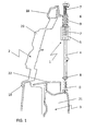
- FIG. 1 showing a sectional view of a portion of a front end structure of a motor vehicle
- the supporting device 1 consists essentially of an adjusting element 4 and a receiving element 5.
- the position drawn with a solid line corresponds to the state of the supporting device 1 before its use, which can be recognized by the fact that there is a distance D between the supporting surface 8 and the supporting component 3, which is relatively large in the present case, since the support device 1 must be performed during assembly of the radiator grille on the cover 22 of the cross member 21.
- the distance D (adjustment) is about 3 to 15 mm, preferably about 6 mm.
- the upper end of the adjusting element 4 projects with the external thread 9 out of the receiving element 5.
- the adjusting element 4 is first screwed into the receiving element 5 due to the higher frictional engagement of the adjusting screw 7 in the bore 6 until the bearing surface 8 comes to rest on the supporting second component 3. This state is shown with a broken line in the present illustration. In this position, the upper end of the adjusting element 4 with the external thread 9 is completely absorbed by the receiving element 5, which is shown in dashed lines. The adjusting screw 7 is now completely screwed into the adjusting element 4, which is also shown in dashed lines.
- a chrome frame 18 can still be seen, which is to be regarded as the third component to which the first component 2 to be supported is to be relatively aligned.
- the supporting device 1 With the aid of the supporting device 1 according to the invention, it is now possible to prevent settling or sinking of the first component 2 to be supported, namely the radiator grille 20, even under continuous load relative to a third component.
- a cover 22 for the bumper cross member 21, which acts as a supporting second component 3 can still be seen in the selected illustration.
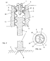
- FIG. 2 shows a longitudinal section through portions of the supporting device 1 according to the invention, based on which the Functioning of the device to be explained, which consists essentially of an adjusting element 4 and a receiving element 5.
- the adjusting element 4 is partially formed as a threaded rod and has at its upper end an external thread 9, which is formed to match the internal thread 10 of the through hole 11 of the receiving element 5.
- the adjusting element 4 has in its upper end a bore 6 into which the adjusting screw 7 engages.
- longitudinal slots 12 arranged in the axial direction are provided in the area of influence of the adjusting screw 7, which allow a spreading of the adjusting element 4 in this area when the adjusting screw 7 is screwed in.
- the lower end of the adjusting element 4 is formed by the support surface 8, which comes after the final assembly of the device according to the invention on the supporting member 3 to the plant, while the component 2 to be supported is firmly connected to the receiving element 4.
- FIG. 2a is a plan view of the section through the shifted plane AA in the FIG. 2 shows.
- the core of the adjusting element 4 is arranged in the receiving element 5, which can be seen in the thread 14 of the external thread 9 of the adjusting element 4 arranged transversely to the thread path teeth 13, which made possible when tightening the screw 7 due to the through the slots 12 Spreading of the adjusting element 4 are pressed into the teeth 14 arranged on the thread flank 16 of the internal thread 10 of the receiving element 5.
- This state which is achieved when the adjusting screw 7 is completely screwed into the bore 6 of the adjusting element 4, is in the present illustration with a rendered broken line. In this position, the adjusting element 4 is secured against further adjustment.
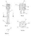
- FIG. 3 shows a side view of an equipped in its upper part with an external thread 9 adjustment 4.
- the bore 6 for receiving the adjusting screw 7 is invisible in this illustration and therefore shown in dashed lines.
- the longitudinal body of the adjusting element 4 has a special configuration in the form of a cross profile, on which the support surface 8 is arranged in the lower end of the adjusting element 4.
- FIG. 4 also shows a side view of a portion of the adjusting element 4, wherein the view compared to FIG. 3 rotated by 90 °, so that in this view, the slots 12 can be seen, which are positioned in the region of the external thread 9 of the adjusting element 4 and allow spreading of the adjusting element 4 in this area when screwing the adjusting screw 7 in the bore 6.
- the teeth 13 can be seen, which are arranged transversely to the external thread 9 in the thread 14 and are pressed during spreading of the adjusting element 4 to the outside.
- the FIG. 4a shows a plan view of the adjustment 4 from FIG.
Abstract
Description
Die vorliegende Erfindung betrifft eine Vorrichtung zum Abstützen eines ersten Bauteils an einem zweiten Bauteil mit selbsttätigem Ausgleich von fertigungs- und montagebedingten Toleranzen zwischen den beiden Bauteilen.The present invention relates to a device for supporting a first component on a second component with automatic compensation of manufacturing and assembly-related tolerances between the two components.
Es sind zahlreiche Vorrichtungen bekannt, mit deren Hilfe Bauteile aneinander angeglichen werden, wobei diese Vorrichtung insbesondere in der Möbel- oder Automobilindustrie Anwendung finden, wo großflächige Bauteile mit optisch einwandfreien Fugen zueinander angeordnet werden müssen. Derartige Vorrichtungen werden beispielsweise in der
In der
Es besteht somit weiterhin das Problem, eine Vorrichtung zu finden, die die Nachteile des Standes der Technik nicht aufweist und insbesondere dafür geeignet ist, ein erstes Bauteil an einem zweiten Bauteil mit selbsttätigem Ausgleich von fertigungs- und montagebedingten Toleranzen abzustützen, um auf diese Weise ein Absinken oder Absetzen des ersten Bauteils zu verhindern und damit die Anordnung des ersten Bauteils relativ zu einem dritten Bauteil auch bei einer Dauerbelastung zu sichern.Thus, there is still the problem of finding a device which does not have the disadvantages of the prior art and in particular is suitable for supporting a first component on a second component with automatic compensation of manufacturing and assembly-related tolerances in order in this way To prevent sagging or settling of the first component and thus to secure the arrangement of the first component relative to a third component even with a continuous load.
Gelöst wird die Aufgabe durch eine Vorrichtung mit den Merkmalen des Anspruchs 1. Vorteilhafte Ausgestaltungen und Weiterentwicklungen der Vorrichtung sind Gegenstand der Unteransprüche.The object is achieved by a device having the features of
Die erfindungsgemäße Vorrichtung zum Abstützen eines ersten Bauteils an einem zweiten Bauteil ist so konzipiert, dass ein selbsttätiger Ausgleich von fertigungs- und montagebedingten Toleranzen zwischen den beiden Bauteilen beim Einsatz der Vorrichtung stattfindet. Dabei besteht die Vorrichtung aus einem Aufnahmeelement und einem Verstellelement, wobei das Verstellelement zumindest teilweise als Gewindestange ausgebildet ist und an seinem ersten mit einem Außengewinde versehenen oberen Ende eine Bohrung zur Aufnahme einer Verstellschraube aufweist, während an seinem zweiten unteren Ende eine Abstützfläche angeordnet ist. Das Aufnahmeelement ist zur Aufnahme des Verstellelements vorgesehen und besitzt dafür eine durchgehende Bohrung, die zumindest teilweise mit einem Innengewinde ausgestattet ist.The device according to the invention for supporting a first component on a second component is designed so that an automatic compensation of manufacturing and assembly-related tolerances between the two components takes place when using the device. The device consists of a receiving element and an adjusting element, wherein the adjusting element is at least partially formed as a threaded rod and at its first provided with an external thread upper end has a bore for receiving an adjusting screw, while at its second lower end a support surface is arranged. The receiving element is provided for receiving the adjusting element and has a continuous Bore, which is at least partially equipped with an internal thread.
Das Funktionsprinzip der Vorrichtung beruht darauf, dass das Aufnahmeelement entweder fest mit dem abzustützenden ersten Bauteil verbunden ist oder sogar Teil des abzustützenden ersten Bauteils ist. Im ersten Fall ist die Vorrichtung als separates Bauteil ausgebildet und über das Aufnahmeelement mit dem abzustützenden ersten Bauteil verbunden. Die Verbindung zum zweiten Bauteil erfolgt über die Abstützfläche des Verstellelements, die zur Auf- bzw. Anlage auf dem stützenden zweiten Bauteil vorgesehen ist. So kann beispielsweise die Vorrichtung zum Abstützen mit einer entsprechenden abzustützenden Innenverkleidung verbunden oder auch ein Teil dieser Innenverkleidung sein.The operating principle of the device is based on the fact that the receiving element is either firmly connected to the first component to be supported or even part of the first component to be supported. In the first case, the device is designed as a separate component and connected via the receiving element with the first component to be supported. The connection to the second component takes place via the support surface of the adjusting element, which is provided for mounting or resting on the supporting second component. Thus, for example, the device for supporting connected to a corresponding inner lining to be supported or be part of this inner lining.
Im oberen, mit einem Außengewinde versehenen Bereich des Verstellelements, im Bereich der Bohrung für die Verstellschraube, sind mindestens zwei Längsschlitze vorgesehen, die bei entsprechendem Eindringen der Schraube ins Bohrloch ein Aufspreizen des Verstellelements in diesem Bereich ermöglichen.In the upper, provided with an external thread portion of the adjusting element, in the region of the bore for the adjusting screw, at least two longitudinal slots are provided which allow for a corresponding penetration of the screw into the borehole spreading of the adjusting element in this area.
Darüber hinaus weist das Verstellelement als mindestens zwei, quer zum Gewindeverlauf im Gewindegang angeordnete Zähne auf, während das Aufnahmeelement als Gegenstück eine in axialer Richtung auf der Flanke des Innengewindes quer zum Gewindeverlauf angeordnete Verzahnung aufweist, die als korrespondierende Aufnahme für die oben genannten im Gewindegang des Verstellelements angeordneten Zähne vorgesehen ist.In addition, the adjusting element as at least two, arranged transversely to the thread pitch in the thread teeth, while the receiving element has a counterpart in the axial direction on the flank of the internal thread arranged transversely to the thread pitch, which serves as a corresponding receptacle for the above in the thread of the Adjusting element arranged teeth is provided.
Sowohl Verstellelement als auch Aufnahmeelement sind üblicherweise aus einem thermoplastischen Kunststoff gefertigt, wobei in diesem Zusammenhang erwähnt werden soll, dass die Vorrichtung generell vor allem für den Einsatz bei Bauteilen aus Kunststoff vorgesehen ist.Both adjusting element and receiving element are usually made of a thermoplastic material, wherein in this context it should be mentioned that the device Generally intended for use with plastic components.
Als Verstellschraube ist vorzugsweise eine Metallschraube vorgesehen, die in die Bohrung am oberen Ende des Verstellelementes eingreift und vorteilhaft ein kunststoffgerechtes bzw. symmetrisches Gewinde aufweist, während die Spitze der Verstellschraube vorzugsweise ohne Gewinde, in Form einer Spitze eines Nagels ausgebildet ist.As an adjusting screw, a metal screw is preferably provided which engages in the bore at the upper end of the adjusting element and advantageously has a plastic-compatible or symmetrical thread, while the tip of the adjusting screw is preferably formed without a thread, in the form of a tip of a nail.
Die Funktionsweise der Abstützvorrichtung beruht darauf, dass zunächst das Verstellelement, das teilweise als Gewindestange ausgebildet ist und in seinem oberen Bereich ein Außengewinde aufweist, in das Aufnahmeelement, das eine mit einem Innengewinde ausgestattete, durchgehende Bohrung aufweist, eingedreht wird. Das Aufnahmeelement ist dabei fest mit dem abzustützenden ersten Bauteil verbunden bzw. ist ein Teil des abzustützenden ersten Bauteils. Nach dem Eindrehen des Verstellelements befindet sich die Abstützfläche, die an dem unteren Ende des Verstellelementes angeordnet ist, in einem definierten Abstand von beispielsweise ca. 3 bis 15 mm zum stützenden zweiten Bauteil. Nun wird die Verstellschraube in die Bohrung am oberen Ende des Verstellelements eingedreht, wobei durch den höheren Reibschluss der Schraube in der Bohrung im Verstellelement zunächst das gesamte Verstellelement in das Aufnahmeelement eingedreht wird, bis die Abstützfläche auf dem stützenden zweiten Bauteil zur Anlage kommt. Nun ist der Reibschluss des Verstellelementes mit der Abstützfläche auf dem stützenden Bauteil größer als der der Schraube in der Bohrung, sodass die Schraube nun weiter in das Verstellelement eingedreht wird. Die Schraube dringt weiter in die Bohrung ein, bis der Klemmbereich erreicht ist, der durch die mindestens beiden axial verlaufenden Schlitze im Verstellelement im Bereich der Bohrung charakterisiert ist, die ein Aufspreizen des Verstellelementes ermöglichen. Durch die ebenfalls mindestens zwei quer zum Gewindeverlauf im Gewindegang angeordneten axial verlaufenden Zähne des Verstellelements wird beim Aufspreizen des Verstellelements das weitere Eindrehen gehemmt und das Verstellelement wird so gegen ein weiteres Verstellen gesichert.The operation of the support device based on the fact that first the adjusting element, which is partially formed as a threaded rod and having an external thread in its upper region, in the receiving element, which has a provided with an internal thread, through hole, is screwed. The receiving element is firmly connected to the first component to be supported or is part of the first component to be supported. After screwing in the adjustment, the support surface, which is arranged at the lower end of the adjusting element, at a defined distance of, for example, about 3 to 15 mm to the supporting second component. Now, the adjusting screw is screwed into the bore at the upper end of the adjusting element, wherein the entire adjusting element is first screwed into the receiving element by the higher frictional engagement of the screw in the bore in the adjustment until the support surface comes to rest on the supporting second component. Now, the frictional engagement of the adjusting element with the supporting surface on the supporting component is greater than that of the screw in the bore, so that the screw is now screwed further into the adjusting element. The screw continues to penetrate into the bore until the clamping region is reached, which passes through the at least two axially extending slots in the adjusting element in the region of Bore is characterized, which allow a spreading of the adjusting element. By also at least two transversely to the thread profile in the thread arranged axially extending teeth of the adjusting element further spreading is inhibited during spreading of the adjusting element and the adjusting element is secured against further adjustment.
Konstruktionsbedingt erzeugt diese Art der Abstützung eine Vorspannung zwischen den beiden Bauteilen. Dies wird häufig gewünscht, um beispielsweise im Vorfeld dem unerwünschten Setzverhalten von Kunststoffteilen entgegenzuwirken. Sollte dagegen eine hohe Vorspannung unerwünscht sein, so kann bei einer vorteilhaften Ausgestaltung der vorliegenden Erfindung durch Bekleben der Abstützfläche des Verstellelementes mit einer gleithemmenden Folie, wie z. B. einer PU-Folie mit rauer Oberfläche, oder durch direktes Aufrauen der Oberfläche der Abstützfläche der Reibschluss zwischen Abstützfläche und dem zweiten Bauteil erhöht werden, sodass die Blockierung der Verstellschraube früher erfolgt.By design, this type of support creates a bias between the two components. This is often desired, for example, to counteract in advance the unwanted setting behavior of plastic parts. On the other hand, should a high bias be undesirable, so can in an advantageous embodiment of the present invention by gluing the support surface of the adjusting element with a slide-inhibiting film such. As a PU film with a rough surface, or by direct roughening of the surface of the support surface of the frictional engagement between the support surface and the second component can be increased, so that the blocking of the adjusting screw takes place earlier.
Ein Beispiel für eine vorteilhafte Anwendung der vorliegenden Erfindung ist die Abstützung eines mit einem Kühlerschutzgitter kombinierten Stoßfängers im Frontendbereich eines Fahrzeugs. Hier werden hohe Anforderungen an das optische Erscheinungsbild gestellt, die beispielsweise ihren Ausdruck darin finden, dass das Kühlerschutzgitter sich auch bei einer Dauerbelastung maximal um einen vorgegebenen Wert absenken darf. Im Rahmen der vorliegenden Arbeiten wurde gefunden, dass mit Hilfe der erfindungsgemäßen Abstützvorrichtung die Lastenheftvorgaben für diesen Montagebereich problemlos erfüllt werden können, wobei die Abstützvorrichtung den zusätzlichen Vorteil hat, dass sie kostengünstig herstellbar ist, keine zusätzlichen Justier― oder Einstellvorgänge für den Fahrzeughersteller bedingt und vor allem auch keine Verschlechterung der gesetzlichen Anforderungen insbesondere in Bezug auf Fußgängerschutz mit sich bringt. Dadurch, dass die Abstützvorrichtung nur mit dem abzustützenden ersten Bauteil, nämlich dem Kühlerschutzgitter, fest verbunden ist, und auf dem Querträger lediglich aufsitzt, ist im Falle eines Aufpralls eine Verschiebung auf dem Querträger möglich, sodass durch die Abstützvorrichtung kein zusätzlicher Widerstand aufgebaut wird, auf Grund dessen der Fußgängerschutz eventuell gemindert werden könnte.An example of an advantageous application of the present invention is the support of a bumper combined with a radiator grille in the front end region of a vehicle. Here, high demands are placed on the visual appearance, which, for example, find their expression in the fact that the radiator grille is allowed to lower at a maximum load even by a predetermined value. In the context of the present work it has been found that with the aid of the support device according to the invention the specifications can be easily met for this assembly area, wherein the support device has the additional advantage that it is inexpensive to produce, no additional adjustment or adjustment operations for the vehicle manufacturer conditioned and, above all, does not bring about any deterioration of the legal requirements, in particular with regard to pedestrian protection. Due to the fact that the supporting device is firmly connected only to the first component to be supported, namely the radiator grille, and merely rests on the cross member, a displacement on the cross member is possible in the event of an impact, so that no additional resistance is built up by the supporting device Reason of the pedestrian protection could possibly be reduced.
Zwar wurde die erfindungsgemäße Vorrichtung primär für den Einsatz im Automobilbereich entwickelt und kann besonders vorteilhaft im Frontendbereich eingesetzt werden, um die dort eingesetzten sichtbaren Bauteile, wie z. B. Kühlergrill oder Stoßfänger relativ zu weiteren Bauteilen einzustellen und zu fixieren. Darin ist jedoch keine Einschränkung zu sehen, denn die erfindungsgemäße Abstützvorrichtung kann allgemein dort vorteilhafter eingesetzt werden, wo ein erstes Bauteil an einem zweiten Bauteil abgestützt werden soll, um dadurch die relative Lage zueinander bzw. zu einem dritten Bauteil sicherzustellen und zu fixieren.Although the device according to the invention has been developed primarily for use in the automotive sector and can be used particularly advantageously in the front end area to the visible components used there, such. B. grille or bumper relative to other components set and fix. However, this is not to be seen as a restriction, since the supporting device according to the invention can generally be used more advantageously where a first component is to be supported on a second component, thereby ensuring and fixing the relative position to one another or to a third component.
Im Folgenden wird die vorliegende Erfindung anhand von Zeichnungen ausführlich erläutert. Dabei zeigen
- Fig. 1
- eine Schnittdarstellung eines Ausschnitts aus dem Frontendbereich eines Kraftfahrzeugs,
- Fig. 2
- eine Schnittdarstellung der erfindungsgemäßen Vorrichtung zum Abstützen,
- Fig. 2a
- eine Darstellung des Schnittes in der versetzten Ebene A-A der
Figur 2 - Fig. 3
- das Verstellelement als separates Bauteil,
- Fig. 3a
- eine Draufsicht auf einen Schnitt durch die Ebene A-A in
Figur 3 - Fig. 4
- einen Teilbereich des Verstellelements und
- Fig. 4a
- eine Draufsicht auf das Verstellelement aus
Figur 4
- Fig. 1
- a sectional view of a section of the front end of a motor vehicle,
- Fig. 2
- a sectional view of the device according to the invention for supporting,
- Fig. 2a
- a representation of the section in the offset plane AA the
FIG. 2 . - Fig. 3
- the adjusting element as a separate component,
- Fig. 3a
- a plan view of a section through the plane AA in
FIG. 3 . - Fig. 4
- a portion of the adjustment and
- Fig. 4a
- a plan view of the adjustment of
FIG. 4 .
In der
Durch das Drehen der Verstellschraube 7 wird auf Grund des höheren Reibschlusses der Verstellschraube 7 in der Bohrung 6 zunächst das Verstellelement 4 in das Aufnahmeelement 5 eingedreht, bis die Auflagefläche 8 auf dem stützenden zweiten Bauteil 3 zur Anlage kommt. Dieser Zustand ist bei der vorliegenden Darstellung mit unterbrochener Linie dargestellt. In dieser Position ist das obere Ende des Verstellelements 4 mit dem Außengewinde 9 vollständig von dem Aufnahmeelement 5 aufgenommen, was gestrichelt dargestellt ist. Die Verstellschraube 7 ist jetzt vollständig in das Verstellelement 4 eingedreht, was ebenfalls gestrichelt wiedergegeben ist.By turning the adjusting
Im Folgenden soll nur noch kurz auf übrigen bei dieser Darstellung gezeigten Bauteile eingegangen werden, während die Funktionsweise der erfindungsgemäßen Vorrichtung an den nachfolgenden Figuren erläutert wird. So ist in dieser Darstellung darüber hinaus noch ein Chromrahmen 18 zu sehen, der als drittes Bauteil anzusehen ist, zu dem das erste abzustützende Bauteil 2 relativ ausgerichtet werden soll. Mit Hilfe der erfindungsgemäßen Abstützvorrichtung 1 gelingt es nun, ein Absetzen oder Absinken des ersten abzustützenden Bauteils 2, nämlich des Kühlerschutzgitters 20, auch bei Dauerbelastung relativ zu einem dritten Bauteil zu verhindern. Neben dem Chromrahmen 18 ist in der gewählten Darstellung noch eine Abdeckung 22 für den Stoßfängerquerträger 21 zu sehen, der als stützendes zweites Bauteil 3 fungiert.In the following, only a brief description will be made of other components shown in this diagram, while the mode of operation of the device according to the invention will be explained in the following figures. For example, in this illustration, a
Die
Der Mechanismus der Fixierung des Verstellelements 4 im Aufnahmeelement 5 soll anhand der
Die
Die
- 11
- AbstützvorrichtungSupport device
- 22
- Erstes BauteilFirst component
- 33
- Zweites BauteilSecond component
- 44
- Verstellelementadjustment
- 55
- Aufnahmeelementreceiving element
- 66
- Bohrungdrilling
- 77
- Verstellschraubeadjusting
- 88th
- Abstützflächesupporting
- 99
- Außengewindeexternal thread
- 1010
- Innengewindeinner thread
- 1111
- Bohrungdrilling
- 1212
- Längsschlitzlongitudinal slot
- 1313
- Zahntooth
- 1414
- Gewindegangthread
- 1515
- Verzahnunggearing
- 1616
- Gewindeflankethread flank
- 1818
- Chromrahmenchrome frame
- 1919
- Kühlergrillradiator grill
- 2020
- Kühlergrillradiator grill
- 2121
- StoßfängerquerträgerBumper crossmember
- 2222
- Abdeckungcover
Claims (15)
dadurch gekennzeichnet, dass
die Abstützfläche (8) des Verstellelements (4) zur Auf- bzw. Anlage auf dem stützenden zweiten Bauteil (3) vorgesehen ist.Device according to one of claims 1 to 3,
characterized in that
the supporting surface (8) of the adjusting element (4) is provided for mounting on the supporting second component (3).
dadurch gekennzeichnet, dass
das Außengewinde (9) im oberen Ende des Verstellelements (4) im Bereich der Bohrung (6) für die Verstellschraube (7) angeordnet ist.Device according to one of claims 1 to 4,
characterized in that
the external thread (9) in the upper end of the adjusting element (4) in the region of the bore (6) for the adjusting screw (7) is arranged.
dadurch gekennzeichnet, dass im Verstellelement (4) im Bereich des Außengewindes (9) mindestens zwei bis zur Bohrung (6) durchgehende Längsschlitze (12) vorgesehen sind.Device according to one of claims 1 to 5,
characterized in that in the adjusting element (4) in the region of the external thread (9) at least two to the bore (6) through longitudinal slots (12) are provided.
dadurch gekennzeichnet, dass das Verstellelement (4) mindestens zwei im Gewindegang (14), quer zum Gewindeverlauf angeordnete Zähne (13) aufweist.Device according to one of claims 1 to 6,
characterized in that the adjusting element (4) has at least two in the thread (14), arranged transversely to the thread pitch teeth (13).
dadurch gekennzeichnet, dass das Aufnahmeelement (5) eine auf der Flanke des Innengewindes (10) in axialer Richtung, quer zum Gewindeverlauf angeordnete Verzahnung (15) aufweist.Device according to one of claims 1 to 7,
characterized in that the receiving element (5) has a on the flank of the internal thread (10) in the axial direction, arranged transversely to the thread toothing (15).
dadurch gekennzeichnet, dass sowohl das Anlageelement (5) als auch das Verstellelement (4) aus einem thermoplastischen Kunststoff gefertigt sind.Device according to one of claims 1 to 8,
characterized in that both the contact element (5) and the adjusting element (4) are made of a thermoplastic material.
dadurch gekennzeichnet, dass die Verstellschraube (7) eine Metallschraube mit einem kunststoffgerechten bzw. metrischen Gewinde ist, wobei die Spitze der Verstellschraube (7) ohne Gewinde in Form einer Nagelspitze ausgebildet ist.Device according to one of claims 1 to 9,
characterized in that the adjusting screw (7) is a metal screw with a plastic or metric thread, wherein the tip of the adjusting screw (7) is formed without a thread in the form of a nail tip.
dadurch gekennzeichnet, dass
die Abstützfläche (8) des Verstellelements (4) mit einer gleithemmenden Folie beschichtet oder die Oberfläche der Abstützfläche (8) aufgeraut ist.Device according to one of claims 1 to 10,
characterized in that
the supporting surface (8) of the adjusting element (4) is coated with a slide-inhibiting film or the surface of the supporting surface (8) is roughened.
dadurch gekennzeichnet, dass
die Abstützvorrichtung (1) nur mit dem abzustützenden ersten Bauteil (2) fest verbunden ist.Device according to one of claims 1 to 11,
characterized in that
the supporting device (1) is firmly connected only to the first component (2) to be supported.
dadurch gekennzeichnet, dass
das abzustützende erste Bauteil (2) und das stützende zweite Bauteil (3) jeweils Karosseriebauteile für ein Kraftfahrzeug sind.Device according to one of claims 1 to 12,
characterized in that
the first component (2) to be supported and the supporting second component (3) are each body components for a motor vehicle.
dadurch gekennzeichnet, dass
das abzustützende erste Bauteil (2) ein Kühlerschutzgitter (19, 20) und das stützende zweite Bauteil (3) ein Stoßfängerquerträger (21) ist.Device according to claim 13,
characterized in that
the first component (2) to be supported is a radiator grille (19, 20) and the supporting second component (3) is a bumper cross member (21).
dadurch gekennzeichnet, dass
das abzustützende erste Bauteil (2) ein mit einem Kühlerschutzgitter (19, 20) kombinierter Stoßfänger ist.Device according to claim 13,
characterized in that
the first component (2) to be supported is a bumper combined with a radiator grille (19, 20).
Applications Claiming Priority (1)
| Application Number | Priority Date | Filing Date | Title |
|---|---|---|---|
| DE201020003368 DE202010003368U1 (en) | 2010-03-09 | 2010-03-09 | Device with selbstätigem compensation of manufacturing or assembly-related tolerances for supporting a first component to a second component |
Publications (2)
| Publication Number | Publication Date |
|---|---|
| EP2369184A2 true EP2369184A2 (en) | 2011-09-28 |
| EP2369184A3 EP2369184A3 (en) | 2013-07-24 |
Family
ID=42235104
Family Applications (1)
| Application Number | Title | Priority Date | Filing Date |
|---|---|---|---|
| EP11000177.3A Withdrawn EP2369184A3 (en) | 2010-03-09 | 2011-01-12 | Device with self-actuated compensation of production or installation-related tolerances for resting one component on a second component |
Country Status (2)
| Country | Link |
|---|---|
| EP (1) | EP2369184A3 (en) |
| DE (1) | DE202010003368U1 (en) |
Cited By (1)
| Publication number | Priority date | Publication date | Assignee | Title |
|---|---|---|---|---|
| DE202012103704U1 (en) | 2012-09-27 | 2014-01-07 | Rehau Ag + Co. | Connecting arrangement for connecting a support member with a trim part |
Families Citing this family (2)
| Publication number | Priority date | Publication date | Assignee | Title |
|---|---|---|---|---|
| EP2530336B1 (en) | 2011-06-01 | 2014-06-25 | SMP Deutschland GmbH | Device for supporting components |
| DE202019106653U1 (en) * | 2019-11-29 | 2021-03-02 | Rehau Ag + Co | Carrier device for an outer paneling part of a motor vehicle |
Citations (4)
| Publication number | Priority date | Publication date | Assignee | Title |
|---|---|---|---|---|
| DE102004050625A1 (en) | 2004-10-18 | 2006-04-27 | Audi Ag | Adjustment and attachment mechanism, has external thread and internal thread of screw unit in opposite direction, where torque higher than that for rotation of retaining screw, is required for rotation of screw unit |
| DE102005044064A1 (en) | 2005-09-15 | 2007-03-22 | GM Global Technology Operations, Inc., Detroit | Screw connection with tolerance compensation |
| DE102006040759B3 (en) | 2006-08-31 | 2008-02-07 | Bayerische Motoren Werke Ag | Tolerance compensating arrangement, has compensating bushing with flange at end, and bushing resting on component in assembled condition, where bushing has inner diameter smaller than outer thread of screw |
| DE602005006327T2 (en) | 2004-02-03 | 2009-07-09 | Compagnie Plastic Omnium | Radiator grill bracket for motor vehicle |
Family Cites Families (12)
| Publication number | Priority date | Publication date | Assignee | Title |
|---|---|---|---|---|
| US1986061A (en) * | 1932-11-05 | 1935-01-01 | Clark Metal Products Inc | Lock thread for screw caps and the like |
| GB569223A (en) * | 1943-07-29 | 1945-05-14 | Harris & Sheldon Ltd | Improvements relating to positioning devices for the plates or panels of drawing-layout tables |
| US4573733A (en) * | 1982-11-19 | 1986-03-04 | General Motors Corporation | Apparatus for mounting plastic body panel |
| US5457824A (en) * | 1994-04-29 | 1995-10-17 | Reed; Timothy M. | Easily removable and attachable toilet seat connector and method |
| DE19920616B4 (en) * | 1999-05-05 | 2004-11-11 | Baier & Michels Gmbh & Co. Kg | Lanyards and a method for their production |
| EP1297265B1 (en) * | 2000-07-04 | 2005-10-05 | Witte-Velbert GmbH & Co. KG | Device for fixing a first component at a distance from a second component |
| DE20101088U1 (en) * | 2001-01-20 | 2002-05-23 | Schwarzbich Joerg | Device for connecting components |
| DE20018984U1 (en) * | 2000-11-07 | 2002-03-14 | Hahn Gmbh & Co Kg Dr | Bushing for fastening a fitting part to a hollow profile provided with an upstream profile part |
| US6884014B2 (en) * | 2001-04-23 | 2005-04-26 | The Gates Corporation | Tolerance compensating mounting device |
| DE10327312A1 (en) * | 2003-06-16 | 2005-01-05 | Dgth Druckgusstechnik Heiligenhaus Gmbh | Spacer for adjusting distance between wall and construction member, has positioning sleeve rotated to alter the length of the spacer as well as the distance separating the wall and the construction component |
| US20040260283A1 (en) * | 2003-06-19 | 2004-12-23 | Shing-Cheng Wu | Multi-axis spinal fixation device |
| DE102008026414B4 (en) * | 2008-06-02 | 2010-04-08 | Böllhoff Verbindungstechnik GmbH | Tolerance compensation element |
-
2010
- 2010-03-09 DE DE201020003368 patent/DE202010003368U1/en not_active Expired - Lifetime
-
2011
- 2011-01-12 EP EP11000177.3A patent/EP2369184A3/en not_active Withdrawn
Patent Citations (4)
| Publication number | Priority date | Publication date | Assignee | Title |
|---|---|---|---|---|
| DE602005006327T2 (en) | 2004-02-03 | 2009-07-09 | Compagnie Plastic Omnium | Radiator grill bracket for motor vehicle |
| DE102004050625A1 (en) | 2004-10-18 | 2006-04-27 | Audi Ag | Adjustment and attachment mechanism, has external thread and internal thread of screw unit in opposite direction, where torque higher than that for rotation of retaining screw, is required for rotation of screw unit |
| DE102005044064A1 (en) | 2005-09-15 | 2007-03-22 | GM Global Technology Operations, Inc., Detroit | Screw connection with tolerance compensation |
| DE102006040759B3 (en) | 2006-08-31 | 2008-02-07 | Bayerische Motoren Werke Ag | Tolerance compensating arrangement, has compensating bushing with flange at end, and bushing resting on component in assembled condition, where bushing has inner diameter smaller than outer thread of screw |
Cited By (3)
| Publication number | Priority date | Publication date | Assignee | Title |
|---|---|---|---|---|
| DE202012103704U1 (en) | 2012-09-27 | 2014-01-07 | Rehau Ag + Co. | Connecting arrangement for connecting a support member with a trim part |
| EP2713062A2 (en) | 2012-09-27 | 2014-04-02 | REHAU AG + Co | Connecting assembly for connecting a support to a cladding component |
| DE202013012309U1 (en) | 2012-09-27 | 2016-02-12 | Rehau Ag + Co | Connecting arrangement for connecting a support member with a trim part |
Also Published As
| Publication number | Publication date |
|---|---|
| EP2369184A3 (en) | 2013-07-24 |
| DE202010003368U1 (en) | 2010-06-02 |
| DE202010003368U8 (en) | 2010-09-16 |
Similar Documents
| Publication | Publication Date | Title |
|---|---|---|
| EP3698055B1 (en) | Tolerance compensation assembly | |
| EP2720907B1 (en) | Fixing element with tolerance adjustment | |
| EP2217469B1 (en) | Adjustment element | |
| DE102006034463B3 (en) | Device for attaching an attachment and a support member at a distance from each other | |
| EP1744063A2 (en) | Tolerance compensating arrangement made of plastic | |
| EP2495453A2 (en) | Fixing device with tolerance compensation | |
| EP0002654A1 (en) | Fastening device with a dowel positively locking in a undercut bore | |
| EP3586018B1 (en) | Fastening device and fastening assembly | |
| EP1626185A1 (en) | Adjusting unit for adjusting the distance between two construction units | |
| DE102006004678A1 (en) | Assembly unit for the fastening eye of a buckle | |
| EP3717786B1 (en) | Tolerance compensation arrangement with safety clamp | |
| DE102012011848A1 (en) | mounting assembly | |
| DE102015122744A1 (en) | Adjustable spacer sleeve | |
| EP2130722A1 (en) | Tolerance compensation element | |
| DE102013200999A1 (en) | Allowance compensating device used in automotive industry, has hollow cylindrical compensation element which is provided with second support surface for supporting on second component, and is threadedly engaged with base element | |
| WO2009030480A2 (en) | Fastener | |
| DE102010043805A1 (en) | Self-locking adjustment device for adjusting vehicle steering, comprises primary component with internal thread, and secondary component with external thread for engaging internal thread of primary component | |
| EP2369184A2 (en) | Device with self-actuated compensation of production or installation-related tolerances for resting one component on a second component | |
| WO2008110248A1 (en) | Device with a mounting insert for fastening fitting parts to hollow profiles and method for attaching said mounting insert to the hollow profile | |
| WO2008000319A1 (en) | Device for fastening fittings to hollow chamber profiles | |
| EP3326249B1 (en) | Arrangement comprising a roof system and a fastening system for the fastening of the roof system on the roof of an electrical cabinet | |
| WO2020200776A1 (en) | Multipart adjustment element for a tolerance compensation assembly | |
| DE102014113126A1 (en) | TOLERANCE COMPENSATION DEVICE | |
| EP2530336B1 (en) | Device for supporting components | |
| DE202004004407U1 (en) | Connecting rod, for use as a guide or mounting in machines, comprises tube, into whose ends adapters screw which have opposing threads, so that length of rod can be adjusted by screwing them in or unscrewing them |
Legal Events
| Date | Code | Title | Description |
|---|---|---|---|
| PUAI | Public reference made under article 153(3) epc to a published international application that has entered the european phase |
Free format text: ORIGINAL CODE: 0009012 |
|
| AK | Designated contracting states |
Kind code of ref document: A2 Designated state(s): AL AT BE BG CH CY CZ DE DK EE ES FI FR GB GR HR HU IE IS IT LI LT LU LV MC MK MT NL NO PL PT RO RS SE SI SK SM TR |
|
| AX | Request for extension of the european patent |
Extension state: BA ME |
|
| RAP1 | Party data changed (applicant data changed or rights of an application transferred) |
Owner name: SMP DEUTSCHLAND GMBH |
|
| PUAL | Search report despatched |
Free format text: ORIGINAL CODE: 0009013 |
|
| AK | Designated contracting states |
Kind code of ref document: A3 Designated state(s): AL AT BE BG CH CY CZ DE DK EE ES FI FR GB GR HR HU IE IS IT LI LT LU LV MC MK MT NL NO PL PT RO RS SE SI SK SM TR |
|
| AX | Request for extension of the european patent |
Extension state: BA ME |
|
| RIC1 | Information provided on ipc code assigned before grant |
Ipc: F16B 5/02 20060101AFI20130614BHEP Ipc: F16B 33/00 20060101ALN20130614BHEP |
|
| STAA | Information on the status of an ep patent application or granted ep patent |
Free format text: STATUS: THE APPLICATION IS DEEMED TO BE WITHDRAWN |
|
| 18D | Application deemed to be withdrawn |
Effective date: 20140125 |