EP2530336B1 - Device for supporting components - Google Patents
Device for supporting components Download PDFInfo
- Publication number
- EP2530336B1 EP2530336B1 EP20110004480 EP11004480A EP2530336B1 EP 2530336 B1 EP2530336 B1 EP 2530336B1 EP 20110004480 EP20110004480 EP 20110004480 EP 11004480 A EP11004480 A EP 11004480A EP 2530336 B1 EP2530336 B1 EP 2530336B1
- Authority
- EP
- European Patent Office
- Prior art keywords
- component
- adjustment
- adjustment pin
- supporting
- receiving element
- Prior art date
- Legal status (The legal status is an assumption and is not a legal conclusion. Google has not performed a legal analysis and makes no representation as to the accuracy of the status listed.)
- Active
Links
- 230000004888 barrier function Effects 0.000 claims description 8
- 238000004519 manufacturing process Methods 0.000 claims description 5
- 239000000463 material Substances 0.000 claims description 3
- 239000004033 plastic Substances 0.000 claims description 3
- 229920003023 plastic Polymers 0.000 claims description 3
- 230000035515 penetration Effects 0.000 claims description 2
- 230000002265 prevention Effects 0.000 claims 3
- 229920001169 thermoplastic Polymers 0.000 claims 1
- 238000003825 pressing Methods 0.000 description 4
- VYZAMTAEIAYCRO-UHFFFAOYSA-N Chromium Chemical compound [Cr] VYZAMTAEIAYCRO-UHFFFAOYSA-N 0.000 description 3
- 238000003892 spreading Methods 0.000 description 3
- 238000005553 drilling Methods 0.000 description 2
- 238000007788 roughening Methods 0.000 description 2
- 238000000576 coating method Methods 0.000 description 1
- 230000001419 dependent effect Effects 0.000 description 1
- 230000006866 deterioration Effects 0.000 description 1
- 238000011161 development Methods 0.000 description 1
- 230000018109 developmental process Effects 0.000 description 1
- 238000010586 diagram Methods 0.000 description 1
- 238000006073 displacement reaction Methods 0.000 description 1
- 239000002184 metal Substances 0.000 description 1
- 230000000284 resting effect Effects 0.000 description 1
- 238000007665 sagging Methods 0.000 description 1
- 239000012815 thermoplastic material Substances 0.000 description 1
- 230000000007 visual effect Effects 0.000 description 1
Images


Classifications
-
- F—MECHANICAL ENGINEERING; LIGHTING; HEATING; WEAPONS; BLASTING
- F16—ENGINEERING ELEMENTS AND UNITS; GENERAL MEASURES FOR PRODUCING AND MAINTAINING EFFECTIVE FUNCTIONING OF MACHINES OR INSTALLATIONS; THERMAL INSULATION IN GENERAL
- F16B—DEVICES FOR FASTENING OR SECURING CONSTRUCTIONAL ELEMENTS OR MACHINE PARTS TOGETHER, e.g. NAILS, BOLTS, CIRCLIPS, CLAMPS, CLIPS OR WEDGES; JOINTS OR JOINTING
- F16B5/00—Joining sheets or plates, e.g. panels, to one another or to strips or bars parallel to them
- F16B5/02—Joining sheets or plates, e.g. panels, to one another or to strips or bars parallel to them by means of fastening members using screw-thread
- F16B5/025—Joining sheets or plates, e.g. panels, to one another or to strips or bars parallel to them by means of fastening members using screw-thread specially designed to compensate for misalignement or to eliminate unwanted play
Landscapes
- Engineering & Computer Science (AREA)
- General Engineering & Computer Science (AREA)
- Mechanical Engineering (AREA)
- Connection Of Plates (AREA)
Description
Die vorliegende Erfindung betrifft eine Vorrichtung zum Abstützen eines ersten Bauteils an einem zweiten Bauteil mit selbsttätigem Ausgleich von fertigungs- und montagebedingten Toleranzen zwischen den beiden Bauteilen.The present invention relates to a device for supporting a first component on a second component with automatic compensation of manufacturing and assembly-related tolerances between the two components.
Es sind zahlreiche Vorrichtungen bekannt, mit deren Hilfe Bauteile aneinander angeglichen werden, wobei diese Vorrichtungen insbesondere in der Möbel- oder Automobilindustrie Anwendung finden, wo großflächige Bauteile mit optisch einwandfreien Fugen zueinander angeordnet werden müssen. Derartige Vorrichtungen werden beispielsweise in der
In dem von der Amelderin angemeldeten Gebrauchsmuster
Ein Nachteil dieser Anordnung besteht darin, dass die Vorrichtung einen relativ komplizierten Einstellmechanismus aufweist, bei dem nicht nur zwei Bauteile über Gewinde miteinander kombiniert werden, sondern die Gewindegänge eines der Bauteile auch teilweise noch Verzahnungen aufweisen, in die am Bauteilgegenstück angeordnete Zähne eingreifen. Es hat sich herausgestellt, dass es bei dieser Anordnung häufig zu einer Verdrehung oder einem Verzug des Verstellelements kommt, wodurch der Ausgleich zwischen den Bauteilen erschwert wird.A disadvantage of this arrangement is that the device has a relatively complicated adjustment mechanism, in which not only two components are combined by threads with each other, but the threads of one of the components also partially have teeth, engage in the arranged on the counterpart counterpart teeth. It has been found that in this arrangement, there is often a twisting or a distortion of the adjusting element, whereby the balance between the components is difficult.
Es besteht somit weiterhin das Problem, eine Vorrichtung zu finden, die die Nachteile des Standes der Technik nicht aufweist und insbesondere dafür geeignet ist, ein erstes Bauteil an einem zweiten Bauteil mit selbsttätigem Ausgleich von fertigungs- und montagebedingten Toleranzen abzustützen, um auf diese Weise ein Absinken oder Absetzen des ersten Bauteils zu verhindern und damit die Anordnung des ersten Bauteils relativ zu einem dritten Bauteil auch bei einer Dauerbelastung zu sichern.Thus, there is still the problem of finding a device which does not have the disadvantages of the prior art and in particular is suitable for supporting a first component on a second component with automatic compensation of manufacturing and assembly-related tolerances in order in this way To prevent sagging or settling of the first component and thus to secure the arrangement of the first component relative to a third component even with a continuous load.
Gelöst wird die Aufgabe durch eine Vorrichtung mit den Merkmalen des Anspruchs 1. Vorteilhafte Ausgestaltungen und Weiterentwicklungen der Vorrichtung sind Gegenstand der Unteransprüche.The object is achieved by a device having the features of
Die erfindungsgemäße Vorrichtung zum Abstützen eines ersten Bauteils an einem zweiten Bauteil ist so konzipiert, dass ein selbsttätiger Ausgleich von fertigungs- und montagebedingten Toleranzen zwischen den beiden Bauteilen beim Einsatz der Vorrichtung stattfindet. Dabei besteht die Vorrichtung aus einem Aufnahmeelement und einem Verstellelement, wobei das Verstellelement als Verstellbolzen ausgebildet ist und an seinem oberen Ende eine Bohrung zur Aufnahme eines Fixierelementes aufweist, während an seinem unteren Ende eine Abstützfläche angeordnet ist. Das Fixierelement ist vorzugsweise eine Fixierschraube, die bei der Montage in die Bohrung des Verstellelements eingedreht wird. Das Aufnahmeelement umfasst eine durchgehende Bohrung zur Aufnahme des Verstellelements, wobei das Verstellelement mindestens eine Verdrehsicherung aufweist, die auf die Bohrung des Aufnahmeelements abgestimmt ist. Bei einer vorteilhaften Ausgestaltung der Erfindung handelt es sich bei der Verdrehsicherung um mindestens eine ebene Schlüsselfläche, die am Verstellbolzen ausgebildet ist und zusammen mit einer korrespondierenden Schlüsselfläche in der Bohrung des Aufnahmeelements ein Verdrehen des Verstellelements verhindert.The device according to the invention for supporting a first component on a second component is designed so that an automatic compensation of manufacturing and assembly-related tolerances between the two components takes place when using the device. In this case, the device consists of a receiving element and an adjusting element, wherein the adjusting element is designed as an adjusting bolt and has at its upper end a bore for receiving a fixing element, while at its lower end a support surface is arranged. The fixing element is preferably a fixing screw, which is screwed during assembly into the bore of the adjusting element. The receiving element comprises a through hole for receiving the adjusting element, wherein the adjusting element has at least one rotation, which is matched to the bore of the receiving element. In an advantageous embodiment of the invention is in the rotation about at least one flat key surface which is formed on the adjusting bolt and prevents rotation of the adjusting together with a corresponding key surface in the bore of the receiving element.
Das Funktionsprinzip der Vorrichtung beruht darauf, dass das Aufnahmeelement entweder fest mit dem abzustützenden ersten Bauteil verbunden ist oder sogar Teil des abzustützenden ersten Bauteils ist. Im ersten Fall ist die Vorrichtung als separates Bauteil ausgebildet und über das Aufnahmeelement mit dem abzustützenden ersten Bauteil verbunden. Die Verbindung zum zweiten Bauteil erfolgt über die Abstützfläche des Verstellelements, die zur Auf- bzw. Anlage auf dem stützenden zweiten Bauteil vorgesehen ist. So kann beispielsweise die Vorrichtung zum Abstützen mit einer entsprechenden abzustützenden Innenverkleidung verbunden oder auch ein Teil dieser Innenverkleidung sein.The operating principle of the device is based on the fact that the receiving element is either firmly connected to the first component to be supported or even part of the first component to be supported. In the first case, the device is designed as a separate component and connected via the receiving element with the first component to be supported. The connection to the second component takes place via the support surface of the adjusting element, which is provided for mounting or resting on the supporting second component. Thus, for example, the device for supporting connected to a corresponding inner lining to be supported or be part of this inner lining.
Im oberen Bereich des Verstellelements, im Bereich der Bohrung für die Fixierschraube oder das Fixierelement, sind vorzugsweise symmetrisch über den Radius des Verstellelements verteilte Längsschlitze vorgesehen, die bei entsprechendem Eindringen des Fixierelements ins Bohrloch ein Aufspreizen des Verstellelements in diesem Bereich ermöglichen, womit die Fixierung des Verstellelements verwirklicht wird. Neben Schrauben sind dabei als Fixierelemente auch Spreizstifte denkbar, die in die Bohrung am Verstellelement eingedrückt werden.In the upper region of the adjusting element, in the region of the bore for the fixing screw or the fixing element, longitudinal slots are preferably provided symmetrically over the radius of the adjusting element, which allow the adjusting element to spread in this area with appropriate penetration of the fixing element into the borehole, whereby the fixation of the Adjustment is realized. In addition to screws are as fixing also Spreizstifte conceivable, which are pressed into the bore on the adjustment.
Sowohl Verstellelement als auch Aufnahmeelement sind üblicherweise aus einem thermoplastischen Kunststoff gefertigt, wobei in diesem Zusammenhang erwähnt werden soll, dass die Vorrichtung generell vor allem für den Einsatz bei Bauteilen aus Kunststoff vorgesehen ist.Both adjusting and receiving element are usually made of a thermoplastic material, it being noted in this context that the device is generally intended primarily for use in components made of plastic.
Als Fixierschraube ist vorzugsweise eine Metallschraube vorgesehen, die in die Bohrung am oberen Ende des Verstellelementes eingreift und vorteilhaft ein kunststoffgerechtes bzw. symmetrisches Gewinde aufweist, während die Spitze der Verstellschraube vorzugsweise ohne Gewinde, in Form einer Spitze eines Nagels ausgebildet ist.As a fixing screw, a metal screw is preferably provided, which engages in the bore at the upper end of the adjusting element and advantageously has a plastic-compatible or symmetrical thread, while the tip of the adjusting screw is preferably formed without a thread, in the form of a tip of a nail.
Im Anlieferungszustand ist der Verstellbolzen in einer Art Vormontageposition in das Aufnahmeelement eingesteckt, wobei erfindungsgemäß für den Verstellbolzen eine Transportsicherung vorgesehen ist, durch die ein Verlorengehen des Verstellbolzens bei der Anlieferung verhindert werden soll.In the delivery state of the adjusting bolt is inserted in a kind of pre-assembly in the receiving element, wherein according to the invention for the adjusting bolt a transport lock is provided, by which a loss of the adjusting bolt to be prevented during delivery.
Bei einer erfindungsgemäßen Ausgestaltung für die Transportsicherung weist der Verstellbolzen eine Rasttasche auf, in die ein als Transportsicherung vorgesehenes an dem Aufnahmeelement angeordnetes Rastelement eingreift. Oberhalb der Rasttasche ist eine bis zur Krone des Verstellbolzens durchgehende vertikal verlaufende Entlastungsnut vorgesehen. Rasttasche und Entlastungsnut sind über eine rampenförmige Barriere voneinander getrennt.In an embodiment according to the invention for the transport lock, the adjusting bolt on a latching pocket, in which a provided as a transport lock arranged on the receiving element Locking element engages. Above the catch pocket, a vertical relief groove extending through to the crown of the adjusting bolt is provided. Latch pocket and relief groove are separated by a ramp-shaped barrier.
Die Funktionsweise der Abstützvorrichtung beruht darauf, dass das Verstellelement in das Aufnahmeelement, das eine durchgehende Bohrung aufweist, eingedrückt wird, wobei das Rastelement über die Barriere in die Entlastungsnut verschoben wird. Die Barriere weist vorzugsweise einen Rampenwinkel von ca. 45° auf. Das Aufnahmeelement ist dabei fest mit dem abzustützenden ersten Bauteil verbunden bzw. ist ein Teil des abzustützenden ersten Bauteils. Durch das Eindrücken des Verstellbolzens wird die Abstützfläche, die an dem unteren Ende des Verstellelementes angeordnet ist, auf dem stützenden zweiten Bauteil zur Anlage gebracht. Nun wird die Verstellschraube in die Bohrung am oberen Ende des Verstellelements eingedreht. Da der Reibschluss des Verstellelementes mit der Abstützfläche auf dem stützenden Bauteil größer ist als der der Schraube in der Bohrung wird die Schraube bis zum Klemmbereich in den Verstellbolzen eingedreht. Der Klemmbereich ist durch symmetrisch über den Radius des Verstellbolzens verteilte Längsschlitze charakterisiert, die ein Aufspreizen des Verstellelementes in diesem Bereich und damit die Fixierung des Verstellelementes ermöglichen.The operation of the support device based on the fact that the adjusting element is pressed into the receiving element having a through hole, wherein the locking element is moved over the barrier in the relief groove. The barrier preferably has a ramp angle of about 45 °. The receiving element is firmly connected to the first component to be supported or is part of the first component to be supported. By pressing the adjusting bolt, the support surface, which is arranged at the lower end of the adjusting element, brought on the supporting second component to the plant. Now the adjusting screw is screwed into the bore at the upper end of the adjusting element. Since the frictional engagement of the adjusting element with the supporting surface on the supporting component is greater than that of the screw in the bore, the screw is screwed in to the clamping area in the adjusting bolt. The clamping area is characterized by symmetrically distributed over the radius of the adjusting longitudinal slots, which allow spreading of the adjusting element in this area and thus the fixation of the adjusting element.
Konstruktionsbedingt erzeugt diese Art der Abstützung eine Vorspannung zwischen den beiden Bauteilen. Dies wird häufig gewünscht, um beispielsweise im Vorfeld dem unerwünschten Setzverhalten von Kunststoffteilen entgegenzuwirken. Sollte dagegen eine hohe Vorspannung unerwünscht sein, so kann bei einer vorteilhaften Ausgestaltung der vorliegenden Erfindung durch direktes Aufrauen der Oberfläche der Abstützfläche der Reibschluss zwischen Abstützfläche und dem zweiten Bauteil erhöht werden. Neben dem Aufrauen kann die Klemmung zwischen den Bauteilen auch geeignete Werkstoffpaarungen, Beschichtungen oder mechanische Hinterschnitte erhöht werden.By design, this type of support creates a bias between the two components. This is often desired, for example, to counteract in advance the unwanted setting behavior of plastic parts. In contrast, should a high bias voltage be undesirable, then in an advantageous embodiment of the present invention by direct roughening of the surface of the support surface of the frictional engagement between the support surface and the second component can be increased. In addition to the roughening, the clamping between the components can also be increased suitable material pairings, coatings or mechanical undercuts.
Ein Beispiel für eine vorteilhafte Anwendung der vorliegenden Erfindung ist die Abstützung eines mit einem Kühlerschutzgitter kombinierten Stoßfängers im Frontendbereich eines Fahrzeugs. Hier werden hohe Anforderungen an das optische Erscheinungsbild gestellt, die beispielsweise ihren Ausdruck darin finden, dass das Kühlerschutzgitter sich auch bei einer Dauerbelastung maximal um einen vorgegebenen Wert absenken darf. Im Rahmen der vorliegenden Arbeiten wurde gefunden, dass mit Hilfe der erfindungsgemäßen Abstützvorrichtung die Lastenheftvorgaben für diesen Montagebereich problemlos erfüllt werden können, wobei die Abstützvorrichtung den zusätzlichen Vorteil hat, dass sie kostengünstig herstellbar ist, keine zusätzlichen Justier- oder Einstellvorgänge für den Fahrzeughersteller bedingt und vor allem auch keine Verschlechterung der gesetzlichen Anforderungen insbesondere in Bezug auf Fußgängerschutz mit sich bringt. Dadurch, dass die Abstützvorrichtung nur mit dem abzustützenden ersten Bauteil, nämlich dem Kühlerschutzgitter, fest verbunden ist, und auf dem Querträger lediglich aufsitzt, ist im Falle eines Aufpralls eine Verschiebung auf dem Querträger möglich, sodass durch die Abstützvorrichtung kein zusätzlicher Widerstand aufgebaut wird, auf Grund dessen der Fußgängerschutz eventuell gemindert werden könnte.An example of an advantageous application of the present invention is the support of a bumper combined with a radiator grille in the front end region of a vehicle. Here, high demands are placed on the visual appearance, which, for example, find their expression in the fact that the radiator grille is allowed to lower at a maximum load even by a predetermined value. In the context of the present work, it has been found that with the aid of the supporting device according to the invention the specifications for this assembly area can be easily met, wherein the supporting device has the additional advantage that it can be produced inexpensively, does not necessitate any additional adjustment or setting operations for the vehicle manufacturer In addition, there is no deterioration in the legal requirements, in particular with regard to pedestrian protection. Due to the fact that the supporting device is firmly connected only to the first component to be supported, namely the radiator grille, and merely rests on the cross member, a displacement on the cross member is possible in the event of an impact, so that no additional resistance is built up by the supporting device Reason of the pedestrian protection could possibly be reduced.
Zwar wurde die erfindungsgemäße Vorrichtung primär für den Einsatz im Automobilbereich entwickelt und kann besonders vorteilhaft im Frontendbereich eingesetzt werden, um die dort eingesetzten sichtbaren Bauteile, wie z. B. Kühlergrill oder Stoßfänger relativ zu weiteren Bauteilen einzustellen und zu fixieren. Darin ist jedoch keine Einschränkung zu sehen, denn die erfindungsgemäße Abstützvorrichtung kann allgemein dort vorteilhaft eingesetzt werden, wo ein erstes Bauteil an einem zweiten Bauteil abgestützt werden soll, um dadurch die relative Lage zueinander bzw. zu einem dritten Bauteil sicherzustellen und zu fixieren.Although the device according to the invention has been developed primarily for use in the automotive sector and can be used particularly advantageously in the front end area to the visible components used there, such. B. grille or Adjust bumpers relative to other components and fix. However, this is not to be seen as a restriction, since the supporting device according to the invention can generally be used advantageously where a first component is to be supported on a second component, thereby ensuring and fixing the relative position to one another or to a third component.
Im Folgenden wird die vorliegende Erfindung anhand von Zeichnungen ausführlich erläutert. Dabei zeigen
- Fig. 1
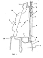
- eine Schnittdarstellung eines Ausschnitts aus dem Frontendbereich eines Kraftfahrzeugs,
- Fig. 2
- eine Schnittdarstellung eines Ausschnitts der erfin-dungsgemäßen Abstützvorrichtung,
- Fig. 2a
- eine Darstellung des Schnittes in der Ebene A-A aus
Figur 2 - Fig. 3
- eine perspektivische Darstellung eines Ausschnittes der erfindungsgemäßen Vorrichtung und
- Fig. 3a
- eine schematische Darstellung des Profils des Schnit-tes der Ebene A-A aus
Figur 3
- Fig. 1
- a sectional view of a section of the front end of a motor vehicle,
- Fig. 2
- a sectional view of a section of the inventive support device,
- Fig. 2a
- a representation of the section in the plane AA
FIG. 2 . - Fig. 3
- a perspective view of a section of the device according to the invention and
- Fig. 3a
- a schematic representation of the profile of the cut AA-level
FIG. 3 ,
In der
Durch das Eindrücken des Verstellbolzens 4 in das Aufnahmeelement 5 kommt die Auflagefläche 8 auf dem stützenden zweiten Bauteil 3 zur Anlage. Dieser Zustand ist bei der vorliegenden Darstellung mit unterbrochener Linie dargestellt. Ein Durchdrücken des Verstellelementes durch die Bohrung 9 des Aufnahmeelementes 5 wird dadurch verhindert, dass die Krone 21 des Verstellbolzens 4 einen größeren Durchmesser aufweist als die Bohrung 9 des Aufnahmeelementes 5. Die Fixierschraube 7 wird in dieser Position vollständig in das Verstellelement 4 eingedreht, was ebenfalls bei der
Im Folgenden soll nur noch kurz auf übrigen bei dieser Darstellung gezeigten Bauteile eingegangen werden, während die Funktionsweise der erfindungsgemäßen Vorrichtung an den nachfolgenden Figuren erläutert wird. So ist in dieser Darstellung darüber hinaus noch ein Chromrahmen 19 zu sehen, der als drittes Bauteil anzusehen ist, zu dem das erste abzustützende Bauteil 2 relativ ausgerichtet werden soll. Mit Hilfe der erfindungsgemäßen Abstützvorrichtung 1 gelingt es nun, ein Absetzen oder Absinken des ersten abzustützenden Bauteils 2, nämlich des Kühlerschutzgitters 18, auch bei Dauerbelastung relativ zu einem dritten Bauteil zu verhindern. Neben dem Chromrahmen 19 ist in der gewählten Darstellung noch eine Abdeckung 17 für den Stoßfängerquerträger 16 zu sehen, der als stützendes zweites Bauteil 3 fungiert.In the following, only a brief description will be made of other components shown in this diagram, while the mode of operation of the device according to the invention will be explained in the following figures. Thus, in this illustration, a
Die
Bei der Schnittdarstellung in der Ebene A-A, die in der
Die
Die Funktionsweise der Sicherung wird zusätzlich anhand eines Schnittes durch die Ebene A-A aus
Es soll darauf hingewiesen werden, dass die oben angeführten Beispiele ausschließlich zur Erklärung der Funktionsweise der Abstützvorrichtung gedacht sind und keinesfalls als Einschränkung zu sehen sind. So kann beispielsweise ein Durchdrücken des Verstellbolzens 4 auch dadurch verhindert werden, dass der Durchmesser des Schraubenkopfes größer ist als der Durchmesser der Bohrung 9.It should be noted that the examples given above are intended solely to explain the operation of the outrigger and are by no means to be construed as limiting. Thus, for example, a pressing of the adjusting
Weitere Varianten einzelner Details ergeben sich für den Fachmann aufgrund seines Fachwissens und sollen hier im Einzelnen nicht mehr aufgeführt werden.Other variants of individual details arise for the expert due to his expertise and should not be listed here in detail.
- 11
- AbstützvorrichtungSupport device
- 22
- Erstes BauteilFirst component
- 33
- Zweites BauteilSecond component
- 44
- Verstellelement (Verstellbolzen)Adjustment element (adjusting bolt)
- 55
- Aufnahmeelementreceiving element
- 66
- Bohrungdrilling
- 77
- Fixierelement (Fixierschraube)Fixing element (fixing screw)
- 88th
- Abstützflächesupporting
- 99
- Bohrungdrilling
- 1010
- Längsschlitzlongitudinal slot
- 1111
- Rastelementlocking element
- 1212
- Barrierebarrier
- 1313
- Entlastungsnutrelief
- 1414
- RasttascheRest case
- 1515
- Kühlergrillradiator grill
- 1616
- StoßfängerquerträgerBumper crossmember
- 1717
- Abdeckungcover
- 1818
- Kühlergrillradiator grill
- 1919
- Chromrahmenchrome frame
- 2020
- Schlüsselflächenkey areas
- 2121
- KroneCrown
Claims (12)
- An apparatus (1) for supporting a first component (2) on a second component (3) with automatic compensation of production and assembly tolerances between the two components (2, 3), wherein the apparatus (1) [comprises?] an adjustment element (4) having a bore (6) for receiving a fixing element (7) on a first, upper end and a support face (8) on a second, lower end as well as a receiving element (5) which has a continuous bore (9) and which receives the adjustment element (4),
wherein the adjustment element (4) is designed in the form of at least [one] adjustment pin (4) having a rotation prevention means, wherein the adjustment pin (4) has longitudinal slots (10) extending vertically and distributed symmetrically over the radius of the adjustment pin (4) in the region of the bore (6) for receiving the fixing element (7),
wherein the apparatus (1) is designed in the form of a separate component and is capable of being connected in a fixed manner by way of the receiving element (5) to the first component (2) to be supported, or the receiving element (5) is part of the first component (2) to be supported, characterized in that a conveying securing means, by which the loss of the adjustment pin (4) during the delivery of the component is prevented, is provided for the adjustment pin,
the adjustment pin (4) has a catch recess (14) into which a catch element (11) arranged on the receiving element (5) and provided as the conveying securing means engages in the delivery state, and
a relief groove (13), which is continuous as far as a crown (21) of the adjustment pin (4) and which extends vertically and by which the catch element (11) is received in the assembled state, is provided above the catch recess (14), wherein a ramp-shaped barrier (12) is provided between the catch recess (14) and the relief groove (13). - An apparatus according to claim 1, characterized in that the adjustment pin (4) has at least one flat key face (20) as the rotation prevention means.
- An apparatus according to one of claims 1 or 2, characterized in that the support face (8) of the adjustment element (4) is provided for support or abutment on the supporting second component (3).
- An apparatus according to any one of claims 1 to 3, characterized in that the ramp-shaped barrier (12) has a ramp angle of approximately 45°.
- An apparatus according to any one of claims 1 to 4, characterized in that a penetration prevention means is provided for the adjustment pin (4) in that the diameter of the crown (21) of the adjustment pin (4) or the diameter of the head of the fixing element (7) is greater than the internal diameter of the continuous bore (9) of the receiving element (5).
- An apparatus according to any one of claims 1 to 5, characterized in that both the receiving element (5) and the adjustment element (4) are produced from a thermoplastic plastics material.
- An apparatus according to any one of claims 1 to 6, characterized in that the fixing element (7) is designed in the form of a fixing screw (7).
- An apparatus according to claim 7, characterized in that the fixing screw (7) is a metallic screw with a thread appropriate for plastics materials or a metric thread, wherein the tip of the fixing screw (7) is designed without a thread in the form of a nail tip.
- An apparatus according to any one of claims 1 to 8, characterized in that the clamping between the support face (8) and the supporting component (3) is increased by suitable means.
- An apparatus according to any one of claims 1 to 9, characterized in that the first component (2) to be supported and the supporting second component (3) are in each case bodywork components for a motor vehicle.
- An apparatus according to claim 10, characterized in that the first component (2) to be supported is a radiator grille (15, 18) and the supporting second component (3) is a cross member of a bumper.
- An apparatus according to claim 8, characterized in that the first component (2) to be supported is a bumper combined with a radiator protection grille.
Priority Applications (2)
| Application Number | Priority Date | Filing Date | Title |
|---|---|---|---|
| EP20110004480 EP2530336B1 (en) | 2011-06-01 | 2011-06-01 | Device for supporting components |
| ES11004480.7T ES2486741T3 (en) | 2011-06-01 | 2011-06-01 | Device for supporting construction parts |
Applications Claiming Priority (1)
| Application Number | Priority Date | Filing Date | Title |
|---|---|---|---|
| EP20110004480 EP2530336B1 (en) | 2011-06-01 | 2011-06-01 | Device for supporting components |
Publications (2)
| Publication Number | Publication Date |
|---|---|
| EP2530336A1 EP2530336A1 (en) | 2012-12-05 |
| EP2530336B1 true EP2530336B1 (en) | 2014-06-25 |
Family
ID=44510632
Family Applications (1)
| Application Number | Title | Priority Date | Filing Date |
|---|---|---|---|
| EP20110004480 Active EP2530336B1 (en) | 2011-06-01 | 2011-06-01 | Device for supporting components |
Country Status (2)
| Country | Link |
|---|---|
| EP (1) | EP2530336B1 (en) |
| ES (1) | ES2486741T3 (en) |
Cited By (1)
| Publication number | Priority date | Publication date | Assignee | Title |
|---|---|---|---|---|
| DE202019106653U1 (en) * | 2019-11-29 | 2021-03-02 | Rehau Ag + Co | Carrier device for an outer paneling part of a motor vehicle |
Family Cites Families (14)
| Publication number | Priority date | Publication date | Assignee | Title |
|---|---|---|---|---|
| US3678798A (en) * | 1969-12-29 | 1972-07-25 | Eaton Corp | Fastening device |
| GB1477465A (en) * | 1974-09-25 | 1977-06-22 | Shelton W | Fastening devices |
| IT1134176B (en) * | 1980-11-05 | 1986-07-31 | Itw Fastex Italia Spa | ARRANGEMENT FOR CONNECTION OF AN AIR FILTER FOR VEHICLES TO THE RELATED CARBURETOR AND OF THE FILTER COVER TO THE SAME FILTER |
| US4898493A (en) * | 1989-03-16 | 1990-02-06 | Karl Blankenburg | Method and apparatus for assembling parts |
| FR2675219A1 (en) * | 1991-04-11 | 1992-10-16 | Moulinex Sa | FIXING DEVICE FOR RETAINING IN A POSITION DETERMINED A FIRST PIECE ON A SECOND PART. |
| US5178501A (en) * | 1991-10-29 | 1993-01-12 | Carstairs Arturo R | Axially adjustable screw anchor |
| FR2761127B1 (en) * | 1997-03-24 | 1999-06-04 | Itw De France | ARTICLE TO BE FIXED IN THE BLIND AND VEHICLE COMPRISING SAME |
| GB2344136A (en) * | 1998-11-27 | 2000-05-31 | Richco International Company L | Fastening device |
| DE102004050625A1 (en) | 2004-10-18 | 2006-04-27 | Audi Ag | Adjustment and attachment mechanism, has external thread and internal thread of screw unit in opposite direction, where torque higher than that for rotation of retaining screw, is required for rotation of screw unit |
| DE102005044064A1 (en) | 2005-09-15 | 2007-03-22 | GM Global Technology Operations, Inc., Detroit | Screw connection with tolerance compensation |
| FR2896020A1 (en) * | 2006-01-06 | 2007-07-13 | Ind De Moules Et Moulages Plas | Fixing with adjuster for attaching a component such as a frame to a support has insert made from fixed and movable elements with threaded surfaces |
| DE102006040759B3 (en) | 2006-08-31 | 2008-02-07 | Bayerische Motoren Werke Ag | Tolerance compensating arrangement, has compensating bushing with flange at end, and bushing resting on component in assembled condition, where bushing has inner diameter smaller than outer thread of screw |
| CN102597541A (en) * | 2009-10-29 | 2012-07-18 | 八千代工业株式会社 | Component mounting structure and push nut |
| DE202010003368U1 (en) | 2010-03-09 | 2010-06-02 | Peguform Gmbh | Device with selbstätigem compensation of manufacturing or assembly-related tolerances for supporting a first component to a second component |
-
2011
- 2011-06-01 ES ES11004480.7T patent/ES2486741T3/en active Active
- 2011-06-01 EP EP20110004480 patent/EP2530336B1/en active Active
Cited By (2)
| Publication number | Priority date | Publication date | Assignee | Title |
|---|---|---|---|---|
| DE202019106653U1 (en) * | 2019-11-29 | 2021-03-02 | Rehau Ag + Co | Carrier device for an outer paneling part of a motor vehicle |
| EP3828039A1 (en) | 2019-11-29 | 2021-06-02 | REHAU AG + Co | Support device for an external cladding section of a motor vehicle |
Also Published As
| Publication number | Publication date |
|---|---|
| EP2530336A1 (en) | 2012-12-05 |
| ES2486741T3 (en) | 2014-08-19 |
Similar Documents
| Publication | Publication Date | Title |
|---|---|---|
| DE102008015579B4 (en) | Stop arrangement and method for setting up a stop for two mutually movable components | |
| DE69909218T2 (en) | DOOR STOP FALL | |
| DE102006012176A1 (en) | Adjustable window lift I | |
| EP2804786A1 (en) | Roof rail for a motor vehicle | |
| DE102006061611A1 (en) | Bumper stop for back door of motor vehicle, has case moved with bolts with its cap over its rod running in axial direction, within recesses penetrated by flange in its withdrawn position, and moved into end position of flange | |
| DE10354117A1 (en) | Tolerance compensation element | |
| EP3742932A1 (en) | Front panel for a drawer | |
| EP2504511B1 (en) | Strap part of a strap hinge | |
| DE102017004342B3 (en) | Hinge for a vehicle flap | |
| DE202007003675U1 (en) | Device for fastening fittings to hollow sections | |
| DE202006010207U1 (en) | Device for attachment to a profile | |
| DE102014113126A1 (en) | TOLERANCE COMPENSATION DEVICE | |
| EP2530336B1 (en) | Device for supporting components | |
| EP2369184A2 (en) | Device with self-actuated compensation of production or installation-related tolerances for resting one component on a second component | |
| DE102013010490B4 (en) | Front of a motor vehicle | |
| DE102011002031A1 (en) | Anchoring device for fastening a component to a carrier element | |
| DE102013112846A1 (en) | Arrangement for fastening a first body part to a second body part of a motor vehicle | |
| DE10349878B4 (en) | Fastening device to a vehicle body and corresponding vehicle body | |
| DE102012000827B4 (en) | Roof rails for a motor vehicle and method for attaching a roof rail cover | |
| DE102004050540A1 (en) | Attachment arrangement for fitting cladding part, especially to essentially vertical surface, has locking arrangements on opposite sides of base that interact with attachment arrangements in surface, cladding part attachment arrangement | |
| EP3029241A1 (en) | Corner fitting with increased clamping force | |
| DE102020125085B4 (en) | Pre-assembled assembly for use in connecting two components and method for producing a pre-assembled assembly | |
| EP0984173A2 (en) | Element for positioning and fastening two structural elements at a distance and connection using same | |
| DE10231099A1 (en) | Plastic wing attachment system for motor vehicle has elongated hole in wing in which joint bush is inserted | |
| DE10035569B4 (en) | Fitting part for a window, a door or the like |
Legal Events
| Date | Code | Title | Description |
|---|---|---|---|
| PUAI | Public reference made under article 153(3) epc to a published international application that has entered the european phase |
Free format text: ORIGINAL CODE: 0009012 |
|
| AK | Designated contracting states |
Kind code of ref document: A1 Designated state(s): AL AT BE BG CH CY CZ DE DK EE ES FI FR GB GR HR HU IE IS IT LI LT LU LV MC MK MT NL NO PL PT RO RS SE SI SK SM TR |
|
| AX | Request for extension of the european patent |
Extension state: BA ME |
|
| 17P | Request for examination filed |
Effective date: 20130523 |
|
| RBV | Designated contracting states (corrected) |
Designated state(s): AL AT BE BG CH CY CZ DE DK EE ES FI FR GB GR HR HU IE IS IT LI LT LU LV MC MK MT NL NO PL PT RO RS SE SI SK SM TR |
|
| RIC1 | Information provided on ipc code assigned before grant |
Ipc: F16B 5/02 20060101AFI20131206BHEP |
|
| GRAP | Despatch of communication of intention to grant a patent |
Free format text: ORIGINAL CODE: EPIDOSNIGR1 |
|
| INTG | Intention to grant announced |
Effective date: 20140117 |
|
| GRAS | Grant fee paid |
Free format text: ORIGINAL CODE: EPIDOSNIGR3 |
|
| GRAA | (expected) grant |
Free format text: ORIGINAL CODE: 0009210 |
|
| AK | Designated contracting states |
Kind code of ref document: B1 Designated state(s): AL AT BE BG CH CY CZ DE DK EE ES FI FR GB GR HR HU IE IS IT LI LT LU LV MC MK MT NL NO PL PT RO RS SE SI SK SM TR |
|
| REG | Reference to a national code |
Ref country code: GB Ref legal event code: FG4D Free format text: NOT ENGLISH |
|
| RIN1 | Information on inventor provided before grant (corrected) |
Inventor name: GUT, DIETER Inventor name: OTTO, PETER Inventor name: HANSCHICK, HEINZ Inventor name: STEININGER, JOHANNES Inventor name: VOLLET, HEINZ Inventor name: WERNER, MARTIN |
|
| REG | Reference to a national code |
Ref country code: CH Ref legal event code: EP |
|
| REG | Reference to a national code |
Ref country code: AT Ref legal event code: REF Ref document number: 674895 Country of ref document: AT Kind code of ref document: T Effective date: 20140715 |
|
| REG | Reference to a national code |
Ref country code: IE Ref legal event code: FG4D Free format text: LANGUAGE OF EP DOCUMENT: GERMAN |
|
| REG | Reference to a national code |
Ref country code: DE Ref legal event code: R096 Ref document number: 502011003501 Country of ref document: DE Effective date: 20140807 |
|
| REG | Reference to a national code |
Ref country code: ES Ref legal event code: FG2A Ref document number: 2486741 Country of ref document: ES Kind code of ref document: T3 Effective date: 20140819 |
|
| PG25 | Lapsed in a contracting state [announced via postgrant information from national office to epo] |
Ref country code: LT Free format text: LAPSE BECAUSE OF FAILURE TO SUBMIT A TRANSLATION OF THE DESCRIPTION OR TO PAY THE FEE WITHIN THE PRESCRIBED TIME-LIMIT Effective date: 20140625 Ref country code: NO Free format text: LAPSE BECAUSE OF FAILURE TO SUBMIT A TRANSLATION OF THE DESCRIPTION OR TO PAY THE FEE WITHIN THE PRESCRIBED TIME-LIMIT Effective date: 20140925 Ref country code: FI Free format text: LAPSE BECAUSE OF FAILURE TO SUBMIT A TRANSLATION OF THE DESCRIPTION OR TO PAY THE FEE WITHIN THE PRESCRIBED TIME-LIMIT Effective date: 20140625 Ref country code: GR Free format text: LAPSE BECAUSE OF FAILURE TO SUBMIT A TRANSLATION OF THE DESCRIPTION OR TO PAY THE FEE WITHIN THE PRESCRIBED TIME-LIMIT Effective date: 20140926 Ref country code: CY Free format text: LAPSE BECAUSE OF FAILURE TO SUBMIT A TRANSLATION OF THE DESCRIPTION OR TO PAY THE FEE WITHIN THE PRESCRIBED TIME-LIMIT Effective date: 20140625 |
|
| REG | Reference to a national code |
Ref country code: NL Ref legal event code: VDEP Effective date: 20140625 |
|
| REG | Reference to a national code |
Ref country code: LT Ref legal event code: MG4D |
|
| PG25 | Lapsed in a contracting state [announced via postgrant information from national office to epo] |
Ref country code: HR Free format text: LAPSE BECAUSE OF FAILURE TO SUBMIT A TRANSLATION OF THE DESCRIPTION OR TO PAY THE FEE WITHIN THE PRESCRIBED TIME-LIMIT Effective date: 20140625 Ref country code: SE Free format text: LAPSE BECAUSE OF FAILURE TO SUBMIT A TRANSLATION OF THE DESCRIPTION OR TO PAY THE FEE WITHIN THE PRESCRIBED TIME-LIMIT Effective date: 20140625 Ref country code: LV Free format text: LAPSE BECAUSE OF FAILURE TO SUBMIT A TRANSLATION OF THE DESCRIPTION OR TO PAY THE FEE WITHIN THE PRESCRIBED TIME-LIMIT Effective date: 20140625 Ref country code: RS Free format text: LAPSE BECAUSE OF FAILURE TO SUBMIT A TRANSLATION OF THE DESCRIPTION OR TO PAY THE FEE WITHIN THE PRESCRIBED TIME-LIMIT Effective date: 20140625 |
|
| PG25 | Lapsed in a contracting state [announced via postgrant information from national office to epo] |
Ref country code: RO Free format text: LAPSE BECAUSE OF FAILURE TO SUBMIT A TRANSLATION OF THE DESCRIPTION OR TO PAY THE FEE WITHIN THE PRESCRIBED TIME-LIMIT Effective date: 20140625 Ref country code: EE Free format text: LAPSE BECAUSE OF FAILURE TO SUBMIT A TRANSLATION OF THE DESCRIPTION OR TO PAY THE FEE WITHIN THE PRESCRIBED TIME-LIMIT Effective date: 20140625 Ref country code: PT Free format text: LAPSE BECAUSE OF FAILURE TO SUBMIT A TRANSLATION OF THE DESCRIPTION OR TO PAY THE FEE WITHIN THE PRESCRIBED TIME-LIMIT Effective date: 20141027 Ref country code: SK Free format text: LAPSE BECAUSE OF FAILURE TO SUBMIT A TRANSLATION OF THE DESCRIPTION OR TO PAY THE FEE WITHIN THE PRESCRIBED TIME-LIMIT Effective date: 20140625 |
|
| PG25 | Lapsed in a contracting state [announced via postgrant information from national office to epo] |
Ref country code: NL Free format text: LAPSE BECAUSE OF FAILURE TO SUBMIT A TRANSLATION OF THE DESCRIPTION OR TO PAY THE FEE WITHIN THE PRESCRIBED TIME-LIMIT Effective date: 20140625 Ref country code: PL Free format text: LAPSE BECAUSE OF FAILURE TO SUBMIT A TRANSLATION OF THE DESCRIPTION OR TO PAY THE FEE WITHIN THE PRESCRIBED TIME-LIMIT Effective date: 20140625 Ref country code: IS Free format text: LAPSE BECAUSE OF FAILURE TO SUBMIT A TRANSLATION OF THE DESCRIPTION OR TO PAY THE FEE WITHIN THE PRESCRIBED TIME-LIMIT Effective date: 20141025 |
|
| REG | Reference to a national code |
Ref country code: DE Ref legal event code: R097 Ref document number: 502011003501 Country of ref document: DE |
|
| PG25 | Lapsed in a contracting state [announced via postgrant information from national office to epo] |
Ref country code: DK Free format text: LAPSE BECAUSE OF FAILURE TO SUBMIT A TRANSLATION OF THE DESCRIPTION OR TO PAY THE FEE WITHIN THE PRESCRIBED TIME-LIMIT Effective date: 20140625 |
|
| PLBE | No opposition filed within time limit |
Free format text: ORIGINAL CODE: 0009261 |
|
| STAA | Information on the status of an ep patent application or granted ep patent |
Free format text: STATUS: NO OPPOSITION FILED WITHIN TIME LIMIT |
|
| 26N | No opposition filed |
Effective date: 20150326 |
|
| PG25 | Lapsed in a contracting state [announced via postgrant information from national office to epo] |
Ref country code: SI Free format text: LAPSE BECAUSE OF FAILURE TO SUBMIT A TRANSLATION OF THE DESCRIPTION OR TO PAY THE FEE WITHIN THE PRESCRIBED TIME-LIMIT Effective date: 20140625 |
|
| PG25 | Lapsed in a contracting state [announced via postgrant information from national office to epo] |
Ref country code: MC Free format text: LAPSE BECAUSE OF FAILURE TO SUBMIT A TRANSLATION OF THE DESCRIPTION OR TO PAY THE FEE WITHIN THE PRESCRIBED TIME-LIMIT Effective date: 20140625 |
|
| REG | Reference to a national code |
Ref country code: CH Ref legal event code: PL |
|
| PG25 | Lapsed in a contracting state [announced via postgrant information from national office to epo] |
Ref country code: LU Free format text: LAPSE BECAUSE OF FAILURE TO SUBMIT A TRANSLATION OF THE DESCRIPTION OR TO PAY THE FEE WITHIN THE PRESCRIBED TIME-LIMIT Effective date: 20150601 |
|
| REG | Reference to a national code |
Ref country code: IE Ref legal event code: MM4A |
|
| PG25 | Lapsed in a contracting state [announced via postgrant information from national office to epo] |
Ref country code: CH Free format text: LAPSE BECAUSE OF NON-PAYMENT OF DUE FEES Effective date: 20150630 Ref country code: LI Free format text: LAPSE BECAUSE OF NON-PAYMENT OF DUE FEES Effective date: 20150630 Ref country code: IE Free format text: LAPSE BECAUSE OF NON-PAYMENT OF DUE FEES Effective date: 20150601 |
|
| REG | Reference to a national code |
Ref country code: FR Ref legal event code: PLFP Year of fee payment: 6 |
|
| PG25 | Lapsed in a contracting state [announced via postgrant information from national office to epo] |
Ref country code: MT Free format text: LAPSE BECAUSE OF FAILURE TO SUBMIT A TRANSLATION OF THE DESCRIPTION OR TO PAY THE FEE WITHIN THE PRESCRIBED TIME-LIMIT Effective date: 20140625 |
|
| PG25 | Lapsed in a contracting state [announced via postgrant information from national office to epo] |
Ref country code: HU Free format text: LAPSE BECAUSE OF FAILURE TO SUBMIT A TRANSLATION OF THE DESCRIPTION OR TO PAY THE FEE WITHIN THE PRESCRIBED TIME-LIMIT; INVALID AB INITIO Effective date: 20110601 |
|
| REG | Reference to a national code |
Ref country code: FR Ref legal event code: PLFP Year of fee payment: 7 |
|
| PG25 | Lapsed in a contracting state [announced via postgrant information from national office to epo] |
Ref country code: BG Free format text: LAPSE BECAUSE OF THE APPLICANT RENOUNCES Effective date: 20150630 |
|
| PG25 | Lapsed in a contracting state [announced via postgrant information from national office to epo] |
Ref country code: BE Free format text: LAPSE BECAUSE OF NON-PAYMENT OF DUE FEES Effective date: 20150630 Ref country code: SM Free format text: LAPSE BECAUSE OF FAILURE TO SUBMIT A TRANSLATION OF THE DESCRIPTION OR TO PAY THE FEE WITHIN THE PRESCRIBED TIME-LIMIT Effective date: 20140625 |
|
| REG | Reference to a national code |
Ref country code: AT Ref legal event code: MM01 Ref document number: 674895 Country of ref document: AT Kind code of ref document: T Effective date: 20160601 |
|
| PG25 | Lapsed in a contracting state [announced via postgrant information from national office to epo] |
Ref country code: TR Free format text: LAPSE BECAUSE OF FAILURE TO SUBMIT A TRANSLATION OF THE DESCRIPTION OR TO PAY THE FEE WITHIN THE PRESCRIBED TIME-LIMIT Effective date: 20140625 |
|
| PG25 | Lapsed in a contracting state [announced via postgrant information from national office to epo] |
Ref country code: AT Free format text: LAPSE BECAUSE OF NON-PAYMENT OF DUE FEES Effective date: 20160601 |
|
| REG | Reference to a national code |
Ref country code: FR Ref legal event code: PLFP Year of fee payment: 8 |
|
| PG25 | Lapsed in a contracting state [announced via postgrant information from national office to epo] |
Ref country code: MK Free format text: LAPSE BECAUSE OF FAILURE TO SUBMIT A TRANSLATION OF THE DESCRIPTION OR TO PAY THE FEE WITHIN THE PRESCRIBED TIME-LIMIT Effective date: 20140625 |
|
| PG25 | Lapsed in a contracting state [announced via postgrant information from national office to epo] |
Ref country code: AL Free format text: LAPSE BECAUSE OF FAILURE TO SUBMIT A TRANSLATION OF THE DESCRIPTION OR TO PAY THE FEE WITHIN THE PRESCRIBED TIME-LIMIT Effective date: 20140625 |
|
| P01 | Opt-out of the competence of the unified patent court (upc) registered |
Effective date: 20230427 |
|
| PGFP | Annual fee paid to national office [announced via postgrant information from national office to epo] |
Ref country code: FR Payment date: 20230620 Year of fee payment: 13 Ref country code: DE Payment date: 20230620 Year of fee payment: 13 Ref country code: CZ Payment date: 20230519 Year of fee payment: 13 |
|
| PGFP | Annual fee paid to national office [announced via postgrant information from national office to epo] |
Ref country code: IT Payment date: 20230630 Year of fee payment: 13 Ref country code: GB Payment date: 20230622 Year of fee payment: 13 Ref country code: ES Payment date: 20230719 Year of fee payment: 13 |