EP2590837B1 - Ladegerät für elektrofahrzeuge - Google Patents
Ladegerät für elektrofahrzeuge Download PDFInfo
- Publication number
- EP2590837B1 EP2590837B1 EP11767754.2A EP11767754A EP2590837B1 EP 2590837 B1 EP2590837 B1 EP 2590837B1 EP 11767754 A EP11767754 A EP 11767754A EP 2590837 B1 EP2590837 B1 EP 2590837B1
- Authority
- EP
- European Patent Office
- Prior art keywords
- charging
- power supply
- current
- voltage
- control
- Prior art date
- Legal status (The legal status is an assumption and is not a legal conclusion. Google has not performed a legal analysis and makes no representation as to the accuracy of the status listed.)
- Active
Links
Images


Classifications
-
- B—PERFORMING OPERATIONS; TRANSPORTING
- B60—VEHICLES IN GENERAL
- B60L—PROPULSION OF ELECTRICALLY-PROPELLED VEHICLES; SUPPLYING ELECTRIC POWER FOR AUXILIARY EQUIPMENT OF ELECTRICALLY-PROPELLED VEHICLES; ELECTRODYNAMIC BRAKE SYSTEMS FOR VEHICLES IN GENERAL; MAGNETIC SUSPENSION OR LEVITATION FOR VEHICLES; MONITORING OPERATING VARIABLES OF ELECTRICALLY-PROPELLED VEHICLES; ELECTRIC SAFETY DEVICES FOR ELECTRICALLY-PROPELLED VEHICLES
- B60L53/00—Methods of charging batteries, specially adapted for electric vehicles; Charging stations or on-board charging equipment therefor; Exchange of energy storage elements in electric vehicles
- B60L53/20—Methods of charging batteries, specially adapted for electric vehicles; Charging stations or on-board charging equipment therefor; Exchange of energy storage elements in electric vehicles characterised by converters located in the vehicle
-
- H—ELECTRICITY
- H02—GENERATION; CONVERSION OR DISTRIBUTION OF ELECTRIC POWER
- H02J—CIRCUIT ARRANGEMENTS OR SYSTEMS FOR SUPPLYING OR DISTRIBUTING ELECTRIC POWER; SYSTEMS FOR STORING ELECTRIC ENERGY
- H02J7/00—Circuit arrangements for charging or depolarising batteries or for supplying loads from batteries
- H02J7/02—Circuit arrangements for charging or depolarising batteries or for supplying loads from batteries for charging batteries from AC mains by converters
- H02J7/04—Regulation of charging current or voltage
-
- H—ELECTRICITY
- H02—GENERATION; CONVERSION OR DISTRIBUTION OF ELECTRIC POWER
- H02M—APPARATUS FOR CONVERSION BETWEEN AC AND AC, BETWEEN AC AND DC, OR BETWEEN DC AND DC, AND FOR USE WITH MAINS OR SIMILAR POWER SUPPLY SYSTEMS; CONVERSION OF DC OR AC INPUT POWER INTO SURGE OUTPUT POWER; CONTROL OR REGULATION THEREOF
- H02M3/00—Conversion of DC power input into DC power output
- H02M3/02—Conversion of DC power input into DC power output without intermediate conversion into AC
- H02M3/04—Conversion of DC power input into DC power output without intermediate conversion into AC by static converters
- H02M3/10—Conversion of DC power input into DC power output without intermediate conversion into AC by static converters using discharge tubes with control electrode or semiconductor devices with control electrode
- H02M3/145—Conversion of DC power input into DC power output without intermediate conversion into AC by static converters using discharge tubes with control electrode or semiconductor devices with control electrode using devices of a triode or transistor type requiring continuous application of a control signal
- H02M3/155—Conversion of DC power input into DC power output without intermediate conversion into AC by static converters using discharge tubes with control electrode or semiconductor devices with control electrode using devices of a triode or transistor type requiring continuous application of a control signal using semiconductor devices only
-
- B—PERFORMING OPERATIONS; TRANSPORTING
- B60—VEHICLES IN GENERAL
- B60L—PROPULSION OF ELECTRICALLY-PROPELLED VEHICLES; SUPPLYING ELECTRIC POWER FOR AUXILIARY EQUIPMENT OF ELECTRICALLY-PROPELLED VEHICLES; ELECTRODYNAMIC BRAKE SYSTEMS FOR VEHICLES IN GENERAL; MAGNETIC SUSPENSION OR LEVITATION FOR VEHICLES; MONITORING OPERATING VARIABLES OF ELECTRICALLY-PROPELLED VEHICLES; ELECTRIC SAFETY DEVICES FOR ELECTRICALLY-PROPELLED VEHICLES
- B60L2210/00—Converter types
- B60L2210/10—DC to DC converters
-
- B—PERFORMING OPERATIONS; TRANSPORTING
- B60—VEHICLES IN GENERAL
- B60L—PROPULSION OF ELECTRICALLY-PROPELLED VEHICLES; SUPPLYING ELECTRIC POWER FOR AUXILIARY EQUIPMENT OF ELECTRICALLY-PROPELLED VEHICLES; ELECTRODYNAMIC BRAKE SYSTEMS FOR VEHICLES IN GENERAL; MAGNETIC SUSPENSION OR LEVITATION FOR VEHICLES; MONITORING OPERATING VARIABLES OF ELECTRICALLY-PROPELLED VEHICLES; ELECTRIC SAFETY DEVICES FOR ELECTRICALLY-PROPELLED VEHICLES
- B60L2210/00—Converter types
- B60L2210/30—AC to DC converters
-
- Y—GENERAL TAGGING OF NEW TECHNOLOGICAL DEVELOPMENTS; GENERAL TAGGING OF CROSS-SECTIONAL TECHNOLOGIES SPANNING OVER SEVERAL SECTIONS OF THE IPC; TECHNICAL SUBJECTS COVERED BY FORMER USPC CROSS-REFERENCE ART COLLECTIONS [XRACs] AND DIGESTS
- Y02—TECHNOLOGIES OR APPLICATIONS FOR MITIGATION OR ADAPTATION AGAINST CLIMATE CHANGE
- Y02T—CLIMATE CHANGE MITIGATION TECHNOLOGIES RELATED TO TRANSPORTATION
- Y02T10/00—Road transport of goods or passengers
- Y02T10/60—Other road transportation technologies with climate change mitigation effect
- Y02T10/70—Energy storage systems for electromobility, e.g. batteries
-
- Y—GENERAL TAGGING OF NEW TECHNOLOGICAL DEVELOPMENTS; GENERAL TAGGING OF CROSS-SECTIONAL TECHNOLOGIES SPANNING OVER SEVERAL SECTIONS OF THE IPC; TECHNICAL SUBJECTS COVERED BY FORMER USPC CROSS-REFERENCE ART COLLECTIONS [XRACs] AND DIGESTS
- Y02—TECHNOLOGIES OR APPLICATIONS FOR MITIGATION OR ADAPTATION AGAINST CLIMATE CHANGE
- Y02T—CLIMATE CHANGE MITIGATION TECHNOLOGIES RELATED TO TRANSPORTATION
- Y02T10/00—Road transport of goods or passengers
- Y02T10/60—Other road transportation technologies with climate change mitigation effect
- Y02T10/7072—Electromobility specific charging systems or methods for batteries, ultracapacitors, supercapacitors or double-layer capacitors
-
- Y—GENERAL TAGGING OF NEW TECHNOLOGICAL DEVELOPMENTS; GENERAL TAGGING OF CROSS-SECTIONAL TECHNOLOGIES SPANNING OVER SEVERAL SECTIONS OF THE IPC; TECHNICAL SUBJECTS COVERED BY FORMER USPC CROSS-REFERENCE ART COLLECTIONS [XRACs] AND DIGESTS
- Y02—TECHNOLOGIES OR APPLICATIONS FOR MITIGATION OR ADAPTATION AGAINST CLIMATE CHANGE
- Y02T—CLIMATE CHANGE MITIGATION TECHNOLOGIES RELATED TO TRANSPORTATION
- Y02T10/00—Road transport of goods or passengers
- Y02T10/60—Other road transportation technologies with climate change mitigation effect
- Y02T10/72—Electric energy management in electromobility
-
- Y—GENERAL TAGGING OF NEW TECHNOLOGICAL DEVELOPMENTS; GENERAL TAGGING OF CROSS-SECTIONAL TECHNOLOGIES SPANNING OVER SEVERAL SECTIONS OF THE IPC; TECHNICAL SUBJECTS COVERED BY FORMER USPC CROSS-REFERENCE ART COLLECTIONS [XRACs] AND DIGESTS
- Y02—TECHNOLOGIES OR APPLICATIONS FOR MITIGATION OR ADAPTATION AGAINST CLIMATE CHANGE
- Y02T—CLIMATE CHANGE MITIGATION TECHNOLOGIES RELATED TO TRANSPORTATION
- Y02T10/00—Road transport of goods or passengers
- Y02T10/80—Technologies aiming to reduce greenhouse gasses emissions common to all road transportation technologies
- Y02T10/92—Energy efficient charging or discharging systems for batteries, ultracapacitors, supercapacitors or double-layer capacitors specially adapted for vehicles
-
- Y—GENERAL TAGGING OF NEW TECHNOLOGICAL DEVELOPMENTS; GENERAL TAGGING OF CROSS-SECTIONAL TECHNOLOGIES SPANNING OVER SEVERAL SECTIONS OF THE IPC; TECHNICAL SUBJECTS COVERED BY FORMER USPC CROSS-REFERENCE ART COLLECTIONS [XRACs] AND DIGESTS
- Y02—TECHNOLOGIES OR APPLICATIONS FOR MITIGATION OR ADAPTATION AGAINST CLIMATE CHANGE
- Y02T—CLIMATE CHANGE MITIGATION TECHNOLOGIES RELATED TO TRANSPORTATION
- Y02T90/00—Enabling technologies or technologies with a potential or indirect contribution to GHG emissions mitigation
- Y02T90/10—Technologies relating to charging of electric vehicles
- Y02T90/12—Electric charging stations
-
- Y—GENERAL TAGGING OF NEW TECHNOLOGICAL DEVELOPMENTS; GENERAL TAGGING OF CROSS-SECTIONAL TECHNOLOGIES SPANNING OVER SEVERAL SECTIONS OF THE IPC; TECHNICAL SUBJECTS COVERED BY FORMER USPC CROSS-REFERENCE ART COLLECTIONS [XRACs] AND DIGESTS
- Y02—TECHNOLOGIES OR APPLICATIONS FOR MITIGATION OR ADAPTATION AGAINST CLIMATE CHANGE
- Y02T—CLIMATE CHANGE MITIGATION TECHNOLOGIES RELATED TO TRANSPORTATION
- Y02T90/00—Enabling technologies or technologies with a potential or indirect contribution to GHG emissions mitigation
- Y02T90/10—Technologies relating to charging of electric vehicles
- Y02T90/14—Plug-in electric vehicles
Definitions
- the invention relates to a charging device for an electromotive vehicle and, more particularly, to charging control for charging an electrical storage device, equipped for an electromotive vehicle, by a power supply outside the vehicle.
- An electric vehicle, a hybrid vehicle, a fuel cell vehicle, and the like, are known as electromotive vehicles that are configured to be able to generate vehicle driving force using electric power from an in-vehicle electrical storage device, typically, a secondary battery.
- an electromotive vehicle that is configured to charge an in-vehicle electrical storage device by a power supply outside the vehicle (hereinafter, also simply referred to as “external power supply”).
- charging the electrical storage device by the external power supply is also simply referred to as “external charging”.
- JP-A-2007-318970 describes that a charging device that converts electric power, supplied from an external power supply, to electric power for charging an electrical storage device is formed of two alternating-current motors equipped for a hybrid vehicle and inverters and step-up converter for driving these alternating-current motors.
- the charging device described in JP-A-2007-318970 is configured to receive electric power from the external power supply via respective neutral points of the two alternating-current motors.
- JP-2009033785 A or EP 2 178 189 A1 describes charging control in a power supply system of an electromotive vehicle, in which a plurality of pairs of electrical storage device and converter are arranged in parallel with each other.
- JP-A-2009-33785 describes control for charging each electrical storage device by keeping an upper arm element of a corresponding step-up chopper DC-DC converter circuit (converter) in an on state.
- JP-A-2009-33785 describes that the electrical storage device is charged with the increased efficiency of each chopper DC-DC converter circuit in such a manner that the upper arm element of any one of the DC-DC converter circuits is kept in an on state, but JP-A-2009-33785 does not specifically describe under what condition such charging control should be applied. However, depending on the state of external charging, when the upper arm element of any one of the DC-DC converter circuits is kept in an on state, there may occur a case where efficiency in elements other than the DC-DC converter circuit decreases or a case where excessive current occurs.
- the invention provides an electrical storage device that is equipped for an electromotive vehicle and that may be charged with electric power from an external power supply with high efficiency.
- An aspect of the invention relates to a charging device for an electromotive vehicle equipped with an electrical storage device.
- the charging device includes a first electric power converter, a second electric power converter, and a control device that is used to control the first and second electric power converters.
- the first electric power converter converts an alternating-current voltage, supplied from an external power supply, to a direct-current voltage higher than a peak voltage of the alternating-current voltage, and outputs the direct-current voltage to a first power supply line.
- the second electric power converter during external charging for charging the electrical storage device by the external power supply, is used to convert a direct-current electric power between the first power supply line and a second power supply line that is electrically connected to a positive electrode of the electrical storage device.
- the second electric power converter includes a first switching element that is electrically connected between a first node and the first power supply line and a first inductor that is electrically connected between the first node and the second power supply line.
- the control device selects any one of a first control mode in which the electrical storage device is charged through on/off control over the first switching element and a second control mode in which the electrical storage device is charged while the first switching element is kept in an on state, on the basis of a state of the external charging.
- the control device may select the second control mode when a voltage of the electrical storage device is higher than the peak voltage of the alternating-current voltage.
- control device may select the second control mode when a charging electric power for charging the electrical storage device is lower than a predetermined level.
- the first electric power converter may include a rectifier, a second inductor, a first diode and a second switching element.
- the rectifier may rectify the alternating-current voltage supplied from the external power supply and then output the rectified voltage to a third power supply line.
- the second inductor may be electrically connected between the third power supply line and a second node.
- the first diode may be electrically connected between the second node and the first power supply line so that a direction from the second node to the first power supply line is set as a forward direction.
- the second switching element may be electrically connected between the second node and a fourth power supply line that is electrically connected to a negative electrode of the electrical storage device.
- the control device may control on/off states of the second switching element so that a current that passes through the second inductor coincides with a target current.
- the target current is an absolute value of an alternating current of which a phase coincides with a phase of the alternating-current voltage.
- the control device may control an amplitude of the target current on the basis of a voltage of the first power supply line in the first control mode, and may keep the amplitude of the target current constant irrespective of the voltage of the first power supply line in the second control mode.
- control device may control a duty ratio of on/off states of the first switching element on the basis of a difference between a charging current for charging the electrical storage device and a target charging current.
- the control device may change from the first control mode to the second control mode after a voltage of the first power supply line has decreased to a voltage of the electrical storage device.
- the control device may stop the first and second electric power converters and decrease the voltage of the first power supply line by discharging using a discharging resistor.
- the control device may decrease a target voltage of the voltage of the first power supply line, supplied to the second electric power converter, to the voltage of the electrical storage device.
- FIG. 1 is a circuit diagram for illustrating a configuration example of a charging device for an electromotive vehicle according to the embodiment of the invention.
- an electromotive vehicle 100 includes a main battery 10, a current sensor 12, a battery sensor 15, a battery monitoring unit 20, a system main relay 30, a DC-DC converter 40, an auxiliary battery 45 and a driving device 50. As described above, the electromotive vehicle 100 is configured to be able to generate vehicle driving force using electric power from the main battery 10.
- the electromotive vehicle 100 includes an electric vehicle, a hybrid vehicle and a fuel cell vehicle.
- the main battery 10 is illustrated as a typical example of an "electrical storage device".
- the main battery 10 is typically formed of a secondary battery, such as a lithium ion battery and a nickel metal hydride battery.
- the output voltage of the main battery 10 is about 200 V.
- the "electrical storage device” may be, for example, formed of an electric double layer capacitor or may be formed of a combination of a secondary battery and a capacitor.
- the current sensor 12 detects the output current (hereinafter, also referred to as battery current) IB of the main battery 10, and transmits the detected battery current IB to the battery monitoring unit 20.
- the battery current IB during charging is indicated by positive value.
- the battery sensor 15 is attached to the main battery 10, and detects a battery voltage VB and a battery temperature TB. The battery voltage VB and the battery temperature TB detected by the battery sensor 15 are transmitted to the battery monitoring unit 20.
- the battery monitoring unit 20 monitors the state of the main battery 10 on the basis of the battery current IB, the battery voltage VB and the battery temperature TB. Typically, the battery monitoring unit 20 calculates a state of charge (SOC) that is indicated by the ratio (0 to 100%) of a current amount of charge to a full charge capacity in the main battery 10. In addition, the battery monitoring unit 20 sets the charging electric power upper limit value and discharging electric power upper limit value of the main battery 10 on the basis of the state of the main battery 10.
- SOC state of charge
- the driving device 50 includes a motor generator (MG) (not shown) and an electric power converter (inverter/converter) (not shown).
- the motor generator (MG) is used to generate vehicle driving force using electric power from the main battery 10.
- the electric power converter (inverter/converter) is used to drive the motor generator.
- the motor generator (MG) operates as a generator that converts deceleration energy to electric energy during regenerative braking of the electromotive vehicle 100. Regenerated electric power is converted to electric power for charging the main battery 10 by the electric power converter (inverter/converter).
- the system main relay 30 is connected in a current-carrying path between the main battery 10 and the driving device 50.
- the system main relay 30 is basically turned on while the vehicle is traveling; whereas the system main relay 30 is turned off during external charging. However, during external charging, when it is required to operate an auxiliary system, the system main relay 30 may be turned on through user's operation, or the like.
- the DC-DC converter 40 is connected to the system main relay 30 in parallel with the driving device 50.
- the DC-DC converter 40 steps down the output voltage of the main battery 10 to the power supply voltage of the auxiliary system (for example, about 12 V).
- the DC-DC converter 40 is typically a switching regulator that includes semiconductor switching elements (not shown). A selected known circuit configuration may be applied to the DC-DC converter 40.
- the auxiliary battery 45 is charged with the output voltage of the DC-DC converter 40.
- An auxiliary load (not shown) is connected to the auxiliary battery 45.
- the auxiliary load includes an audio device, compact motors, an electronic control unit (ECU), and the like, that operate on electric power supplied from the auxiliary battery 45.
- the system main relay 30 When the system main relay 30 is turned on, the electric power of the main battery 10 is supplied to the driving device 50 and the DC-DC converter 40. On the other hand, when the system main relay 30 is turned off, the auxiliary system, including the DC-DC converter 40, and the driving device 50 are electrically isolated from the main battery 10.
- the electromotive vehicle 100 further includes an external charging relay 60 and a charging device 200.
- the charging device 200 has an inlet 205 for external charging.
- the external charging relay 60 is turned off while the electromotive vehicle 100 is traveling; whereas the external charging relay 60 is turned on during external charging.
- the inlet 205 is electrically connected to an external power supply 500 via a charging cable 400.
- the external power supply 500 is typically a commercial system power supply.
- the charging device 200 converts alternating-current electric power, supplied from the external power supply 500, to direct-current electric power for charging the main battery 10.
- the charging device 200 includes a DC-DC converter 210, a smoothing capacitor 220, an AC-DC converter 250, a control device 300, voltage sensors 302 and 307 and a current sensor 305.
- the control device 300 is formed of an electronic control unit (ECU) that incorporates a central processing unit (CPU) (not shown) and a memory.
- the control device 300 is configured to execute operations using values detected by the sensors on the basis of maps and programs stored in the memory.
- at least part of the ECU may be configured to execute predetermined numerical/logical operations by hardware, such as an electronic circuit.
- the voltage sensor 302 detects an alternating-current voltage vac input from the external power supply 500 via the inlet 205.
- the AC-DC converter 250 is formed of a non-isolated electric power converter.
- the AC-DC converter 250 converts the alternating-current voltage vac (hereinafter, also referred to as power supply voltage vac), supplied from the external power supply 500, to direct-current voltage and then outputs the direct-current voltage to a power supply line PL1.
- the smoothing capacitor 220 is electrically connected between the power supply line PL1 and a ground line GL.
- the voltage sensor 307 detects the voltage of the power supply line PL1, that is, the direct-current voltage vdc of the smoothing capacitor 220.
- the DC-DC converter 210 is formed of a non-isolated electric power converter, and converts direct-current electric power between the power supply line PL1 and a power supply line PL2.
- the power supply line PL2 is electrically connected to the positive electrode of the main battery 10 when the external charging relay 60 is turned on.
- the ground line GL is electrically connected to the negative electrode of the main battery 10 when the external charging relay 60 is turned on.
- the DC-DC converter 210 has a so-called step-up chopper configuration. Specifically, the DC-DC converter 210 includes power semiconductor switching elements Q1 and Q2, an inductor L1 and a capacitor C1. Each power semiconductor switching element (hereinafter, also simply referred to as “switching element”) may be an insulated gate bipolar transistor (IGBT), a power metal oxide semiconductor (MOS) transistor, a power bipolar transistor, or the like. Antiparallel diodes D1 and D2 are respectively connected to the switching elements Q1 and Q2.
- IGBT insulated gate bipolar transistor
- MOS power metal oxide semiconductor
- Antiparallel diodes D1 and D2 are respectively connected to the switching elements Q1 and Q2.
- the switching element Q1 is electrically connected between the power supply line PL1 and a node N1.
- the switching element Q2 is electrically connected between the node N1 and the ground line GL.
- the on/off states of each of the switching elements Q1 and Q2 are controlled by a control signal from the control device 300.
- the inductor L1 is electrically connected between the node N1 and the power supply line PL2.
- the passing current of the inductor L1 is referred to as current IL.
- the capacitor C1 is connected between the power supply line PL2 and the ground line GL. The capacitor C1 removes a high-frequency component included in the current IL.
- the DC-DC converter 210 corresponds to a "second electric power converter"
- the switching element Q1 corresponds to a "first switching element”
- the inductor L1 corresponds to a "first inductor”.
- the AC-DC converter 250 includes a capacitor C0, an inductor L2, a switching element Q3, an antiparallel diode D3, a diode D4 and diodes D5 to D8.
- the diodes D5 to D8 constitute a diode bridge.
- the capacitor C0 removes the high-frequency component of a power supply current iac supplied from the external power supply 500.
- the diodes D5 to D8 constitute the diode bridge, rectify the power supply voltage vac supplied from the external power supply 500, and outputs the rectified power supply voltage vac to a power supply line PL3.
- the inductor L2 is electrically connected between the power supply line PL3 and the node N2.
- the current sensor 305 detects the passing current iL of the inductor L2.
- the switching element Q3 is electrically connected between the node N2 and the ground line GL.
- the antiparallel diode D3 is connected to the switching element Q3.
- the diode D4 is connected between the node N2 and the power supply line PL1 so that the direction from the node N2 toward the power supply line PL1 is set as a forward direction.
- the AC-DC converter 250 corresponds to a "first electric power converter”. It may be considered that the switching element Q3 corresponds to a "second switching element” and the diode D4 corresponds to a "first diode”. In addition, it may be considered that the diode bridge formed of the diodes D5 to D8 corresponds to a "rectifier”.
- the control device 300 controls external charging using the AC-DC converter 250 and the DC-DC converter 210 on the basis of the battery current IB and the battery voltage VB (or/and the SOC) from the battery monitoring unit 20, the power supply voltage vac from the voltage sensor 302, the current iL from the current sensor 305 and the direct-current voltage vdc from the voltage sensor 307. Specifically, the control device 300 acquires the state of external charging through the above described voltages and currents, and generates control signals for the switching elements Q1 to Q3 so as to appropriately control external charging of the main battery 10.
- FIG. 2 is a flowchart that illustrates external charging control executed by the charging device for an electromotive vehicle according to the embodiment.
- the control device 300 determines in step S100 whether a condition for starting external charging is satisfied. For example, when the charging cable 400 is properly connected to the inlet 205 and external charging is instructed by user's instructions, or the like, affirmative determination is made in step S100.
- step S100 When the condition for starting external charging is satisfied (YES in S100), the control device 300 starts external charging in step S200.
- step S200 for example, the external charging relay 60 is turned on.
- the control device 300 determines in step S300 whether a condition that upper arm ON control, which will be described in detail later, is applicable is satisfied on the basis of the state of external charging. Then, when the condition is not satisfied (negative determination is made in S300), the control device 300 proceeds with the process to step S400, and then controls the charging device 200 in a normal control mode. On the other hand, when the condition is satisfied (affirmative determination is made in S300), the control device 300 proceeds with the process to step S450, and then controls the charging device 200 in an upper arm ON control mode.
- the control device 300 determines in step S500 whether the charging of the main battery 10 through external charging, to which the normal control mode (S400) or the upper arm ON control mode (S450) is applied, has been completed. For example, when the SOC of the main battery 10 has reached a predetermined level or when the charging end time specified by the user has come, affirmative determination is made in step S500.
- step S500 for example, the external charging relay 60 is turned off.
- normal control or upper arm ON control is selectively applied on the basis of the state of external charging.
- FIG. 3 is a waveform chart for illustrating the operation of the charging device 200 in the normal control mode.
- the power supply voltage vac supplied from the external power supply 500 is an alternating-current voltage of a predetermined frequency (hereinafter, referred to as "power supply frequency").
- the current iL of the inductor L2 increases during an on period of the switching element Q3; whereas the current iL of the inductor L2 reduces during an off period of the switching element Q3.
- the current iL of the inductor L2 may be brought into coincidence with a target current iL*.
- direct current supplied to the power supply line PL1 via the diode D4 may be controlled on the basis of the magnitude of the target current iL*. That is, the AC-DC converter 250 controls AC-DC conversion from the power supply voltage vac, supplied from the external power supply 500, to the direct-current voltage vdc of the power supply line PL1.
- the target current iL* is set to the absolute value of alternating current having the same phase as the power supply voltage vac
- the power supply current iac and the power supply voltage vac have the same phase, so the power factor of electric power supplied from the external power supply 500 may be approximated to 1.
- an instantaneous electric power VA expressed by the product of the power supply current iac and the power supply voltage vac is constantly a positive value, so an effective electric power Pe that is the average value of the instantaneous electric power VA increases. That is, the AC-DC converter 250 is able to not only carry out AC-DC conversion but also operate as a power factor correction (PFC) circuit.
- PFC power factor correction
- the smoothing capacitor 220 is charged with current supplied from the AC-DC converter 250 via the diode D4. In addition, current discharged from the smoothing capacitor 220 is supplied to the main battery 10 via the DC-DC converter 210 to charge the main battery 10.
- the voltage of the smoothing capacitor 220 fluctuates at a frequency that is twice as high as the power supply frequency.
- the electric power Pc charged into or discharged from the smoothing capacitor 220 fluctuates at a frequency that is twice as high as the power supply frequency, as in the case of the direct-current voltage vdc.
- the magnitude (amplitude) of the target current iL* in the AC-DC converter 250 is controlled so as to bring the direct-current voltage vdc into coincidence with a target voltage vdc*.
- the target voltage vdc* during external charging is set so as to be at least higher than the peak value of the power supply voltage vac (for example, about 300 to 400 V).
- the DC-DC converter 210 controls the current IL and, by extension, the battery current IB through on/off control over the switching element Q1.
- the switching elements Q1 and Q2 are turned on or off complementarily. That is, the switching element Q2 is turned off during an on period of the switching element Q1, and the switching element Q2 is turned on during an off period of the switching element Q1.
- the current IL increases during an on period of the switching element Q1, and the current IL decreases during an off period of the switching element Q1.
- the average value of the current IL may be controlled by the duty ratio of the switching element Q1.
- the main battery 10 is charged with the battery current IB that is obtained in such a manner that a ripple component is removed by the capacitor C1 from the current IL controlled by the DC-DC converter 210.
- the battery current IB corresponds to the average value of the current IL.
- the DC-DC converter 210 controls the duty ratio of the switching element Q1 so as to bring the current IL into coincidence with a target charging current IB*.
- the DC-DC converter 210 does not necessarily include the switching element Q2 in order to handle current control only in one direction to charge the main battery 10 from the external power supply 500. That is, only the diode D2 just needs to be present in the lower arm.
- the switching element Q2 the output voltage of the main battery 10 may be increased to charge the smoothing capacitor 220. That is, the flexibility of control over external charging (particularly, at the time of a start of charging) improves.
- the AC-DC converter 250 converts the power supply voltage vac from the external power supply 500 to the direct-current voltage (vdc) higher than the peak value of the power supply voltage vac, and then outputs the direct-current voltage (vdc) to the power supply line PL1. Then, the DC-DC converter 210 adjusts the battery current IB of the main battery 10 to the target charging current IB* in such a manner that direct-current electric power between the power supply lines PL1 and PL2 is converted through on/off control over the switching element Q1.
- the DC-DC converter 210 keeps the switching element Q1 in an on state.
- the switching element Q2 is kept in an off state.
- the power supply lines PL1 and PL2 are constantly electrically connected.
- the current I(Q1) that passes through the switching element Q1 and the current IL of the inductor L1 each include a fluctuating component of a frequency that is twice as high as the power supply frequency.
- the fluctuating component is generated when AC-DC conversion is performed in the AC-DC converter 250.
- the AC-DC converter 250 operates as in the case of the normal control mode, and converts the power supply voltage vac, supplied from the external power supply 500, to the direct-current voltage (vdc) that is higher than the peak value of the power supply voltage vac.
- the main battery 10 is connected to the smoothing capacitor 220 via the switching element Q1 that is kept in an on state, so the direct-current voltage vdc is equal to the battery voltage VB. Then, the smoothing capacitor 220 does not function as an electric power buffer, but the current supplied from the AC-DC converter 250 directly becomes the battery current IB for charging the main battery 10. Thus, in the AC-DC converter 250, the magnitude (amplitude) of the target current iL* ( FIG. 3 ) is not controlled on the basis of the direct-current voltage vdc but is set as a constant corresponding to the target charging current IB*.
- Current supplied from the AC-DC converter 250 to the power supply line PL1 includes a ripple component of a frequency that is twice as high as the power supply frequency, as in the case of the normal control mode.
- the ripple component is directly superimposed on the current IL of the DC-DC converter 210, the current I(Q1) of the switching element Q1 shown in FIG. 5 and the battery current IB of the main battery 10.
- FIG. 7 is a block diagram for illustrating the control configuration of external charging control. Note that the functional blocks shown in FIG. 7 may be formed of a circuit (hardware) that has functions corresponding to the blocks or may be implemented in such a manner that the ECU executes software processing in accordance with preset programs.
- the control device 300 includes a control unit 320 for controlling the AC-DC converter 250, a control mode selecting unit 340 and a control unit 350 for controlling the DC-DC converter 210.
- the control unit 320 includes subtraction units 322, 328 and 334, PI operation units 324 and 332, a control switch 330, a multiplication unit 326 and a PWM control unit 336.
- the subtraction unit 322 subtracts the direct-current voltage vdc detected by the voltage sensor 307 from the target voltage vdc* of the direct-current voltage vdc.
- the PI operation unit 324 executes proportional integral operation based on a voltage difference ⁇ vdc computed by the subtraction unit 322. It may be considered that a control operation value derived from the PI operation unit 324 corresponds to a feedback operation value for bringing the direct-current voltage vdc into coincidence with the target voltage vdc*.
- the control switch 330 is controlled in accordance with a control signal Sm from the control mode selecting unit 340.
- the control switch 330 When the normal control mode is instructed by the control signal Sm, the control switch 330 is controlled to the "a" side and sets a control operation value, derived from the PI operation unit 324, to a target current amplitude iLA*.
- the control switch 330 is controlled to the "b" side and sets a constant Iconst, which is determined in correspondence with the target charging current IB* and is not dependent on feedback operation, to the target current amplitude iLA*.
- the multiplication unit 326 multiplies the target current amplitude iLA*, selected by the control switch 330, by a sine function
- ⁇ corresponds to the power supply frequency of the external power supply 500.
- the subtraction unit 328 computes a current difference ⁇ iL between the target current iL* calculated by the multiplication unit 326 and the current iL detected by the current sensor 305.
- the PI operation unit 332 executes proportional integral operation based on the current difference ⁇ iL computed by the subtraction unit 328.
- the subtraction unit 334 subtracts the control operation value, derived from the PI operation unit 332, from the absolute value
- the PWM control unit 336 generates an on/off control signal for the switching element Q3 on the basis of a comparison between a carrier signal 337 of a predetermined frequency and the control command value 338 from the subtraction unit 334. Specifically, in accordance with general pulse width modulation (PWM) control, the switching element Q3 is turned on when the control command value 338 is higher than the voltage of the carrier signal 337; whereas the switching element Q3 is turned off when the control command value 338 is lower than the voltage of the carrier signal 337.
- PWM pulse width modulation
- the control unit 350 includes a subtraction unit 352, a PI operation unit 354, a PWM control unit 356, a control switch 360 and a reverser 362.
- the subtraction unit 352 subtracts the battery current IB from the target charging current IB* of the main battery 10.
- the PI operation unit 354 generates a control command value by proportional integral operation based on the current difference ⁇ IB computed by the subtraction unit 352. It may be considered that the control command value generated by the PI operation unit 354 corresponds to a feedback operation value for bringing the battery current IB into coincidence with the target charging current IB*.
- the PWM control unit 356 generates a control pulse CP on the basis of a comparison between a carrier signal 357 of a predetermined frequency and the control command value 358 from the PI operation unit 354.
- the control pulse CP is a pulse-like signal having a duty ratio DT of 0 to 1.0.
- the control switch 360 is controlled in accordance with the control signal Sm from the control mode selecting unit 340.
- the control switch 360 is controlled to the "a" side, and outputs the control pulse CP, supplied from the PWM control unit 356, as an on/off control signal for the switching element Q1.
- the reverser 362 inverts the logical level of the on/off control signal for the switching element Q1 to generate an on/off control signal for the switching element Q2.
- the control mode selecting unit 340 determines whether upper arm ON control is applicable on the basis of the state of external charging of the main battery 10. When the condition that upper arm ON control is applicable is satisfied, the control mode selecting unit 340 generates the control signal Sm so as to select the upper arm ON control mode. On the other hand, when the condition that upper arm ON control is applicable is not satisfied, the control signal Sm is set so as to select the normal control mode.
- control mode selecting unit 340 determines whether upper arm ON control is applicable on the basis of a comparison between the battery voltage VB and the peak value (amplitude value) of the power supply voltage vac from the external power supply 500.
- the main battery 10 and the power supply line PL1 are kept connected by the switching element Q1, so the battery voltage VB is equal to the direct-current voltage vdc. Therefore, in the non-isolated AC-DC converter 250, when the battery voltage VB is lower than the peak value (amplitude value) of the power supply voltage vac, the power supply current iac from the external power supply 500 cannot be accurately controlled. As a result, there is a concern that current that flows through the charging device 200 and charging current (battery current IB) become excessive or the efficiency decreases because the power factor cannot be improved by the AC-DC converter 250.
- the control mode selecting unit 340 determines that upper arm ON control is applicable, and selects the upper arm ON control mode.
- the control mode selecting unit 340 determines that upper arm ON control is not applicable, and selects the normal control mode.
- FIG. 8 shows a first example of a change from the normal control mode to the upper arm ON control mode.
- the battery voltage VB is lower than the peak value of the power supply voltage vac. Therefore, upper arm ON control is not activated, and the main battery 10 is externally charged in the normal control mode.
- the battery voltage VB gradually increases. Then, at time t1, the battery voltage VB is higher than the peak value of the power supply voltage vac. As a result, upper arm ON control is activated, so, after time t1, the main battery 10 is externally charged in the upper arm ON control mode.
- the AC-DC converter 250 is able to operate as a PFC circuit through the normal control mode and the upper arm ON control mode, so the efficiency of external charging increases.
- control mode selecting unit 340 determines whether upper arm ON control is applicable on the basis of a charging electric power for charging the main battery 10 through external charging.
- ripple current of a frequency that is twice as high as the power supply frequency occurs in the passing current I(Q1) of the switching element Q1.
- the peak value of the current I(Q1) increases, so, it is necessary to limit the application of the upper arm ON control only in a condition that the passing current I(Q1) falls within a range that does not exceed the current rating of the switching element Q1 even when such ripple current flows.
- FIG. 9 is a second example of a change from the normal control mode to the upper arm ON control mode.
- the target charging current IB* is set to a predetermined value in correspondence with a normal value of charging electric power Pch.
- upper arm ON control is not activated, and the normal control mode is applied.
- the SOC of the main battery 10 gradually increases. Then, when the SOC reaches a predetermined value and it is detected that charging has proceeded to a certain degree (time t11), the target charging current IB* is decreased so as to reduce the charging electric power Pch. Then, when the charging electric power Pch or the target charging current IB* decreases to a predetermined threshold (time t12), it is determined that the condition that upper arm ON control is applicable is satisfied. By so doing, after time t12, the main battery 10 is externally charged in the upper arm ON control mode.
- the charging device 200 that is able to handle the 200 VAC external power supply 500, when external charging is performed at an electric power lower than a rated value, such as when external charging is performed using the 100 VAC external power supply 500, it is possible to conduct external charging by applying only the upper arm ON control mode from the start of external charging (time t0) to the completion of charging (time t2).
- FIG. 10 shows a first waveform chart for illustrating control operation at the time of a change from normal control to upper arm ON control.
- the direct-current voltage vdc is controlled to the target voltage vdc* by on/off control over the switching element Q3 of the AC-DC converter 250.
- the target voltage vdc* is set in a range higher than the output voltage of the main battery 10. Then, the switching element Q1 of the DC-DC converter 210 is subjected to on/off control to thereby step down the direct-current voltage vdc and charge the main battery 10.
- a standby period T0 during which the AC-DC converter 250 and the DC-DC converter 210 are once stopped is provided.
- the smoothing capacitor 220 is discharged using a discharging resistor (not shown), so the direct-current voltage vdc gradually decreases.
- the discharging resistor may be connected between the power supply line PL1 and the ground line GL in parallel with the smoothing capacitor 220.
- the direct-current voltage vdc decreases to the battery voltage VB.
- the direct-current voltage vdc has reached the battery voltage VB, current is supplied from the main battery 10 to the smoothing capacitor 220 via the diode D1, so the voltage of the main battery 10 and the voltage of the smoothing capacitor 220 are kept equal.
- the AC-DC converter 250 and the DC-DC converter 210 are activated again, and the upper arm ON control mode is applied.
- the control switches 330 and 360 shown in FIG. 7 each are connected to the "b" side.
- the switching element Q1 is kept in an on state.
- the AC-DC converter 250 generates charging current for charging the main battery 10 by converting the power supply voltage vac to direct-current voltage through on/off control over the switching element Q3.
- inrush current that instantaneously occurs when the switching element Q1 is turned on may be suppressed at the time of a start of upper arm ON control. As a result, it is possible to further smoothly apply upper arm ON control.
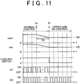
- FIG. 11 is a waveform chart for illustrating a second example of control operation at the time of a change from the normal control mode to the upper arm ON control mode.
- the normal control mode is applied. Furthermore, the standby period T0 is provided from time ta to time tb.
- the AC-DC converter 250 and the DC-DC converter 210 are kept activated, and the normal control mode is applied. Then, the target voltage vdc* of the smoothing capacitor 220 gradually decreases to the battery voltage VB at that time.
- the on/off duty of the switching element Q3 is controlled so that the direct-current voltage vdc decreases with the target voltage vdc*.
- the upper arm ON control mode is applied.
- the control switches 330 and 360 shown in FIG. 7 each are connected to the "b" side.
- the switching element Q1 is kept in an on state.
- the AC-DC converter 250 generates charging current for charging the main battery 10 by converting the power supply voltage vac to direct-current voltage through on/off control over the switching element Q3.
- inrush current that instantaneously occurs when the switching element Q1 is turned on may be suppressed at the time of a start of upper arm ON control. Furthermore, different from the change control shown in FIG. 10 , it is not necessary to provide a discharging resistor for the smoothing capacitor 220, so the efficiency may be further improved.
- the standby period T0 shown in FIG. 10 and FIG. 11 may be terminated after a lapse of a constant period of time on the basis of a timer value, or the like, or may be terminated in response to the fact that it is detected that the direct-current voltage vdc has decreased to the battery voltage VB on the basis of a comparison of detected voltages.
- the configuration of the charging device 200 particularly, the configuration of the AC-DC converter 250 and the configuration of the DC-DC converter 210, are not limited to the illustrated present embodiment. That is, as long as the AC-DC converter 250 is a non-isolated electric power converter that is able to convert the power supply voltage vac, supplied from the external power supply 500, to a direct-current voltage that is higher than the peak voltage of the power supply voltage, a circuit configuration different from the configuration of FIG. 1 may be applied to the AC-DC converter 250.
- the DC-DC converter 210 is a non-isolated configuration that includes a switching element that is arranged so as to form a path that directly supplies current from the AC-DC converter 250 to the main battery 10 when the switching element is kept in an on state and is able to control charging current for charging the main battery 10 when the switching element is subjected to on/off control
- a circuit configuration different from the configuration of FIG. 1 may be applied to the DC-DC converter 210.
- the aspect of the invention may be applied to charging control when an electrical storage device equipped for an electromotive vehicle is charged by a power supply outside the vehicle.
Landscapes
- Engineering & Computer Science (AREA)
- Power Engineering (AREA)
- Transportation (AREA)
- Mechanical Engineering (AREA)
- Charge And Discharge Circuits For Batteries Or The Like (AREA)
- Electric Propulsion And Braking For Vehicles (AREA)
- Dc-Dc Converters (AREA)
- Secondary Cells (AREA)
Claims (7)
- Ladevorrichtung für ein elektromotorisches Fahrzeug, welches mit einer elektrische Speichervorrichtung (10) ausgestattet ist, mit: einem ersten elektrischen Umrichter (250), welcher eine von einer externen Leistungsversorgung (500) zugeführte Wechselspannung in eine Gleichspannung wandelt, die höher als eine Spitzenspannung der Wechselspannung ist, und die Gleichspannung an eine erste Leistungsversorgungsleitung (PL1) ausgibt; und einem zweiten elektrischen Umrichter (210), welcher während eines externes Ladens zum Laden der elektrischen Speichervorrichtung durch die externe Leistungsversorgung (500) eine elektrische Gleichstromleistung zwischen der ersten Leistungsversorgungsleitung und einer zweiten Leistungsversorgungsleitung (PL2) wandelt, welche mit einer positiven Elektrode der elektrischen Speichervorrichtung (10) elektrisch verbunden ist,
wobei der zweite elektrische Umrichter (210) ein erstes Schaltelement (Q1), welches zwischen einem ersten Knoten (N1) und der ersten Leistungsversorgungsleitung (PL1) elektrisch angeschlossen ist, und eine erste Induktanz (L1) aufweist, welche zwischen dem ersten Knoten (N1) und der zweiten Leistungsversorgungsleitung (PL2) elektrisch angeschlossen ist;
wobei die Ladevorrichtung ferner eine Steuerungsvorrichtung (300) aufweist, welche den ersten und den zweiten elektrischen Umrichter steuert;
wobei die Steuerungsvorrichtung (300) während des externen Ladens basierend auf einem Zustand des externen Ladens entweder einen ersten Steuerungsmodus, in welchem die elektrische Speichervorrichtung (10) über das erste Schaltelement (Q1) durch eine An/Aus-Steuerung geladen wird, oder einen zweiten Steuerungsmodus, in welchem die elektrische Speichervorrichtung geladen wird, während das erste Schaltelement (Q1) in einem angeschalteten Zustand gehalten wird, auswählt, und
wobei die Steuerungsvorrichtung (300) eine Steuerungsmodusauswahleinheit (340) aufweist, welche konfiguriert ist, um den zweiten Steuerungsmodus auszuwählen, wenn die Spannung der elektrischen Speichervorrichtung (10) höher als die Spitzenspannung der Wechselspannung ist, und das erste Steuerungsmodell auszuwählen, wenn die Spannung der elektrischen Speichervorrichtung (10) niedriger als die Spitzenspannung der Wechselspannung ist. - Ladevorrichtung nach Anspruch 1, wobei die Steuerungsvorrichtung den zweiten Steuerungsmodus auswählt, wenn eine elektrische Ladeleistung zum Laden der elektrischen Speichervorrichtung niedriger als ein vorbestimmtes Level ist.
- Ladevorrichtung nach Anspruch 1 oder 2, wobei der erste elektrische Umrichter (250) Folgendes aufweist:einen Gleichrichter (D5-D8), welcher die von der externen Leistungsversorgung zugeführte Wechselspannung gleichrichtet und dann die gleichgerichtete Spannung an eine dritte Leistungsversorgungsleitung (PL3) ausgibt;eine zweite Induktanz (L2), welche zwischen der dritten Leistungsversorgungsleitung (PL3) und einem zweiten Knoten (N2) elektrisch angeschlossen ist;eine erste Diode (D4), welche zwischen dem zweiten Knoten (N2) und der ersten Leistungsversorgungsleitung (PL1) derart elektrisch angeschlossen ist, dass eine Richtung von dem zweiten Knoten (N2) zu der ersten Leistungsversorgungsleitung (PL1) als eine Vorwärtsrichtung eingestellt ist; undein zweites Schaltelement (Q3), welches zwischen dem zweiten Knoten (N2) und einer vierten Leistungsversorgungsleitung (GL) elektrisch angeschlossen ist, welche an einer negativen Elektrode der elektrischen Speichervorrichtung elektrisch angeschlossen ist, undwobei die Steuerungsvorrichtung An/Aus-Zustände des zweiten Schaltelements (Q3) derart steuert, dass ein Strom, welcher die zweite Induktanz (L2) durchläuft, mit einem Soll-Strom übereinstimmt, welcher ein Absolutwert eines Wechselstroms ist, dessen eine Phase mit einer Phase der Wechselspannung übereinstimmt, und die Steuerungsvorrichtung eine Amplitude des Soll-Stroms basierend auf einer Spannung der ersten Leistungsversorgungsleitung (PL1) in dem ersten Steuerungsmodus steuert; wohingegen die Steuerungsvorrichtung die Amplitude des Soll-Stroms ungeachtet der Spannung der ersten Leistungsversorgungsleitung (PL1) in dem zweiten Steuerungsmodus konstant hält.
- Ladevorrichtung nach einem der Ansprüche 1 bis 3, wobei die Steuerungsvorrichtung (300) in dem ersten Steuerungsmodus ein Taktverhältnis der An/Aus-Zustände des ersten Schaltelements (Q1) basierend auf einer Differenz zwischen einem Ladestrom zum Laden der elektrischen Speichervorrichtung und einem Soll-Ladestrom steuert.
- Ladevorrichtung nach einem der Ansprüche 1 bis 4, wobei die Steuerungsvorrichtung (300), wenn der Zustand des externen Ladens eine vorbestimmte Bedingung erfüllt, dass der zweite Steuerungsmodus anwendbar ist, während der erste Steuerungsmodus ausgewählt ist, von dem ersten Steuerungsmodus in den zweiten Steuerungsmodus wechselt, nachdem eine Spannung der ersten Leistungsversorgungsleitung auf eine Spannung der elektrischen Speichervorrichtung gesunken ist.
- Ladevorrichtung nach Anspruch 5, wobei die Steuerungsvorrichtung (300), wenn der Zustand des externen Ladens die vorbestimmte Bedingung erfüllt, den ersten und den zweiten elektrischen Umrichter stoppt und die Spannung der ersten Leistungsversorgungsleitung durch Entladen unter Verwendung eines Entladewiderstands senkt.
- Ladevorrichtung nach Anspruch 5, wobei die Steuerungsvorrichtung (300) eine dem zweiten elektrischen Umrichter zugeführte Soll-Spannung der Spannung der ersten Leistungsversorgungsleitung auf die Spannung der elektrischen Speichervorrichtung senkt, wenn der Zustand des externen Ladens die vorbestimmte Bedingung erfüllt.
Applications Claiming Priority (2)
| Application Number | Priority Date | Filing Date | Title |
|---|---|---|---|
| JP2010152945A JP5204157B2 (ja) | 2010-07-05 | 2010-07-05 | 電動車両の充電装置 |
| PCT/IB2011/001555 WO2012004647A2 (en) | 2010-07-05 | 2011-07-04 | Charging device for electromotive vehicle |
Publications (2)
| Publication Number | Publication Date |
|---|---|
| EP2590837A2 EP2590837A2 (de) | 2013-05-15 |
| EP2590837B1 true EP2590837B1 (de) | 2019-10-02 |
Family
ID=44786022
Family Applications (1)
| Application Number | Title | Priority Date | Filing Date |
|---|---|---|---|
| EP11767754.2A Active EP2590837B1 (de) | 2010-07-05 | 2011-07-04 | Ladegerät für elektrofahrzeuge |
Country Status (5)
| Country | Link |
|---|---|
| US (1) | US9236760B2 (de) |
| EP (1) | EP2590837B1 (de) |
| JP (1) | JP5204157B2 (de) |
| CN (1) | CN102985281B (de) |
| WO (1) | WO2012004647A2 (de) |
Families Citing this family (31)
| Publication number | Priority date | Publication date | Assignee | Title |
|---|---|---|---|---|
| DE102012200804A1 (de) * | 2012-01-20 | 2013-07-25 | Continental Automotive Gmbh | Bordnetz und Verfahren zum Betreiben eines Bordnetzes |
| DE102012207809A1 (de) * | 2012-05-10 | 2013-11-14 | Robert Bosch Gmbh | Reichweitenverlängerer, Antrieb und Kraftfahrzeug |
| JP2013255308A (ja) * | 2012-06-05 | 2013-12-19 | Toshiba Corp | 半導体電力変換装置 |
| EP2867975B1 (de) * | 2012-06-27 | 2020-04-15 | BYD Company Limited | Ladesystem, fahrzeug damit und verfahren zur steuerung des ladens eines fahrzeugs damit |
| JP5623584B1 (ja) * | 2013-04-19 | 2014-11-12 | 三菱電機株式会社 | 電動車両管理システム |
| JP6232878B2 (ja) * | 2013-09-24 | 2017-11-22 | トヨタ自動車株式会社 | 蓄電システム |
| JP5850017B2 (ja) * | 2013-10-15 | 2016-02-03 | 株式会社デンソー | バッテリ監視装置 |
| US10742054B2 (en) * | 2014-09-30 | 2020-08-11 | International Business Machines Corporation | Intelligent composable multi-function battery pack |
| GB2540570B (en) * | 2015-07-21 | 2019-04-03 | Dyson Technology Ltd | Battery charger |
| GB2540751B (en) * | 2015-07-21 | 2018-07-04 | Dyson Technology Ltd | Vacuum cleaner having a dual power supply |
| GB2557443B (en) * | 2015-07-21 | 2019-07-10 | Dyson Technology Ltd | Battery charger |
| GB2540572B (en) * | 2015-07-21 | 2018-12-19 | Dyson Technology Ltd | Battery charger |
| GB2540750B (en) * | 2015-07-21 | 2019-04-17 | Dyson Technology Ltd | Power supply |
| US9843206B2 (en) * | 2015-09-11 | 2017-12-12 | Renesas Electronics America Inc. | Transformer less battery charger system |
| KR101876027B1 (ko) * | 2016-06-03 | 2018-07-06 | 현대자동차주식회사 | 친환경 차량의 ldc 제어 장치 및 그 방법 |
| DE102016212543A1 (de) * | 2016-07-11 | 2018-01-11 | Continental Automotive Gmbh | Fahrzeugbordnetze, Ladesystem, Ladestation und Verfahren zur Übertragung von elektrischer Energie |
| GB2552777B (en) * | 2016-07-21 | 2022-06-08 | Petalite Ltd | A battery charging system and method |
| US10673254B2 (en) * | 2016-07-22 | 2020-06-02 | Renesas Electronics America Inc. | Simple battery and charger system |
| KR101907373B1 (ko) * | 2016-11-16 | 2018-10-12 | 현대오트론 주식회사 | 과충전 방지 장치 및 방법 |
| DE102017115631A1 (de) * | 2017-07-12 | 2019-04-11 | Dr. Ing. H.C. F. Porsche Aktiengesellschaft | Vorrichtung zum Laden mindestens einer Batterie |
| CN111630762B (zh) * | 2017-12-22 | 2024-04-02 | Lg伊诺特有限公司 | 包括直流/直流转换器的供电系统及其控制方法 |
| JP6954205B2 (ja) | 2018-03-28 | 2021-10-27 | トヨタ自動車株式会社 | 電力変換器 |
| JP7003803B2 (ja) * | 2018-03-30 | 2022-01-21 | スズキ株式会社 | 車両用電源装置 |
| CA3138373A1 (en) | 2019-03-19 | 2020-09-24 | dcbel Inc. | Ev charger with adaptable charging protocol |
| CN114616122B (zh) * | 2019-08-28 | 2024-01-05 | 斯巴克充电公司 | 电动车充电装置、系统及方法 |
| JP7095672B2 (ja) * | 2019-10-30 | 2022-07-05 | 株式会社デンソー | 電力変換装置 |
| WO2021217291A1 (en) * | 2020-04-26 | 2021-11-04 | Huawei Technologies Co., Ltd. | Power supply and distribution system |
| US12230992B2 (en) * | 2021-01-29 | 2025-02-18 | Lear Corporation | On-board charger (OBC) method and system for detecting phase configuration of mains supply and for diagnosing status of OBC phase configuration relays |
| KR20230015173A (ko) * | 2021-07-22 | 2023-01-31 | 현대자동차주식회사 | 차량의 배터리 충전 시스템 및 충전 방법 |
| CN114498866B (zh) * | 2022-04-19 | 2022-07-29 | 伏达半导体(合肥)有限公司 | 双电池充电装置、方法及其控制器 |
| CN117002272B (zh) * | 2023-08-10 | 2025-03-18 | 湖北月照松电控系统有限公司 | 一种基于dc-dc转换器的统一控制电路及控制方法 |
Family Cites Families (19)
| Publication number | Priority date | Publication date | Assignee | Title |
|---|---|---|---|---|
| US7203048B2 (en) * | 2002-10-24 | 2007-04-10 | 02Micro International Limited | DC to DC controller with inrush current protection |
| US7602167B2 (en) * | 2003-01-06 | 2009-10-13 | Texas Instruments Incorporated | Reconfigurable topology for switching and linear voltage regulators |
| JP4274353B2 (ja) * | 2003-03-13 | 2009-06-03 | 本田技研工業株式会社 | 双方向dc−dcコンバータ |
| US7737658B2 (en) * | 2003-10-27 | 2010-06-15 | Sony Corporation | Battery packs having a charging mode and a discharging mode |
| WO2006031810A2 (en) * | 2004-09-10 | 2006-03-23 | Color Kinetics Incorporated | Power control methods and apparatus for variable loads |
| JP4665569B2 (ja) * | 2004-11-30 | 2011-04-06 | トヨタ自動車株式会社 | 電圧変換装置および電圧変換装置における電圧変換の制御をコンピュータに実行させるためのプログラムを記録したコンピュータ読取り可能な記録媒体 |
| US7359224B2 (en) * | 2005-04-28 | 2008-04-15 | International Rectifier Corporation | Digital implementation of power factor correction |
| JP4517994B2 (ja) * | 2005-09-29 | 2010-08-04 | トヨタ自動車株式会社 | 充電制御装置および電動車両 |
| US20070139010A1 (en) * | 2005-12-20 | 2007-06-21 | General Electric Company | Systems and methods for charging a battery |
| JP4491434B2 (ja) | 2006-05-29 | 2010-06-30 | トヨタ自動車株式会社 | 電力制御装置およびそれを備えた車両 |
| JP4179351B2 (ja) * | 2006-07-07 | 2008-11-12 | トヨタ自動車株式会社 | 電源システムおよびそれを備えた車両、電源システムの制御方法、ならびに電源システムの制御をコンピュータに実行させるためのプログラムを記録したコンピュータ読取可能な記録媒体 |
| JP2008054439A (ja) * | 2006-08-25 | 2008-03-06 | Toyota Motor Corp | 電力システム |
| JP4274257B2 (ja) * | 2007-02-20 | 2009-06-03 | トヨタ自動車株式会社 | ハイブリッド車両 |
| US7990117B2 (en) | 2007-07-06 | 2011-08-02 | Northem Power Systems, Inc. | Low-loss control of DC-DC converters in an energy storage system |
| JP5118913B2 (ja) * | 2007-07-24 | 2013-01-16 | トヨタ自動車株式会社 | 電源システムおよびそれを備えた電動車両ならびに電源システムの制御方法 |
| US8350532B2 (en) * | 2007-12-20 | 2013-01-08 | O2Micro Inc. | Power management systems |
| JP5308682B2 (ja) * | 2008-01-24 | 2013-10-09 | 新電元工業株式会社 | 双方向dc/dcコンバータ |
| JP4315232B1 (ja) * | 2008-03-17 | 2009-08-19 | トヨタ自動車株式会社 | 電動車両 |
| JP4483976B2 (ja) * | 2008-05-12 | 2010-06-16 | トヨタ自動車株式会社 | ハイブリッド車両およびハイブリッド車両の制御方法 |
-
2010
- 2010-07-05 JP JP2010152945A patent/JP5204157B2/ja active Active
-
2011
- 2011-07-04 US US13/805,135 patent/US9236760B2/en active Active
- 2011-07-04 WO PCT/IB2011/001555 patent/WO2012004647A2/en not_active Ceased
- 2011-07-04 EP EP11767754.2A patent/EP2590837B1/de active Active
- 2011-07-04 CN CN201180033087.7A patent/CN102985281B/zh active Active
Non-Patent Citations (1)
| Title |
|---|
| None * |
Also Published As
| Publication number | Publication date |
|---|---|
| JP5204157B2 (ja) | 2013-06-05 |
| CN102985281A (zh) | 2013-03-20 |
| WO2012004647A3 (en) | 2012-08-23 |
| US9236760B2 (en) | 2016-01-12 |
| US20130093394A1 (en) | 2013-04-18 |
| JP2012016239A (ja) | 2012-01-19 |
| EP2590837A2 (de) | 2013-05-15 |
| WO2012004647A2 (en) | 2012-01-12 |
| CN102985281B (zh) | 2015-03-18 |
Similar Documents
| Publication | Publication Date | Title |
|---|---|---|
| EP2590837B1 (de) | Ladegerät für elektrofahrzeuge | |
| CA2763682C (en) | Secondary battery temperature-increasing control apparatus and vehicle including the same, and secondary battery temperature-increasing control method | |
| CN102282749B (zh) | 电力转换器 | |
| EP3531528B1 (de) | Stromversorgungssystem und verfahren zur steuerung davon | |
| JP5306306B2 (ja) | スイッチング電源装置 | |
| US10541549B2 (en) | Power supply apparatus | |
| US9065327B2 (en) | Efficiency optimized power converter with dual voltage power factor correction | |
| US20120112528A1 (en) | Method for controlling a power supply device having an inverter | |
| CN111277133B (zh) | 用于控制车辆的低压直流至直流转换器的装置和方法 | |
| JP2003235252A (ja) | 電源回路 | |
| JP2011239493A (ja) | ハイブリッド式発動発電機の出力制御装置 | |
| WO2012043138A1 (ja) | 電源システム | |
| JP2021078184A (ja) | 車両用充電装置 | |
| JP5225761B2 (ja) | 昇降圧コンバータの駆動制御装置 | |
| JP2011211797A (ja) | 昇圧型dc−dcコンバータ | |
| JP2011091952A (ja) | 電源システム | |
| KR20100138210A (ko) | 다양한 전원을 입력으로 하는 전기자동차 충전용 전력변환장치 | |
| JP6268786B2 (ja) | パワーコンディショナ、パワーコンディショナシステムおよびパワーコンディショナの制御方法 | |
| US20250183810A1 (en) | Efficiency in a dual-active bridge of a dc-dc stage | |
| JP4590959B2 (ja) | 電力変換装置の制御方法、及びこれを用いて駆動される電気車両 | |
| KR20200076785A (ko) | 무체인 전기자전거의 충전시스템 | |
| JP2001253653A (ja) | エレベータシステム | |
| JP2012115018A (ja) | 電力制御装置 | |
| JP2003309927A (ja) | 蓄電システムの運転方法及び蓄電システム | |
| WO2010134179A1 (ja) | コンバータの過電流防止制御装置およびコンバータの過電流防止方法 |
Legal Events
| Date | Code | Title | Description |
|---|---|---|---|
| PUAI | Public reference made under article 153(3) epc to a published international application that has entered the european phase |
Free format text: ORIGINAL CODE: 0009012 |
|
| 17P | Request for examination filed |
Effective date: 20130128 |
|
| AK | Designated contracting states |
Kind code of ref document: A2 Designated state(s): AL AT BE BG CH CY CZ DE DK EE ES FI FR GB GR HR HU IE IS IT LI LT LU LV MC MK MT NL NO PL PT RO RS SE SI SK SM TR |
|
| RAP1 | Party data changed (applicant data changed or rights of an application transferred) |
Owner name: TOYOTA JIDOSHA KABUSHIKI KAISHA |
|
| DAX | Request for extension of the european patent (deleted) | ||
| 17Q | First examination report despatched |
Effective date: 20151105 |
|
| STAA | Information on the status of an ep patent application or granted ep patent |
Free format text: STATUS: EXAMINATION IS IN PROGRESS |
|
| REG | Reference to a national code |
Ref country code: DE Ref legal event code: R079 Ref document number: 602011062455 Country of ref document: DE Free format text: PREVIOUS MAIN CLASS: B60L0011180000 Ipc: H02M0003155000 |
|
| GRAP | Despatch of communication of intention to grant a patent |
Free format text: ORIGINAL CODE: EPIDOSNIGR1 |
|
| STAA | Information on the status of an ep patent application or granted ep patent |
Free format text: STATUS: GRANT OF PATENT IS INTENDED |
|
| RIC1 | Information provided on ipc code assigned before grant |
Ipc: H02M 3/155 20060101AFI20190424BHEP Ipc: B60L 53/20 20190101ALI20190424BHEP |
|
| INTG | Intention to grant announced |
Effective date: 20190514 |
|
| GRAS | Grant fee paid |
Free format text: ORIGINAL CODE: EPIDOSNIGR3 |
|
| GRAA | (expected) grant |
Free format text: ORIGINAL CODE: 0009210 |
|
| STAA | Information on the status of an ep patent application or granted ep patent |
Free format text: STATUS: THE PATENT HAS BEEN GRANTED |
|
| RIN1 | Information on inventor provided before grant (corrected) |
Inventor name: SUGIYAMA, YOSHINOBU Inventor name: IYASU, SEIJI Inventor name: WAKIMOTO, TORU Inventor name: ITAGAKI, KENJI |
|
| AK | Designated contracting states |
Kind code of ref document: B1 Designated state(s): AL AT BE BG CH CY CZ DE DK EE ES FI FR GB GR HR HU IE IS IT LI LT LU LV MC MK MT NL NO PL PT RO RS SE SI SK SM TR |
|
| REG | Reference to a national code |
Ref country code: GB Ref legal event code: FG4D |
|
| REG | Reference to a national code |
Ref country code: CH Ref legal event code: EP Ref country code: AT Ref legal event code: REF Ref document number: 1187314 Country of ref document: AT Kind code of ref document: T Effective date: 20191015 |
|
| REG | Reference to a national code |
Ref country code: DE Ref legal event code: R096 Ref document number: 602011062455 Country of ref document: DE |
|
| REG | Reference to a national code |
Ref country code: IE Ref legal event code: FG4D |
|
| REG | Reference to a national code |
Ref country code: NL Ref legal event code: MP Effective date: 20191002 |
|
| REG | Reference to a national code |
Ref country code: LT Ref legal event code: MG4D |
|
| REG | Reference to a national code |
Ref country code: DE Ref legal event code: R084 Ref document number: 602011062455 Country of ref document: DE |
|
| REG | Reference to a national code |
Ref country code: AT Ref legal event code: MK05 Ref document number: 1187314 Country of ref document: AT Kind code of ref document: T Effective date: 20191002 |
|
| PG25 | Lapsed in a contracting state [announced via postgrant information from national office to epo] |
Ref country code: LV Free format text: LAPSE BECAUSE OF FAILURE TO SUBMIT A TRANSLATION OF THE DESCRIPTION OR TO PAY THE FEE WITHIN THE PRESCRIBED TIME-LIMIT Effective date: 20191002 Ref country code: LT Free format text: LAPSE BECAUSE OF FAILURE TO SUBMIT A TRANSLATION OF THE DESCRIPTION OR TO PAY THE FEE WITHIN THE PRESCRIBED TIME-LIMIT Effective date: 20191002 Ref country code: SE Free format text: LAPSE BECAUSE OF FAILURE TO SUBMIT A TRANSLATION OF THE DESCRIPTION OR TO PAY THE FEE WITHIN THE PRESCRIBED TIME-LIMIT Effective date: 20191002 Ref country code: NL Free format text: LAPSE BECAUSE OF FAILURE TO SUBMIT A TRANSLATION OF THE DESCRIPTION OR TO PAY THE FEE WITHIN THE PRESCRIBED TIME-LIMIT Effective date: 20191002 Ref country code: ES Free format text: LAPSE BECAUSE OF FAILURE TO SUBMIT A TRANSLATION OF THE DESCRIPTION OR TO PAY THE FEE WITHIN THE PRESCRIBED TIME-LIMIT Effective date: 20191002 Ref country code: NO Free format text: LAPSE BECAUSE OF FAILURE TO SUBMIT A TRANSLATION OF THE DESCRIPTION OR TO PAY THE FEE WITHIN THE PRESCRIBED TIME-LIMIT Effective date: 20200102 Ref country code: GR Free format text: LAPSE BECAUSE OF FAILURE TO SUBMIT A TRANSLATION OF THE DESCRIPTION OR TO PAY THE FEE WITHIN THE PRESCRIBED TIME-LIMIT Effective date: 20200103 Ref country code: PL Free format text: LAPSE BECAUSE OF FAILURE TO SUBMIT A TRANSLATION OF THE DESCRIPTION OR TO PAY THE FEE WITHIN THE PRESCRIBED TIME-LIMIT Effective date: 20191002 Ref country code: PT Free format text: LAPSE BECAUSE OF FAILURE TO SUBMIT A TRANSLATION OF THE DESCRIPTION OR TO PAY THE FEE WITHIN THE PRESCRIBED TIME-LIMIT Effective date: 20200203 Ref country code: BG Free format text: LAPSE BECAUSE OF FAILURE TO SUBMIT A TRANSLATION OF THE DESCRIPTION OR TO PAY THE FEE WITHIN THE PRESCRIBED TIME-LIMIT Effective date: 20200102 Ref country code: FI Free format text: LAPSE BECAUSE OF FAILURE TO SUBMIT A TRANSLATION OF THE DESCRIPTION OR TO PAY THE FEE WITHIN THE PRESCRIBED TIME-LIMIT Effective date: 20191002 Ref country code: AT Free format text: LAPSE BECAUSE OF FAILURE TO SUBMIT A TRANSLATION OF THE DESCRIPTION OR TO PAY THE FEE WITHIN THE PRESCRIBED TIME-LIMIT Effective date: 20191002 |
|
| PG25 | Lapsed in a contracting state [announced via postgrant information from national office to epo] |
Ref country code: HR Free format text: LAPSE BECAUSE OF FAILURE TO SUBMIT A TRANSLATION OF THE DESCRIPTION OR TO PAY THE FEE WITHIN THE PRESCRIBED TIME-LIMIT Effective date: 20191002 Ref country code: RS Free format text: LAPSE BECAUSE OF FAILURE TO SUBMIT A TRANSLATION OF THE DESCRIPTION OR TO PAY THE FEE WITHIN THE PRESCRIBED TIME-LIMIT Effective date: 20191002 Ref country code: CZ Free format text: LAPSE BECAUSE OF FAILURE TO SUBMIT A TRANSLATION OF THE DESCRIPTION OR TO PAY THE FEE WITHIN THE PRESCRIBED TIME-LIMIT Effective date: 20191002 Ref country code: IS Free format text: LAPSE BECAUSE OF FAILURE TO SUBMIT A TRANSLATION OF THE DESCRIPTION OR TO PAY THE FEE WITHIN THE PRESCRIBED TIME-LIMIT Effective date: 20200224 |
|
| PG25 | Lapsed in a contracting state [announced via postgrant information from national office to epo] |
Ref country code: AL Free format text: LAPSE BECAUSE OF FAILURE TO SUBMIT A TRANSLATION OF THE DESCRIPTION OR TO PAY THE FEE WITHIN THE PRESCRIBED TIME-LIMIT Effective date: 20191002 |
|
| REG | Reference to a national code |
Ref country code: DE Ref legal event code: R097 Ref document number: 602011062455 Country of ref document: DE |
|
| PG2D | Information on lapse in contracting state deleted |
Ref country code: IS |
|
| PG25 | Lapsed in a contracting state [announced via postgrant information from national office to epo] |
Ref country code: RO Free format text: LAPSE BECAUSE OF FAILURE TO SUBMIT A TRANSLATION OF THE DESCRIPTION OR TO PAY THE FEE WITHIN THE PRESCRIBED TIME-LIMIT Effective date: 20191002 Ref country code: DK Free format text: LAPSE BECAUSE OF FAILURE TO SUBMIT A TRANSLATION OF THE DESCRIPTION OR TO PAY THE FEE WITHIN THE PRESCRIBED TIME-LIMIT Effective date: 20191002 Ref country code: EE Free format text: LAPSE BECAUSE OF FAILURE TO SUBMIT A TRANSLATION OF THE DESCRIPTION OR TO PAY THE FEE WITHIN THE PRESCRIBED TIME-LIMIT Effective date: 20191002 Ref country code: IS Free format text: LAPSE BECAUSE OF FAILURE TO SUBMIT A TRANSLATION OF THE DESCRIPTION OR TO PAY THE FEE WITHIN THE PRESCRIBED TIME-LIMIT Effective date: 20200202 |
|
| PLBE | No opposition filed within time limit |
Free format text: ORIGINAL CODE: 0009261 |
|
| STAA | Information on the status of an ep patent application or granted ep patent |
Free format text: STATUS: NO OPPOSITION FILED WITHIN TIME LIMIT |
|
| PG25 | Lapsed in a contracting state [announced via postgrant information from national office to epo] |
Ref country code: IT Free format text: LAPSE BECAUSE OF FAILURE TO SUBMIT A TRANSLATION OF THE DESCRIPTION OR TO PAY THE FEE WITHIN THE PRESCRIBED TIME-LIMIT Effective date: 20191002 Ref country code: SK Free format text: LAPSE BECAUSE OF FAILURE TO SUBMIT A TRANSLATION OF THE DESCRIPTION OR TO PAY THE FEE WITHIN THE PRESCRIBED TIME-LIMIT Effective date: 20191002 Ref country code: SM Free format text: LAPSE BECAUSE OF FAILURE TO SUBMIT A TRANSLATION OF THE DESCRIPTION OR TO PAY THE FEE WITHIN THE PRESCRIBED TIME-LIMIT Effective date: 20191002 |
|
| 26N | No opposition filed |
Effective date: 20200703 |
|
| PG25 | Lapsed in a contracting state [announced via postgrant information from national office to epo] |
Ref country code: SI Free format text: LAPSE BECAUSE OF FAILURE TO SUBMIT A TRANSLATION OF THE DESCRIPTION OR TO PAY THE FEE WITHIN THE PRESCRIBED TIME-LIMIT Effective date: 20191002 |
|
| PG25 | Lapsed in a contracting state [announced via postgrant information from national office to epo] |
Ref country code: MC Free format text: LAPSE BECAUSE OF FAILURE TO SUBMIT A TRANSLATION OF THE DESCRIPTION OR TO PAY THE FEE WITHIN THE PRESCRIBED TIME-LIMIT Effective date: 20191002 |
|
| REG | Reference to a national code |
Ref country code: CH Ref legal event code: PL |
|
| GBPC | Gb: european patent ceased through non-payment of renewal fee |
Effective date: 20200704 |
|
| REG | Reference to a national code |
Ref country code: BE Ref legal event code: MM Effective date: 20200731 |
|
| PG25 | Lapsed in a contracting state [announced via postgrant information from national office to epo] |
Ref country code: CH Free format text: LAPSE BECAUSE OF NON-PAYMENT OF DUE FEES Effective date: 20200731 Ref country code: IE Free format text: LAPSE BECAUSE OF NON-PAYMENT OF DUE FEES Effective date: 20200704 Ref country code: LI Free format text: LAPSE BECAUSE OF NON-PAYMENT OF DUE FEES Effective date: 20200731 Ref country code: LU Free format text: LAPSE BECAUSE OF NON-PAYMENT OF DUE FEES Effective date: 20200704 Ref country code: GB Free format text: LAPSE BECAUSE OF NON-PAYMENT OF DUE FEES Effective date: 20200704 Ref country code: FR Free format text: LAPSE BECAUSE OF NON-PAYMENT OF DUE FEES Effective date: 20200731 |
|
| PG25 | Lapsed in a contracting state [announced via postgrant information from national office to epo] |
Ref country code: BE Free format text: LAPSE BECAUSE OF NON-PAYMENT OF DUE FEES Effective date: 20200731 |
|
| PG25 | Lapsed in a contracting state [announced via postgrant information from national office to epo] |
Ref country code: TR Free format text: LAPSE BECAUSE OF FAILURE TO SUBMIT A TRANSLATION OF THE DESCRIPTION OR TO PAY THE FEE WITHIN THE PRESCRIBED TIME-LIMIT Effective date: 20191002 Ref country code: MT Free format text: LAPSE BECAUSE OF FAILURE TO SUBMIT A TRANSLATION OF THE DESCRIPTION OR TO PAY THE FEE WITHIN THE PRESCRIBED TIME-LIMIT Effective date: 20191002 Ref country code: CY Free format text: LAPSE BECAUSE OF FAILURE TO SUBMIT A TRANSLATION OF THE DESCRIPTION OR TO PAY THE FEE WITHIN THE PRESCRIBED TIME-LIMIT Effective date: 20191002 |
|
| PG25 | Lapsed in a contracting state [announced via postgrant information from national office to epo] |
Ref country code: MK Free format text: LAPSE BECAUSE OF FAILURE TO SUBMIT A TRANSLATION OF THE DESCRIPTION OR TO PAY THE FEE WITHIN THE PRESCRIBED TIME-LIMIT Effective date: 20191002 |
|
| P01 | Opt-out of the competence of the unified patent court (upc) registered |
Effective date: 20230427 |
|
| PGFP | Annual fee paid to national office [announced via postgrant information from national office to epo] |
Ref country code: DE Payment date: 20250507 Year of fee payment: 15 |