EP2590218A1 - Überspannungs-ESD- und Überspannungsschutz mit CMOS-Einstellung für LED-Anwendung - Google Patents
Überspannungs-ESD- und Überspannungsschutz mit CMOS-Einstellung für LED-Anwendung Download PDFInfo
- Publication number
- EP2590218A1 EP2590218A1 EP12180332.4A EP12180332A EP2590218A1 EP 2590218 A1 EP2590218 A1 EP 2590218A1 EP 12180332 A EP12180332 A EP 12180332A EP 2590218 A1 EP2590218 A1 EP 2590218A1
- Authority
- EP
- European Patent Office
- Prior art keywords
- diodes
- transistor
- input
- protection circuit
- resistor
- Prior art date
- Legal status (The legal status is an assumption and is not a legal conclusion. Google has not performed a legal analysis and makes no representation as to the accuracy of the status listed.)
- Granted
Links
- XUIMIQQOPSSXEZ-UHFFFAOYSA-N Silicon Chemical compound [Si] XUIMIQQOPSSXEZ-UHFFFAOYSA-N 0.000 claims abstract description 16
- 229910052710 silicon Inorganic materials 0.000 claims abstract description 16
- 239000010703 silicon Substances 0.000 claims abstract description 16
- 230000015556 catabolic process Effects 0.000 description 15
- 238000000034 method Methods 0.000 description 8
- 238000010586 diagram Methods 0.000 description 5
- 238000004519 manufacturing process Methods 0.000 description 4
- 230000000873 masking effect Effects 0.000 description 4
- 239000000758 substrate Substances 0.000 description 4
- 238000009792 diffusion process Methods 0.000 description 3
- 238000012986 modification Methods 0.000 description 2
- 230000004048 modification Effects 0.000 description 2
- 230000035882 stress Effects 0.000 description 2
- 239000013078 crystal Substances 0.000 description 1
- 230000007423 decrease Effects 0.000 description 1
- 230000006355 external stress Effects 0.000 description 1
- 238000013021 overheating Methods 0.000 description 1
Images


Classifications
-
- H—ELECTRICITY
- H05—ELECTRIC TECHNIQUES NOT OTHERWISE PROVIDED FOR
- H05B—ELECTRIC HEATING; ELECTRIC LIGHT SOURCES NOT OTHERWISE PROVIDED FOR; CIRCUIT ARRANGEMENTS FOR ELECTRIC LIGHT SOURCES, IN GENERAL
- H05B45/00—Circuit arrangements for operating light-emitting diodes [LED]
- H05B45/50—Circuit arrangements for operating light-emitting diodes [LED] responsive to malfunctions or undesirable behaviour of LEDs; responsive to LED life; Protective circuits
- H05B45/54—Circuit arrangements for operating light-emitting diodes [LED] responsive to malfunctions or undesirable behaviour of LEDs; responsive to LED life; Protective circuits in a series array of LEDs
-
- H—ELECTRICITY
- H01—ELECTRIC ELEMENTS
- H01L—SEMICONDUCTOR DEVICES NOT COVERED BY CLASS H10
- H01L27/00—Devices consisting of a plurality of semiconductor or other solid-state components formed in or on a common substrate
- H01L27/02—Devices consisting of a plurality of semiconductor or other solid-state components formed in or on a common substrate including semiconductor components specially adapted for rectifying, oscillating, amplifying or switching and having at least one potential-jump barrier or surface barrier; including integrated passive circuit elements with at least one potential-jump barrier or surface barrier
- H01L27/0203—Particular design considerations for integrated circuits
- H01L27/0248—Particular design considerations for integrated circuits for electrical or thermal protection, e.g. electrostatic discharge [ESD] protection
- H01L27/0251—Particular design considerations for integrated circuits for electrical or thermal protection, e.g. electrostatic discharge [ESD] protection for MOS devices
- H01L27/0255—Particular design considerations for integrated circuits for electrical or thermal protection, e.g. electrostatic discharge [ESD] protection for MOS devices using diodes as protective elements
-
- Y—GENERAL TAGGING OF NEW TECHNOLOGICAL DEVELOPMENTS; GENERAL TAGGING OF CROSS-SECTIONAL TECHNOLOGIES SPANNING OVER SEVERAL SECTIONS OF THE IPC; TECHNICAL SUBJECTS COVERED BY FORMER USPC CROSS-REFERENCE ART COLLECTIONS [XRACs] AND DIGESTS
- Y02—TECHNOLOGIES OR APPLICATIONS FOR MITIGATION OR ADAPTATION AGAINST CLIMATE CHANGE
- Y02B—CLIMATE CHANGE MITIGATION TECHNOLOGIES RELATED TO BUILDINGS, e.g. HOUSING, HOUSE APPLIANCES OR RELATED END-USER APPLICATIONS
- Y02B20/00—Energy efficient lighting technologies, e.g. halogen lamps or gas discharge lamps
- Y02B20/30—Semiconductor lamps, e.g. solid state lamps [SSL] light emitting diodes [LED] or organic LED [OLED]
Definitions
- CMOS adjustable over voltage electrostatic discharge (ESD) and surge protection for LED application relate generally to a CMOS adjustable over voltage electrostatic discharge (ESD) and surge protection for LED application.
- ESD electrostatic discharge
- LEDs Light Emitting Diodes
- ESD electrostatic discharge
- the LEDs may also experience over voltage application to the LED. This over voltage stress may cause permanent damage. Consequently, the LEDs need ESD and overvoltage protection. This protection may be provided by a protection device.
- a protection device may work as a bypass, offering a low resistance current path parallel to the failed diode. Accordingly, the driving current is not blocked by the failed LED so that the remaining LEDs may continue to work.
- Zener diodes may be Zener diodes and other discrete solutions. Usually a Zener diode protects one LED. When creating a LED bank with more than one diode in series the Zener diodes are placed parallel to each LED. If an over voltage event occurs, the Zener diode shunts current. But this configuration does not work as a bypass for an failed open LED because the voltage drop of the Zener diode in combination with the driving current causes to much heat.
- An alternative discrete solution is to replace the Zener diode by an active circuit that offers a lower on resistance which allows creating a bypass when a LED fails.
- the main problem with all of these protection elements is a slow turn on time. A slow turn on time decreases the field of application for the LEDS and cannot be used for fast switching applications, such as for example, using a LED in a pulse width modulation (PWM) module.
- PWM pulse width modulation
- Various embodiments may also relate to a light emitting diode protection circuit, including: a plurality of diodes connected in series; an input connected to a first diode of the plurality of diodes; an output; a first resistor connected between the plurality of diodes and the output; a transistor with a gate connected to a junction between the first resistor and the plurality of diodes and a source connected to the output; a second resistor connected between the input and drain of the transistor; and a silicon controlled rectifier (SCR) with an anode connected to the input, a base connected to the drain of the transistor, and a cathode connected to the output.
- SCR silicon controlled rectifier
- Various embodiments may also relate to a light emitting diode protection circuit, comprising: a plurality of diodes connected in series; an input connected to a first diode of the plurality of diodes; an output; a first resistor connected between the plurality of diodes and the output; a transistor with a gate connected to a junction between the first resistor and the plurality of diodes and a source connected to the output; and a silicon controlled rectifier (SCR) with an anode connected to the input, a base connected to the drain of the transistor, and a cathode connected to the output.
- SCR silicon controlled rectifier
- Various embodiments may also relate to a light emitting diode (LED) system, including: a plurality of LEDs connected in series; a LED protection circuit connected in parallel to each of the LEDs connected in series further including: a plurality of diodes connected in series; an input connected to a first diode of the plurality of diodes and to the anode of the LED; an output connected to the cathode of the LED; a first resistor connected between the plurality of diodes and the output; a transistor with a gate connected to a junction between the first resistor and the plurality of diodes and a source connected to the output; and a silicon controlled rectifier (SCR) with an anode connected to the input, a base connected to the drain of the transistor, and a cathode connected to the output.
- SCR silicon controlled rectifier
- FIG. 1 is a circuit diagram illustrating an embodiment of the protection circuit
- FIG. 2 is a cross section of an embodiment of a silicon controlled rectifier
- FIG. 3 is a circuit diagram illustrating another embodiment of the protection circuit
- FIG. 4 is a cross section of another embodiment of a silicon controlled rectifier
- FIG. 5 illustrates a light emitting diode system using the protection circuit.
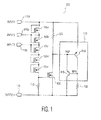
- FIG. 1 is a circuit diagram illustrating an embodiment of the protection circuit.
- the protection circuit 100 may include a plurality of transistor diodes connected in series 105a-105e, a first resistor 110, inputs 115a-115c, the output 120, a second resistor 125, a MOS transistor 130, a silicon controlled rectifier (SCR) 135, and a third resistor 150.
- SCR silicon controlled rectifier
- the plurality of transistor diodes connected in series 105 may be connected in series with a first resistor 110.
- a first input 115a may be connected to a first transistor diode 105a.
- the protection circuit 100 may also include additional inputs such as 115b and 115c. These additional inputs may be attached between various of the plurality of transistor diodes 105.
- the first resistor 110 may also be connected to an output 120.
- a second resistor 125 may be connected between the input 115a and the anode of the SCR 135.
- the CMOS transistor 130 may have a gate connected to a junction between a plurality of transistor diodes 105 and the first resistor 110.
- the MOS transistor also may have a source connected to the output 120 and a drain connected to the second resistor 125 and the gate of the SCR 135.
- the SCR 135 may have an anode connected to the input 115a and the second resistor 125 and a cathode connected to the output 120. While transistor diodes are discussed in this embodiment, other types of diodes may be used as well.
- the protection circuit 100 may provide ESD and surge protection to a LED.
- an input voltage is applied to the input 115a that is higher than the breakdown voltage of the plurality of transistor diodes 105, then current will flow through the plurality of transistor diodes 105 and through the first resistor 110. Accordingly, the number of transistor diodes 105 is selected to provide a desired breakdown voltage.
- additional inputs 115b and 115c allow for additional control over the breakdown voltage used to protect the LED.
- a second input 115b connects to a junction between a first transistor diode 105a and a second transistor diode 105b.
- the breakdown voltage of the plurality of transistor diodes 105 may be reduced.
- the input 115c illustrates how the breakdown voltage may be further reduced.
- the number and location of the multiple inputs 115 may be selected to provide a desired variety of breakdown voltages that may be available when combining the protection circuit 100 with a LED.
- the protection circuit 100 When an input voltage exceeding the break down voltage of the plurality of transistor diodes 105 is applied to the input 115 of the protection circuit 100, current may flow through the plurality of transistor diodes 105 and the first resistor 110. The current flow may result in a voltage across the first resistor 110, which voltage may also be applied to the gate of the MOS transistor 130. This voltage may turn on the MOS transistor 130 allowing the current to flow through the first resistor 125 and the MOS transistor 130. The current may flow through this path because its resistance may be lower than the resistance through the plurality of transistor diodes 105 and the first resistor 110.
- the current flowing through the second transistor 125 may result in a voltage being applied between the anode and the gate of the SCR 135, which turns on the SCR 135, thus allowing current from the input to flow through the SCR 135. Because the SCR 135 may have a low impedance, less power may be lost, and less heat may be generated.
- the voltage across the LED may increase to a value above the breakdown voltage of the plurality of transistor diodes 105. Accordingly, the protection circuit 100 becomes active, and the input current bypasses the failed LED allowing other LEDs that may be connected in series to continue to operate.
- the SCR 135 is illustrated as including a PNP transistor 140 and a NPN transistor 145. This illustration of the SCR indicates the traditional structure of an SCR using two bipolar transistors.
- FIG. 2 is a cross section of an embodiment of a silicon controlled rectifier.
- the SCR 200 may be fabricated using standard CMOS processes.
- the SCR 200 includes a p-substrate 205, a n-well 210, a p-well 215, a first n+ region 220, a first p+ region 225, a second n+ region 230, and second p+ region 235.
- a first silicon layer may be formed and doped to produce the p-substrate 205.
- a second silicon layer may be formed, and doping is applied to create an n-well 210 and a p-well 215.
- the first n+ region 220 and the second n+ region 230 may be formed.
- the first p+ region 225 and the second p+ region 235 may be formed.
- the diffusions used for building the transistors may be re-used: the first n+ region 220 may be built similar to the bulk contact of the PMOS-transistor, the first p+ region 225 may be built similar to the source-drain-diffusion of the PMOS, n-well 210 may be built similar to the n-well of the PMOS; the second p+ region 235 may be built similar to the bulk contact of the NMOS-transistor, the second n+ region 230 may be built similar to the source-drain-diffusion of the NMOS, and the p-well 215 may be built similar to the p-well of the NMOS;
- first n+ region 220 which may act as the gate of the SCR 200, may be connected to the drain of the MOS transistor 130.
- the first p+ region 225 which may act as the anode, may be connected to the input 115.
- second n+ region 230 and the second p+ region 235 which may act as the cathode, may be connected to the output 120.
- This implementation of the SCR 200 is provided for illustration purposes. Other designs and structures for the SCR 200 may be used that are compatible with CMOS manufacturing processes.
- the design of the MOS transistor 130 and the SCR 135 may be driven by the speed at which the LED will be operated.
- FIG. 3 is a circuit diagram illustrating an embodiment of the protection circuit.
- the protection circuit 300 may include a plurality of transistor diodes connected in series 305a-305e, a first resistor 310, inputs 315a-315c, the output 320, a second resistor 325, a MOS transistor 330, a silicon controlled rectifier (SCR) 335, and a third resistor 350.
- SCR silicon controlled rectifier
- the plurality of transistor diodes connected in series 305 may be connected in series with a first resistor 310.
- a first input 315a may be connected to a first transistor diode 305a.
- the protection circuit 300 may also include additional inputs such as 315b and 315c. These additional inputs may be attached between various of the plurality of transistor diodes 305.
- the first resistor 310 may also be connected to an output 320.
- a second resistor 325 may be connected between the gate of the SCR 335 and the drain of the MOS transistor 330, but this resistor may also be omitted.
- the MOS transistor 330 may have a base connected to a junction between a plurality of transistor diodes 305 and the first resistor 310.
- the SCR 335 may have an anode connected to the input 315a and a cathode connected to the output 320.
- the plurality of transistor diodes 305 may provide ESD and surge protection to a LED.
- an input voltage is applied to the input 315a that is higher than the breakdown voltage of the plurality of transistor diodes 305, then current will flow through the plurality of transistor diodes 305 and through the first resistor 310. Accordingly, the number of transistor diodes 305 is selected to provide a desired breakdown voltage.
- additional inputs 315b and 315c allow for additional control over the breakdown voltage used to protect the LED.
- a second input 315b connects to a junction between a first transistor diode 305a and a second transistor diode 305b.
- the breakdown voltage of the plurality of transistor diodes 305 may be reduced.
- the input 315c illustrates how the breakdown voltage may be further reduced.
- the number and location of the multiple inputs 315 may be selected to provide a desired variety of breakdown voltages that may be available when combining the protection circuit 300 with a LED.
- the protection circuit 300 When an input voltage exceeding the break down voltage of the plurality of transistor diodes 305 is applied to the input 315 of the protection circuit 300, current may flow through the plurality of transistor diodes 305 and the first resistor 310. The current flow may result in a voltage across the first resistor 310, which voltage may also be applied to the gate of the MOS transistor 330. This voltage may turn on the MOS transistor 330, which allows current to flow between the anode and the gate of the SCR 335 and through the MOS transistor 330. This current flow turns on the SCR 335, thus allowing current from the input to flow through the SCR 335.
- the SCR 335 Until the SCR 335 reaches its low ohmic state (this is during the turn on time of the SCR) the current flow between the anode and the gate of the SCR 335 and through the MOS transistor 330 will drain the external stress to the output, thus protecting the LED placed in parallel from damage due to over current and or over voltage. Thus a protection device with fast turn on switching is realized. Because the SCR 335 may have a low impedance, less power may be lost, and less heat may be generated.
- the voltage across the LED may increase to a value above the breakdown voltage of the plurality of transistor diodes 305. Accordingly, the protection circuit 300 becomes active, and the input current bypasses the failed LED allowing other LEDs that may be connected in series to continue to operate.
- the SCR 335 is illustrated as including a PNP transistor 340 and a NPN transistor 345. This illustration of the SCR indicates the traditional structure of an SCR using two bipolar transistors.
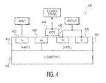
- FIG. 4 is a cross section of another embodiment of a silicon controlled rectifier that also includes the MOS transistor 330.
- the SCR 400 may be fabricated using standard CMOS processes.
- the SCR 400 includes a p-substrate 405, a n-well 410, a p-well 415, a first n+ region 420, a first p+ region 425, a second n+ region 430, second p+ region 435, and a gate 440.
- a first silicon layer may be formed and doped to produce the p-substrate 405.
- a second silicon layer may be formed, and doping is applied to create an n-well 410 and a p-well 415.
- the first n+ region 420 and the second n+ region 430 may be formed.
- the first p+ region 425 and the second p+ region 435 may be formed.
- the gate 440 may be formed over a portion of the p-well 415 and a portion of the first and second n+ regions 420, 430.
- first p+ region 425 which may act as the anode
- second n+ region 430 and the second p+ region 435 which may act as the cathode
- SCR 400 This implementation of the SCR 400 is provided for illustration purposes. Other designs and structures for the SCR 400 may be used that are compatible with CMOS manufacturing processes.
- the design of the MOS transistor 330 and the SCR 335 may be desire able to have short channel lengths. These short channel lengths allow for fast turn on times for use in high speed applications. Thus, the design of the MOS transistor 330 and the SCR 335 may driven by the speed at which the LED will be operated.
- the protection circuits described above may be designed in a standard CMOS process.
- the advantage of this protection circuit is the combination of an ESD and surge protection with a fast turn on time provided by a combination of a MOS transistor and a SCR.
- the SCR typically has a small voltage drop. As a result, it may be possible to handle current in ranges of more than 500mA without overheating.
- the protection circuit further may be designed with an adjustable breakdown voltage for a wide working range by selecting among a plurality of inputs.
- the compact CMOS design allows a placement of other different active circuits (e . g . , LED driver and supply units) on the same die.
- the compact design also may allow several of the protection devices 100 to be placed on one crystal.
- the solution may be produced in a packaged device or as chip scale package.
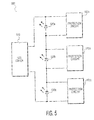
- FIG. 5 illustrates a light emitting diode system using the protection circuit.
- the LED system 500 may include LEDs 520a, 520b, and 520c that may be connected in series. Each of the LEDs 520a, 520b, and 530c may have a protection circuit 100a, 100b, and 100c connected in parallel.
- the LEDs 520 may be driven by a LED driver 510. If LED 520b fails, then the protection circuit 100b may route current applied to the failed LED 520b around failed LED 520b. This allows current to still flow to LEDs 520a and 520c, thus preventing the complete failure of the LED system 500. Further, if there is a current or voltage surge applied to the LEDs 520, the protection circuits 100 will route the current or voltage away from the LEDs to prevent damage to the LEDs.
Landscapes
- Metal-Oxide And Bipolar Metal-Oxide Semiconductor Integrated Circuits (AREA)
- Semiconductor Integrated Circuits (AREA)
- Led Devices (AREA)
Applications Claiming Priority (1)
| Application Number | Priority Date | Filing Date | Title |
|---|---|---|---|
| US13/288,570 US9451669B2 (en) | 2011-11-03 | 2011-11-03 | CMOS adjustable over voltage ESD and surge protection for LED application |
Publications (2)
| Publication Number | Publication Date |
|---|---|
| EP2590218A1 true EP2590218A1 (de) | 2013-05-08 |
| EP2590218B1 EP2590218B1 (de) | 2014-06-04 |
Family
ID=46796309
Family Applications (1)
| Application Number | Title | Priority Date | Filing Date |
|---|---|---|---|
| EP12180332.4A Active EP2590218B1 (de) | 2011-11-03 | 2012-08-13 | Überspannungs-ESD- und Überspannungsschutz mit CMOS-Einstellung für LED-Anwendung |
Country Status (3)
| Country | Link |
|---|---|
| US (1) | US9451669B2 (de) |
| EP (1) | EP2590218B1 (de) |
| CN (1) | CN103094893B (de) |
Cited By (1)
| Publication number | Priority date | Publication date | Assignee | Title |
|---|---|---|---|---|
| CN105337245A (zh) * | 2015-09-28 | 2016-02-17 | 马忠良 | 一种热稳定脱扣装置及电源防雷器 |
Families Citing this family (8)
| Publication number | Priority date | Publication date | Assignee | Title |
|---|---|---|---|---|
| TWI535331B (zh) * | 2011-01-31 | 2016-05-21 | Midas Wei Trading Co Ltd | Light emitting diode protection circuit |
| CN104835818B (zh) * | 2015-05-04 | 2019-09-27 | 武汉新芯集成电路制造有限公司 | 一种双触发lvtscr结构及其电路 |
| US9640523B2 (en) * | 2015-09-08 | 2017-05-02 | Hong Kong Applied Science and Technology Research Institute Company Limited | Lateral-diode, vertical-SCR hybrid structure for high-level ESD protection |
| US10698015B2 (en) * | 2017-10-11 | 2020-06-30 | Rey Dandy Provido Lachica | Systems and methods to facilitate detecting an electromagnetic radiation in a space by using a self-powered radio frequency device (SP-RF device) |
| US11303116B2 (en) * | 2018-08-29 | 2022-04-12 | Allegro Microsystems, Llc | Methods and apparatus for electrical overstress protection |
| US10892258B2 (en) * | 2019-01-04 | 2021-01-12 | Nxp B.V. | ESD-robust stacked driver |
| CN112018742B (zh) * | 2020-08-25 | 2022-04-19 | 中国科学院上海高等研究院 | 一种具有温度补偿的过压保护电路及其实现方法 |
| US11776952B1 (en) | 2022-05-05 | 2023-10-03 | Globalfoundries U.S. Inc. | Silicon-controlled rectifiers for an electrostatic discharge protection device |
Citations (4)
| Publication number | Priority date | Publication date | Assignee | Title |
|---|---|---|---|---|
| EP1355355A2 (de) * | 2002-04-19 | 2003-10-22 | Kabushiki Kaisha Toshiba | Schutzschaltung als Teil einer Halbleiterschaltung |
| US20050057866A1 (en) * | 2001-03-16 | 2005-03-17 | Mergens Markus Paul Josef | Electrostatic discharge protection structures for high speed technologies with mixed and ultra-low voltage supplies |
| US20050173727A1 (en) * | 2004-02-11 | 2005-08-11 | Chartered Semiconductor Manufacturing Ltd. | Triggered silicon controlled rectifier for RF ESD protection |
| US20050264963A1 (en) * | 2004-05-25 | 2005-12-01 | Koichi Sato | Electrostatic discharge protective circuit and semiconductor integrated circuit using the same |
Family Cites Families (9)
| Publication number | Priority date | Publication date | Assignee | Title |
|---|---|---|---|---|
| US7262752B2 (en) * | 2001-01-16 | 2007-08-28 | Visteon Global Technologies, Inc. | Series led backlight control circuit |
| US6717559B2 (en) | 2001-01-16 | 2004-04-06 | Visteon Global Technologies, Inc. | Temperature compensated parallel LED drive circuit |
| US20030076636A1 (en) * | 2001-10-23 | 2003-04-24 | Ming-Dou Ker | On-chip ESD protection circuit with a substrate-triggered SCR device |
| JP3773506B2 (ja) | 2003-07-24 | 2006-05-10 | 松下電器産業株式会社 | 半導体集積回路装置 |
| US6976814B2 (en) | 2003-10-09 | 2005-12-20 | Greg Newman | Workpiece clamping device for automated machining processes |
| JP4504850B2 (ja) * | 2005-03-17 | 2010-07-14 | パナソニック株式会社 | 半導体集積回路装置 |
| US8120887B2 (en) * | 2007-02-28 | 2012-02-21 | Alpha & Omega Semiconductor, Ltd. | MOS transistor triggered transient voltage suppressor to provide circuit protection at a lower voltage |
| CN201199010Y (zh) | 2008-04-24 | 2009-02-25 | 辽宁九通电力电子有限公司 | 具有输出保护功能的串联led驱动智能控制系统 |
| US8373956B2 (en) * | 2010-11-11 | 2013-02-12 | International Business Machines Corporation | Low leakage electrostatic discharge protection circuit |
-
2011
- 2011-11-03 US US13/288,570 patent/US9451669B2/en active Active
-
2012
- 2012-08-13 EP EP12180332.4A patent/EP2590218B1/de active Active
- 2012-10-29 CN CN201210422160.6A patent/CN103094893B/zh active Active
Patent Citations (4)
| Publication number | Priority date | Publication date | Assignee | Title |
|---|---|---|---|---|
| US20050057866A1 (en) * | 2001-03-16 | 2005-03-17 | Mergens Markus Paul Josef | Electrostatic discharge protection structures for high speed technologies with mixed and ultra-low voltage supplies |
| EP1355355A2 (de) * | 2002-04-19 | 2003-10-22 | Kabushiki Kaisha Toshiba | Schutzschaltung als Teil einer Halbleiterschaltung |
| US20050173727A1 (en) * | 2004-02-11 | 2005-08-11 | Chartered Semiconductor Manufacturing Ltd. | Triggered silicon controlled rectifier for RF ESD protection |
| US20050264963A1 (en) * | 2004-05-25 | 2005-12-01 | Koichi Sato | Electrostatic discharge protective circuit and semiconductor integrated circuit using the same |
Cited By (2)
| Publication number | Priority date | Publication date | Assignee | Title |
|---|---|---|---|---|
| CN105337245A (zh) * | 2015-09-28 | 2016-02-17 | 马忠良 | 一种热稳定脱扣装置及电源防雷器 |
| CN105337245B (zh) * | 2015-09-28 | 2018-05-25 | 马忠良 | 一种热稳定脱扣装置及电源防雷器 |
Also Published As
| Publication number | Publication date |
|---|---|
| US9451669B2 (en) | 2016-09-20 |
| EP2590218B1 (de) | 2014-06-04 |
| CN103094893A (zh) | 2013-05-08 |
| US20130114169A1 (en) | 2013-05-09 |
| CN103094893B (zh) | 2015-07-15 |
Similar Documents
| Publication | Publication Date | Title |
|---|---|---|
| EP2590218B1 (de) | Überspannungs-ESD- und Überspannungsschutz mit CMOS-Einstellung für LED-Anwendung | |
| US7755870B2 (en) | Semiconductor integrated circuit device | |
| US20140355157A1 (en) | Electrostatic Discharge (ESD) Protection Circuit with EOS and Latch-Up Immunity | |
| US8675323B2 (en) | Method of manufacturing a package | |
| US7352014B2 (en) | Semiconductor device based on a SCR | |
| US20070230073A1 (en) | High-voltage tolerant power-rail esd clamp circuit | |
| US10263419B2 (en) | Transient voltage protection circuits, devices, and methods | |
| US9704849B2 (en) | Electrostatic discharge protection device structures and methods of manufacture | |
| CN101436592A (zh) | 半导体集成电路 | |
| US9343413B2 (en) | ESD protection for high voltage applications | |
| CN104205345A (zh) | 具有交替导电类型的区域的用于静电放电保护的半导体装置 | |
| TWI765956B (zh) | 半導體裝置 | |
| JP2006080160A (ja) | 静電保護回路 | |
| US8817437B2 (en) | High voltage open-drain electrostatic discharge (ESD) protection device | |
| US9236733B2 (en) | Electrostatic discharge protection | |
| US9812437B2 (en) | Semiconductor integrated circuit device, and electronic appliance using the same | |
| JP2007227697A (ja) | 半導体装置および半導体集積装置 | |
| US6433407B2 (en) | Semiconductor integrated circuit | |
| KR20110070001A (ko) | 반도체 장치용 정전기 방전 보호 장치 및 그의 레이아웃 방법 | |
| US8866200B2 (en) | JFET ESD protection circuit for low voltage applications | |
| KR101006095B1 (ko) | 저전압 동작형 정전기 보호회로 | |
| JP6222381B2 (ja) | 半導体装置および負電位印加防止方法 | |
| JP2005123570A (ja) | 静電放電保護回路 | |
| CN103165594A (zh) | 静电放电保护装置 | |
| KR20140119943A (ko) | 정전기 보호 기능을 갖는 반도체 소자 및 정전기 방지 소자 |
Legal Events
| Date | Code | Title | Description |
|---|---|---|---|
| PUAI | Public reference made under article 153(3) epc to a published international application that has entered the european phase |
Free format text: ORIGINAL CODE: 0009012 |
|
| AK | Designated contracting states |
Kind code of ref document: A1 Designated state(s): AL AT BE BG CH CY CZ DE DK EE ES FI FR GB GR HR HU IE IS IT LI LT LU LV MC MK MT NL NO PL PT RO RS SE SI SK SM TR |
|
| AX | Request for extension of the european patent |
Extension state: BA ME |
|
| 17P | Request for examination filed |
Effective date: 20131108 |
|
| RBV | Designated contracting states (corrected) |
Designated state(s): AL AT BE BG CH CY CZ DE DK EE ES FI FR GB GR HR HU IE IS IT LI LT LU LV MC MK MT NL NO PL PT RO RS SE SI SK SM TR |
|
| GRAP | Despatch of communication of intention to grant a patent |
Free format text: ORIGINAL CODE: EPIDOSNIGR1 |
|
| INTG | Intention to grant announced |
Effective date: 20140131 |
|
| GRAS | Grant fee paid |
Free format text: ORIGINAL CODE: EPIDOSNIGR3 |
|
| GRAA | (expected) grant |
Free format text: ORIGINAL CODE: 0009210 |
|
| AK | Designated contracting states |
Kind code of ref document: B1 Designated state(s): AL AT BE BG CH CY CZ DE DK EE ES FI FR GB GR HR HU IE IS IT LI LT LU LV MC MK MT NL NO PL PT RO RS SE SI SK SM TR |
|
| REG | Reference to a national code |
Ref country code: GB Ref legal event code: FG4D |
|
| REG | Reference to a national code |
Ref country code: CH Ref legal event code: EP |
|
| REG | Reference to a national code |
Ref country code: AT Ref legal event code: REF Ref document number: 671510 Country of ref document: AT Kind code of ref document: T Effective date: 20140615 |
|
| REG | Reference to a national code |
Ref country code: IE Ref legal event code: FG4D |
|
| REG | Reference to a national code |
Ref country code: DE Ref legal event code: R096 Ref document number: 602012001969 Country of ref document: DE Effective date: 20140717 |
|
| REG | Reference to a national code |
Ref country code: AT Ref legal event code: MK05 Ref document number: 671510 Country of ref document: AT Kind code of ref document: T Effective date: 20140604 |
|
| REG | Reference to a national code |
Ref country code: NL Ref legal event code: VDEP Effective date: 20140604 |
|
| PG25 | Lapsed in a contracting state [announced via postgrant information from national office to epo] |
Ref country code: LT Free format text: LAPSE BECAUSE OF FAILURE TO SUBMIT A TRANSLATION OF THE DESCRIPTION OR TO PAY THE FEE WITHIN THE PRESCRIBED TIME-LIMIT Effective date: 20140604 Ref country code: NO Free format text: LAPSE BECAUSE OF FAILURE TO SUBMIT A TRANSLATION OF THE DESCRIPTION OR TO PAY THE FEE WITHIN THE PRESCRIBED TIME-LIMIT Effective date: 20140904 Ref country code: CY Free format text: LAPSE BECAUSE OF FAILURE TO SUBMIT A TRANSLATION OF THE DESCRIPTION OR TO PAY THE FEE WITHIN THE PRESCRIBED TIME-LIMIT Effective date: 20140604 Ref country code: GR Free format text: LAPSE BECAUSE OF FAILURE TO SUBMIT A TRANSLATION OF THE DESCRIPTION OR TO PAY THE FEE WITHIN THE PRESCRIBED TIME-LIMIT Effective date: 20140905 Ref country code: FI Free format text: LAPSE BECAUSE OF FAILURE TO SUBMIT A TRANSLATION OF THE DESCRIPTION OR TO PAY THE FEE WITHIN THE PRESCRIBED TIME-LIMIT Effective date: 20140604 |
|
| REG | Reference to a national code |
Ref country code: LT Ref legal event code: MG4D |
|
| PG25 | Lapsed in a contracting state [announced via postgrant information from national office to epo] |
Ref country code: LV Free format text: LAPSE BECAUSE OF FAILURE TO SUBMIT A TRANSLATION OF THE DESCRIPTION OR TO PAY THE FEE WITHIN THE PRESCRIBED TIME-LIMIT Effective date: 20140604 Ref country code: AT Free format text: LAPSE BECAUSE OF FAILURE TO SUBMIT A TRANSLATION OF THE DESCRIPTION OR TO PAY THE FEE WITHIN THE PRESCRIBED TIME-LIMIT Effective date: 20140604 Ref country code: SE Free format text: LAPSE BECAUSE OF FAILURE TO SUBMIT A TRANSLATION OF THE DESCRIPTION OR TO PAY THE FEE WITHIN THE PRESCRIBED TIME-LIMIT Effective date: 20140604 Ref country code: RS Free format text: LAPSE BECAUSE OF FAILURE TO SUBMIT A TRANSLATION OF THE DESCRIPTION OR TO PAY THE FEE WITHIN THE PRESCRIBED TIME-LIMIT Effective date: 20140604 Ref country code: HR Free format text: LAPSE BECAUSE OF FAILURE TO SUBMIT A TRANSLATION OF THE DESCRIPTION OR TO PAY THE FEE WITHIN THE PRESCRIBED TIME-LIMIT Effective date: 20140604 |
|
| PG25 | Lapsed in a contracting state [announced via postgrant information from national office to epo] |
Ref country code: ES Free format text: LAPSE BECAUSE OF FAILURE TO SUBMIT A TRANSLATION OF THE DESCRIPTION OR TO PAY THE FEE WITHIN THE PRESCRIBED TIME-LIMIT Effective date: 20140604 Ref country code: PT Free format text: LAPSE BECAUSE OF FAILURE TO SUBMIT A TRANSLATION OF THE DESCRIPTION OR TO PAY THE FEE WITHIN THE PRESCRIBED TIME-LIMIT Effective date: 20141006 Ref country code: RO Free format text: LAPSE BECAUSE OF FAILURE TO SUBMIT A TRANSLATION OF THE DESCRIPTION OR TO PAY THE FEE WITHIN THE PRESCRIBED TIME-LIMIT Effective date: 20140604 Ref country code: SK Free format text: LAPSE BECAUSE OF FAILURE TO SUBMIT A TRANSLATION OF THE DESCRIPTION OR TO PAY THE FEE WITHIN THE PRESCRIBED TIME-LIMIT Effective date: 20140604 Ref country code: EE Free format text: LAPSE BECAUSE OF FAILURE TO SUBMIT A TRANSLATION OF THE DESCRIPTION OR TO PAY THE FEE WITHIN THE PRESCRIBED TIME-LIMIT Effective date: 20140604 Ref country code: CZ Free format text: LAPSE BECAUSE OF FAILURE TO SUBMIT A TRANSLATION OF THE DESCRIPTION OR TO PAY THE FEE WITHIN THE PRESCRIBED TIME-LIMIT Effective date: 20140604 |
|
| PG25 | Lapsed in a contracting state [announced via postgrant information from national office to epo] |
Ref country code: IS Free format text: LAPSE BECAUSE OF FAILURE TO SUBMIT A TRANSLATION OF THE DESCRIPTION OR TO PAY THE FEE WITHIN THE PRESCRIBED TIME-LIMIT Effective date: 20141004 Ref country code: PL Free format text: LAPSE BECAUSE OF FAILURE TO SUBMIT A TRANSLATION OF THE DESCRIPTION OR TO PAY THE FEE WITHIN THE PRESCRIBED TIME-LIMIT Effective date: 20140604 Ref country code: NL Free format text: LAPSE BECAUSE OF FAILURE TO SUBMIT A TRANSLATION OF THE DESCRIPTION OR TO PAY THE FEE WITHIN THE PRESCRIBED TIME-LIMIT Effective date: 20140604 |
|
| REG | Reference to a national code |
Ref country code: DE Ref legal event code: R097 Ref document number: 602012001969 Country of ref document: DE |
|
| PG25 | Lapsed in a contracting state [announced via postgrant information from national office to epo] |
Ref country code: LU Free format text: LAPSE BECAUSE OF FAILURE TO SUBMIT A TRANSLATION OF THE DESCRIPTION OR TO PAY THE FEE WITHIN THE PRESCRIBED TIME-LIMIT Effective date: 20140813 Ref country code: MC Free format text: LAPSE BECAUSE OF FAILURE TO SUBMIT A TRANSLATION OF THE DESCRIPTION OR TO PAY THE FEE WITHIN THE PRESCRIBED TIME-LIMIT Effective date: 20140604 |
|
| PLBE | No opposition filed within time limit |
Free format text: ORIGINAL CODE: 0009261 |
|
| STAA | Information on the status of an ep patent application or granted ep patent |
Free format text: STATUS: NO OPPOSITION FILED WITHIN TIME LIMIT |
|
| PG25 | Lapsed in a contracting state [announced via postgrant information from national office to epo] |
Ref country code: IT Free format text: LAPSE BECAUSE OF FAILURE TO SUBMIT A TRANSLATION OF THE DESCRIPTION OR TO PAY THE FEE WITHIN THE PRESCRIBED TIME-LIMIT Effective date: 20140604 Ref country code: DK Free format text: LAPSE BECAUSE OF FAILURE TO SUBMIT A TRANSLATION OF THE DESCRIPTION OR TO PAY THE FEE WITHIN THE PRESCRIBED TIME-LIMIT Effective date: 20140604 Ref country code: BE Free format text: LAPSE BECAUSE OF NON-PAYMENT OF DUE FEES Effective date: 20140831 |
|
| 26N | No opposition filed |
Effective date: 20150305 |
|
| REG | Reference to a national code |
Ref country code: IE Ref legal event code: MM4A |
|
| REG | Reference to a national code |
Ref country code: DE Ref legal event code: R097 Ref document number: 602012001969 Country of ref document: DE Effective date: 20150305 |
|
| PG25 | Lapsed in a contracting state [announced via postgrant information from national office to epo] |
Ref country code: BE Free format text: LAPSE BECAUSE OF FAILURE TO SUBMIT A TRANSLATION OF THE DESCRIPTION OR TO PAY THE FEE WITHIN THE PRESCRIBED TIME-LIMIT Effective date: 20140604 |
|
| PG25 | Lapsed in a contracting state [announced via postgrant information from national office to epo] |
Ref country code: SI Free format text: LAPSE BECAUSE OF FAILURE TO SUBMIT A TRANSLATION OF THE DESCRIPTION OR TO PAY THE FEE WITHIN THE PRESCRIBED TIME-LIMIT Effective date: 20140604 |
|
| PG25 | Lapsed in a contracting state [announced via postgrant information from national office to epo] |
Ref country code: IE Free format text: LAPSE BECAUSE OF NON-PAYMENT OF DUE FEES Effective date: 20140813 |
|
| REG | Reference to a national code |
Ref country code: CH Ref legal event code: PL |
|
| PG25 | Lapsed in a contracting state [announced via postgrant information from national office to epo] |
Ref country code: CH Free format text: LAPSE BECAUSE OF NON-PAYMENT OF DUE FEES Effective date: 20150831 Ref country code: LI Free format text: LAPSE BECAUSE OF NON-PAYMENT OF DUE FEES Effective date: 20150831 |
|
| PG25 | Lapsed in a contracting state [announced via postgrant information from national office to epo] |
Ref country code: SM Free format text: LAPSE BECAUSE OF FAILURE TO SUBMIT A TRANSLATION OF THE DESCRIPTION OR TO PAY THE FEE WITHIN THE PRESCRIBED TIME-LIMIT Effective date: 20140604 |
|
| PG25 | Lapsed in a contracting state [announced via postgrant information from national office to epo] |
Ref country code: BG Free format text: LAPSE BECAUSE OF FAILURE TO SUBMIT A TRANSLATION OF THE DESCRIPTION OR TO PAY THE FEE WITHIN THE PRESCRIBED TIME-LIMIT Effective date: 20140604 Ref country code: MT Free format text: LAPSE BECAUSE OF FAILURE TO SUBMIT A TRANSLATION OF THE DESCRIPTION OR TO PAY THE FEE WITHIN THE PRESCRIBED TIME-LIMIT Effective date: 20140604 |
|
| REG | Reference to a national code |
Ref country code: FR Ref legal event code: PLFP Year of fee payment: 5 |
|
| PG25 | Lapsed in a contracting state [announced via postgrant information from national office to epo] |
Ref country code: HU Free format text: LAPSE BECAUSE OF FAILURE TO SUBMIT A TRANSLATION OF THE DESCRIPTION OR TO PAY THE FEE WITHIN THE PRESCRIBED TIME-LIMIT; INVALID AB INITIO Effective date: 20120813 Ref country code: TR Free format text: LAPSE BECAUSE OF FAILURE TO SUBMIT A TRANSLATION OF THE DESCRIPTION OR TO PAY THE FEE WITHIN THE PRESCRIBED TIME-LIMIT Effective date: 20140604 |
|
| REG | Reference to a national code |
Ref country code: DE Ref legal event code: R081 Ref document number: 602012001969 Country of ref document: DE Owner name: NEXPERIA B.V., NL Free format text: FORMER OWNER: NXP B.V., EINDHOVEN, NL |
|
| REG | Reference to a national code |
Ref country code: GB Ref legal event code: 732E Free format text: REGISTERED BETWEEN 20161013 AND 20161019 |
|
| REG | Reference to a national code |
Ref country code: FR Ref legal event code: TP Owner name: NEXPERIA B.V., NL Effective date: 20161109 |
|
| REG | Reference to a national code |
Ref country code: FR Ref legal event code: PLFP Year of fee payment: 6 |
|
| PG25 | Lapsed in a contracting state [announced via postgrant information from national office to epo] |
Ref country code: MK Free format text: LAPSE BECAUSE OF FAILURE TO SUBMIT A TRANSLATION OF THE DESCRIPTION OR TO PAY THE FEE WITHIN THE PRESCRIBED TIME-LIMIT Effective date: 20140604 |
|
| REG | Reference to a national code |
Ref country code: FR Ref legal event code: PLFP Year of fee payment: 7 |
|
| PG25 | Lapsed in a contracting state [announced via postgrant information from national office to epo] |
Ref country code: AL Free format text: LAPSE BECAUSE OF FAILURE TO SUBMIT A TRANSLATION OF THE DESCRIPTION OR TO PAY THE FEE WITHIN THE PRESCRIBED TIME-LIMIT Effective date: 20140604 |
|
| PGFP | Annual fee paid to national office [announced via postgrant information from national office to epo] |
Ref country code: GB Payment date: 20180629 Year of fee payment: 7 Ref country code: FR Payment date: 20180824 Year of fee payment: 7 |
|
| GBPC | Gb: european patent ceased through non-payment of renewal fee |
Effective date: 20190813 |
|
| PG25 | Lapsed in a contracting state [announced via postgrant information from national office to epo] |
Ref country code: FR Free format text: LAPSE BECAUSE OF NON-PAYMENT OF DUE FEES Effective date: 20190831 |
|
| PG25 | Lapsed in a contracting state [announced via postgrant information from national office to epo] |
Ref country code: GB Free format text: LAPSE BECAUSE OF NON-PAYMENT OF DUE FEES Effective date: 20190813 |
|
| PGFP | Annual fee paid to national office [announced via postgrant information from national office to epo] |
Ref country code: DE Payment date: 20230828 Year of fee payment: 12 |