EP2589859A1 - Lampe de véhicule automobile - Google Patents
Lampe de véhicule automobile Download PDFInfo
- Publication number
- EP2589859A1 EP2589859A1 EP11187438.4A EP11187438A EP2589859A1 EP 2589859 A1 EP2589859 A1 EP 2589859A1 EP 11187438 A EP11187438 A EP 11187438A EP 2589859 A1 EP2589859 A1 EP 2589859A1
- Authority
- EP
- European Patent Office
- Prior art keywords
- reflector
- light
- recess
- cover
- motor vehicle
- Prior art date
- Legal status (The legal status is an assumption and is not a legal conclusion. Google has not performed a legal analysis and makes no representation as to the accuracy of the status listed.)
- Withdrawn
Links
Images

Classifications
-
- B—PERFORMING OPERATIONS; TRANSPORTING
- B60—VEHICLES IN GENERAL
- B60Q—ARRANGEMENT OF SIGNALLING OR LIGHTING DEVICES, THE MOUNTING OR SUPPORTING THEREOF OR CIRCUITS THEREFOR, FOR VEHICLES IN GENERAL
- B60Q1/00—Arrangement of optical signalling or lighting devices, the mounting or supporting thereof or circuits therefor
- B60Q1/26—Arrangement of optical signalling or lighting devices, the mounting or supporting thereof or circuits therefor the devices being primarily intended to indicate the vehicle, or parts thereof, or to give signals, to other traffic
- B60Q1/2607—Arrangement of optical signalling or lighting devices, the mounting or supporting thereof or circuits therefor the devices being primarily intended to indicate the vehicle, or parts thereof, or to give signals, to other traffic comprising at least two indicating lamps
-
- F—MECHANICAL ENGINEERING; LIGHTING; HEATING; WEAPONS; BLASTING
- F21—LIGHTING
- F21S—NON-PORTABLE LIGHTING DEVICES; SYSTEMS THEREOF; VEHICLE LIGHTING DEVICES SPECIALLY ADAPTED FOR VEHICLE EXTERIORS
- F21S41/00—Illuminating devices specially adapted for vehicle exteriors, e.g. headlamps
- F21S41/10—Illuminating devices specially adapted for vehicle exteriors, e.g. headlamps characterised by the light source
- F21S41/14—Illuminating devices specially adapted for vehicle exteriors, e.g. headlamps characterised by the light source characterised by the type of light source
- F21S41/141—Light emitting diodes [LED]
- F21S41/143—Light emitting diodes [LED] the main emission direction of the LED being parallel to the optical axis of the illuminating device
-
- F—MECHANICAL ENGINEERING; LIGHTING; HEATING; WEAPONS; BLASTING
- F21—LIGHTING
- F21S—NON-PORTABLE LIGHTING DEVICES; SYSTEMS THEREOF; VEHICLE LIGHTING DEVICES SPECIALLY ADAPTED FOR VEHICLE EXTERIORS
- F21S41/00—Illuminating devices specially adapted for vehicle exteriors, e.g. headlamps
- F21S41/30—Illuminating devices specially adapted for vehicle exteriors, e.g. headlamps characterised by reflectors
- F21S41/32—Optical layout thereof
- F21S41/36—Combinations of two or more separate reflectors
-
- F—MECHANICAL ENGINEERING; LIGHTING; HEATING; WEAPONS; BLASTING
- F21—LIGHTING
- F21S—NON-PORTABLE LIGHTING DEVICES; SYSTEMS THEREOF; VEHICLE LIGHTING DEVICES SPECIALLY ADAPTED FOR VEHICLE EXTERIORS
- F21S41/00—Illuminating devices specially adapted for vehicle exteriors, e.g. headlamps
- F21S41/40—Illuminating devices specially adapted for vehicle exteriors, e.g. headlamps characterised by screens, non-reflecting members, light-shielding members or fixed shades
- F21S41/43—Illuminating devices specially adapted for vehicle exteriors, e.g. headlamps characterised by screens, non-reflecting members, light-shielding members or fixed shades characterised by the shape thereof
- F21S41/435—Hoods or cap-shaped
-
- F—MECHANICAL ENGINEERING; LIGHTING; HEATING; WEAPONS; BLASTING
- F21—LIGHTING
- F21S—NON-PORTABLE LIGHTING DEVICES; SYSTEMS THEREOF; VEHICLE LIGHTING DEVICES SPECIALLY ADAPTED FOR VEHICLE EXTERIORS
- F21S41/00—Illuminating devices specially adapted for vehicle exteriors, e.g. headlamps
- F21S41/60—Illuminating devices specially adapted for vehicle exteriors, e.g. headlamps characterised by a variable light distribution
- F21S41/65—Illuminating devices specially adapted for vehicle exteriors, e.g. headlamps characterised by a variable light distribution by acting on light sources
- F21S41/657—Illuminating devices specially adapted for vehicle exteriors, e.g. headlamps characterised by a variable light distribution by acting on light sources by moving light sources
-
- F—MECHANICAL ENGINEERING; LIGHTING; HEATING; WEAPONS; BLASTING
- F21—LIGHTING
- F21S—NON-PORTABLE LIGHTING DEVICES; SYSTEMS THEREOF; VEHICLE LIGHTING DEVICES SPECIALLY ADAPTED FOR VEHICLE EXTERIORS
- F21S41/00—Illuminating devices specially adapted for vehicle exteriors, e.g. headlamps
- F21S41/60—Illuminating devices specially adapted for vehicle exteriors, e.g. headlamps characterised by a variable light distribution
- F21S41/67—Illuminating devices specially adapted for vehicle exteriors, e.g. headlamps characterised by a variable light distribution by acting on reflectors
- F21S41/675—Illuminating devices specially adapted for vehicle exteriors, e.g. headlamps characterised by a variable light distribution by acting on reflectors by moving reflectors
-
- F—MECHANICAL ENGINEERING; LIGHTING; HEATING; WEAPONS; BLASTING
- F21—LIGHTING
- F21S—NON-PORTABLE LIGHTING DEVICES; SYSTEMS THEREOF; VEHICLE LIGHTING DEVICES SPECIALLY ADAPTED FOR VEHICLE EXTERIORS
- F21S43/00—Signalling devices specially adapted for vehicle exteriors, e.g. brake lamps, direction indicator lights or reversing lights
- F21S43/10—Signalling devices specially adapted for vehicle exteriors, e.g. brake lamps, direction indicator lights or reversing lights characterised by the light source
- F21S43/13—Signalling devices specially adapted for vehicle exteriors, e.g. brake lamps, direction indicator lights or reversing lights characterised by the light source characterised by the type of light source
- F21S43/14—Light emitting diodes [LED]
-
- F—MECHANICAL ENGINEERING; LIGHTING; HEATING; WEAPONS; BLASTING
- F21—LIGHTING
- F21S—NON-PORTABLE LIGHTING DEVICES; SYSTEMS THEREOF; VEHICLE LIGHTING DEVICES SPECIALLY ADAPTED FOR VEHICLE EXTERIORS
- F21S43/00—Signalling devices specially adapted for vehicle exteriors, e.g. brake lamps, direction indicator lights or reversing lights
- F21S43/10—Signalling devices specially adapted for vehicle exteriors, e.g. brake lamps, direction indicator lights or reversing lights characterised by the light source
- F21S43/19—Attachment of light sources or lamp holders
-
- F—MECHANICAL ENGINEERING; LIGHTING; HEATING; WEAPONS; BLASTING
- F21—LIGHTING
- F21S—NON-PORTABLE LIGHTING DEVICES; SYSTEMS THEREOF; VEHICLE LIGHTING DEVICES SPECIALLY ADAPTED FOR VEHICLE EXTERIORS
- F21S43/00—Signalling devices specially adapted for vehicle exteriors, e.g. brake lamps, direction indicator lights or reversing lights
- F21S43/30—Signalling devices specially adapted for vehicle exteriors, e.g. brake lamps, direction indicator lights or reversing lights characterised by reflectors
-
- F—MECHANICAL ENGINEERING; LIGHTING; HEATING; WEAPONS; BLASTING
- F21—LIGHTING
- F21S—NON-PORTABLE LIGHTING DEVICES; SYSTEMS THEREOF; VEHICLE LIGHTING DEVICES SPECIALLY ADAPTED FOR VEHICLE EXTERIORS
- F21S43/00—Signalling devices specially adapted for vehicle exteriors, e.g. brake lamps, direction indicator lights or reversing lights
- F21S43/50—Signalling devices specially adapted for vehicle exteriors, e.g. brake lamps, direction indicator lights or reversing lights characterised by aesthetic components not otherwise provided for, e.g. decorative trim, partition walls or covers
-
- B—PERFORMING OPERATIONS; TRANSPORTING
- B60—VEHICLES IN GENERAL
- B60Q—ARRANGEMENT OF SIGNALLING OR LIGHTING DEVICES, THE MOUNTING OR SUPPORTING THEREOF OR CIRCUITS THEREFOR, FOR VEHICLES IN GENERAL
- B60Q2400/00—Special features or arrangements of exterior signal lamps for vehicles
- B60Q2400/20—Multi-color single source or LED matrix, e.g. yellow blinker and red brake lamp generated by single lamp
-
- F—MECHANICAL ENGINEERING; LIGHTING; HEATING; WEAPONS; BLASTING
- F21—LIGHTING
- F21S—NON-PORTABLE LIGHTING DEVICES; SYSTEMS THEREOF; VEHICLE LIGHTING DEVICES SPECIALLY ADAPTED FOR VEHICLE EXTERIORS
- F21S41/00—Illuminating devices specially adapted for vehicle exteriors, e.g. headlamps
- F21S41/30—Illuminating devices specially adapted for vehicle exteriors, e.g. headlamps characterised by reflectors
- F21S41/32—Optical layout thereof
- F21S41/36—Combinations of two or more separate reflectors
- F21S41/365—Combinations of two or more separate reflectors successively reflecting the light
Definitions
- the invention relates to a motor vehicle lamp according to the preamble of claim 1.
- a motor vehicle lamp essentially comprises a lamp housing enclosed by a lamp housing and a lens, and at least one lamp housed therein for at least one light function of the motor vehicle lamp.
- At least one reflector arranged behind at least one light source of the at least one luminous means can be accommodated in the luminaire interior.
- the reflector can be formed at least in part by a separate component and / or by at least one part of the luminaire housing itself, for example by means of an at least partially reflective coating.
- At least one light source of the illuminant may comprise one or more optical elements, such as at least one lens, at least one channel concentrator, e.g. at least one parabolic trough (CPC) or the like for forming a defined emission characteristic.
- optical elements such as at least one lens, at least one channel concentrator, e.g. at least one parabolic trough (CPC) or the like for forming a defined emission characteristic.
- the lens is formed by a transparent cover, which protects the interior of the lamp and the components housed by this against the weather.
- At least one optical disk can be arranged in the beam path between at least one light source of the luminous means and the light disk, which can have a specific structure and / or masking, for example, with a clear lens, for example a light effect for a viewer, the luminous means and / or its at least one light source to conceal.
- the luminaire housing or the interior of the luminaire can be subdivided into a plurality of luminaire chambers, each with its own light sources and / or illuminants, possibly reflectors and / or optical elements and / or optical disks, as well as optionally light disks, of which several or all lamp chambers same or each lamp chamber fulfill a different lighting function can.
- a light function is a function of the motor vehicle light intended to fulfill a task.
- Each motor vehicle light fulfills one or more tasks or functions depending on the design.
- a light function of the motor vehicle light is provided.
- Light functions are, for example, in a configuration as a headlamp a function illuminating the road surface, or in a configuration as a signal light, a signal function, such as a Wiederblinklichtfunktion to the direction indicator or a brake light function to indicate a braking action, or.
- a limiting light function such as a taillight or taillight function, to ensure visibility of the motor vehicle during the day and / or night, such as in a taillight or daytime running light configuration.
- motor vehicle lights are thesselbug, on the vehicle flanks and / or on the side mirrors and arranged at the rear of vehicle rear lights, exit lights, for example, ambient lighting, marker lights, brake lights, fog lamps, reversing lights, and typically high set third brake lights, so-called Central, High-Mounted Braking lights, daytime running lights, headlamps and fog lights used as turning or cornering lights, as well as combinations thereof.
- a luminous means for at least one light function comprises at least at least one light source, for example at least one incandescent lamp or at least one gas discharge lamp or at least one light-emitting diode and optionally combinations thereof.
- LEDs for automotive lighting, inter alia, because of their low power consumption LEDs increasingly used. These consist of at least one light-emitting diode semiconductor chip, short LED chip, as well as at least one, for example, molded by injection molding, the at least one LED chip completely or partially enveloping primary optics. Also, automotive lights are known in which pure LED chips are used without molded primary optics. In the following, therefore, for the sake of simplicity, no distinction is made between light-emitting diode and LED chip and, instead, the term LED is used uniformly for both embodiments, unless explicitly stated otherwise. Outstanding properties of LEDs compared to other, conventional light sources of Lamps are a much longer life and a much higher light output with the same power consumption. As a result, and among other things also because of their more compact dimensions can be realized by using LEDs as the light source of lamps automotive lights that can be adapted to almost every imaginable installation situation.
- a typical adaptation to the installation situation relates to the external shape of the motor vehicle light.
- This external shape of the motor vehicle light is predetermined, for example, by the design of a motor vehicle and by the intended contour of the motor vehicle light and is reflected in the so-called strak curve of the motor vehicle light.
- motor vehicle lights In addition to adapting to the installation situation, motor vehicle lights must meet very high quality requirements. Thus, for example, even slight deviations from a homogeneous impression of, for example, the overall image and / or the illumination, for example, of a luminaire chamber, such as a dark-appearing lamp hole and / or a possibly dazzling direct view of the viewer on the light source of a luminous means, are considered to reduce the quality.
- a goal in the development of automotive lights is to hide the light sources of one or more light functions of a motor vehicle light from the direct view of a viewer.
- the light sources are partially visible when viewed from outside the motor vehicle light through the lens.
- a visible from at least some angles from outside the motor vehicle light through the lens light source of a light intended for the fulfillment of a light bulb is perceived as disturbing and the impression of quality sustainably negatively influencing.
- a complete concealment of the light sources is only z.
- B. by means also referred to as a light guide, total internal reflection (TIR), light-conducting elements with a Lichteinkoppel Complex and a Lichtauskoppel Complex possible, which guide the light coupled into it at Lichteinkoppel Complex light from a hidden light source in the direction Auskoppel Complex and decouple there again.
- TIR total internal reflection
- the decoupled light can be emitted directly without a reflector in the desired direction, or indirectly by being irradiated in a reflector, which then reflects it in the desired direction.
- one or more optical fibers may be provided, for example to provide a desired light distribution e.g. across the lens of the light emitted by one or more light sources.
- An optical waveguide into which light of at least one light source is coupled at at least one light input surface of the light coupling region and coupled back to at least one light outcoupling surface of the light outcoupling region that is different from the light coupling surface can be accommodated as a separate component in the interior of the luminaire or be part of a light source.
- a luminous means may comprise one or more light guides and one or more light sources emitting light from them, at least in part into the light sources coupling in at least one light guide.
- An optical waveguide of such a luminous means can serve, for example, as a primary optic of one or more LEDs or be designed as such a primary optic.
- the optical waveguide can be configured, for example, in the form of a bar as a so-called bar light guide and / or as a so-called planar light guide, with a light output surface arranged on its front side oriented, for example, normal to the main emission direction of a motor vehicle light.
- a disadvantage of optical fibers is their costly and high development and production costs. Another disadvantage is that a particular adapted to a strong Strakverlauf light guide undergoes an inhomogeneous illumination by the light coupled into it, which in turn is perceived as a quality-reducing.
- DE 100 15 759 A1 is a motor vehicle lamp with a light source with at least one light source and a reflector known.
- the reflector reflects light emitted by the light source in the direction of a light aperture enclosed by a light aperture.
- An aperture prevents the direct beam path of the light from the light source to the outlet opening.
- the diaphragm is designed on its side facing the light source as a shielding reflector, which reflects light emitted by the light source in the direction of the reflector.
- Another way of looking directly at a light source To deny motor vehicle light is the use of a arranged between the light source and the lens, structured optical disc.
- a disadvantage of this is the reduction of the quality of the optical system, since the optical disc absorbs a part of the light emitted from the light source and / or reflected back and beyond scattered at least partially diffuse, whereby a higher light output is required, for example, legally prescribed values Compliance with luminance distribution in one or more preferred directions.
- a higher light output is required, for example, legally prescribed values Compliance with luminance distribution in one or more preferred directions.
- an on-board network of a motor vehicle provided for the power supply is thereby subjected to a greater load, because altogether a higher luminous flux is required.
- the invention is based on the object to develop a motor vehicle light, in the designated as warm state switched-on state of the bulb is a direct view of a provided for fulfilling a light function of the motor vehicle lamp is prevented, and at least in the cold state also called off Condition of the bulb is the view of a dark appearing lamp hole is denied.
- the motor vehicle light should also have a high quality of their optical system to keep the burden of a vehicle electrical system of a motor vehicle as low as possible, along with a reduction in the fuel and energy requirements of the motor vehicle.
- the invention accordingly provides a motor vehicle lamp with a luminaire housing and a lens enclosed luminaire interior to solve the problem while eliminating the disadvantages of the prior art.
- At least one reflector and a light source with at least one light source are accommodated in the luminaire interior.
- At least one recess is provided as a lamp hole for at least one light source.
- a preferably with the recess corresponding, the recess is preferably provided in the form, function and appearance of the reflector simulating cover.
- the light source is arranged behind the cover, as viewed in the direction of the face of the reflector facing the lens, for example in the direction of a local surface normal of an area formed by the recess.
- the light source is in the direction of Seen behind the light disc facing away from the back of the cover outside of the motor vehicle light through the lens.
- At least the cover is, for example, together with the light source or independently of this along a movement path, preferably in the direction of a local surface normal of a surface formed by the recess at least between a cold state of the motor vehicle lamp with switched off lamp corresponding first state in which the cover the recess in Reflector closes and arranged in a warm state of the motor vehicle lamp with activated light source corresponding second state in which the cover releases the recess, relative to the reflector movable.
- the completion of the recess in the reflector by the cover in the first state can be done, for example, by the cover flush with the recess surrounding the edge of the reflector on the front of the reflector or covers the recess, for example, by the cover surrounding the Auslass surrounding edge of the reflector overlaps on its front. In this case, the recess can rest against the front of the reflector.
- the release of the recess is made by the cover is seen when looking at the front of the reflector in front of the limited reflector by the recess.
- the light source projects, at least in part, over the surface formed by the recess delimited by the reflector.
- the light source can be arranged in the direction of the front of the reflector immediately behind the cover.
- the light source may be fixedly arranged, whereas the reflector and / or cover may be arranged to be movable relative to the light source.
- the light source can be arranged, for example together with the cover relative to the reflector or together with the reflector movable relative to the cover.
- not reflector and cover and light source are movably arranged, but either only the reflector or only the cover, if necessary together with the light source.
- the light source may be mechanically fixed to the cover and electrically contacted, so that only a facial expressions for the relative movement between reflector and cover is required.
- a primary reflector is provided, which is arranged to be movable together with the cover and the light source relative to the reflector.
- the light source is arranged between cover and primary reflector.
- the primary reflector preferably ends flush with the reflector surrounding the recess. At least the edge of the primary reflector lies in the plane or surface formed by the edge of the reflector surrounding the recess.
- the primary reflector can overlap an edge of the reflector surrounding the recess on its rear side facing away from the lens. The primary reflector can rest against the recess surrounding the reflector on the back.
- the primary reflector deflects the light emitted by the light source in one or more desired directions, so that optionally by multiple reflection on the primary reflector, optionally provided secondary reflector and the recess surrounding the reflector a radiation characteristic is obtained upon exiting the lens, which meets the legal requirements for a Light function of a motor vehicle lamp with respect to luminance distribution in one or more preferred directions complies.
- the relative movement between reflector and cover, and optionally light source is preferably rectilinear. In principle, any trajectory curve can be provided for the movement path of the relative movement.
- the light source may comprise at least one light exit area having at least one light exit surface of at least one light guide into which light is coupled in the hot state to at least one light input surface of a light coupling region different from the light outcoupling surface.
- this can for example be designed to be elastic, so that the light extraction region is elastically movable relative to the Lichteinkoppel Symposium.
- the cover may be provided with a secondary reflector on its side facing the viewer and the reflector or the recess, which light emitted by the light source into the surrounding reflector reflected.
- a secondary reflector may be provided on the rear side of the cover facing away from the lens, for example by providing the cover with such a secondary reflector or by arranging such a secondary reflector on the rear side of the cover.
- the secondary reflector together with the reflector surrounding the lamp hole, preferably satisfies at least the legal requirements with regard to obtaining a predetermined luminance in one or more preferred directions of a motor vehicle luminaire when the light source in the hot state radiates its light via the secondary reflector and the surrounding reflector.
- the light source for example, one or more light of the same or different color radiating LEDs are used.
- LEDs have the same light intensity compared to other light sources lower power consumption.
- LEDs can at least approximately be considered a point light source.
- the light of a designed reflector is less scattered than a light source in the form of an incandescent lamp with a spatially extended filament.
- the reflector design can be carried out more accurately, whereby moreover a higher efficiency of the optical system is obtained.
- LEDs have a much longer life than other, for use in a motor vehicle lamp in question coming light sources. Due to the longer service life, among other things, the lower failure rate increases the operational safety and, consequently, the quality of the motor vehicle light.
- one or more more or less complex electronic control circuits can be provided, which can be arranged, for example, on one or more illuminant carriers of the illuminant and accommodated in the luminaire interior.
- a simple example of an electronic control circuit relates to the alignment of different brightnesses of individual LEDs or of LED strands within a group of jointly operated LEDs arranged on one or more illuminant carriers.
- Such an electronic control circuit consists of at least one or more series resistors for adjusting the forward voltage of the LEDs to the electrical system. For example, it is known to sort the LEDs in binning according to forward voltage and intensity. In order to compensate for differences between multiple LED strings, each consisting of serially connected LEDs of the same forward voltage and intensity, and to obtain a homogeneous brightness distribution of the adjacent LED strands of LEDs with different forward voltage and intensity, at least each LED string is connected to a provided another resistor.
- LEDs often require separate failure detection when used as a light source, especially in motor vehicle lights. This is due to the low power consumption of LEDs in general.
- a control unit housed in a motor vehicle is unable to detect a change in power consumption from the on-board network that corresponds to the failure of one or fewer LEDs, since a resultant on-board voltage change is below the on-board voltage fluctuation occurring during normal operation of a motor vehicle.
- An electronic circuit arrangement for failure detection accommodated, for example, in the motor vehicle light detects the failure of one or more light-emitting diodes in the motor vehicle light, e.g. by means of one or more comparators and communicates this to the control unit.
- This electronic circuit arrangement for failure detection can be realized by an example applied to the illuminant carrier electronic control circuit.
- the electronic control circuit comprises in the simplest case a series resistor and a protective diode, but depending on the application may also contain substantially more electronic components, such as e.g. Microcontrollers or controllers, comparators, transistors, protective diodes, electrical resistors e.g. as a resistor, capacitors, ferrites, etc.
- a motor vehicle light with one or more LEDs as a light source at least include an above-mentioned electronic component and at least one LED. Accordingly, a motor vehicle light with one or more LEDs as light sources in addition to the LED at least have a further electronic component.
- the cover may be provided on its front side facing the lens with a reflector structure, which corresponds to a reflector structure optionally provided on the reflector or is identical to this. This results in a direct view of the motor vehicle light, especially in the cold state of the impression of a reflector without light source.
- the reflector structure may be mirrored by vapor deposition, for example.
- the cover may be provided on its front side facing the lens with at least one graphic.
- the graphic can be raised or recessed in a relief-like manner or flush-mounted in the front.
- the graphic can be one or more images and / or drawings and / or graphic representations and / or logos and / or characters, such as Letters and / or numbers, etc., or act on one or more combinations thereof, such as a brand emblem, to enumerate only a few conceivable embodiments of graphics.
- the graphic is designed as a trademark or logo, preferably as a trademark or logo of a manufacturer of motor vehicles, in which the motor vehicle light is provided for installation.
- the graph may include test marks and / or approval marks, which may be perfectly visible for example by a backlight in the cold or hot state and are perceived in the cold state as not disturbing.
- An area for example, which has been punched through in the aperture, can optionally serve to backlit the graphic, for example by means of a light guide.
- the luminaire interior of the motor vehicle luminaire can be subdivided into one or more luminaire chambers assigned to a common and / or different light functions, of which at least one luminaire chamber is equipped, as described above, with a recess serving as a lamp hole and a cover movably arranged opposite this recess, behind which at least one light source of at least one light source is arranged.
- the motor vehicle light may be formed, for example, as a tail lamp for a motor vehicle.
- the invention can be realized in any case by a relative to a recess provided with a reflector in the direction of a local surface normal of a surface formed by the recess movable arrangement of a cover which closes the recess in the off state of the lamp cold and switched on Hot state is shifted in the direction of the surface normal and on the one hand both in cold and warm conditions the direct view of a behind the cover light source of the bulb denied and on the other hand allowed in the hot state that the light emitted by the light source of the recess surrounding the recess according to a desired emission characteristic is observed in compliance with a legally prescribed, for example, luminance and light distribution in one or more preferred directions for the light emerging from the motor vehicle light.
- the invention creates a lamphole-free lamp chamber in the cold state, visible from outside the lamp interior through the lens through visible light sources, which has a perfect, high quality of their optical system in the hot state.
- the invention allows in the cold state of a lamp of a motor vehicle light from a view of outside of the motor vehicle light through the lens through complete concealment of the light sources of the lamp and the avoidance of lamp holes.
- the cover in the cold state can close the lamp hole in the reflector at least approximately completely by the adjustment between hot and cold state.
- the one or more light sources of the illuminant completely hidden, without any restrictions in particular photometric nature in the warm state to have to accept.
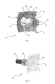
- One in the Fig. 1 to Fig. 4 shown fully or in parts, for example, designed as a taillight motor vehicle light 01 has at least one reflector 02 and at least one lamp 03 with at least one light source 04.
- the at least one reflector 02 together with the at least one light source 03 comprising at least one light source 03 can be accommodated in a light housing enclosed by a luminaire housing, not shown in detail, and a transparent, preferably clear and colorless lens.
- At least one recess 05 is provided as a lamp hole for at least one light source 04 of the luminous means 03.
- the motor vehicle light 01 comprises a cover 06 simulating the area removed from the reflector 02 by the recess 05. At least the cover 06 is along or in the direction of a movement path at least between one in one Fig. 2 shown cold state of the motor vehicle light 01 with switched off bulbs 03 corresponding first state and a in Fig. 1 and Fig. 3 illustrated warm state of the vehicle light 01 with switched on lamp 03 corresponding second state relative to the reflector 02 movably arranged.
- the cover 06 closes the recess 05 in the reflector 02 flush with the front 07 of the reflector 02 from.
- the cover 06 corresponds to the shape of the recess 05 and in appearance and shape of the front side 07 of the reflector 02 preferably such that in the first state, the flush with the front 07 of the reflector 02 final cover 06 in the reflector 02 as such is not recognizable.
- FIG. 3 and FIG. 4 illustrated, second state, the cover 06, the recess 05 free and is located in the Fig. 1, Fig. 2 .
- FIG. 3 and FIG. 4 shown view of the front of the front 07 of the reflector 02 in front of the reflector 02 limited recess 05th
- the light source 04 projects on the front side 07 of the reflector 02 at least partially over the edge 08 of the reflector 02 bounding the recess 05 and surrounding it.
- the light source 04 is seen from behind the cover 06, seen in the hot state and in the cold state, anyway, in which the cover 06 closes the recess 05, the direct beam path of the light-facing front 07 of the reflector 02 prevents at least one light source 04 radiated light through the lens and thus denied the direct view of the light source 04.
- Fig. 4 in this case shows the same view with a view of the front 07 of the reflector 02 as Fig. 3 , wherein the cover 06 is removed for clarity, in order to explain the construction of the motor vehicle light 01 view on or behind the cover 06 arranged there mechanically fixed and electrically contacted light sources 04 of a lamp 03 of the vehicle lamp 01 free.
- the movement path may extend at least in sections along a straight line comprising a local surface normal of a surface formed by the recess 06.
- the trajectory is a distance along a local surface normal of a surface formed by the recess 06 comprehensive straights.
- the cover 06 may be formed corresponding to the recess 05.
- the cover 06 as in Fig. 1 represented the recess 05 in the form, function and appearance of the reflector 02 simulate. This is in the in Fig. 2 illustrated first state neither the recess 05, nor the cover 06 recognizable. For the viewer, the impression of a completely homogeneous, lamp hole and light source-free reflector 02 results.
- the cover 06 can in in Fig. 2 illustrated, the cold state corresponding first state, the recess 05 cover in two ways.
- the cover 06 Apart from required tolerances and gaps, which are necessary that the cover 06 can retract into the recess 05 to terminate flush with the front 07 of the reflector 02, while the cover 06 has a with the by the recess 05 bounding and surrounding Edge 08 of the reflector 02 formed outer contour in terms of geometry and dimensions identical shape.
- the cover 06 abut the recess 05 surrounding the reflector 02 on the front of the lens facing the lens 07 and thereby overlap the recess 05 surrounding edge 08 of the reflector 02.
- the cover does not close around the recess 05 around flush with the front 07 of the reflector 02 from.
- For the production is simplified because the overlapping allows tolerance compensation.
- the cover 06 may be arranged to be movable together with the light source 04 or independently thereof in the direction of the movement path relative to the reflector 02.
- the light source 04 can be mechanically fastened to the cover 06 and arranged in an electrically contacted manner, so that only a facial expression is required for the relative movement between reflector 02 and cover 06.
- the motor vehicle light 01 can also, as in Fig. 3 represented a primary reflector 09 include.
- the primary reflector 09 is arranged to be movable together with the cover 06 and the light source 04 relative to the reflector 02.
- the light source 04 is arranged between the cover 06 and the primary reflector 09.
- the primary reflector 09 either ends flush with the reflector 02 surrounding the recess 05 or its front side 07, or lies against the rear side 10 facing away from the recess 05 and overlaps the recess 05 surrounding it Edge 08 of the reflector 02.
- the primary reflector 09 directs the light emitted by the light source 04 in one or more desired directions, so that optionally by multiple reflection on the primary reflector 09, optionally provided on the back 11 of the cover 06 secondary reflector and the recess 05 surrounding Reflector 02 a radiation characteristic is obtained at the exit from the lens, which complies with the legal requirements for a light function of the motor vehicle light 01 with respect to luminance distribution in one or more preferred directions.
- a provided on the back 11 of the cover 06, for example there, emitted by the light source 04 light in the recess 05 surrounding reflector 02 reflective secondary reflector can be arranged on the back 11 of the cover 06, for example, or formed there.
- At least one LED 12 may be as in Fig. 4 represented as at least one light source 04 may be provided at least one lamp 03 of the motor vehicle light 01.
- LEDs 12 as light sources 04 can be dispensed with a color filter by a colored lens, as required for example in incandescent lamps.
- LEDs 12 When using LEDs 12, such a coloring of the lens is not required. As a result, with the use of LEDs 12 and colorless lenses are used because no color filtering is required. In this case, costs can be saved at the same time, as can be completely dispensed with the red cycle during plastic injection of the lens.
- several identical or different colored LEDs 12 as light sources 04 of a lamp 03 be provided, for example, to bring several light functions, for example, different brightness and / or different color in one and the same lamp chamber of the motor vehicle light 01 under.
- the cover 06 may as in Fig. 3 shown on its front side facing the lens 13 may be provided with at least one graphic 14.
- the graphic 14 may be raised or recessed in a relief-like manner or flush-mounted in the front side 13 of the cover 06.
- the graphic 14 can be one or more images and / or drawings and / or graphic representations and / or logos and / or characters, such as letters and / or numbers, etc., or one or more combinations thereof, such as for example, a brand emblem, to enumerate only a few conceivable embodiments of graphics.
- the cover 06 may as in Fig. 2 illustrated comprise a web 15 which may correspond to a corresponding portion 16 of the recess 05.
- the web 15 may serve the movable arrangement of the cover 06, for example by attachment to a movement along the trajectory mimic.
- the web 15 of the lamination can be used for any intended electrical contacting of the light source 04 of a lamp 03, such as provided as light sources 04 and mechanically attached to the cover and electrically contacted LEDs 12.
- the web 15 is not shown for clarity, as well as in Fig. 4 in which the entire cover 06 is not shown in order to show the LEDs 12 provided there as light sources 04.
- a motor vehicle light 01 described above can be subdivided into one or more lamp chambers, of which at least one lamp chamber has a previously described reflector 02 together with a cover 06 which is movably arranged relative to this.
- the invention is particularly industrially applicable in the field of production of motor vehicle lights.
Landscapes
- Engineering & Computer Science (AREA)
- General Engineering & Computer Science (AREA)
- Physics & Mathematics (AREA)
- Microelectronics & Electronic Packaging (AREA)
- Optics & Photonics (AREA)
- Mechanical Engineering (AREA)
- Non-Portable Lighting Devices Or Systems Thereof (AREA)
Priority Applications (1)
| Application Number | Priority Date | Filing Date | Title |
|---|---|---|---|
| EP11187438.4A EP2589859A1 (fr) | 2011-11-02 | 2011-11-02 | Lampe de véhicule automobile |
Applications Claiming Priority (1)
| Application Number | Priority Date | Filing Date | Title |
|---|---|---|---|
| EP11187438.4A EP2589859A1 (fr) | 2011-11-02 | 2011-11-02 | Lampe de véhicule automobile |
Publications (1)
| Publication Number | Publication Date |
|---|---|
| EP2589859A1 true EP2589859A1 (fr) | 2013-05-08 |
Family
ID=45218218
Family Applications (1)
| Application Number | Title | Priority Date | Filing Date |
|---|---|---|---|
| EP11187438.4A Withdrawn EP2589859A1 (fr) | 2011-11-02 | 2011-11-02 | Lampe de véhicule automobile |
Country Status (1)
| Country | Link |
|---|---|
| EP (1) | EP2589859A1 (fr) |
Cited By (5)
| Publication number | Priority date | Publication date | Assignee | Title |
|---|---|---|---|---|
| FR3048486A1 (fr) * | 2016-03-04 | 2017-09-08 | Peugeot Citroen Automobiles Sa | Bloc optique pour vehicule automobile comportant un dispositif lumineux entierement dissimulable. |
| US11155202B2 (en) | 2020-01-29 | 2021-10-26 | Volkswagen Aktiengesellschaft | Vehicle having a rear light having a screen with tab with visible markings |
| FR3117574A1 (fr) * | 2020-12-15 | 2022-06-17 | Valeo Vision | Indication lumineuse de la position d’un élément d’obturation d’un cadre |
| EP4339022A1 (fr) * | 2022-09-16 | 2024-03-20 | Magna Exteriors GmbH | Pièce de garniture pour un véhicule automobile |
| WO2024094371A1 (fr) * | 2022-10-31 | 2024-05-10 | Mercedes-Benz Group AG | Ensemble habillage extérieur pour véhicule à moteur et véhicule à moteur comprenant un tel ensemble habillage extérieur |
Citations (7)
| Publication number | Priority date | Publication date | Assignee | Title |
|---|---|---|---|---|
| DE494589C (de) * | 1926-08-14 | 1930-03-25 | David Edward William Rees | Abblendbarer Scheinwerfer |
| GB364005A (en) * | 1930-08-25 | 1931-12-28 | David Temple Phillips | Fog penetrator and dimming device for lamps |
| DE10015759A1 (de) | 2000-03-30 | 2001-10-11 | Sidler Gmbh & Co | Kraftfahrzeugleuchte mit indirektem Innenlicht |
| EP1298382A1 (fr) * | 2001-09-28 | 2003-04-02 | Osram-Sylvania Inc. | Ampoule à DEL remplacable avec élément optique interchangeable |
| US6789929B1 (en) * | 2002-09-11 | 2004-09-14 | Dj Auto Components Corp. | Lamp structure |
| FR2858682A1 (fr) * | 2003-08-07 | 2005-02-11 | Schefenacker Vision Systems | Unite d'eclairage comportant une source lumineuse et un conducteur de lumiere |
| EP1962012A2 (fr) * | 2007-02-26 | 2008-08-27 | Odelo GmbH | Eclairage pour véhicules, en particulier pour véhicules automobiles |
-
2011
- 2011-11-02 EP EP11187438.4A patent/EP2589859A1/fr not_active Withdrawn
Patent Citations (7)
| Publication number | Priority date | Publication date | Assignee | Title |
|---|---|---|---|---|
| DE494589C (de) * | 1926-08-14 | 1930-03-25 | David Edward William Rees | Abblendbarer Scheinwerfer |
| GB364005A (en) * | 1930-08-25 | 1931-12-28 | David Temple Phillips | Fog penetrator and dimming device for lamps |
| DE10015759A1 (de) | 2000-03-30 | 2001-10-11 | Sidler Gmbh & Co | Kraftfahrzeugleuchte mit indirektem Innenlicht |
| EP1298382A1 (fr) * | 2001-09-28 | 2003-04-02 | Osram-Sylvania Inc. | Ampoule à DEL remplacable avec élément optique interchangeable |
| US6789929B1 (en) * | 2002-09-11 | 2004-09-14 | Dj Auto Components Corp. | Lamp structure |
| FR2858682A1 (fr) * | 2003-08-07 | 2005-02-11 | Schefenacker Vision Systems | Unite d'eclairage comportant une source lumineuse et un conducteur de lumiere |
| EP1962012A2 (fr) * | 2007-02-26 | 2008-08-27 | Odelo GmbH | Eclairage pour véhicules, en particulier pour véhicules automobiles |
Cited By (7)
| Publication number | Priority date | Publication date | Assignee | Title |
|---|---|---|---|---|
| FR3048486A1 (fr) * | 2016-03-04 | 2017-09-08 | Peugeot Citroen Automobiles Sa | Bloc optique pour vehicule automobile comportant un dispositif lumineux entierement dissimulable. |
| US11155202B2 (en) | 2020-01-29 | 2021-10-26 | Volkswagen Aktiengesellschaft | Vehicle having a rear light having a screen with tab with visible markings |
| FR3117574A1 (fr) * | 2020-12-15 | 2022-06-17 | Valeo Vision | Indication lumineuse de la position d’un élément d’obturation d’un cadre |
| WO2022128865A1 (fr) * | 2020-12-15 | 2022-06-23 | Valeo Vision | Indication lumineuse de la position d'un élément d'obturation d'un cadre |
| EP4339022A1 (fr) * | 2022-09-16 | 2024-03-20 | Magna Exteriors GmbH | Pièce de garniture pour un véhicule automobile |
| US11999303B2 (en) | 2022-09-16 | 2024-06-04 | Magna Exteriors Gmbh | Cladding part for a motor vehicle |
| WO2024094371A1 (fr) * | 2022-10-31 | 2024-05-10 | Mercedes-Benz Group AG | Ensemble habillage extérieur pour véhicule à moteur et véhicule à moteur comprenant un tel ensemble habillage extérieur |
Similar Documents
| Publication | Publication Date | Title |
|---|---|---|
| EP2584249B1 (fr) | Conducteur lumineux et lampe de véhicule automobile | |
| AT517394B1 (de) | Beleuchtungseinrichtung für ein Kraftfahrzeug mit lumineszierenden Elementen | |
| DE102015115128A1 (de) | Beleuchtungsvorrichtung für Fahrzeuge | |
| DE102005040100B4 (de) | Fahrzeugleuchte mit einem ersten Leuchtenfunktionsbereich und wenigstens einem weiteren Leuchtenfunktionsbereich in Trennbereichen zwischen durchleuchtbaren, lichtstreuende Mittel aufweisenden Leuchtkörpern für den ersten Leuchtenfunktionsbereich | |
| DE102014211874A1 (de) | Beleuchtungseinrichtung eines Kraftfahrzeugs | |
| DE102014205996A1 (de) | Fahrzeug-Richtungsanzeiger-Leuchte | |
| EP3355664A1 (fr) | Ampoule ayant un élément fluorescent et filtre de couleur et ampoule en étant équipé | |
| DE102011014923A1 (de) | Fahrzeugleuchte zur Beleuchtung des Innenraums des Fahrzeugs | |
| DE202017001946U1 (de) | Scheinwerfer mit einem optischen System mit statischem Matrix-Abbiegelicht | |
| DE102017127663A1 (de) | Leuchtvorrichtung, insbesondere eine Signalleuchte für Kraftfahrzeuge | |
| EP2589859A1 (fr) | Lampe de véhicule automobile | |
| DE102012024625A1 (de) | Kraftfahrzeugleuchtenanordnung | |
| DE102007033706B4 (de) | Fahrzeugleuchtvorrichtung mit einer dreidimensionalen mehrfarbigen Zwischenlichtscheibe | |
| DE102009053571B4 (de) | Leuchte für Kraftfahrzeuge mit einem Spiegelsystem und einem Lichtleiter | |
| DE102012111313A1 (de) | Beleuchtungseinheit für ein Kraftfahrzeug | |
| DE102011053805A1 (de) | LED-Leuchte insbesondere für Schienenfahrzeuge, insbesondere LED-Leuchte zur Verwendung als Signalleuchte und/oder Scheinwerfer, sowie optisches Bauelement für LED-Signalleuchten und LED-Scheinwerfer | |
| DE102014203245A1 (de) | Beleuchtungseinrichtung eines Kraftfahrzeugs | |
| DE102018220623A1 (de) | Leuchtenanordnung für ein Fahrzeug | |
| DE102015204747A1 (de) | Beleuchtungseinrichtung für ein Kraftfahrzeug | |
| DE102015121324A1 (de) | Leuchtvorrichtung für ein Kraftfahrzeug | |
| DE102011104055A1 (de) | Leuchteinrichtung für ein Fahrzeug | |
| EP2955063A1 (fr) | Lampe de véhicule automobile | |
| EP2722578A1 (fr) | Élément de conducteur lumineux en surface, moyen d'éclairage et lampe de véhicule automobile | |
| EP2650707A1 (fr) | Moyen d'éclairage et lampe de véhicule automobile | |
| DE102015108486A1 (de) | Seitenblinkleuchte für Fahrzeuge |
Legal Events
| Date | Code | Title | Description |
|---|---|---|---|
| PUAI | Public reference made under article 153(3) epc to a published international application that has entered the european phase |
Free format text: ORIGINAL CODE: 0009012 |
|
| 17P | Request for examination filed |
Effective date: 20120605 |
|
| AK | Designated contracting states |
Kind code of ref document: A1 Designated state(s): AL AT BE BG CH CY CZ DE DK EE ES FI FR GB GR HR HU IE IS IT LI LT LU LV MC MK MT NL NO PL PT RO RS SE SI SK SM TR |
|
| AX | Request for extension of the european patent |
Extension state: BA ME |
|
| RIC1 | Information provided on ipc code assigned before grant |
Ipc: B60Q 1/26 20060101ALI20131125BHEP Ipc: F21V 14/02 20060101AFI20131125BHEP Ipc: F21S 8/10 20060101ALI20131125BHEP |
|
| GRAP | Despatch of communication of intention to grant a patent |
Free format text: ORIGINAL CODE: EPIDOSNIGR1 |
|
| INTG | Intention to grant announced |
Effective date: 20140212 |
|
| STAA | Information on the status of an ep patent application or granted ep patent |
Free format text: STATUS: THE APPLICATION IS DEEMED TO BE WITHDRAWN |
|
| 18D | Application deemed to be withdrawn |
Effective date: 20140624 |