EP2589453A2 - Verarbeitungszustandseinstellvorrichtung für eine Vorrichtung zur Funkenerosion - Google Patents
Verarbeitungszustandseinstellvorrichtung für eine Vorrichtung zur Funkenerosion Download PDFInfo
- Publication number
- EP2589453A2 EP2589453A2 EP12175653.0A EP12175653A EP2589453A2 EP 2589453 A2 EP2589453 A2 EP 2589453A2 EP 12175653 A EP12175653 A EP 12175653A EP 2589453 A2 EP2589453 A2 EP 2589453A2
- Authority
- EP
- European Patent Office
- Prior art keywords
- machining
- condition
- unsatisfactory
- machining condition
- state
- Prior art date
- Legal status (The legal status is an assumption and is not a legal conclusion. Google has not performed a legal analysis and makes no representation as to the accuracy of the status listed.)
- Granted
Links
Images




Classifications
-
- B—PERFORMING OPERATIONS; TRANSPORTING
- B23—MACHINE TOOLS; METAL-WORKING NOT OTHERWISE PROVIDED FOR
- B23H—WORKING OF METAL BY THE ACTION OF A HIGH CONCENTRATION OF ELECTRIC CURRENT ON A WORKPIECE USING AN ELECTRODE WHICH TAKES THE PLACE OF A TOOL; SUCH WORKING COMBINED WITH OTHER FORMS OF WORKING OF METAL
- B23H7/00—Processes or apparatus applicable to both electrical discharge machining and electrochemical machining
- B23H7/02—Wire-cutting
- B23H7/06—Control of the travel curve of the relative movement between electrode and workpiece
- B23H7/065—Electric circuits specially adapted therefor
-
- B—PERFORMING OPERATIONS; TRANSPORTING
- B23—MACHINE TOOLS; METAL-WORKING NOT OTHERWISE PROVIDED FOR
- B23H—WORKING OF METAL BY THE ACTION OF A HIGH CONCENTRATION OF ELECTRIC CURRENT ON A WORKPIECE USING AN ELECTRODE WHICH TAKES THE PLACE OF A TOOL; SUCH WORKING COMBINED WITH OTHER FORMS OF WORKING OF METAL
- B23H1/00—Electrical discharge machining, i.e. removing metal with a series of rapidly recurring electrical discharges between an electrode and a workpiece in the presence of a fluid dielectric
- B23H1/02—Electric circuits specially adapted therefor, e.g. power supply, control, preventing short circuits or other abnormal discharges
- B23H1/024—Detection of, and response to, abnormal gap conditions, e.g. short circuits
-
- B—PERFORMING OPERATIONS; TRANSPORTING
- B23—MACHINE TOOLS; METAL-WORKING NOT OTHERWISE PROVIDED FOR
- B23H—WORKING OF METAL BY THE ACTION OF A HIGH CONCENTRATION OF ELECTRIC CURRENT ON A WORKPIECE USING AN ELECTRODE WHICH TAKES THE PLACE OF A TOOL; SUCH WORKING COMBINED WITH OTHER FORMS OF WORKING OF METAL
- B23H7/00—Processes or apparatus applicable to both electrical discharge machining and electrochemical machining
- B23H7/14—Electric circuits specially adapted therefor, e.g. power supply
- B23H7/20—Electric circuits specially adapted therefor, e.g. power supply for program control, e.g. adaptive
Definitions
- the present invention relates to a machining condition adjusting device for electric discharge machining.
- a processing machine for industrial applications performs a machining process such that a desired final shape is obtained by applying a physical, electrical, or chemical action to a metal workpiece of, for example, tool steel, thereby gradually changing the shape of the workpiece.
- the state of this machining process can be varied by changing control parameters called a machining condition.
- the result of machining depends on the appropriateness of a selected machining condition. It is actually difficult, however, to instantaneously select an appropriate condition that meets required machining specifications. In electric discharge machining, for example, it is essential to select such a machining condition that the machining speed is high and an abnormal machining state can be avoided.
- the machining condition stated herein comprises a plurality of control parameters, each of which is selected from varying values.
- an operator settles an optimum machining condition of an electric discharge machine by frequently repeating operations including monitoring machining states, such as voltage, current, short-circuiting, disconnection, machining speed, etc., during machining on the machine side, adjusting the used machining condition based on the result of the machining and a machining state during machining, and performing machining again under the adjusted machining condition.
- machining states such as voltage, current, short-circuiting, disconnection, machining speed, etc.
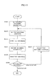
- Step SA01 information indicative of a target machining state (non-occurrence of disconnection/short-circuiting, target machining speed, etc.) is registered as required machining information (Step SA01).
- a machining condition to be used for test machining is set (Step SA02).
- the machining condition is a combination of set values of machining voltage, machining speed, current, downtime, etc., during machining.
- Step SA03 test machining is started under the machining condition set in Step SA02 (Step SA03). Thereupon, the operator monitors and records the machining state during machining on the machine side until the end of the machining, or a machining state during machining output from an electric discharge controller is automatically recorded (Step SA04).
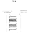
- Step SA05 After the end of the test machining (Step SA05), whether machining is satisfactory or not is determined by the result of the machining and the machining state during machining recorded automatically or by the operator (Step SA06). If the machining is then determined to be unsatisfactory, the machining condition used for the test machining is adjusted (Step SA07), and the adjusted machining condition is regarded as the one to be used for the test machining. Thereupon, the program returns to Step SA02, in which the machining condition for the test machining is reset. Thereafter, the processing of Steps SA03, SA04, SA05, SA06, SA07 and SA02 is repeated so that the machining is determined to be satisfactory in Step SA06. A simple straight-line shape and a zigzag shape shown in FIG. 14 are used for the test machining.
- Japanese Patent Application Laid-Open No. 2-153476 discloses adaptive control such that optimum machining is performed by determining the machining state during machining and varying the machining condition.
- the object of the present invention is to provide a machining condition adjusting device configured to settle an optimum machining condition by automatically monitoring machining states and adjusting a machining condition based on a machining state during machining.
- the present invention relates to a machining condition adjusting device for an electric discharge machine configured to machine a workpiece according to a set machining condition.
- the machining condition adjusting device comprises: a machining state information acquiring unit that acquires a plurality of signals or physical quantities for determining whether a machining state is satisfactory or not, as machining state information, for each predetermined period; a required machining state storage unit that stores reference values of the signals or physical quantities as reference machining state information; a machining state determination unit that compares the machining state information acquired by the machining state information acquiring unit with the reference machining state information stored by the required machining state storage unit, thereby determining whether the machining state is satisfactory or not, and to determine the type of unsatisfactory machining if the machining state is determined to be unsatisfactory; a machining condition adjustment method storage unit stored with, as a method of adjusting the machining condition to be performed to cancel the unsatisfactory machining if the machining state is determined to be unsatisfactory
- the machining condition is adjusted by changing the set items to be adjusted according to the priority of the set items if the same unsatisfactory machining is determined again by the machining state determination unit when machining is performed after the machining condition adjustment, and the acquisition of the information by the machining state information acquiring unit, determination by the machining state determination unit, and adjustment by the machining condition adjustment unit are repeatedly performed so that satisfactory machining is determined by the machining state determination unit.
- the machining condition adjustment method storage unit may be configured to allow addition of the type of unsatisfactory machining and the set items of the machining condition to be adjusted.
- the machining condition adjustment method storage unit may be configured to allow change of the priority of the type of unsatisfactory machining to adjust the machining condition for canceling the unsatisfactory machining, the priority of the set items of the machining condition to be adjusted according to the type of the unsatisfactory machining, and the adjusted values of the set items.
- a machining condition adjusting device for an electric discharge machine configured so that the best machining condition can be achieved by determining whether a machining is satisfactory or not by a machining state obtained from the discharge machine during test machining, adjusting the machining condition in case of unsatisfactory machining, based on a machining state during machining and the determination as to whether machining is satisfactory or not, and automatically repeating the test machining so that the machining becomes satisfactory, based on the adjusted machining condition.
- a determination process for a machining condition performed by a machining condition adjusting device for an electric discharge machine according to the present invention will be described with reference to the flowchart of FIG. 1 .
- the following is a sequential description of various steps of operation.
- Step SB01 Information indicative of a target machining state (indicative of non-occurrence of disconnection/short-circuiting, target machining speed, etc.) is registered as required machining information.
- Step SB02 A machining condition to be used for test machining is set.
- Step SB03 Test machining is started under the test machining condition set in Step SB02.
- Step SB04 The machining state during the test machining is automatically monitored from start to end.
- Step SB05 The machining state during the test machining is evaluated in comparison with the machining state of the required machining information, whereby whether the machining is satisfactory or not is checked.
- Step SB06 If it is determined in Step SB05 that the machining is unsatisfactory, the machining condition used in the test machining is automatically adjusted.
- Step SB07 End processing for the test machining is performed such that power supply for electric discharge is turned off, for example.
- Steps SB02 to SB06 are repeated so that the machining becomes satisfactory.
- the test machining is automatically repeated so that the machining becomes satisfactory, whereupon the best machining condition can be obtained.
- machining state indicative of unsatisfactory machining is based on the occurrence or non-occurrence of disconnection/short-circuiting and machining speed.
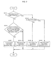
- Step SC01 The machining state required for making a machining satisfactory is compared with the machining state during machining. If disconnection or short-circuiting is caused (YES), the program proceeds to Step SC02. If not (NO), the program proceeds to Step SC03.
- Step SC02 It is determined whether or not the caused trouble is disconnection. If the trouble is disconnection (YES), the program proceeds to Step SC04. If not (NO), the program proceeds to Step SC05.
- Step SC03 Variation of the machining state during machining relative to the machining state required for making a machining satisfactory is determined on condition that neither disconnection nor short-circuiting is caused. If a certain tolerance is then exceeded by the machining speed during machining relative to the required machining speed (YES), the program proceeds to Step S06. If not (NO), the program proceeds to Step S07.
- Step SC04 Decision value "1" for unsatisfactory machining is set, whereupon the processing ends.
- Step SC05 Decision value "2" for unsatisfactory machining is set, whereupon the processing ends.
- Step SC06 Decision value "3" for unsatisfactory machining is set, whereupon the processing ends.
- Step SC07 Decision value "0" for unsatisfactory machining is set, whereupon the processing ends.
- a method of adjusting a machining condition will be described with reference to the flowchart of FIG. 3 .
- the following is a sequential description of various steps of operation.
- the machining state indicative of unsatisfactory machining is based on the occurrence or non-occurrence of disconnection/short-circuiting and machining speed.
- Step SD01 It is determined whether or not the decision value is 1 or 2 (whether machining is subjected to disconnection or short-circuiting). If the decision value is 1 or 2 (YES), the program proceeds to Step SD02. If not (NO), the program proceeds to Step SD03.
- Step SD02 It is determined whether or not the decision value is 1. If the decision value is 1 (YES), the program proceeds to Step SD05. If not (NO), the program proceeds to Step SD07.
- Step SD03 It is determined whether or not the decision value is 3. If the decision value is 3 (YES), the program proceeds to Step SD04. If not (NO), this processing ends.
- Step SD04 It is determined whether or not the machining speed during machining is higher than the required machining speed. If the machining speed during machining is higher (YES), the program proceeds to Step SD09. If not (NO), the program proceeds to Step SD11.
- Step SD05 The adjustment method ⁇ 1> is performed.
- Step SD06 The value of an index A indicative of the performed adjustment method is set to 1, whereupon this processing ends.
- Step SD07 The adjustment method ⁇ 2> is performed.
- Step SD08 The value of the index A indicative of the performed adjustment method is set to 2, whereupon this processing ends.
- Step SD09 The adjustment method ⁇ 3> is performed.
- Step SD10 The value of the index A indicative of the performed adjustment method is set to 3, whereupon this processing ends.
- Step SD11 The adjustment method ⁇ 4> is performed.
- Step SD12 The value of the index A indicative of the performed adjustment method is set to 4, whereupon this processing ends.
- the machining condition is adjusted based on the adjustment method corresponding to each machining state indicative of unsatisfactory machining.
- the priority and an adjusted value and its increase and decrease are set in the manner shown in the following Table 1, for each set item of the machining condition to be adjusted for each machining state indicative of unsatisfactory machining.
- Set items of the machining condition are adjusted according to Table 1.
- Table 1 shows only those cases where unsatisfactory machining is determined by a single piece of machining state information. Alternatively, however, the state of unsatisfactory machining may be determined by a combination of two pieces of machining state information.
- the priority of the set items is given by [1], [2], [3], ⁇ in the descending order. The highest priority is given to level [1].
- the adjustment method ⁇ 1> is a method of adjusting the machining condition for the case where the machining state indicative of unsatisfactory machining is "disconnection".
- the adjustment method ⁇ 1> will be described with reference to the flowchart of FIG. 4 . The following is a sequential description of various steps of operation.
- Step SE01 It is determined whether or not the value of the index A of the performed adjustment method is 1. If the index value is 1 (YES), the program proceeds to Step SE02. If not (NO), the program proceeds to Step SE03.
- Step SE02 The value of the set item of priority [2] is increased, whereupon this processing ends.
- Step SE03 The value of the set item of priority [1] is reduced, whereupon this processing ends.
- the occurrence of the disconnection is attributable to excessive power of each discharge pulse, so that the power should be reduced. As shown in Table 1, therefore, priority [1] is given to the power of each discharge pulse, and priority [2] is given to the length of each discharge pulse.
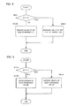
- the flowchart of FIG. 5 shows processing for the adjustment method ⁇ 1> reflective of the adjustment of the machining condition. The following is a sequential description of various steps of operation.
- Step SF01 It is determined whether or not the value of the index A of the performed adjustment method is 1. If the index value is 1 (YES), the program proceeds to Step SF02. If not (NO), the program proceeds to Step SF03.
- Step SF02 The length of each discharge pulse is extended, whereupon this processing ends.
- Step SF03 The power of each discharge pulse is reduced, whereupon this processing ends.
- the adjustment method ⁇ 2> is a method of adjusting the machining condition for the case where the machining state indicative of unsatisfactory machining is "short-circuiting". The adjustment method ⁇ 2> will be described with reference to the flowchart of FIG. 6 .
- Step SG01 The value of the set item of priority [1] is increased.
- the flowchart of FIG. 7 shows processing for the adjustment method ⁇ 2> reflective of the adjustment of the machining condition.
- Step SH01 The servo voltage is reduced, whereupon this processing ends.
- the adjustment method ⁇ 3> is a method of adjusting the machining condition for the case where the machining state indicative of unsatisfactory machining is "machining speed during machining > required machining speed".
- the adjustment method ⁇ 3> is illustrated in the flowchart of FIG. 8 . Various steps of operation will be sequentially described with reference to the flowchart of FIG. 8 .
- Step SJ01 It is determined whether or not condition 1 is satisfied. If condition 1 is satisfied (YES), the program proceeds to Step SJ02. If not (NO), the program proceeds to Step SJ05.
- Step SJ02 It is determined whether or not the value of the index A of the performed adjustment method is 3. If the index value is 3 (YES), the program proceeds to Step SJ03. If not (NO), the program proceeds to Step SJ04.
- Step SJ04 The value of the set item of priority [1] is reduced, whereupon this processing ends.
- Step SJ05 The value of the set item of priority [3] is increased, whereupon this processing ends.
- priority [1] is given to the feed speed gain
- priority [2] is given to the power of each discharge pulse
- priority [3] is given to the length of each discharge pulse.
- the flowchart of FIG. 9 shows processing for the adjustment method ⁇ 3> reflective of the adjustment of the machining condition. The following is a sequential description of various steps of operation.
- Step SK01 It is determined whether or not condition 1 is satisfied. If condition 1 is satisfied (YES), the program proceeds to Step SK02. If not (NO), the program proceeds to Step SK05.
- Step SK02 It is determined whether or not the value of the index A of the performed adjustment method is 3. If the index value is 3 (YES), the program proceeds to Step SK03. If not (NO), the program proceeds to Step SK04.
- Step SK03 The power of each discharge pulse is reduced, whereupon this processing ends.
- Step SK04 The feed speed gain is reduced, whereupon this processing ends.
- Step SK05 The length of each discharge pulse is extended, whereupon this processing ends.
- the adjustment method ⁇ 4> is a method of adjusting the machining condition for the case where the machining state indicative of unsatisfactory machining is "machining speed during machining ⁇ required machining speed".
- the adjustment method ⁇ 4> will be described with reference to the flowchart of FIG. 10 . The following is a sequential description of various steps of operation.
- Step SL01 It is determined whether or not condition 2 is satisfied. If condition 2 is satisfied (YES), the program proceeds to Step SL02. If not (NO), the program proceeds to Step SL05.
- Step SL02 It is determined whether or not the value of the index A of the performed adjustment method is 4. If the index value is 4 (YES), the program proceeds to Step SL03. If not (NO), the program proceeds to Step SL04.
- Step SL03 The value of the set item of priority [2] is increased, whereupon this processing ends.
- Step SL04 The value of the set item of priority [1] is increased, whereupon this processing ends.
- Step SL05 The value of the set item of priority [3] is reduced, whereupon this processing ends.
- priority [1] is given to the feed speed gain
- priority [2] is given to the power of each discharge pulse
- priority [3] is given to the length of each discharge pulse.
- the flowchart of FIG. 11 shows processing for the adjustment method ⁇ 3> reflective of the adjustment of the machining condition. The following is a sequential description of various steps of operation.
- Step SM01 It is determined whether or not condition 2 is satisfied. If condition 2 is satisfied (YES), the program proceeds to Step SM02. If not (NO), the program proceeds to Step SM05.
- Step SM02 It is determined whether or not the value of the index A of the performed adjustment method is 4. If the index value is 4 (YES), the program proceeds to Step SM03. If not (NO), the program proceeds to Step SM04.
- Step SM03 The power of each discharge pulse is increased, whereupon this processing ends.
- Step SM04 The feed speed gain is increased, whereupon this processing ends.
- Step SM05 The length of each discharge pulse is reduced, whereupon this processing ends.
- connection In connection with the above examples, "disconnection”, “short-circuiting”, “machining speed during machining > required machining speed”, and “machining speed during machining ⁇ required machining speed” have been described as unsatisfactory machining states.
- machining states for the determination of other unsatisfactory machining such as a combination of the aforementioned machining states indicative of unsatisfactory machining, machining voltage, etc., can be added.
- no-load voltage, working fluid volume, etc. may be added besides the servo voltage, length of each discharge pulse, power of each discharge pulse, and feed speed gain described in connection with the above examples.
- FIG. 12 is a block diagram illustrating one embodiment of the machining condition adjusting device for an electric discharge machine according to the present invention.
- a required machining state storage unit 18 is loaded with a machining state required for making a test machining satisfactory.
- a machining condition adjustment method storage unit 12 stores a machining condition adjustment method for the case where unsatisfactory machining is caused during test machining.
- a machining state information acquiring unit 22 acquires a plurality of signals or physical quantities for determining whether the machining state is satisfactory or not, as machining state information during test machining, for each predetermined period.
- a machining state determination unit 20 compares the machining state during machining acquired by the machining state information acquiring unit 22 with the machining state required for making a test machining satisfactory, thereby determining whether the test machining is satisfactory or not.
- a machining condition adjustment unit 14 adjusts the machining condition for test machining so that the machining state during machining agrees with the machining state required for making a test machining satisfactory, based on the machining condition adjustment method, if unsatisfactory machining is determined by the machining state determination unit 20.
- the acquisition of the machining state during machining by the machining state information acquiring unit 22, comparison of the machining state during machining with the required machining state and determination as to whether the test machining is satisfactory or not by the machining state determination unit 20, and adjustment of the machining condition for test machining by the machining condition adjustment unit 14 are repeatedly performed so that satisfactory machining is determined by the machining state determination unit 20.
- the required machining state storage unit 18 is previously stored with the machining state required for test machining, such as the occurrence or non-occurrence of disconnection, target machining speed, etc., by an operator.
- the machining condition adjustment method storage unit 12 is previously stored with the machining condition adjustment method for the case where unsatisfactory machining is caused during test machining by the operator.
- the machining condition adjustment method is represented by the priority of the set items of the machining condition to be adjusted for each machining state indicative of unsatisfactory machining. Further, the priority can be arbitrarily changed, and the type of the machining state indicative of unsatisfactory machining and the set items of the machining condition to be adjusted can be arbitrarily added. Thus, satisfactory machining can be achieved on each occasion by appropriately selecting adjustment methods corresponding to various required machining states.
- the machining state information acquiring unit 22 continues to acquire the machining state during machining until the end of the test machining. If the machining state required for making a test machining satisfactory agrees with the machining state during machining acquired by the information acquiring unit 22 or is within a certain tolerance, the machining state determination unit 20 determines the machining to be satisfactory. If not, the determination unit 20 determines the machining to be unsatisfactory.
- the values of the set items of the machining condition are adjusted so that the machining state during machining agrees with the required machining state or is within the certain tolerance, based on the machining condition adjustment method.
- the test machining is continued using the adjusted machining condition.
- An optimum machining condition can be obtained by repeating the machining condition adjustment in this manner.
- the machining condition adjustment method storage unit 12 may alternatively be configured so as to allow addition of the type of the machining state and the set items of the machining condition to be adjusted.
- the storage unit 12 may be configured to allow change of the priority of the type of unsatisfactory machining to adjust the machining condition for canceling the unsatisfactory machining, the priority of the set items of the machining condition to be adjusted according to the type of the unsatisfactory machining, and the adjusted values of the set items.
- machining condition adjusting device for an electric discharge machine has been described as an external device independent of a discharge device, the same effect can also be achieved by mounting the machining condition adjusting device on the discharge device.
- the best machining condition can be achieved by determining whether the machining is satisfactory or not by the machining state obtained from the electric discharge machine during test machining, adjusting the machining condition in case of unsatisfactory machining, based on the determination as to whether the machining is satisfactory or not and the machining state, and automatically repeating the test machining by the electric discharge machine so that the machining becomes satisfactory, based on the adjusted machining condition.
- the machining condition adjusting device for an electric discharge machine of the present invention moreover, the machining condition can be automatically adjusted. Since one optimum machining condition can be settled, optimum machining can be achieved with a reproducible result by using this machining condition. Since the machining condition adjustment method can be changed, moreover, a novel adjustment method for satisfactory machining, if any, can be easily used for this purpose.
Landscapes
- Engineering & Computer Science (AREA)
- Mechanical Engineering (AREA)
- Chemical & Material Sciences (AREA)
- Chemical Kinetics & Catalysis (AREA)
- Electrochemistry (AREA)
- Automation & Control Theory (AREA)
- Electrical Discharge Machining, Electrochemical Machining, And Combined Machining (AREA)
Applications Claiming Priority (1)
| Application Number | Priority Date | Filing Date | Title |
|---|---|---|---|
| JP2011242762A JP5199440B1 (ja) | 2011-11-04 | 2011-11-04 | 放電加工機の加工条件調整装置 |
Publications (3)
| Publication Number | Publication Date |
|---|---|
| EP2589453A2 true EP2589453A2 (de) | 2013-05-08 |
| EP2589453A3 EP2589453A3 (de) | 2014-05-07 |
| EP2589453B1 EP2589453B1 (de) | 2017-09-06 |
Family
ID=46939465
Family Applications (1)
| Application Number | Title | Priority Date | Filing Date |
|---|---|---|---|
| EP12175653.0A Active EP2589453B1 (de) | 2011-11-04 | 2012-07-10 | Verarbeitungszustandseinstellvorrichtung für eine Vorrichtung zur Funkenerosion |
Country Status (4)
| Country | Link |
|---|---|
| US (1) | US8729420B2 (de) |
| EP (1) | EP2589453B1 (de) |
| JP (1) | JP5199440B1 (de) |
| CN (1) | CN103084681B (de) |
Cited By (1)
| Publication number | Priority date | Publication date | Assignee | Title |
|---|---|---|---|---|
| EP3581311A1 (de) * | 2018-06-15 | 2019-12-18 | Fanuc Corporation | Drahtfunkenerodiermaschine und bearbeitungszustandanpassungsverfahren |
Families Citing this family (8)
| Publication number | Priority date | Publication date | Assignee | Title |
|---|---|---|---|---|
| CN103962659B (zh) * | 2014-05-13 | 2017-02-15 | 东莞华中科技大学制造工程研究院 | 一种电火花加工控制方法 |
| JP6360002B2 (ja) * | 2015-05-26 | 2018-07-18 | ファナック株式会社 | 加工データと加工結果を管理する数値制御装置 |
| JP2017030067A (ja) * | 2015-07-30 | 2017-02-09 | ファナック株式会社 | 加工時間測定機能とオンマシン測定機能を有する制御装置付き加工装置 |
| JP6063013B1 (ja) * | 2015-08-27 | 2017-01-18 | ファナック株式会社 | びびり或いは工具摩耗/破損の発生を抑制する加工条件調整機能を有する数値制御装置 |
| JP6453919B2 (ja) * | 2017-01-26 | 2019-01-16 | ファナック株式会社 | 行動情報学習装置、行動情報最適化システム及び行動情報学習プログラム |
| JP6663538B1 (ja) * | 2018-04-17 | 2020-03-11 | 三菱電機株式会社 | 機械学習装置 |
| EP3711886A1 (de) * | 2019-03-22 | 2020-09-23 | Agie Charmilles SA | Drahterosionsbearbeitungsverfahren |
| CN117042905B (zh) * | 2021-03-29 | 2025-08-15 | 发那科株式会社 | 加工条件调整装置 |
Citations (1)
| Publication number | Priority date | Publication date | Assignee | Title |
|---|---|---|---|---|
| JPH02153476A (ja) | 1988-12-06 | 1990-06-13 | Mitsubishi Electric Corp | 放電加工における加工条件設定装置 |
Family Cites Families (15)
| Publication number | Priority date | Publication date | Assignee | Title |
|---|---|---|---|---|
| US3873816A (en) * | 1968-12-27 | 1975-03-25 | Agency Ind Science Techn | Automatic adaptive controller |
| US3705286A (en) * | 1971-01-21 | 1972-12-05 | Iwao Kondo | Electric discharge machining device |
| GB2041574B (en) * | 1978-12-08 | 1983-03-09 | Inoue Japax Res | Microprocessor - controlled edm method and apparatus |
| JP2567262B2 (ja) * | 1987-11-16 | 1996-12-25 | ファナック株式会社 | ワイヤ放電加工機の加工条件検出方法及び装置 |
| JP2770184B2 (ja) * | 1989-03-31 | 1998-06-25 | 三菱電機株式会社 | 放電加工機の制御装置 |
| WO1992000826A1 (fr) * | 1990-07-13 | 1992-01-23 | Sodick Co., Ltd. | Procede et appareil de generation d'impulsions |
| JPH04122524A (ja) | 1990-09-13 | 1992-04-23 | Fanuc Ltd | 加工条件自動検索制御方式 |
| JPH068054A (ja) * | 1992-06-25 | 1994-01-18 | Fanuc Ltd | ワイヤカット放電加工機の放電加工モニタ方法 |
| JPH0691435A (ja) * | 1992-07-31 | 1994-04-05 | Fanuc Ltd | 放電加工機及び放電加工方法 |
| JP3231521B2 (ja) * | 1993-10-21 | 2001-11-26 | 株式会社ソディック | 放電加工の加工設定データ決定装置と方法 |
| JP3528400B2 (ja) * | 1996-03-05 | 2004-05-17 | 三菱電機株式会社 | 放電加工装置および放電加工方法 |
| JP4137384B2 (ja) * | 1998-12-02 | 2008-08-20 | 三菱電機株式会社 | 放電加工機の加工状態良否判定装置 |
| TW541218B (en) * | 2000-10-27 | 2003-07-11 | Mitsubishi Electric Corp | Wire electrical discharge machining device |
| JP2007069330A (ja) * | 2005-09-08 | 2007-03-22 | Fanuc Ltd | 放電加工装置の加工条件設定方法 |
| JP4795282B2 (ja) * | 2006-07-11 | 2011-10-19 | 三菱電機株式会社 | 加工条件探索装置 |
-
2011
- 2011-11-04 JP JP2011242762A patent/JP5199440B1/ja not_active Expired - Fee Related
-
2012
- 2012-07-10 EP EP12175653.0A patent/EP2589453B1/de active Active
- 2012-07-14 US US13/549,432 patent/US8729420B2/en active Active
- 2012-11-01 CN CN201210431935.6A patent/CN103084681B/zh not_active Expired - Fee Related
Patent Citations (1)
| Publication number | Priority date | Publication date | Assignee | Title |
|---|---|---|---|---|
| JPH02153476A (ja) | 1988-12-06 | 1990-06-13 | Mitsubishi Electric Corp | 放電加工における加工条件設定装置 |
Cited By (2)
| Publication number | Priority date | Publication date | Assignee | Title |
|---|---|---|---|---|
| EP3581311A1 (de) * | 2018-06-15 | 2019-12-18 | Fanuc Corporation | Drahtfunkenerodiermaschine und bearbeitungszustandanpassungsverfahren |
| US11033975B2 (en) | 2018-06-15 | 2021-06-15 | Fanuc Corporation | Wire electrical discharge machine and machining condition adjustment method |
Also Published As
| Publication number | Publication date |
|---|---|
| CN103084681A (zh) | 2013-05-08 |
| JP5199440B1 (ja) | 2013-05-15 |
| US20130112658A1 (en) | 2013-05-09 |
| EP2589453B1 (de) | 2017-09-06 |
| US8729420B2 (en) | 2014-05-20 |
| JP2013094940A (ja) | 2013-05-20 |
| CN103084681B (zh) | 2014-08-27 |
| EP2589453A3 (de) | 2014-05-07 |
Similar Documents
| Publication | Publication Date | Title |
|---|---|---|
| EP2589453A2 (de) | Verarbeitungszustandseinstellvorrichtung für eine Vorrichtung zur Funkenerosion | |
| JP6105650B2 (ja) | 機械の負荷を低減する数値制御装置 | |
| CN105629887B (zh) | 控制具有切削条件变更功能的机床的控制装置 | |
| CN107300893B (zh) | 数值控制装置 | |
| JP6404863B2 (ja) | 加減速フィルタの時定数を動的に切り替える数値制御装置 | |
| EP2532464B1 (de) | Verfahren zum Betreiben einer Drahterodiermaschine zur Herstellung von Schrägen durch Neigen des Werkstücks | |
| EP1462202B1 (de) | Steuerung für Drahtfunkenerosionsbearbeitungsmaschine | |
| EP1652610A2 (de) | Steuerung für Drahtschneidefunkenerosionsmaschine | |
| KR101980416B1 (ko) | 임의의 퇴피 위치로부터 방전 상태에서 이동시켜 중단 위치로 복귀하는 기능을 갖는 와이어 방전 가공기 | |
| JP2017072912A (ja) | 加工エリアの大きさによるパラメータの自動選定機能を有する数値制御装置 | |
| EP2617506B1 (de) | Drahterodiermaschine, die eine elektrische Drahterodierbearbeitung durch eine sich neigende Drahtelektrode ausführt | |
| EP2642361A2 (de) | Anzeigevorrichtung für Informationen über den Status der Maschinenverarbeitung | |
| CN103785903A (zh) | 具备螺纹切削循环功能的数值控制装置 | |
| JP2017097701A (ja) | 主軸負荷により送り速度を制御する数値制御装置 | |
| Hoang et al. | Modelling surface finish in electrical discharge machining tablet shape punches using response surface methodology | |
| EP0343255B1 (de) | Verfahren zum nachweis der arbeitsbedingungen einer drahtfunkenerosionsvorrichtung | |
| JP5715189B2 (ja) | オーバライドの変化時に送り速度を円滑に変更する機能を有する数値制御装置 | |
| JP4569973B2 (ja) | 放電加工装置及び方法、並びに放電発生を判別する方法 | |
| CN104281445B (zh) | 能够指定程序执行步调的动作控制器 | |
| CN105911961A (zh) | 进行抑制位置偏差过大的速度控制的数值控制装置 | |
| JP5850894B2 (ja) | テーパ加工を行うワイヤ放電加工機を制御する数値制御装置 | |
| Lee et al. | Adaptive control of the WEDM process using a self-tuning fuzzy logic algorithm with grey prediction | |
| CN106483935A (zh) | 数值控制装置 | |
| Mohapatra et al. | Experimental investigation of wire EDM parameters for gear cutting process using desirability with PCA | |
| EP3189919B1 (de) | Verfahren zur verschleisserkennung des pulsstromkabels einer drahterodiermaschine |
Legal Events
| Date | Code | Title | Description |
|---|---|---|---|
| PUAI | Public reference made under article 153(3) epc to a published international application that has entered the european phase |
Free format text: ORIGINAL CODE: 0009012 |
|
| AK | Designated contracting states |
Kind code of ref document: A2 Designated state(s): AL AT BE BG CH CY CZ DE DK EE ES FI FR GB GR HR HU IE IS IT LI LT LU LV MC MK MT NL NO PL PT RO RS SE SI SK SM TR |
|
| AX | Request for extension of the european patent |
Extension state: BA ME |
|
| PUAL | Search report despatched |
Free format text: ORIGINAL CODE: 0009013 |
|
| AK | Designated contracting states |
Kind code of ref document: A3 Designated state(s): AL AT BE BG CH CY CZ DE DK EE ES FI FR GB GR HR HU IE IS IT LI LT LU LV MC MK MT NL NO PL PT RO RS SE SI SK SM TR |
|
| AX | Request for extension of the european patent |
Extension state: BA ME |
|
| RIC1 | Information provided on ipc code assigned before grant |
Ipc: B23H 7/20 20060101ALI20140331BHEP Ipc: B23H 7/06 20060101AFI20140331BHEP Ipc: B23H 1/02 20060101ALI20140331BHEP |
|
| 17P | Request for examination filed |
Effective date: 20141103 |
|
| RBV | Designated contracting states (corrected) |
Designated state(s): AL AT BE BG CH CY CZ DE DK EE ES FI FR GB GR HR HU IE IS IT LI LT LU LV MC MK MT NL NO PL PT RO RS SE SI SK SM TR |
|
| 17Q | First examination report despatched |
Effective date: 20151221 |
|
| GRAP | Despatch of communication of intention to grant a patent |
Free format text: ORIGINAL CODE: EPIDOSNIGR1 |
|
| INTG | Intention to grant announced |
Effective date: 20170421 |
|
| GRAS | Grant fee paid |
Free format text: ORIGINAL CODE: EPIDOSNIGR3 |
|
| GRAA | (expected) grant |
Free format text: ORIGINAL CODE: 0009210 |
|
| AK | Designated contracting states |
Kind code of ref document: B1 Designated state(s): AL AT BE BG CH CY CZ DE DK EE ES FI FR GB GR HR HU IE IS IT LI LT LU LV MC MK MT NL NO PL PT RO RS SE SI SK SM TR |
|
| REG | Reference to a national code |
Ref country code: GB Ref legal event code: FG4D |
|
| REG | Reference to a national code |
Ref country code: CH Ref legal event code: EP Ref country code: AT Ref legal event code: REF Ref document number: 925329 Country of ref document: AT Kind code of ref document: T Effective date: 20170915 |
|
| REG | Reference to a national code |
Ref country code: IE Ref legal event code: FG4D |
|
| REG | Reference to a national code |
Ref country code: DE Ref legal event code: R096 Ref document number: 602012036852 Country of ref document: DE |
|
| REG | Reference to a national code |
Ref country code: CH Ref legal event code: NV Representative=s name: DR. LUSUARDI AG, CH |
|
| REG | Reference to a national code |
Ref country code: NL Ref legal event code: MP Effective date: 20170906 |
|
| REG | Reference to a national code |
Ref country code: LT Ref legal event code: MG4D |
|
| PG25 | Lapsed in a contracting state [announced via postgrant information from national office to epo] |
Ref country code: FI Free format text: LAPSE BECAUSE OF FAILURE TO SUBMIT A TRANSLATION OF THE DESCRIPTION OR TO PAY THE FEE WITHIN THE PRESCRIBED TIME-LIMIT Effective date: 20170906 Ref country code: SE Free format text: LAPSE BECAUSE OF FAILURE TO SUBMIT A TRANSLATION OF THE DESCRIPTION OR TO PAY THE FEE WITHIN THE PRESCRIBED TIME-LIMIT Effective date: 20170906 Ref country code: LT Free format text: LAPSE BECAUSE OF FAILURE TO SUBMIT A TRANSLATION OF THE DESCRIPTION OR TO PAY THE FEE WITHIN THE PRESCRIBED TIME-LIMIT Effective date: 20170906 Ref country code: NO Free format text: LAPSE BECAUSE OF FAILURE TO SUBMIT A TRANSLATION OF THE DESCRIPTION OR TO PAY THE FEE WITHIN THE PRESCRIBED TIME-LIMIT Effective date: 20171206 Ref country code: HR Free format text: LAPSE BECAUSE OF FAILURE TO SUBMIT A TRANSLATION OF THE DESCRIPTION OR TO PAY THE FEE WITHIN THE PRESCRIBED TIME-LIMIT Effective date: 20170906 |
|
| REG | Reference to a national code |
Ref country code: AT Ref legal event code: MK05 Ref document number: 925329 Country of ref document: AT Kind code of ref document: T Effective date: 20170906 |
|
| PG25 | Lapsed in a contracting state [announced via postgrant information from national office to epo] |
Ref country code: RS Free format text: LAPSE BECAUSE OF FAILURE TO SUBMIT A TRANSLATION OF THE DESCRIPTION OR TO PAY THE FEE WITHIN THE PRESCRIBED TIME-LIMIT Effective date: 20170906 Ref country code: LV Free format text: LAPSE BECAUSE OF FAILURE TO SUBMIT A TRANSLATION OF THE DESCRIPTION OR TO PAY THE FEE WITHIN THE PRESCRIBED TIME-LIMIT Effective date: 20170906 Ref country code: BG Free format text: LAPSE BECAUSE OF FAILURE TO SUBMIT A TRANSLATION OF THE DESCRIPTION OR TO PAY THE FEE WITHIN THE PRESCRIBED TIME-LIMIT Effective date: 20171206 Ref country code: GR Free format text: LAPSE BECAUSE OF FAILURE TO SUBMIT A TRANSLATION OF THE DESCRIPTION OR TO PAY THE FEE WITHIN THE PRESCRIBED TIME-LIMIT Effective date: 20171207 Ref country code: ES Free format text: LAPSE BECAUSE OF FAILURE TO SUBMIT A TRANSLATION OF THE DESCRIPTION OR TO PAY THE FEE WITHIN THE PRESCRIBED TIME-LIMIT Effective date: 20170906 |
|
| PG25 | Lapsed in a contracting state [announced via postgrant information from national office to epo] |
Ref country code: NL Free format text: LAPSE BECAUSE OF FAILURE TO SUBMIT A TRANSLATION OF THE DESCRIPTION OR TO PAY THE FEE WITHIN THE PRESCRIBED TIME-LIMIT Effective date: 20170906 |
|
| PG25 | Lapsed in a contracting state [announced via postgrant information from national office to epo] |
Ref country code: PL Free format text: LAPSE BECAUSE OF FAILURE TO SUBMIT A TRANSLATION OF THE DESCRIPTION OR TO PAY THE FEE WITHIN THE PRESCRIBED TIME-LIMIT Effective date: 20170906 Ref country code: CZ Free format text: LAPSE BECAUSE OF FAILURE TO SUBMIT A TRANSLATION OF THE DESCRIPTION OR TO PAY THE FEE WITHIN THE PRESCRIBED TIME-LIMIT Effective date: 20170906 Ref country code: RO Free format text: LAPSE BECAUSE OF FAILURE TO SUBMIT A TRANSLATION OF THE DESCRIPTION OR TO PAY THE FEE WITHIN THE PRESCRIBED TIME-LIMIT Effective date: 20170906 |
|
| PG25 | Lapsed in a contracting state [announced via postgrant information from national office to epo] |
Ref country code: SM Free format text: LAPSE BECAUSE OF FAILURE TO SUBMIT A TRANSLATION OF THE DESCRIPTION OR TO PAY THE FEE WITHIN THE PRESCRIBED TIME-LIMIT Effective date: 20170906 Ref country code: SK Free format text: LAPSE BECAUSE OF FAILURE TO SUBMIT A TRANSLATION OF THE DESCRIPTION OR TO PAY THE FEE WITHIN THE PRESCRIBED TIME-LIMIT Effective date: 20170906 Ref country code: AT Free format text: LAPSE BECAUSE OF FAILURE TO SUBMIT A TRANSLATION OF THE DESCRIPTION OR TO PAY THE FEE WITHIN THE PRESCRIBED TIME-LIMIT Effective date: 20170906 Ref country code: IS Free format text: LAPSE BECAUSE OF FAILURE TO SUBMIT A TRANSLATION OF THE DESCRIPTION OR TO PAY THE FEE WITHIN THE PRESCRIBED TIME-LIMIT Effective date: 20180106 Ref country code: IT Free format text: LAPSE BECAUSE OF FAILURE TO SUBMIT A TRANSLATION OF THE DESCRIPTION OR TO PAY THE FEE WITHIN THE PRESCRIBED TIME-LIMIT Effective date: 20170906 Ref country code: EE Free format text: LAPSE BECAUSE OF FAILURE TO SUBMIT A TRANSLATION OF THE DESCRIPTION OR TO PAY THE FEE WITHIN THE PRESCRIBED TIME-LIMIT Effective date: 20170906 |
|
| REG | Reference to a national code |
Ref country code: DE Ref legal event code: R097 Ref document number: 602012036852 Country of ref document: DE |
|
| PLBE | No opposition filed within time limit |
Free format text: ORIGINAL CODE: 0009261 |
|
| STAA | Information on the status of an ep patent application or granted ep patent |
Free format text: STATUS: NO OPPOSITION FILED WITHIN TIME LIMIT |
|
| PG25 | Lapsed in a contracting state [announced via postgrant information from national office to epo] |
Ref country code: DK Free format text: LAPSE BECAUSE OF FAILURE TO SUBMIT A TRANSLATION OF THE DESCRIPTION OR TO PAY THE FEE WITHIN THE PRESCRIBED TIME-LIMIT Effective date: 20170906 |
|
| 26N | No opposition filed |
Effective date: 20180607 |
|
| PG25 | Lapsed in a contracting state [announced via postgrant information from national office to epo] |
Ref country code: SI Free format text: LAPSE BECAUSE OF FAILURE TO SUBMIT A TRANSLATION OF THE DESCRIPTION OR TO PAY THE FEE WITHIN THE PRESCRIBED TIME-LIMIT Effective date: 20170906 |
|
| GBPC | Gb: european patent ceased through non-payment of renewal fee |
Effective date: 20180710 |
|
| PG25 | Lapsed in a contracting state [announced via postgrant information from national office to epo] |
Ref country code: MC Free format text: LAPSE BECAUSE OF FAILURE TO SUBMIT A TRANSLATION OF THE DESCRIPTION OR TO PAY THE FEE WITHIN THE PRESCRIBED TIME-LIMIT Effective date: 20170906 Ref country code: LU Free format text: LAPSE BECAUSE OF NON-PAYMENT OF DUE FEES Effective date: 20180710 |
|
| REG | Reference to a national code |
Ref country code: BE Ref legal event code: MM Effective date: 20180731 |
|
| REG | Reference to a national code |
Ref country code: IE Ref legal event code: MM4A |
|
| PG25 | Lapsed in a contracting state [announced via postgrant information from national office to epo] |
Ref country code: IE Free format text: LAPSE BECAUSE OF NON-PAYMENT OF DUE FEES Effective date: 20180710 Ref country code: FR Free format text: LAPSE BECAUSE OF NON-PAYMENT OF DUE FEES Effective date: 20180731 Ref country code: GB Free format text: LAPSE BECAUSE OF NON-PAYMENT OF DUE FEES Effective date: 20180710 |
|
| PG25 | Lapsed in a contracting state [announced via postgrant information from national office to epo] |
Ref country code: BE Free format text: LAPSE BECAUSE OF NON-PAYMENT OF DUE FEES Effective date: 20180731 |
|
| PG25 | Lapsed in a contracting state [announced via postgrant information from national office to epo] |
Ref country code: MT Free format text: LAPSE BECAUSE OF NON-PAYMENT OF DUE FEES Effective date: 20180710 |
|
| PG25 | Lapsed in a contracting state [announced via postgrant information from national office to epo] |
Ref country code: TR Free format text: LAPSE BECAUSE OF FAILURE TO SUBMIT A TRANSLATION OF THE DESCRIPTION OR TO PAY THE FEE WITHIN THE PRESCRIBED TIME-LIMIT Effective date: 20170906 |
|
| PG25 | Lapsed in a contracting state [announced via postgrant information from national office to epo] |
Ref country code: PT Free format text: LAPSE BECAUSE OF FAILURE TO SUBMIT A TRANSLATION OF THE DESCRIPTION OR TO PAY THE FEE WITHIN THE PRESCRIBED TIME-LIMIT Effective date: 20170906 Ref country code: HU Free format text: LAPSE BECAUSE OF FAILURE TO SUBMIT A TRANSLATION OF THE DESCRIPTION OR TO PAY THE FEE WITHIN THE PRESCRIBED TIME-LIMIT; INVALID AB INITIO Effective date: 20120710 |
|
| PG25 | Lapsed in a contracting state [announced via postgrant information from national office to epo] |
Ref country code: MK Free format text: LAPSE BECAUSE OF NON-PAYMENT OF DUE FEES Effective date: 20170906 Ref country code: CY Free format text: LAPSE BECAUSE OF FAILURE TO SUBMIT A TRANSLATION OF THE DESCRIPTION OR TO PAY THE FEE WITHIN THE PRESCRIBED TIME-LIMIT Effective date: 20170906 |
|
| PG25 | Lapsed in a contracting state [announced via postgrant information from national office to epo] |
Ref country code: AL Free format text: LAPSE BECAUSE OF FAILURE TO SUBMIT A TRANSLATION OF THE DESCRIPTION OR TO PAY THE FEE WITHIN THE PRESCRIBED TIME-LIMIT Effective date: 20170906 |
|
| REG | Reference to a national code |
Ref country code: DE Ref legal event code: R082 Ref document number: 602012036852 Country of ref document: DE Representative=s name: HL KEMPNER PATENTANWAELTE, SOLICITORS (ENGLAND, DE Ref country code: DE Ref legal event code: R082 Ref document number: 602012036852 Country of ref document: DE Representative=s name: HL KEMPNER PATENTANWALT, RECHTSANWALT, SOLICIT, DE |
|
| PGFP | Annual fee paid to national office [announced via postgrant information from national office to epo] |
Ref country code: CH Payment date: 20230801 Year of fee payment: 12 |
|
| PGFP | Annual fee paid to national office [announced via postgrant information from national office to epo] |
Ref country code: DE Payment date: 20230531 Year of fee payment: 12 |
|
| REG | Reference to a national code |
Ref country code: DE Ref legal event code: R119 Ref document number: 602012036852 Country of ref document: DE |
|
| REG | Reference to a national code |
Ref country code: CH Ref legal event code: PL |
|
| PG25 | Lapsed in a contracting state [announced via postgrant information from national office to epo] |
Ref country code: DE Free format text: LAPSE BECAUSE OF NON-PAYMENT OF DUE FEES Effective date: 20250201 |
|
| PG25 | Lapsed in a contracting state [announced via postgrant information from national office to epo] |
Ref country code: CH Free format text: LAPSE BECAUSE OF NON-PAYMENT OF DUE FEES Effective date: 20240731 |