EP2587300B1 - Kopfmontierte Anzeige und Anzeigesteuerverfahren - Google Patents
Kopfmontierte Anzeige und Anzeigesteuerverfahren Download PDFInfo
- Publication number
- EP2587300B1 EP2587300B1 EP12188864.8A EP12188864A EP2587300B1 EP 2587300 B1 EP2587300 B1 EP 2587300B1 EP 12188864 A EP12188864 A EP 12188864A EP 2587300 B1 EP2587300 B1 EP 2587300B1
- Authority
- EP
- European Patent Office
- Prior art keywords
- user
- head
- display
- mount device
- touch
- Prior art date
- Legal status (The legal status is an assumption and is not a legal conclusion. Google has not performed a legal analysis and makes no representation as to the accuracy of the status listed.)
- Active
Links
Images


Classifications
-
- G—PHYSICS
- G06—COMPUTING OR CALCULATING; COUNTING
- G06F—ELECTRIC DIGITAL DATA PROCESSING
- G06F3/00—Input arrangements for transferring data to be processed into a form capable of being handled by the computer; Output arrangements for transferring data from processing unit to output unit, e.g. interface arrangements
- G06F3/01—Input arrangements or combined input and output arrangements for interaction between user and computer
- G06F3/03—Arrangements for converting the position or the displacement of a member into a coded form
- G06F3/041—Digitisers, e.g. for touch screens or touch pads, characterised by the transducing means
-
- G—PHYSICS
- G06—COMPUTING OR CALCULATING; COUNTING
- G06F—ELECTRIC DIGITAL DATA PROCESSING
- G06F1/00—Details not covered by groups G06F3/00 - G06F13/00 and G06F21/00
- G06F1/16—Constructional details or arrangements
- G06F1/1613—Constructional details or arrangements for portable computers
- G06F1/163—Wearable computers, e.g. on a belt
-
- G—PHYSICS
- G02—OPTICS
- G02B—OPTICAL ELEMENTS, SYSTEMS OR APPARATUS
- G02B27/00—Optical systems or apparatus not provided for by any of the groups G02B1/00 - G02B26/00, G02B30/00
- G02B27/01—Head-up displays
- G02B27/017—Head mounted
-
- G—PHYSICS
- G06—COMPUTING OR CALCULATING; COUNTING
- G06F—ELECTRIC DIGITAL DATA PROCESSING
- G06F3/00—Input arrangements for transferring data to be processed into a form capable of being handled by the computer; Output arrangements for transferring data from processing unit to output unit, e.g. interface arrangements
- G06F3/01—Input arrangements or combined input and output arrangements for interaction between user and computer
- G06F3/011—Arrangements for interaction with the human body, e.g. for user immersion in virtual reality
-
- G—PHYSICS
- G06—COMPUTING OR CALCULATING; COUNTING
- G06F—ELECTRIC DIGITAL DATA PROCESSING
- G06F3/00—Input arrangements for transferring data to be processed into a form capable of being handled by the computer; Output arrangements for transferring data from processing unit to output unit, e.g. interface arrangements
- G06F3/01—Input arrangements or combined input and output arrangements for interaction between user and computer
- G06F3/017—Gesture based interaction, e.g. based on a set of recognized hand gestures
-
- G—PHYSICS
- G06—COMPUTING OR CALCULATING; COUNTING
- G06F—ELECTRIC DIGITAL DATA PROCESSING
- G06F3/00—Input arrangements for transferring data to be processed into a form capable of being handled by the computer; Output arrangements for transferring data from processing unit to output unit, e.g. interface arrangements
- G06F3/01—Input arrangements or combined input and output arrangements for interaction between user and computer
- G06F3/048—Interaction techniques based on graphical user interfaces [GUI]
- G06F3/0481—Interaction techniques based on graphical user interfaces [GUI] based on specific properties of the displayed interaction object or a metaphor-based environment, e.g. interaction with desktop elements like windows or icons, or assisted by a cursor's changing behaviour or appearance
-
- G—PHYSICS
- G06—COMPUTING OR CALCULATING; COUNTING
- G06F—ELECTRIC DIGITAL DATA PROCESSING
- G06F3/00—Input arrangements for transferring data to be processed into a form capable of being handled by the computer; Output arrangements for transferring data from processing unit to output unit, e.g. interface arrangements
- G06F3/01—Input arrangements or combined input and output arrangements for interaction between user and computer
- G06F3/048—Interaction techniques based on graphical user interfaces [GUI]
- G06F3/0487—Interaction techniques based on graphical user interfaces [GUI] using specific features provided by the input device, e.g. functions controlled by the rotation of a mouse with dual sensing arrangements, or of the nature of the input device, e.g. tap gestures based on pressure sensed by a digitiser
- G06F3/0488—Interaction techniques based on graphical user interfaces [GUI] using specific features provided by the input device, e.g. functions controlled by the rotation of a mouse with dual sensing arrangements, or of the nature of the input device, e.g. tap gestures based on pressure sensed by a digitiser using a touch-screen or digitiser, e.g. input of commands through traced gestures
-
- G—PHYSICS
- G06—COMPUTING OR CALCULATING; COUNTING
- G06F—ELECTRIC DIGITAL DATA PROCESSING
- G06F3/00—Input arrangements for transferring data to be processed into a form capable of being handled by the computer; Output arrangements for transferring data from processing unit to output unit, e.g. interface arrangements
- G06F3/01—Input arrangements or combined input and output arrangements for interaction between user and computer
- G06F3/048—Interaction techniques based on graphical user interfaces [GUI]
- G06F3/0487—Interaction techniques based on graphical user interfaces [GUI] using specific features provided by the input device, e.g. functions controlled by the rotation of a mouse with dual sensing arrangements, or of the nature of the input device, e.g. tap gestures based on pressure sensed by a digitiser
- G06F3/0489—Interaction techniques based on graphical user interfaces [GUI] using specific features provided by the input device, e.g. functions controlled by the rotation of a mouse with dual sensing arrangements, or of the nature of the input device, e.g. tap gestures based on pressure sensed by a digitiser using dedicated keyboard keys or combinations thereof
- G06F3/04895—Guidance during keyboard input operation, e.g. prompting
-
- G—PHYSICS
- G06—COMPUTING OR CALCULATING; COUNTING
- G06F—ELECTRIC DIGITAL DATA PROCESSING
- G06F3/00—Input arrangements for transferring data to be processed into a form capable of being handled by the computer; Output arrangements for transferring data from processing unit to output unit, e.g. interface arrangements
- G06F3/01—Input arrangements or combined input and output arrangements for interaction between user and computer
- G06F3/048—Interaction techniques based on graphical user interfaces [GUI]
- G06F3/0487—Interaction techniques based on graphical user interfaces [GUI] using specific features provided by the input device, e.g. functions controlled by the rotation of a mouse with dual sensing arrangements, or of the nature of the input device, e.g. tap gestures based on pressure sensed by a digitiser
- G06F3/0489—Interaction techniques based on graphical user interfaces [GUI] using specific features provided by the input device, e.g. functions controlled by the rotation of a mouse with dual sensing arrangements, or of the nature of the input device, e.g. tap gestures based on pressure sensed by a digitiser using dedicated keyboard keys or combinations thereof
- G06F3/04897—Special input arrangements or commands for improving display capability
-
- G—PHYSICS
- G06—COMPUTING OR CALCULATING; COUNTING
- G06F—ELECTRIC DIGITAL DATA PROCESSING
- G06F3/00—Input arrangements for transferring data to be processed into a form capable of being handled by the computer; Output arrangements for transferring data from processing unit to output unit, e.g. interface arrangements
- G06F3/16—Sound input; Sound output
- G06F3/165—Management of the audio stream, e.g. setting of volume, audio stream path
-
- H—ELECTRICITY
- H04—ELECTRIC COMMUNICATION TECHNIQUE
- H04N—PICTORIAL COMMUNICATION, e.g. TELEVISION
- H04N13/00—Stereoscopic video systems; Multi-view video systems; Details thereof
- H04N13/30—Image reproducers
- H04N13/332—Displays for viewing with the aid of special glasses or head-mounted displays [HMD]
- H04N13/344—Displays for viewing with the aid of special glasses or head-mounted displays [HMD] with head-mounted left-right displays
-
- G—PHYSICS
- G02—OPTICS
- G02B—OPTICAL ELEMENTS, SYSTEMS OR APPARATUS
- G02B27/00—Optical systems or apparatus not provided for by any of the groups G02B1/00 - G02B26/00, G02B30/00
- G02B27/01—Head-up displays
- G02B27/0101—Head-up displays characterised by optical features
- G02B2027/014—Head-up displays characterised by optical features comprising information/image processing systems
-
- G—PHYSICS
- G02—OPTICS
- G02B—OPTICAL ELEMENTS, SYSTEMS OR APPARATUS
- G02B27/00—Optical systems or apparatus not provided for by any of the groups G02B1/00 - G02B26/00, G02B30/00
- G02B27/01—Head-up displays
- G02B27/0179—Display position adjusting means not related to the information to be displayed
- G02B2027/0187—Display position adjusting means not related to the information to be displayed slaved to motion of at least a part of the body of the user, e.g. head, eye
-
- H—ELECTRICITY
- H04—ELECTRIC COMMUNICATION TECHNIQUE
- H04N—PICTORIAL COMMUNICATION, e.g. TELEVISION
- H04N13/00—Stereoscopic video systems; Multi-view video systems; Details thereof
- H04N13/30—Image reproducers
- H04N13/398—Synchronisation thereof; Control thereof
Definitions
- the present technology disclosed in this specification relates generally to a head mount display mounted or worn on the head of a user to serve as an apparatus for displaying a video picture to be watched and listened to by the user and to a display control method for the head mount display.
- HMDs head mount display
- the head mount display includes an optical unit for each of the left and right eyes of the user. It also serves as a headphone and is configured to control the visual sensation and the auditory sensation. If the head mount display is configured so as to completely shield the user against the external world when the head mount display is mounted on the user's head, the virtual reality can be increased when the user is watching and listening to a video picture reproduced from a BD (Blu-ray Disc) or the like.
- the head mount display is also capable of displaying different video pictures to the left and right eyes. Thus, if images having a disparity are displayed to the left and right eyes, a 3D image can be presented.
- the head mount display has display sections for the left and right eyes.
- a display panel having a high resolution can be used.
- Examples of the display panel having a high resolution are panels formed of a liquid-crystal element or an EL (Electro-Luminescence) element. Further, if a proper field angle is set in an optical system and multiple channels are reproduced by the head phone, the realistic sensations like ones experienced in a theatre may be reproduced.
- head mount displays have a light shielding characteristic and are configured to directly cover the eyes of the user.
- the head mount display is mounted on the head of the user, the user is put in the same environment as a dark place so that the user is capable of immersing himself or herself into a displayed video picture.
- a head mount display is connected to an AV reproduction apparatus such as a DVD player or a BD (Blu-ray Disc) player and is used to view a content such as a movie.
- AV reproduction apparatus such as a DVD player or a BD (Blu-ray Disc) player
- BD Blu-ray Disc
- the user When the user wants to watch and listen to an AV content, the user gives commands to the head mount display to increase and decrease the volume of the headphone or start, stop, fast forward and fast rewind the AV content and so forth.
- an image display apparatus of the head mount type connected with a controller having various members for entering commands to the image display apparatus, such as menu buttons for displaying a menu and confirming a selected item, an up button and a down button for moving the focused item, a volume dial for controlling the volume, etc.
- commands to the image display apparatus such as menu buttons for displaying a menu and confirming a selected item, an up button and a down button for moving the focused item, a volume dial for controlling the volume, etc.
- the head mount display has a light shielding characteristic and is an "immersive type" which directly covers the eyes of the user, once the user is equipped with the head mount display, the user is required to operate the controller with his or her eyes covered by the head mount display to carry out various apparatus operations. It is thus possible that the user operates the head mount display incorrectly due to reasons such as pushing the wrong button.
- image display apparatus of the head mount type that employs an OSD (On Screen Display) function which displays, superposed on the original video picture, a character signal of a menu for adjusting a picture and sound or for performing other input operations.
- OSD On Screen Display
- image display apparatus refers to Japanese Patent Laid-open No. 2003-98471 , Japanese Patent Laid-open No. 2003-36069 , or Japanese Patent Laid-open No. 2002-189441 , for example.
- US 2011/194029 describes the integration of capacitive touch sensors with a head-mounted display (HMD) device or other video eyewear devices to create a reliable and intuitive user interface.
- the sensors which may be implemented as an array, control various aspects of a left and right channel multimedia presentation, such as interpupillary distance or stereoscopic convergence, brightness, volume, or power mode.
- US 6046712 describes a head mounted communication system that provides interactive visual and audio communications between a user of the head mounted system and an operator of a remote system.
- the head mounted system includes a camera to pick up an image within the user's field of view.
- a display and optics are provided for projecting an enlarged image of displayed information at a distance from the user so as to be superimposed on the user's view of the real world.
- the system also includes a transmitter and receiver for providing two-way wireless communication between the head mounted system and the remote system so as to allow the operator of the remote system to see what the user of the head mounted system is viewing and to allow the user of the head mounted system to view via the display and optics video inputs received from the remote system so that they appear to be superimposed upon the real world.
- WO 2011/055155 relates to a binocular display device with an integrated video signal source, comprising a case arranged above the level of eye, preferably at the level of the eyebrows or in front of the forehead, a transversal console arranged below the level of eye, two image display blocks fixed to the transversal console, a bridging element adapted to rigidly connect a bottom central part of the case to a central part of the transversal console, said bridging element being arranged between the two eyes and extending immediately adjacent to the head and leaning, at its lower end, directly or indirectly against the nose ridge, a video signal source arranged in the case, a plurality of wires extending from the video signal source through the bridging element and the transversal console; to the displays accommodated in the image display blocks, and a pair of flexible clamping stems for securing the device to two sides of the head.
- Embodiments provide a head mount display adapted to perform apparatus operations such as increasing and decreasing the volume of the headphone of the head mount display and start, stop, fast forward and fast rewind of a content in accordance with operations carried out by the user wearing the head mount display, and a display control method for the head mount display.
- Embodiments provide a head mount display that allows the user wearing the head mount display and having his or her eyes covered by the head mount display to appropriately carry out the apparatus operations and a display control method for the head mount display.
- a head mount display includes: one or more display sections; a user operation section including a touch pad having a plurality of touch-sensitive locations configured to determine one or more coordinates based on a first operation performed by a user via the user operation section while receiving content via the head-mount device; and a controller configured to:
- a head mount display capable of appropriately carrying out apparatus operations such as increasing and decreasing the volume of the headphone of the head mount display and start, stop, fast forward and fast rewind of a content in accordance with operations carried out by the user wearing the head mount display, and also provide a display control method for the head mount display.
- a head mount display that allows the user wearing the head mount display and having eyes covered by the head mount display to appropriately carry out the apparatus operations with ease, and also provide a display control method for the head mount display.
- the head mount display is provided with a user operation section having a coordinate input function implemented by a touch sensor.
- An OSD screen superposed on at least one of the video pictures for the left and right eyes is controlled in accordance with position information entered by the user as a coordinate to the head mount display by operating the touch sensor.
- the user operation section includes a plurality of switches having a touch sensor.
- an OSD screen resembling an array of the switches is displayed superposed on a video picture, and a menu button corresponding to the switch touched by the user is highlighted.
- the user is capable of verifying a switch included in the user operation section as the switch touched by the user at the present time by viewing the OSD screen. As a result, it is possible to correctly carry out a menu select operation.
- the OSD screen may show a plurality of menu buttons arranged in the horizontal direction with the menu button corresponding to a position on the touch sensor touched by the user highlighted.
- selection of the highlighted menu may be confirmed in response to the user tracing the surface of the touch sensor in a vertical direction.
- Fig. 1 is a model diagram showing the configuration of an image display system including a head mount display 10.
- the image display system is configured to include the main body of the head mount display 10, a blu-ray disc reproduction apparatus 20, a high-definition display 30 and a front-end box 40.
- the blu-ray disc reproduction apparatus 20 is the source of a content to be watched and listened to by the user.
- the high-definition display 30 such as an HDMI (High-Definition Multimedia Interface) compatible television is another output destination of a content reproduced by the blu-ray disc reproduction apparatus 20.
- the front-end box 40 is a section for carrying out processing on an AV signal generated by the blu-ray disc reproduction apparatus 20.
- the front-end box 40 functions as an HDMI repeater. That is to say, when the front-end box 40 receives an AV signal from the blu-ray disc reproduction apparatus 20 as an HDMI input, the front-end box 40 carries out, for example, signal processing on the AV signal and outputs the processed signal as an HDMI output.
- the front-end box 40 also serves as a 2-output switcher operative to switch the output destination of the blu-ray disc reproduction apparatus 20 between the head mount display 10 and the high-definition display 30.
- the front-end box 40 has 2 outputs, but the front-end box 40 may also have 3 or more outputs.
- the front-end box 40 outputs an AV signal to a destination exclusively, giving priority to the output to the head mount display 10.
- HDMI High-Definition Multimedia Interface
- DVI Digital Visual Interface
- TMDS Transition Minimized Differential Signaling
- An HDMI cable connects the front-end box 40 with the blu-ray disc reproduction apparatus 20 and another HDMI cable connects the front-end box 40 with the high-definition display 30. It is also possible to adopt a configuration in which the front-end box 40 and the head mount display 10 are also connected by an HDMI cable, but alternatively a cable of a different specification may be used to serially transmit an AV signal.
- the one cable connecting the front-end box 40 and the head mount display 10 is desired to be capable of supplying an AV signal and power, as well as bidirectional communication between the front-end box 40 and the head mount display 10 so that the head mount display 10 can also obtain driving power through this cable.
- the head mount display 10 has two independent display sections for the left and right eyes, respectively.
- Each of the two display sections employs, for example, an organic EL element.
- each of the left and right display sections is provided with an optical system having low distortions, high resolution and a wide view angle.
- Fig. 2 is a model diagram showing the internal configuration of the head mount display 10.
- a UI (User Interface) operation section 201 has at least one operation member which is operated by the user and it receives the operation carried out by the user. Examples of the operation member are a button and a switch.
- the UI operation section 201 includes a device such as a touch sensor capable of receiving position coordinates. Details of the UI operation section 201 will be described later.
- a control section 203 controls operations in the head mount display 10 in accordance with an operation carried out by the user on the UI operation section 201. To put it concretely, the control section 203 requests a video-picture control section 204 to process a video-picture signal, requests an OSD control section 205 to illustrate an OSD screen or on-screen display screen, and requests a MISC control section 206 to carry out a variety of other apparatus internal operations.
- a video-picture signal input section 202 inputs the video-picture signal reproduced by the blu-ray disc reproduction apparatus 20 by way of the front-end box 40.
- the video-picture control section 204 executes image quality adjustment and other signal processing on the inputted video-picture signal, and then stores the information into a video buffer 207.
- the OSD control section 205 illustrates an OSD screen to be superposed on an original video picture and stores the OSD screen in an OSD buffer 208.
- the OSD screen may include one or more menu buttons to be selected by the user and literal information for the buttons. Details of the OSD screen will be described later.
- An image synthesis section 209 superposes the OSD screen stored in the OSD buffer 208 on the video-picture data stored in the video buffer 207 and supplies the synthesized data to a display control section 210.
- the display control section 210 separates the video-picture signal received from the image synthesis section 209 into a video-picture signal for the left eye and a video-picture signal for the right eye, controlling illustration of images to be displayed on a left-eye display panel 211L and a right-eye display panel 211R.
- the left-eye display panel 211L and the right-eye display panel 211R may be a display device employing an organic EL element or liquid-crystal cell.
- each of the left-eye display panel 211L and the right-eye display panel 211R is provided with a lens block (not shown in the figures) for enlarging a video picture.
- Each of the left and right lens blocks is formed of a combination of a plurality of optical lenses which performs optical processing on the video picture displayed by the left-eye display panel 211L or the right-eye display panel 211R.
- the video picture displayed on the light emitting surface of each of the left-eye display panel 211L and the right-eye display panel 211R is enlarged as it passes through the lens block, whereby a large virtual image is formed on each of the retinas of the user. Then, the brain of the user observing the video pictures fuses the left eye and right eye video pictures together.
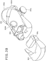
- Figs. 3A and 3B are diagrams showing a configuration example of the externals of the head mount display 10.
- Fig. 3A is a perspective view of the head mount display 10 as seen from a left front direction
- Fig. 3B is an exploded view of the head mount display 10 in which the device is disassembled to some degree.
- the head mount display 10 includes a display unit section 301, an external case 302, a forehead pad section 304, head bands 305, a left headphone section 303L and a right headphone section 303R.
- the display unit section 301 includes many of the main components shown in Fig. 2 including the display system.
- the external case 302 is a case covering the display unit section 301.
- the forehead pad section 304 is a section protruding from the upper surface of the external case 302.
- the head bands 305 are an upper head band 305A and a lower head band 305B.
- the left headphone section 303L and the right headphone section 303R accommodate a left headphone 212L and a right headphone 212R, respectively.
- the display unit section 301 accommodates the left and right display sections and a circuit board.
- the forehead pad section 304 When the user wears the head mount display 10, the forehead pad section 304 is brought into contact with the forehead of the user, whereas the head bands 305 contact with the back of the head.
- the head bands 305 are designed such that their lengths can be adjusted and are made of a stretchable material, so that the head bands 305 are bound around the head to fix the head mount display 10 on the head.
- the head mount display 10 exhibits a light shielding property and is configured to directly cover the eyes of the user.
- the user when the user is wearing the head mount display 10, the user is in the same environment as a dark place, allowing the user to immerse himself or herself into a displayed video picture.
- the user when the user is wearing the head mount display 10, the user can only see the left and right video pictures, which means that the user is put in the same state as being blindfolded.
- the UI operation section 201 has a coordinate input function such as a touch sensor.
- the OSD control section 205 controls an OSD screen superposed on the left and/or right eye video pictures in accordance with the position information inputted through the touch sensor.
- the UI operation section 201 is provided with, as the coordinate input function, a plurality of switches each having a touch sensor. In this case, when the user touches any one of the switches, the OSD control section 205 displays an OSD screen including an image resembling the array of switches over the video picture.
- the UI operation section 201 is provided with a 5-way key serving as switches each having a touch sensor.
- the 5-way key is constituted by upper and lower input keys, left and right input keys, and a confirmation button at the center.
- buttons resembling the 5-way key are displayed as an OSD screen on at least one of the screens of the display panels 211L and 211R. At this time, the button on the OSD screen corresponding to the switch of the 5-way key which the user is touching is highlighted.
- the button can be highlighted in various ways. Examples of the highlighting ways are: enlarging the button relative to the other buttons, displaying it brighter, displaying the button inverted, outlining the button with a bold line, blinking the button, and so on. It suffices as long as the button is displayed in a way that draws attention of the user or allows the user to recognize that the button is being focused. This also applies to the following description.
- the user is touching the right-direction key.
- the button corresponding to the touched right-direction key is displayed in a highlighted state on the OSD screen.
- the user can know which input key of the 5-way key he or she is touching, that is, the user can know which input key of the 5-way key is being selected at that time.
- the button highlighted on the OSD screen changes. Then, after the user has checked from the OSD screen that the user is touching the intended input key, the user presses the confirmation button provided at the center of the 5-way key to confirm input key selection.
- the user is capable of recognizing which portion of the user operation section the user is touching at that time.
- it is possible to correctly carry out a menu selection operation and perform an apparatus operation appropriately.
- the UI operation section 201 is provided with a touch sensor as a coordinate input function. If the touch sensor is disposed, for example, on the front face (on the forehead portion) of the head mount display 10 shown in Fig. 3A , it will be easy for the user to operate the touch sensor with the tip of a finger.
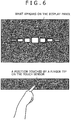
- the OSD control section 205 displays an OSD screen showing a plurality of menu buttons arranged in the horizontal direction superposed on the video picture. At this time, a menu button displayed on the OSD screen corresponding to the horizontal position on the touch sensor where the user is touching is highlighted.
- the user is touching a position at about the center of the touch sensor with the tip of a finger.
- the menu button at the center of the menu buttons arranged in the horizontal direction is displayed in a highlighted state.
- the highlighting effect may be such that a menu button is displayed larger as closer the position of the button is to the position being touched with the user's fingertip.
- the menu button displayed in a highlighted state on the OSD screen changes in response to the position being touched.
- the user is tracing the touch sensor in the horizontal direction toward the right side of the touch sensor with the tip of a finger. Accordingly on the OSD screen, the menu button displayed in a highlighted state is changing toward the right side.
- the user traces the touch sensor in a vertical direction with the tip of a finger in order to confirm the selection of the desired menu button.
- the menu button selected at that time is protruded in the vertical direction as shown in Fig. 8 so as to visually inform the user that the selection of the desired menu button has been accepted.
- the user is capable of recognizing which position on the touch sensor the user is touching, that is, the user is capable of recognizing which menu button is being selected at the present time.
- the user is capable of recognizing which menu button is being selected at the present time.
Landscapes
- Engineering & Computer Science (AREA)
- Theoretical Computer Science (AREA)
- General Engineering & Computer Science (AREA)
- Physics & Mathematics (AREA)
- General Physics & Mathematics (AREA)
- Human Computer Interaction (AREA)
- Computer Hardware Design (AREA)
- Multimedia (AREA)
- Optics & Photonics (AREA)
- Signal Processing (AREA)
- Health & Medical Sciences (AREA)
- Audiology, Speech & Language Pathology (AREA)
- General Health & Medical Sciences (AREA)
- User Interface Of Digital Computer (AREA)
- Controls And Circuits For Display Device (AREA)
Claims (11)
- Kopfmontierte Vorrichtung (10) umfassend:einen oder mehrere Anzeigeabschnitte (301);einen Benutzeroperationsabschnitt (201), der ein Berührungsfeld mit mehreren berührungsempfindlichen Positionen beinhaltet, die dazu ausgelegt sind, eine oder mehrere Koordinaten basierend auf einer ersten Operation zu bestimmen, die von einem Benutzer über den Benutzeroperationsabschnitt durchgeführt wird, während er Inhalte über die kopfmontierte Vorrichtung empfängt; undeinen Steuerung (203) die dazu ausgelegt ist:als Reaktion auf das Detektieren der ersten Operation durch den Benutzer auf mindestens einem des einen oder der mehreren Anzeigeabschnitte einen Bildschirm überlagert, der mehrere Elemente beinhaltet, wobei jedes der mehreren Elemente des überlagerten Bildschirms durch den Benutzer auswählbar ist, um den vom Benutzer empfangenen Inhalt zu steuern; undbasierend auf den ein oder mehreren Koordinaten, die bei der Detektion der ersten Operation bestimmt wurden, mindestens eines der mehreren auswählbaren Elemente des überlagerten Bildschirms im Vergleich zu anderen auswählbaren Elementen des überlagerten Bildschirms hervorheben,wobei der Benutzeroperationsabschnitt dazu ausgelegt ist, die eine oder mehrere Koordinaten basierend auf einer oder mehreren berührungsempfindlichen Positionen der mehreren berührungsempfindlichen Positionen des Berührungsfeldes zu bestimmen, die während der ersten Operation berührt werden;wobei jedes der mehreren auswählbaren Elemente des überlagerten Bildschirms einer anderen berührungsempfindlichen Position des Berührungsfeldes zugeordnet ist; undwobei die Steuerung dazu ausgelegt ist, die Auswahl des hervorgehobenen auswählbaren Elements des überlagerten Bildschirms durch den Benutzer zu bestätigen, basierend auf dem Detektieren einer zweiten Operation, die durch den Benutzer über den Benutzeroperationsabschnitt durchgeführt wird.
- Kopfmontierte Vorrichtung nach Anspruch 1, wobei der Inhalt ein Videoinhalt ist, der auf dem mindestens einen des einen oder der mehreren Anzeigeabschnitte der kopfmontierten Vorrichtung angezeigt wird, und der überlagerte Bildschirm, der die mehreren auswählbaren Elemente beinhaltet, nach dem Detektieren der ersten Operation durch den Benutzer über den Benutzeroperationsabschnitt der kopfmontierten Vorrichtung auf den Videoinhalt überlagert wird.
- Kopfmontierte Vorrichtung nach Anspruch 2, wobei der Videoinhalt einen separaten linken Videoinhalt und einen separaten rechten Videoinhalt beinhaltet, und wobei der eine oder die mehreren Anzeigeabschnitte einen linken Anzeigeabschnitt (211L), der dazu ausgelegt ist, den linken Videoinhalt auf ein linkes Auge des Benutzers zu projizieren, und einen rechten Anzeigeabschnitt (211R), der dazu ausgelegt ist, den rechten Videoinhalt auf ein rechtes Auge des Benutzers zu projizieren, beinhalten.
- Kopfmontierte Vorrichtung nach einem der vorhergehenden Ansprüche, wobei sich der Benutzeroperationsabschnitt an einer freiliegenden Oberfläche der kopfmontierten Vorrichtung befindet.
- Kopfmontierte Vorrichtung nach Anspruch 1, wobei die Steuerung ferner dazu ausgelegt ist, verschiedene der mehreren auswählbaren Elemente des überlagerten Bildschirms entsprechend einer detektierten Bewegung in einer ersten Richtung über eine oder mehrere der mehreren berührungsempfindlichen Positionen des Berührungsfeldes während der ersten Operation unterschiedlich hervorzuheben.
- Kopfmontierte Vorrichtung nach Anspruch 5, wobei die Steuerung ferner dazu ausgelegt ist, die Auswahl des hervorgehobenen auswählbaren Elements des überlagerten Bildschirms durch den Benutzer zu bestätigen, basierend auf einer detektierten Bewegung über das Berührungsfeld in einer zweiten Richtung, die sich von der ersten Richtung unterscheidet.
- Kopfmontierte Vorrichtung nach einem der vorhergehenden Ansprüche, wobei jedes der mehreren auswählbaren Elemente eine andere Menütaste für die Steuerung des vom Benutzer empfangenen Inhalts repräsentiert.
- Kopfmontierte Vorrichtung nach einem der vorhergehenden Ansprüche, wobei die mehreren Elemente des überlagerten Bildschirms jeweils durch den Benutzer auswählbar sind, um Start, Stopp, Lautstärke und Wiedergaberichtung des vom Benutzer empfangenen Inhalts zu steuern.
- Kopfmontierte Vorrichtung nach einem der vorhergehenden Ansprüche, wenn sie von Anspruch 3 abhängig ist, wobei der linke Anzeigeabschnitt und der rechte Anzeigeabschnitt jeweils dazu ausgelegt sind, den linken Videoinhalt und den rechten Videoinhalt entweder gemäß einem 3D-Format, in einem vergrößerten Format oder zur Bildung eines virtuellen Bildes zu projizieren.
- Computerimplementiertes Verfahren, das durch einen Prozessor zur Steuerung der Darstellung von Inhalten in einer kopfmontierten Vorrichtung (10) ausgeführt wird, die einen oder mehrere Anzeigeabschnitte (301) umfasst, wobei das Verfahren umfasst:Bestimmen einer oder mehrerer Koordinaten basierend auf einer ersten Operation, die von einem Benutzer auf einem Benutzeroperationsabschnitt (201) der kopfmontierten Vorrichtung durchgeführt wird, während Inhalte über die kopfmontierte Vorrichtung empfangen werden, wobei der Benutzeroperationsabschnitt ein Berührungsfeld mit mehreren berührungsempfindlichen Positionen beinhaltet;Überlagern, als Reaktion auf das Detektieren der ersten Operation durch den Benutzer auf mindestens einem des einen oder der mehreren Anzeigeabschnitte eines Bildschirms, der mehrere Elemente beinhaltet, wobei jedes der mehreren Elemente des überlagerten Bildschirms durch den Benutzer auswählbar ist, um den vom Benutzer empfangenen Inhalt zu steuern; undHervorheben, basierend auf den ein oder mehreren Koordinaten, die bei der Detektion der ersten Operation bestimmt wurden, mindestens eines der mehreren auswählbaren Elemente des überlagerten Bildschirms im Vergleich zu anderen auswählbaren Elementen des überlagerten Bildschirms,wobei die eine oder mehrere Koordinaten basierend auf einer oder mehreren berührungsempfindlichen Positionen der mehreren berührungsempfindlichen Positionen des Berührungsfeldes bestimmt werden, die während der ersten Operation berührt werden;wobei jedes der mehreren auswählbaren Elemente des überlagerten Bildschirms einer anderen berührungsempfindlichen Position des Berührungsfeldes zugeordnet ist; undwobei die Steuerung dazu ausgelegt ist, die Auswahl des hervorgehobenen auswählbaren Elements des überlagerten Bildschirms durch den Benutzer zu bestätigen, basierend auf dem Detektieren einer zweiten Operation, die durch den Benutzer über den Benutzeroperationsabschnitt durchgeführt wird.
- Nichtflüchtiges, computerlesbares Medium, das computerausführbare Befehle eines Programms zum Ausführen des Verfahrens nach Anspruch 10 speichert.
Applications Claiming Priority (1)
| Application Number | Priority Date | Filing Date | Title |
|---|---|---|---|
| JP2011235171A JP5978592B2 (ja) | 2011-10-26 | 2011-10-26 | ヘッド・マウント・ディスプレイ及び表示制御方法 |
Publications (2)
| Publication Number | Publication Date |
|---|---|
| EP2587300A1 EP2587300A1 (de) | 2013-05-01 |
| EP2587300B1 true EP2587300B1 (de) | 2021-05-19 |
Family
ID=47080326
Family Applications (1)
| Application Number | Title | Priority Date | Filing Date |
|---|---|---|---|
| EP12188864.8A Active EP2587300B1 (de) | 2011-10-26 | 2012-10-17 | Kopfmontierte Anzeige und Anzeigesteuerverfahren |
Country Status (4)
| Country | Link |
|---|---|
| US (2) | US9341847B2 (de) |
| EP (1) | EP2587300B1 (de) |
| JP (1) | JP5978592B2 (de) |
| CN (1) | CN103076678B (de) |
Families Citing this family (27)
| Publication number | Priority date | Publication date | Assignee | Title |
|---|---|---|---|---|
| JP5958689B2 (ja) * | 2012-03-22 | 2016-08-02 | セイコーエプソン株式会社 | 頭部装着型表示装置 |
| KR101509169B1 (ko) * | 2013-05-07 | 2015-04-07 | 배영식 | 헤드 마운트 디스플레이 |
| CN105229720B (zh) * | 2013-05-21 | 2018-05-15 | 索尼公司 | 显示控制装置、显示控制方法以及记录介质 |
| US9563331B2 (en) * | 2013-06-28 | 2017-02-07 | Microsoft Technology Licensing, Llc | Web-like hierarchical menu display configuration for a near-eye display |
| CN103336579A (zh) * | 2013-07-05 | 2013-10-02 | 百度在线网络技术(北京)有限公司 | 穿戴式设备的输入方法和穿戴式设备 |
| US9298298B2 (en) | 2013-12-18 | 2016-03-29 | Microsoft Technology Licensing, Llc | Wearable display input system |
| DE102014006776A1 (de) * | 2014-05-08 | 2015-11-12 | Audi Ag | Bedienvorrichtung für ein elektronisches Gerät |
| CN104144335B (zh) * | 2014-07-09 | 2017-02-01 | 歌尔科技有限公司 | 一种头戴式可视设备和视频系统 |
| JP6340301B2 (ja) * | 2014-10-22 | 2018-06-06 | 株式会社ソニー・インタラクティブエンタテインメント | ヘッドマウントディスプレイ、携帯情報端末、画像処理装置、表示制御プログラム、表示制御方法、及び表示システム |
| CN104503584A (zh) * | 2014-12-31 | 2015-04-08 | 青岛歌尔声学科技有限公司 | 一种触控式头戴显示器 |
| CN104503585A (zh) * | 2014-12-31 | 2015-04-08 | 青岛歌尔声学科技有限公司 | 触控式头戴显示器 |
| CN106155383A (zh) * | 2015-04-03 | 2016-11-23 | 上海乐相科技有限公司 | 一种头戴式智能眼镜屏幕控制方法及装置 |
| US10176638B2 (en) * | 2015-05-18 | 2019-01-08 | Dreamworks Animation L.L.C. | Method and system for calibrating a virtual reality system |
| US20180239417A1 (en) * | 2015-12-30 | 2018-08-23 | Shenzhen Royole Technologies Co. Ltd. | Head-mounted display device, head-mounted display system, and input method |
| EP3399361A4 (de) * | 2015-12-30 | 2019-07-10 | Shenzhen Royole Technologies Co., Ltd. | Kopfmontierte anzeigevorrichtung und steuerungsverfahren dafür |
| CN106970734B (zh) * | 2016-01-13 | 2020-12-18 | 阿里巴巴集团控股有限公司 | 一种显示设备的任务启动方法和装置 |
| CN106502323A (zh) * | 2016-10-20 | 2017-03-15 | 精元电脑股份有限公司 | 能叠加虚拟键盘的显示装置 |
| CN109144378B (zh) * | 2017-06-19 | 2023-07-07 | 中兴通讯股份有限公司 | 数据交互方法、装置、头戴设备和控制设备 |
| US10304207B2 (en) | 2017-07-07 | 2019-05-28 | Samsung Electronics Co., Ltd. | System and method for optical tracking |
| CN107526479B (zh) * | 2017-09-20 | 2020-08-04 | 浙江大华技术股份有限公司 | 一种传感器采集的环境量的显示方法、装置及系统 |
| CN110491322B (zh) * | 2018-05-15 | 2022-11-29 | 瑞昱半导体股份有限公司 | 荧幕显示驱动电路以及控制方法 |
| CN110652190B (zh) * | 2018-06-29 | 2022-12-06 | 浙江绍兴苏泊尔生活电器有限公司 | 烹饪菜单的显示方法和装置、烹饪器具 |
| US11550446B2 (en) | 2020-04-06 | 2023-01-10 | Samsung Electronics Co., Ltd. | Systems and methods for viewing webpages in extended reality environments |
| KR102766471B1 (ko) | 2021-05-19 | 2025-02-12 | 스냅 인코포레이티드 | 증강 현실 디스플레이 디바이스를 위한 터치패드 입력 |
| CN117561497A (zh) * | 2021-05-19 | 2024-02-13 | 斯纳普公司 | 用于增强现实显示设备的触摸板输入 |
| US11561612B1 (en) * | 2021-08-10 | 2023-01-24 | Synaptics Incorporated | AR/VR navigation with authentication using an integrated scrollwheel and fingerprint sensor user input apparatus |
| CN114201104B (zh) * | 2021-12-13 | 2025-01-03 | 杭州灵伴科技有限公司 | 虚拟应用界面更新方法、头戴式显示设备组件和介质 |
Citations (1)
| Publication number | Priority date | Publication date | Assignee | Title |
|---|---|---|---|---|
| EP2363793A2 (de) * | 2010-03-01 | 2011-09-07 | Sony Corporation | Informationsverarbeitungsvorrichtung, Informationsverarbeitungsverfahren und Programm |
Family Cites Families (24)
| Publication number | Priority date | Publication date | Assignee | Title |
|---|---|---|---|---|
| US5579026A (en) * | 1993-05-14 | 1996-11-26 | Olympus Optical Co., Ltd. | Image display apparatus of head mounted type |
| US6046712A (en) * | 1996-07-23 | 2000-04-04 | Telxon Corporation | Head mounted communication system for providing interactive visual communications with a remote system |
| JP2001133724A (ja) | 1999-08-25 | 2001-05-18 | Olympus Optical Co Ltd | 頭部装着型映像表示装置 |
| JP2002189441A (ja) | 2000-10-11 | 2002-07-05 | Olympus Optical Co Ltd | 頭部装着型映像表示装置 |
| JP3714606B2 (ja) | 2001-07-25 | 2005-11-09 | シャープ株式会社 | ヘッドマウントディスプレイ装置 |
| JP2003098471A (ja) | 2001-09-25 | 2003-04-03 | Olympus Optical Co Ltd | 頭部装着型映像表示装置 |
| TWI238348B (en) * | 2002-05-13 | 2005-08-21 | Kyocera Corp | Portable information terminal, display control device, display control method, and recording media |
| JP2004213355A (ja) * | 2002-12-27 | 2004-07-29 | Canon Inc | 情報処理方法 |
| JP2004295159A (ja) * | 2003-02-07 | 2004-10-21 | Sony Corp | アイコン表示システム、アイコン表示方法、電子機器装置およびコンピュータプログラム |
| JP4344568B2 (ja) | 2003-09-05 | 2009-10-14 | 富士フイルム株式会社 | ヘッドマウントディスプレイ及びそのコンテンツ再生方法 |
| JP2007310599A (ja) * | 2006-05-17 | 2007-11-29 | Nikon Corp | 映像表示装置 |
| US8605008B1 (en) * | 2007-05-04 | 2013-12-10 | Apple Inc. | Head-mounted display |
| US8933876B2 (en) * | 2010-12-13 | 2015-01-13 | Apple Inc. | Three dimensional user interface session control |
| JP2009171505A (ja) * | 2008-01-21 | 2009-07-30 | Nikon Corp | ヘッドマウントディスプレイ |
| US9030418B2 (en) * | 2008-06-24 | 2015-05-12 | Lg Electronics Inc. | Mobile terminal capable of sensing proximity touch |
| JP4636164B2 (ja) * | 2008-10-23 | 2011-02-23 | ソニー株式会社 | 頭部装着型ディスプレイ |
| DE112009003521T5 (de) * | 2008-12-04 | 2013-10-10 | Mitsubishi Electric Corp. | Anzeigeeingabevorrichtung |
| HU0900696D0 (en) * | 2009-11-05 | 2009-12-28 | Holakovszky Laszlo | Binocular display device |
| US8665177B2 (en) * | 2010-02-05 | 2014-03-04 | Kopin Corporation | Touch sensor for controlling eyewear |
| US20110214082A1 (en) * | 2010-02-28 | 2011-09-01 | Osterhout Group, Inc. | Projection triggering through an external marker in an augmented reality eyepiece |
| AU2011220382A1 (en) * | 2010-02-28 | 2012-10-18 | Microsoft Corporation | Local advertising content on an interactive head-mounted eyepiece |
| KR101685343B1 (ko) * | 2010-06-01 | 2016-12-12 | 엘지전자 주식회사 | 영상표시장치 및 그 동작방법 |
| JP2011235171A (ja) | 2011-07-29 | 2011-11-24 | Sammy Corp | 遊技機、及びシミュレーションプログラム |
| US8941560B2 (en) * | 2011-09-21 | 2015-01-27 | Google Inc. | Wearable computer with superimposed controls and instructions for external device |
-
2011
- 2011-10-26 JP JP2011235171A patent/JP5978592B2/ja active Active
-
2012
- 2012-10-17 EP EP12188864.8A patent/EP2587300B1/de active Active
- 2012-10-19 US US13/655,824 patent/US9341847B2/en not_active Expired - Fee Related
- 2012-10-19 CN CN201210401222.5A patent/CN103076678B/zh active Active
-
2016
- 2016-03-16 US US15/071,407 patent/US9495029B2/en active Active
Patent Citations (1)
| Publication number | Priority date | Publication date | Assignee | Title |
|---|---|---|---|---|
| EP2363793A2 (de) * | 2010-03-01 | 2011-09-07 | Sony Corporation | Informationsverarbeitungsvorrichtung, Informationsverarbeitungsverfahren und Programm |
Also Published As
| Publication number | Publication date |
|---|---|
| EP2587300A1 (de) | 2013-05-01 |
| US9495029B2 (en) | 2016-11-15 |
| JP5978592B2 (ja) | 2016-08-24 |
| US20130285884A1 (en) | 2013-10-31 |
| JP2013093768A (ja) | 2013-05-16 |
| CN103076678B (zh) | 2017-10-20 |
| US9341847B2 (en) | 2016-05-17 |
| CN103076678A (zh) | 2013-05-01 |
| US20160195952A1 (en) | 2016-07-07 |
Similar Documents
| Publication | Publication Date | Title |
|---|---|---|
| EP2587300B1 (de) | Kopfmontierte Anzeige und Anzeigesteuerverfahren | |
| CN107976809B (zh) | 头戴式视频显示装置 | |
| US9197840B2 (en) | Head mount display and method for controlling head mount display | |
| JP6337418B2 (ja) | 頭部装着型表示装置および頭部装着型表示装置の制御方法 | |
| CN102056002B (zh) | 图像显示装置及其控制方法 | |
| CN104423583B (zh) | 头部佩戴型显示装置、图像显示系统及信息处理装置 | |
| CN103155579B (zh) | 3d图像显示设备及其显示方法 | |
| US20180241983A1 (en) | Display device and control method therefor | |
| JP6492419B2 (ja) | 頭部装着型表示装置、頭部装着型表示装置を制御する方法、コンピュータープログラム、画像表示システム、および、情報処理装置 | |
| JP6379572B2 (ja) | 頭部装着型表示装置および頭部装着型表示装置の制御方法 | |
| JP6331374B2 (ja) | 頭部装着型表示装置 | |
| JP6229381B2 (ja) | 頭部装着型表示装置、頭部装着型表示装置を制御する方法、画像表示システム、情報処理装置 | |
| JP6740613B2 (ja) | 表示装置、表示装置の制御方法、及び、プログラム | |
| KR101888082B1 (ko) | 영상표시장치 및 그 동작방법 | |
| JP2016167844A (ja) | ヘッド・マウント・ディスプレイ及びヘッド・マウント・ディスプレイの制御方法、並びに表示システム及びその制御方法 | |
| US20250085532A1 (en) | Electronic Devices and Corresponding Methods for Rendering Content for a Companion Device | |
| KR101878808B1 (ko) | 영상표시장치 및 그 동작 방법 | |
| KR20130030603A (ko) | 영상표시장치 및 그 동작 방법 | |
| JP2012175494A (ja) | 3次元映像表示装置 | |
| KR20140089208A (ko) | 영상표시장치 및 그 동작 방법 | |
| KR20130029590A (ko) | 영상표시장치 및 그 동작방법 | |
| KR20130059151A (ko) | 이동 단말기 및 그 제어방법 |
Legal Events
| Date | Code | Title | Description |
|---|---|---|---|
| PUAI | Public reference made under article 153(3) epc to a published international application that has entered the european phase |
Free format text: ORIGINAL CODE: 0009012 |
|
| 17P | Request for examination filed |
Effective date: 20121109 |
|
| AK | Designated contracting states |
Kind code of ref document: A1 Designated state(s): AL AT BE BG CH CY CZ DE DK EE ES FI FR GB GR HR HU IE IS IT LI LT LU LV MC MK MT NL NO PL PT RO RS SE SI SK SM TR |
|
| AX | Request for extension of the european patent |
Extension state: BA ME |
|
| 17Q | First examination report despatched |
Effective date: 20160411 |
|
| STAA | Information on the status of an ep patent application or granted ep patent |
Free format text: STATUS: EXAMINATION IS IN PROGRESS |
|
| RIC1 | Information provided on ipc code assigned before grant |
Ipc: H04N 13/344 20180101ALI20201016BHEP Ipc: G06F 1/16 20060101ALI20201016BHEP Ipc: G06F 3/0489 20130101ALI20201016BHEP Ipc: G06F 3/0488 20130101ALI20201016BHEP Ipc: G02B 27/01 20060101AFI20201016BHEP Ipc: G06F 3/01 20060101ALI20201016BHEP Ipc: G06F 3/0481 20130101ALI20201016BHEP |
|
| GRAP | Despatch of communication of intention to grant a patent |
Free format text: ORIGINAL CODE: EPIDOSNIGR1 |
|
| STAA | Information on the status of an ep patent application or granted ep patent |
Free format text: STATUS: GRANT OF PATENT IS INTENDED |
|
| INTG | Intention to grant announced |
Effective date: 20201211 |
|
| GRAS | Grant fee paid |
Free format text: ORIGINAL CODE: EPIDOSNIGR3 |
|
| GRAA | (expected) grant |
Free format text: ORIGINAL CODE: 0009210 |
|
| STAA | Information on the status of an ep patent application or granted ep patent |
Free format text: STATUS: THE PATENT HAS BEEN GRANTED |
|
| AK | Designated contracting states |
Kind code of ref document: B1 Designated state(s): AL AT BE BG CH CY CZ DE DK EE ES FI FR GB GR HR HU IE IS IT LI LT LU LV MC MK MT NL NO PL PT RO RS SE SI SK SM TR |
|
| REG | Reference to a national code |
Ref country code: GB Ref legal event code: FG4D |
|
| REG | Reference to a national code |
Ref country code: CH Ref legal event code: EP |
|
| REG | Reference to a national code |
Ref country code: DE Ref legal event code: R096 Ref document number: 602012075594 Country of ref document: DE |
|
| REG | Reference to a national code |
Ref country code: AT Ref legal event code: REF Ref document number: 1394562 Country of ref document: AT Kind code of ref document: T Effective date: 20210615 |
|
| REG | Reference to a national code |
Ref country code: IE Ref legal event code: FG4D |
|
| RAP4 | Party data changed (patent owner data changed or rights of a patent transferred) |
Owner name: SONY GROUP CORPORATION |
|
| REG | Reference to a national code |
Ref country code: LT Ref legal event code: MG9D |
|
| REG | Reference to a national code |
Ref country code: AT Ref legal event code: MK05 Ref document number: 1394562 Country of ref document: AT Kind code of ref document: T Effective date: 20210519 |
|
| REG | Reference to a national code |
Ref country code: NL Ref legal event code: MP Effective date: 20210519 |
|
| PG25 | Lapsed in a contracting state [announced via postgrant information from national office to epo] |
Ref country code: FI Free format text: LAPSE BECAUSE OF FAILURE TO SUBMIT A TRANSLATION OF THE DESCRIPTION OR TO PAY THE FEE WITHIN THE PRESCRIBED TIME-LIMIT Effective date: 20210519 Ref country code: LT Free format text: LAPSE BECAUSE OF FAILURE TO SUBMIT A TRANSLATION OF THE DESCRIPTION OR TO PAY THE FEE WITHIN THE PRESCRIBED TIME-LIMIT Effective date: 20210519 Ref country code: BG Free format text: LAPSE BECAUSE OF FAILURE TO SUBMIT A TRANSLATION OF THE DESCRIPTION OR TO PAY THE FEE WITHIN THE PRESCRIBED TIME-LIMIT Effective date: 20210819 Ref country code: AT Free format text: LAPSE BECAUSE OF FAILURE TO SUBMIT A TRANSLATION OF THE DESCRIPTION OR TO PAY THE FEE WITHIN THE PRESCRIBED TIME-LIMIT Effective date: 20210519 Ref country code: HR Free format text: LAPSE BECAUSE OF FAILURE TO SUBMIT A TRANSLATION OF THE DESCRIPTION OR TO PAY THE FEE WITHIN THE PRESCRIBED TIME-LIMIT Effective date: 20210519 |
|
| PG25 | Lapsed in a contracting state [announced via postgrant information from national office to epo] |
Ref country code: IS Free format text: LAPSE BECAUSE OF FAILURE TO SUBMIT A TRANSLATION OF THE DESCRIPTION OR TO PAY THE FEE WITHIN THE PRESCRIBED TIME-LIMIT Effective date: 20210919 Ref country code: LV Free format text: LAPSE BECAUSE OF FAILURE TO SUBMIT A TRANSLATION OF THE DESCRIPTION OR TO PAY THE FEE WITHIN THE PRESCRIBED TIME-LIMIT Effective date: 20210519 Ref country code: GR Free format text: LAPSE BECAUSE OF FAILURE TO SUBMIT A TRANSLATION OF THE DESCRIPTION OR TO PAY THE FEE WITHIN THE PRESCRIBED TIME-LIMIT Effective date: 20210820 Ref country code: SE Free format text: LAPSE BECAUSE OF FAILURE TO SUBMIT A TRANSLATION OF THE DESCRIPTION OR TO PAY THE FEE WITHIN THE PRESCRIBED TIME-LIMIT Effective date: 20210519 Ref country code: RS Free format text: LAPSE BECAUSE OF FAILURE TO SUBMIT A TRANSLATION OF THE DESCRIPTION OR TO PAY THE FEE WITHIN THE PRESCRIBED TIME-LIMIT Effective date: 20210519 Ref country code: ES Free format text: LAPSE BECAUSE OF FAILURE TO SUBMIT A TRANSLATION OF THE DESCRIPTION OR TO PAY THE FEE WITHIN THE PRESCRIBED TIME-LIMIT Effective date: 20210519 Ref country code: NO Free format text: LAPSE BECAUSE OF FAILURE TO SUBMIT A TRANSLATION OF THE DESCRIPTION OR TO PAY THE FEE WITHIN THE PRESCRIBED TIME-LIMIT Effective date: 20210819 Ref country code: PT Free format text: LAPSE BECAUSE OF FAILURE TO SUBMIT A TRANSLATION OF THE DESCRIPTION OR TO PAY THE FEE WITHIN THE PRESCRIBED TIME-LIMIT Effective date: 20210920 Ref country code: PL Free format text: LAPSE BECAUSE OF FAILURE TO SUBMIT A TRANSLATION OF THE DESCRIPTION OR TO PAY THE FEE WITHIN THE PRESCRIBED TIME-LIMIT Effective date: 20210519 |
|
| PG25 | Lapsed in a contracting state [announced via postgrant information from national office to epo] |
Ref country code: NL Free format text: LAPSE BECAUSE OF FAILURE TO SUBMIT A TRANSLATION OF THE DESCRIPTION OR TO PAY THE FEE WITHIN THE PRESCRIBED TIME-LIMIT Effective date: 20210519 |
|
| PG25 | Lapsed in a contracting state [announced via postgrant information from national office to epo] |
Ref country code: EE Free format text: LAPSE BECAUSE OF FAILURE TO SUBMIT A TRANSLATION OF THE DESCRIPTION OR TO PAY THE FEE WITHIN THE PRESCRIBED TIME-LIMIT Effective date: 20210519 Ref country code: DK Free format text: LAPSE BECAUSE OF FAILURE TO SUBMIT A TRANSLATION OF THE DESCRIPTION OR TO PAY THE FEE WITHIN THE PRESCRIBED TIME-LIMIT Effective date: 20210519 Ref country code: CZ Free format text: LAPSE BECAUSE OF FAILURE TO SUBMIT A TRANSLATION OF THE DESCRIPTION OR TO PAY THE FEE WITHIN THE PRESCRIBED TIME-LIMIT Effective date: 20210519 Ref country code: SK Free format text: LAPSE BECAUSE OF FAILURE TO SUBMIT A TRANSLATION OF THE DESCRIPTION OR TO PAY THE FEE WITHIN THE PRESCRIBED TIME-LIMIT Effective date: 20210519 Ref country code: SM Free format text: LAPSE BECAUSE OF FAILURE TO SUBMIT A TRANSLATION OF THE DESCRIPTION OR TO PAY THE FEE WITHIN THE PRESCRIBED TIME-LIMIT Effective date: 20210519 Ref country code: RO Free format text: LAPSE BECAUSE OF FAILURE TO SUBMIT A TRANSLATION OF THE DESCRIPTION OR TO PAY THE FEE WITHIN THE PRESCRIBED TIME-LIMIT Effective date: 20210519 |
|
| REG | Reference to a national code |
Ref country code: DE Ref legal event code: R097 Ref document number: 602012075594 Country of ref document: DE |
|
| PLBE | No opposition filed within time limit |
Free format text: ORIGINAL CODE: 0009261 |
|
| STAA | Information on the status of an ep patent application or granted ep patent |
Free format text: STATUS: NO OPPOSITION FILED WITHIN TIME LIMIT |
|
| 26N | No opposition filed |
Effective date: 20220222 |
|
| REG | Reference to a national code |
Ref country code: CH Ref legal event code: PL |
|
| PG25 | Lapsed in a contracting state [announced via postgrant information from national office to epo] |
Ref country code: IS Free format text: LAPSE BECAUSE OF FAILURE TO SUBMIT A TRANSLATION OF THE DESCRIPTION OR TO PAY THE FEE WITHIN THE PRESCRIBED TIME-LIMIT Effective date: 20210919 Ref country code: AL Free format text: LAPSE BECAUSE OF FAILURE TO SUBMIT A TRANSLATION OF THE DESCRIPTION OR TO PAY THE FEE WITHIN THE PRESCRIBED TIME-LIMIT Effective date: 20210519 |
|
| REG | Reference to a national code |
Ref country code: BE Ref legal event code: MM Effective date: 20211031 |
|
| GBPC | Gb: european patent ceased through non-payment of renewal fee |
Effective date: 20211017 |
|
| PG25 | Lapsed in a contracting state [announced via postgrant information from national office to epo] |
Ref country code: MC Free format text: LAPSE BECAUSE OF FAILURE TO SUBMIT A TRANSLATION OF THE DESCRIPTION OR TO PAY THE FEE WITHIN THE PRESCRIBED TIME-LIMIT Effective date: 20210519 |
|
| PG25 | Lapsed in a contracting state [announced via postgrant information from national office to epo] |
Ref country code: LU Free format text: LAPSE BECAUSE OF NON-PAYMENT OF DUE FEES Effective date: 20211017 Ref country code: IT Free format text: LAPSE BECAUSE OF FAILURE TO SUBMIT A TRANSLATION OF THE DESCRIPTION OR TO PAY THE FEE WITHIN THE PRESCRIBED TIME-LIMIT Effective date: 20210519 Ref country code: GB Free format text: LAPSE BECAUSE OF NON-PAYMENT OF DUE FEES Effective date: 20211017 Ref country code: BE Free format text: LAPSE BECAUSE OF NON-PAYMENT OF DUE FEES Effective date: 20211031 |
|
| PG25 | Lapsed in a contracting state [announced via postgrant information from national office to epo] |
Ref country code: LI Free format text: LAPSE BECAUSE OF NON-PAYMENT OF DUE FEES Effective date: 20211031 Ref country code: CH Free format text: LAPSE BECAUSE OF NON-PAYMENT OF DUE FEES Effective date: 20211031 |
|
| PG25 | Lapsed in a contracting state [announced via postgrant information from national office to epo] |
Ref country code: IE Free format text: LAPSE BECAUSE OF NON-PAYMENT OF DUE FEES Effective date: 20211017 |
|
| PG25 | Lapsed in a contracting state [announced via postgrant information from national office to epo] |
Ref country code: HU Free format text: LAPSE BECAUSE OF FAILURE TO SUBMIT A TRANSLATION OF THE DESCRIPTION OR TO PAY THE FEE WITHIN THE PRESCRIBED TIME-LIMIT; INVALID AB INITIO Effective date: 20121017 Ref country code: CY Free format text: LAPSE BECAUSE OF FAILURE TO SUBMIT A TRANSLATION OF THE DESCRIPTION OR TO PAY THE FEE WITHIN THE PRESCRIBED TIME-LIMIT Effective date: 20210519 |
|
| P01 | Opt-out of the competence of the unified patent court (upc) registered |
Effective date: 20230527 |
|
| PG25 | Lapsed in a contracting state [announced via postgrant information from national office to epo] |
Ref country code: MK Free format text: LAPSE BECAUSE OF FAILURE TO SUBMIT A TRANSLATION OF THE DESCRIPTION OR TO PAY THE FEE WITHIN THE PRESCRIBED TIME-LIMIT Effective date: 20210519 |
|
| PG25 | Lapsed in a contracting state [announced via postgrant information from national office to epo] |
Ref country code: MT Free format text: LAPSE BECAUSE OF FAILURE TO SUBMIT A TRANSLATION OF THE DESCRIPTION OR TO PAY THE FEE WITHIN THE PRESCRIBED TIME-LIMIT Effective date: 20210519 |
|
| PGFP | Annual fee paid to national office [announced via postgrant information from national office to epo] |
Ref country code: FR Payment date: 20240919 Year of fee payment: 13 |
|
| PGFP | Annual fee paid to national office [announced via postgrant information from national office to epo] |
Ref country code: DE Payment date: 20240919 Year of fee payment: 13 |
|
| PG25 | Lapsed in a contracting state [announced via postgrant information from national office to epo] |
Ref country code: TR Free format text: LAPSE BECAUSE OF FAILURE TO SUBMIT A TRANSLATION OF THE DESCRIPTION OR TO PAY THE FEE WITHIN THE PRESCRIBED TIME-LIMIT Effective date: 20210519 |