EP2586014B1 - Verfahren zur authentifizierung und/oder identifizierung eines sicherheitsartikels - Google Patents
Verfahren zur authentifizierung und/oder identifizierung eines sicherheitsartikels Download PDFInfo
- Publication number
- EP2586014B1 EP2586014B1 EP11738306.7A EP11738306A EP2586014B1 EP 2586014 B1 EP2586014 B1 EP 2586014B1 EP 11738306 A EP11738306 A EP 11738306A EP 2586014 B1 EP2586014 B1 EP 2586014B1
- Authority
- EP
- European Patent Office
- Prior art keywords
- image
- images
- article
- electronic imager
- relative movement
- Prior art date
- Legal status (The legal status is an assumption and is not a legal conclusion. Google has not performed a legal analysis and makes no representation as to the accuracy of the status listed.)
- Active
Links
Images


Classifications
-
- B—PERFORMING OPERATIONS; TRANSPORTING
- B42—BOOKBINDING; ALBUMS; FILES; SPECIAL PRINTED MATTER
- B42D—BOOKS; BOOK COVERS; LOOSE LEAVES; PRINTED MATTER CHARACTERISED BY IDENTIFICATION OR SECURITY FEATURES; PRINTED MATTER OF SPECIAL FORMAT OR STYLE NOT OTHERWISE PROVIDED FOR; DEVICES FOR USE THEREWITH AND NOT OTHERWISE PROVIDED FOR; MOVABLE-STRIP WRITING OR READING APPARATUS
- B42D25/00—Information-bearing cards or sheet-like structures characterised by identification or security features; Manufacture thereof
- B42D25/30—Identification or security features, e.g. for preventing forgery
- B42D25/36—Identification or security features, e.g. for preventing forgery comprising special materials
- B42D25/378—Special inks
- B42D25/391—Special inks absorbing or reflecting polarised light
-
- G—PHYSICS
- G06—COMPUTING OR CALCULATING; COUNTING
- G06V—IMAGE OR VIDEO RECOGNITION OR UNDERSTANDING
- G06V30/00—Character recognition; Recognising digital ink; Document-oriented image-based pattern recognition
- G06V30/40—Document-oriented image-based pattern recognition
-
- B—PERFORMING OPERATIONS; TRANSPORTING
- B41—PRINTING; LINING MACHINES; TYPEWRITERS; STAMPS
- B41M—PRINTING, DUPLICATING, MARKING, OR COPYING PROCESSES; COLOUR PRINTING
- B41M3/00—Printing processes to produce particular kinds of printed work, e.g. patterns
- B41M3/14—Security printing
- B41M3/148—Transitory images, i.e. images only visible from certain viewing angles
-
- B—PERFORMING OPERATIONS; TRANSPORTING
- B42—BOOKBINDING; ALBUMS; FILES; SPECIAL PRINTED MATTER
- B42D—BOOKS; BOOK COVERS; LOOSE LEAVES; PRINTED MATTER CHARACTERISED BY IDENTIFICATION OR SECURITY FEATURES; PRINTED MATTER OF SPECIAL FORMAT OR STYLE NOT OTHERWISE PROVIDED FOR; DEVICES FOR USE THEREWITH AND NOT OTHERWISE PROVIDED FOR; MOVABLE-STRIP WRITING OR READING APPARATUS
- B42D25/00—Information-bearing cards or sheet-like structures characterised by identification or security features; Manufacture thereof
- B42D25/20—Information-bearing cards or sheet-like structures characterised by identification or security features; Manufacture thereof characterised by a particular use or purpose
- B42D25/29—Securities; Bank notes
-
- B—PERFORMING OPERATIONS; TRANSPORTING
- B42—BOOKBINDING; ALBUMS; FILES; SPECIAL PRINTED MATTER
- B42D—BOOKS; BOOK COVERS; LOOSE LEAVES; PRINTED MATTER CHARACTERISED BY IDENTIFICATION OR SECURITY FEATURES; PRINTED MATTER OF SPECIAL FORMAT OR STYLE NOT OTHERWISE PROVIDED FOR; DEVICES FOR USE THEREWITH AND NOT OTHERWISE PROVIDED FOR; MOVABLE-STRIP WRITING OR READING APPARATUS
- B42D25/00—Information-bearing cards or sheet-like structures characterised by identification or security features; Manufacture thereof
- B42D25/30—Identification or security features, e.g. for preventing forgery
- B42D25/305—Associated digital information
-
- B—PERFORMING OPERATIONS; TRANSPORTING
- B42—BOOKBINDING; ALBUMS; FILES; SPECIAL PRINTED MATTER
- B42D—BOOKS; BOOK COVERS; LOOSE LEAVES; PRINTED MATTER CHARACTERISED BY IDENTIFICATION OR SECURITY FEATURES; PRINTED MATTER OF SPECIAL FORMAT OR STYLE NOT OTHERWISE PROVIDED FOR; DEVICES FOR USE THEREWITH AND NOT OTHERWISE PROVIDED FOR; MOVABLE-STRIP WRITING OR READING APPARATUS
- B42D25/00—Information-bearing cards or sheet-like structures characterised by identification or security features; Manufacture thereof
- B42D25/30—Identification or security features, e.g. for preventing forgery
- B42D25/333—Watermarks
-
- B—PERFORMING OPERATIONS; TRANSPORTING
- B42—BOOKBINDING; ALBUMS; FILES; SPECIAL PRINTED MATTER
- B42D—BOOKS; BOOK COVERS; LOOSE LEAVES; PRINTED MATTER CHARACTERISED BY IDENTIFICATION OR SECURITY FEATURES; PRINTED MATTER OF SPECIAL FORMAT OR STYLE NOT OTHERWISE PROVIDED FOR; DEVICES FOR USE THEREWITH AND NOT OTHERWISE PROVIDED FOR; MOVABLE-STRIP WRITING OR READING APPARATUS
- B42D25/00—Information-bearing cards or sheet-like structures characterised by identification or security features; Manufacture thereof
- B42D25/30—Identification or security features, e.g. for preventing forgery
- B42D25/351—Translucent or partly translucent parts, e.g. windows
-
- B—PERFORMING OPERATIONS; TRANSPORTING
- B42—BOOKBINDING; ALBUMS; FILES; SPECIAL PRINTED MATTER
- B42D—BOOKS; BOOK COVERS; LOOSE LEAVES; PRINTED MATTER CHARACTERISED BY IDENTIFICATION OR SECURITY FEATURES; PRINTED MATTER OF SPECIAL FORMAT OR STYLE NOT OTHERWISE PROVIDED FOR; DEVICES FOR USE THEREWITH AND NOT OTHERWISE PROVIDED FOR; MOVABLE-STRIP WRITING OR READING APPARATUS
- B42D25/00—Information-bearing cards or sheet-like structures characterised by identification or security features; Manufacture thereof
- B42D25/30—Identification or security features, e.g. for preventing forgery
- B42D25/355—Security threads
-
- B—PERFORMING OPERATIONS; TRANSPORTING
- B42—BOOKBINDING; ALBUMS; FILES; SPECIAL PRINTED MATTER
- B42D—BOOKS; BOOK COVERS; LOOSE LEAVES; PRINTED MATTER CHARACTERISED BY IDENTIFICATION OR SECURITY FEATURES; PRINTED MATTER OF SPECIAL FORMAT OR STYLE NOT OTHERWISE PROVIDED FOR; DEVICES FOR USE THEREWITH AND NOT OTHERWISE PROVIDED FOR; MOVABLE-STRIP WRITING OR READING APPARATUS
- B42D25/00—Information-bearing cards or sheet-like structures characterised by identification or security features; Manufacture thereof
- B42D25/30—Identification or security features, e.g. for preventing forgery
- B42D25/36—Identification or security features, e.g. for preventing forgery comprising special materials
- B42D25/364—Liquid crystals
-
- B—PERFORMING OPERATIONS; TRANSPORTING
- B42—BOOKBINDING; ALBUMS; FILES; SPECIAL PRINTED MATTER
- B42D—BOOKS; BOOK COVERS; LOOSE LEAVES; PRINTED MATTER CHARACTERISED BY IDENTIFICATION OR SECURITY FEATURES; PRINTED MATTER OF SPECIAL FORMAT OR STYLE NOT OTHERWISE PROVIDED FOR; DEVICES FOR USE THEREWITH AND NOT OTHERWISE PROVIDED FOR; MOVABLE-STRIP WRITING OR READING APPARATUS
- B42D25/00—Information-bearing cards or sheet-like structures characterised by identification or security features; Manufacture thereof
- B42D25/40—Manufacture
- B42D25/405—Marking
- B42D25/41—Marking using electromagnetic radiation
-
- B—PERFORMING OPERATIONS; TRANSPORTING
- B42—BOOKBINDING; ALBUMS; FILES; SPECIAL PRINTED MATTER
- B42D—BOOKS; BOOK COVERS; LOOSE LEAVES; PRINTED MATTER CHARACTERISED BY IDENTIFICATION OR SECURITY FEATURES; PRINTED MATTER OF SPECIAL FORMAT OR STYLE NOT OTHERWISE PROVIDED FOR; DEVICES FOR USE THEREWITH AND NOT OTHERWISE PROVIDED FOR; MOVABLE-STRIP WRITING OR READING APPARATUS
- B42D25/00—Information-bearing cards or sheet-like structures characterised by identification or security features; Manufacture thereof
- B42D25/40—Manufacture
- B42D25/405—Marking
- B42D25/43—Marking by removal of material
-
- G—PHYSICS
- G07—CHECKING-DEVICES
- G07D—HANDLING OF COINS OR VALUABLE PAPERS, e.g. TESTING, SORTING BY DENOMINATIONS, COUNTING, DISPENSING, CHANGING OR DEPOSITING
- G07D7/00—Testing specially adapted to determine the identity or genuineness of valuable papers or for segregating those which are unacceptable, e.g. banknotes that are alien to a currency
- G07D7/003—Testing specially adapted to determine the identity or genuineness of valuable papers or for segregating those which are unacceptable, e.g. banknotes that are alien to a currency using security elements
-
- G—PHYSICS
- G07—CHECKING-DEVICES
- G07D—HANDLING OF COINS OR VALUABLE PAPERS, e.g. TESTING, SORTING BY DENOMINATIONS, COUNTING, DISPENSING, CHANGING OR DEPOSITING
- G07D7/00—Testing specially adapted to determine the identity or genuineness of valuable papers or for segregating those which are unacceptable, e.g. banknotes that are alien to a currency
- G07D7/01—Testing electronic circuits therein
-
- G—PHYSICS
- G07—CHECKING-DEVICES
- G07D—HANDLING OF COINS OR VALUABLE PAPERS, e.g. TESTING, SORTING BY DENOMINATIONS, COUNTING, DISPENSING, CHANGING OR DEPOSITING
- G07D7/00—Testing specially adapted to determine the identity or genuineness of valuable papers or for segregating those which are unacceptable, e.g. banknotes that are alien to a currency
- G07D7/06—Testing specially adapted to determine the identity or genuineness of valuable papers or for segregating those which are unacceptable, e.g. banknotes that are alien to a currency using wave or particle radiation
- G07D7/12—Visible light, infrared or ultraviolet radiation
- G07D7/128—Viewing devices
-
- G—PHYSICS
- G07—CHECKING-DEVICES
- G07D—HANDLING OF COINS OR VALUABLE PAPERS, e.g. TESTING, SORTING BY DENOMINATIONS, COUNTING, DISPENSING, CHANGING OR DEPOSITING
- G07D7/00—Testing specially adapted to determine the identity or genuineness of valuable papers or for segregating those which are unacceptable, e.g. banknotes that are alien to a currency
- G07D7/20—Testing patterns thereon
- G07D7/202—Testing patterns thereon using pattern matching
- G07D7/207—Matching patterns that are created by the interaction of two or more layers, e.g. moiré patterns
-
- B—PERFORMING OPERATIONS; TRANSPORTING
- B42—BOOKBINDING; ALBUMS; FILES; SPECIAL PRINTED MATTER
- B42D—BOOKS; BOOK COVERS; LOOSE LEAVES; PRINTED MATTER CHARACTERISED BY IDENTIFICATION OR SECURITY FEATURES; PRINTED MATTER OF SPECIAL FORMAT OR STYLE NOT OTHERWISE PROVIDED FOR; DEVICES FOR USE THEREWITH AND NOT OTHERWISE PROVIDED FOR; MOVABLE-STRIP WRITING OR READING APPARATUS
- B42D25/00—Information-bearing cards or sheet-like structures characterised by identification or security features; Manufacture thereof
- B42D25/30—Identification or security features, e.g. for preventing forgery
- B42D25/346—Perforations
-
- B—PERFORMING OPERATIONS; TRANSPORTING
- B42—BOOKBINDING; ALBUMS; FILES; SPECIAL PRINTED MATTER
- B42D—BOOKS; BOOK COVERS; LOOSE LEAVES; PRINTED MATTER CHARACTERISED BY IDENTIFICATION OR SECURITY FEATURES; PRINTED MATTER OF SPECIAL FORMAT OR STYLE NOT OTHERWISE PROVIDED FOR; DEVICES FOR USE THEREWITH AND NOT OTHERWISE PROVIDED FOR; MOVABLE-STRIP WRITING OR READING APPARATUS
- B42D25/00—Information-bearing cards or sheet-like structures characterised by identification or security features; Manufacture thereof
- B42D25/30—Identification or security features, e.g. for preventing forgery
- B42D25/36—Identification or security features, e.g. for preventing forgery comprising special materials
- B42D25/378—Special inks
- B42D25/382—Special inks absorbing or reflecting infrared light
-
- B—PERFORMING OPERATIONS; TRANSPORTING
- B42—BOOKBINDING; ALBUMS; FILES; SPECIAL PRINTED MATTER
- B42D—BOOKS; BOOK COVERS; LOOSE LEAVES; PRINTED MATTER CHARACTERISED BY IDENTIFICATION OR SECURITY FEATURES; PRINTED MATTER OF SPECIAL FORMAT OR STYLE NOT OTHERWISE PROVIDED FOR; DEVICES FOR USE THEREWITH AND NOT OTHERWISE PROVIDED FOR; MOVABLE-STRIP WRITING OR READING APPARATUS
- B42D25/00—Information-bearing cards or sheet-like structures characterised by identification or security features; Manufacture thereof
- B42D25/30—Identification or security features, e.g. for preventing forgery
- B42D25/36—Identification or security features, e.g. for preventing forgery comprising special materials
- B42D25/378—Special inks
- B42D25/387—Special inks absorbing or reflecting ultraviolet light
Definitions
- the present invention relates to the field of security articles, and in particular security documents.
- the phenakistiscope which uses a cardboard disk, pierced with slots, on which a movement is broken down into a series of fixed images, and a handle allowing it to be held during its rotation.
- the zoetrope is also known, which consists of a drum pierced with slots on its upper half and housing inside, in its lower part, a strip of drawings breaking down a movement. When the drum is rotated and the interior is stared at through the slots, the drawings come to life.
- the praxinoscope is also known, the operation of which is based on the principle of the zoetrope, which has several mirrors around its central axis in order to visualize the illusion of movement.
- the request WO 2006/029744 describes in particular the superposition, by folding a document, of two optical elements making it possible to obtain different optical effects depending on the distance separating said optical elements.
- the application WO 02/17242 describes the superposition, by folding an article, of a hologram and hidden information in order to reveal said hidden information.
- the application US 2006-0290136 describes the superposition, by folding a document, of a coded image and an optical lens to decode said image.
- a security element comprising authentication features having a first appearance in transmitted light and a second appearance, different from the first, when the security element is placed on a particular background, for example a liquid crystal display (LCD).
- a particular background for example a liquid crystal display (LCD).
- the invention thus proposes, according to one of its aspects, to exploit the principle of decomposition into movement set out above in order to be able to authenticate and/or identify security articles by visualizing decomposed movements, thus causing an illusion of movement.
- the invention it is possible to benefit from a method allowing the authentication and/or identification of a security article thanks to the restitution of authentication and/or identification information during the relative movement of the first and second images.
- a movement or animation effect may be observed, in particular a movement or animation effect of nested images.
- the authentication and/or identification information may include an animation effect obtained from several nested images of the first image and/or the second image.
- the relative movement between the first and second images may be a physical movement between the article and the electronic imager, i.e. correspond to an actual displacement between the article and the electronic imager.
- the relative movement between the first and second images may correspond to the displacement of one image relative to the other, the article and the electronic imager being in particular fixed relative to each other.
- the authentication and/or identification information may advantageously not be accessible, in particular not be visible, for example to the naked eye or with any device, other than during the relative movement of the first and second images.
- the authentication and/or identification of the security article may thus not result only from the observation of the security article during the relative movement of the first and second images.
- the security article may include a window, for example an at least partially transparent or translucent window, including the first image.
- Examples of the implementation of security windows in security articles are for example described in the publications GB 1 552 853 , which discloses the creation of a window in particular by transparency, laser cutting, abrasion or mechanical incision, EP 0 229 645 which describes the wet creation of a window on one or both sides of a two-ply paper, WO 2004/096482 which describes the creation of a window by laser cutting, CA 2,471,379 which describes the creation of a transparent window and association with a security element and WO 2008/006983 which describes the creation of a transparent window on a bijet paper.
- the first image may appear on a reduced opacity area of the security article.
- a reduced opacity area may in particular correspond to a zone of reduced thickness, to a zone made transparent or to a zone comprising at least one layer of a material of reduced opacity.
- the opacity of said reduced opacity area will in particular be sufficiently low to allow observation in transmission of the first image.
- the image is visible in transmission and in reflection.
- the first image may appear on an at least partially transparent or translucent area of the security item.
- the first image preferably appears on an at least partially transparent or translucent area, such as an at least partially transparent window.
- the second image produced by the electronic imager may be displayed on the electronic imager, for example on a screen of the electronic imager.
- the second image may be projected by the electronic imager, for example onto a background or onto the security article.
- the first image of the security article may be superimposed on the second image projected onto the background.
- the second image may be projected at least partially onto the first image of the security article.
- the relative movement of the first image with respect to the second image can, for example, take place in a plane parallel to the plane containing the second image, or vice versa.
- the relative motion is preferably a translation, or even a rotation or a combination of a translation and a rotation.
- the security article may be folded, with a portion of the article being fixed relative to the second image produced by the electronic imager and another portion of the article, in particular a portion comprising the first image, being driven in a rotational and/or translational movement relative to the second image produced by the electronic imager.
- the security article may be bendable and the relative movement may be a movement in which one portion of the article is fixed relative to the electronic imager while the other portion of the article is movable.
- the first image of the security article may be moved relative to the second image produced by the electronic imager, the second image being stationary.
- the electronic imager may display or project the second image, the second image being stationary, and the user superimposes the first image of the security article on the second image and moves the first image relative to the second image.
- the relative movement between the first and second images thus results from a movement of the article relative to the imager.
- the relative motion between the images occurs without relative motion between the article and the electronic imager.
- the second image produced by the electronic imager may be moved by changing the display or projection, relative to the first image of the security article, the latter being stationary.
- the electronic imager may display or project a second moving image, and the user superimposes the first image on the second image without moving the first image relative to the electronic imager.
- the display or projection of the second image is performed in a time-varying manner so as to generate relative motion with the first image and the article and the electronic imager are further animated by relative motion with respect to each other.
- the item and imager may or may not come into contact when images are superimposed.
- An “electronic imager” means an electronic device capable of producing an image by display or projection.
- the electronic imager may, for example, include a screen on which the second image is displayed.
- the electronic imager may comprise a screen of any known type, for example a computer screen, a television screen, a mobile telephone screen, an electronic book or diary screen, a personal digital assistant screen, a watch face screen, this list being non-limiting.
- the electronic imager may be a projector, with or without a screen on which the projection is carried out.
- the projector may be used to project the second image onto a background or onto the security item.
- the electronic imager may for example be a projector of any known type, for example a slide projector, a video projector, an overhead projector, a pico projector or nano projector, for example a miniaturized video projector integrated into a portable device (PDA, mobile phone, laptop, for example), a cinematographic projector, this list being non-limiting.
- a projector of any known type for example a slide projector, a video projector, an overhead projector, a pico projector or nano projector, for example a miniaturized video projector integrated into a portable device (PDA, mobile phone, laptop, for example), a cinematographic projector, this list being non-limiting.
- the electronic imager preferably makes it possible to generate a pixelated image, each pixel of which is individually addressable, preferably with at least 256 gray levels or colors, with a resolution of between 50 and 1000 dpi (“Dot Per Inch”).
- the electronic imager may be a projector projecting visible, infrared (IR) and/or ultraviolet (UV) light.
- IR visible, infrared
- UV ultraviolet
- the first image may for example be produced at least partially using a visible and/or luminescent ink, for example fluorescent and/or phosphorescent.
- a visible and/or luminescent ink for example fluorescent and/or phosphorescent.
- the electronic imager may include a screen of the LCD ("Liquid Crystal Display”), LED ("Light Emitting Diode”), OLED ("Organic Light Emitting Diode”), laser, plasma, electrochromic, FED ("Field Emission Display”), SED ("Surface-conduction Electron-emitter Display”), LCOS ("Liquid Crystal On Silicon”) type or even a cathode ray tube.
- LCD Liquid Crystal Display
- LED Light Emitting Diode
- OLED Organic Light Emitting Diode
- laser plasma
- electrochromic FED
- FED Field Emission Display
- SED Surface-conduction Electron-emitter Display
- LCOS Liquid Crystal On Silicon
- the electronic image preferably comprises a liquid crystal display (LCD).
- LCD liquid crystal display
- the screen can have a resolution between 50 and 600 dpi, better between 100 and 300 dpi, for example equal to 160 dpi.
- the first image and/or the second image may exhibit polarization properties.
- the second image may be produced by the electronic imager using polarized light, including linearly, circularly, or elliptically polarized light.
- the electronic imager may include a screen emitting polarized light or project polarized light.
- the security article may include a polarizing filter.
- the first image may be produced using a polarizing filter.
- the steps set out above will be carried out so as to form an image which is the positive or negative image of the first image.
- at least one polarizing filter for example by printing, a polyether-based aliphatic polyurethane, for example such as that marketed by the company LAMBERTI under the name Esacote ® PU 21/S.
- the composition comprising cholesteric liquid crystals when, during the implementation of the method according to the invention, the composition comprising cholesteric liquid crystals is located between the polarizing substrate and the electronic imager, the cholesteric liquid crystals modify the polarized light of the electronic imager which is not stopped by the substrate and the areas covered with cholesteric liquid crystals appear transparent when the polarizing substrate is oriented so as to be opaque.
- the cholesteric liquid crystals exhibit an optically variable effect when the polarizing substrate is oriented so as to be opaque.
- the optically variable effect of the cholesteric liquid crystals is more generally known as the "colorshift" effect, the color of the cholesteric liquid crystals depending on the viewing angle and they being observed in particular against a dark background, preferably black in color.
- the "colorshift" effect of the cholesteric liquid crystals can constitute an additional security feature for authenticating and/or identifying the security article.
- the first image is defined by a first polarizing material superimposed on a second polarizing material, the first material extending in particular according to patterns corresponding to the first image and the second material extending continuously.
- the first material is preferably a cholesteric liquid crystal print and the second material is preferably a linearly polarizing substrate.
- patterns corresponding to the first image it is meant that said patterns can form the first image in negative or positive.
- the first and second images have polarization properties
- there is only one orientation of one relative to the other allowing one to partially mask the other.
- there is only one orientation of the first image relative to the second image allowing the second image not to be observed through the polarizing zones of the first image, or vice versa.
- the first and second images having polarization properties are made up of polarizing zones and non-polarizing zones. When they are placed in front of a light source emitting polarized light, there is only one orientation according to which the polarizing zones become opaque.
- the article comprises a polarizing filter with respect to the second image projected or displayed by the electronic imager by means of polarized light, which allows the polarizing filter to mask the polarized light of the electronic imager.
- the polarizing filter may appear opaque, in particular black in color, only in this orientation, preferably unique, of the first image with respect to the second image.
- the presence of a unique orientation of the first and second images relative to each other as described above may for example make it possible to authenticate and/or identify the security article according to a first level of security, in particular by the presence or absence of such an orientation allowing one image to mask the other.
- first and second images When the first and second images are arranged in said orientation, relative movement of one with respect to the other may allow the authentication and/or identification information of the security item to be observed.
- the first image may be printed with a compound, in particular liquid crystals, visible only when placed in front of an electronic imager emitting polarized light, in particular a liquid crystal screen.
- the first image is transparent under non-polarized illumination, for example under natural lighting, and is visible only under polarized illumination using the electronic imager, which provides additional security to the security article.
- the electronic imager e.g. the electronic imager display, and/or the security article may include an indicator to inform the user how to position the first and second images relative to each other to achieve said orientation, e.g. a visual cue.
- the security article may comprise an integrated microcircuit, for example an RFID chip or an optical chip (activated for example by the light from the electronic imager), capable of communicating with the electronic imager so that the latter produces, in particular displays and/or projects, information providing information on how to position the first and second images relative to each other to obtain said orientation.
- an integrated microcircuit for example an RFID chip or an optical chip (activated for example by the light from the electronic imager), capable of communicating with the electronic imager so that the latter produces, in particular displays and/or projects, information providing information on how to position the first and second images relative to each other to obtain said orientation.
- the security article may comprise an integrated microcircuit, for example an RFID chip or an optical chip, capable of communicating with the electronic imager so that the latter produces at least one second image, the association of which with the first image may make it possible to implement the method according to the invention.
- the electronic imager may produce at least one second image associated with a first image of the security article by communication between the electronic imager and the integrated microcircuit.
- the electronic imager may further produce at least one second image from a photo and/or video of the security item, including the first image of the security item or an identifier present on the item, for example a logo or a serial number.
- the photo and/or video may be produced with the electronic imager, an image capture device, for example a digital camera, connected to the electronic imager by a wired or wireless connection and/or be transferred to the electronic imager, for example from a data storage device or via a network, such as the Internet.
- the second image may be produced solely from the photo and/or video of the security item, or alternatively, be produced from the photo and/or video of the security item and additional information, for example information present on the security item, on the photo and/or video, entered by the user, or received from a network, for example from a secure server.
- the electronic imager may, for example, include a program for identifying the security item, and in particular the first image, and for producing, in particular to display and/or project a second image obtained from a database providing information on the second image to be used depending on the security article, in particular the first image.
- the electronic imager can produce several second images and/or the security article can comprise several first images, at least one of the second images making it possible to observe the authentication and/or identification information when superimposed on at least one of the first images according to the method of the invention, or vice versa.
- a given electronic imager may be capable of authenticating and/or identifying security items of different types, including different first images.
- the first images may differ in size, color, shape, or even in the spacing between the dots and/or screen lines or the thickness of the dots and/or screen lines, particularly in the case where the first images are revelation screens and/or combined images as defined below.
- the second images may also differ in their size, color, shape, or even in the spacing between the dots and/or screen lines or the thickness of the dots and/or screen lines, in particular in the case where the second images are revelation screens and/or combined images as defined below, or even in the size of the pixels, the spacing between the pixels or the color of the pixels, in particular in the case where the second images are screens formed by the pixels of a screen as described below.
- Electronic imagers can be differentiated, for example, by their brand, model, resolution, type, such as computer screen, television or telephone screen, or projector, for example.
- first images and/or second images may allow the security item to be authenticated and/or identified independently of the differences mentioned above.
- the second image produced by the electronic imager may for example come from a communication network with which the electronic imager communicates, for example a telephone network, the Internet or an internal network, the image being for example downloaded, and/or be provided with the electronic imager, for example on a data carrier, for example a hard disk, a floppy disk, a USB key, a CD and/or a DVD.
- the security article may, if appropriate, comprise such a data carrier.
- the data carrier may for example be an integrated microcircuit, for example an RFID or optical chip, communicating with the electronic imager.
- the security article may include a luminescent area, such as fluorescent and/or phosphorescent, and the electronic imager may project the second image onto the security article under ultraviolet (UV) illumination.
- a luminescent area such as fluorescent and/or phosphorescent
- UV illumination ultraviolet
- the first image may be a luminescent print, for example made on an opaque black background of the security article, onto which the second image is projected under UV lighting. The first image is then visible only under UV lighting.
- the first image can still be printed on a luminescent background of the security item, so that it is visible under both UV and normal lighting.
- the first image may be concealed in a pattern of the security item. It may also be integrated into a pattern of the security item or constitute at least part of a pattern of the security item. For example, the first image constitutes part of the hair of a character depicted on a banknote.
- the first image may include a reveal frame and the second image may include a combined image comprising at least two nested images, the combined image being associated with the reveal frame, or vice versa.
- association it is meant that the revelation frame is advantageously adapted to allow the visualization of the different nested images of the combined image.
- the person skilled in the art will in particular adapt the resolution of the electronic imager and/or the second image, and the first image so as to allow the visualization of the different nested images of the combined image.
- the presence of several first images can make it possible to authenticate and/or identify the security article independently of the electronic imager used and in particular independently of its resolution.
- the at least partial superposition of the first and second images can make it possible to successively observe the nested images of the combined image by a relative movement of the revelation frame with respect to the combined image. It is then possible to authenticate and/or identify the security article thanks to the restitution of the nested images which constitutes at least in part authentication and/or identification information for the article.
- the rendering of nested images can, for example, create the illusion of movement, particularly animation.
- the electronic imager may comprise a screen, for example such as those described above, the pixels of which serve at least partially to form a second image in the form of a revelation frame.
- the first image advantageously comprises a combined image associated with the revelation frame thus formed at least partially by the pixels of the screen.
- the lines and/or dots of the revelation frame may be formed by the pixels of the screen of the electronic imager.
- the screen may comprise pixels forming at least two revelation frames of different resolutions.
- the screen may comprise two revelation frames with different spacings between dots and/or frame lines and/or different thicknesses of dots and/or frame lines.
- the revelation frame may be formed by a succession of multichrome lines formed by pixels of the screen, in particular lines comprising pixels having three red, green and blue cells (of the RGB type), the pixels being spaced from each other so as to form monochrome lines devoid of pixels, in particular of black color.
- the pixels may also have four red, green, blue and yellow cells.
- the pixels of the screen can be used to form an intrinsic revelation frame of the screen without requiring the display of a particular image on the screen.
- the screen is illuminated uniformly in white, by lighting the red, green and blue cells of all the pixels of the image.
- the imager can be used in two ways. In the first case, an image corresponding to a non-uniform lighting of the imager pixels is displayed. In the second case, all the pixels of the imager are lit in a uniform manner and the native frame resulting from the arrangement of the pixel cells within the imager is used.
- observing the nested images by relative motion of the first image as a combined image relative to the second image as a revealing frame can allow observing a monochrome animation of the nested images according to a first motion of the first and second images relative to each other, and a multichrome animation of the nested images according to a second motion of the first and second images relative to each other.
- the second motion takes place in a different direction from the first, preferably perpendicular.
- the combined image, and the nested images it comprises may be raster images, i.e. images whose different gradation levels are obtained by raster points and/or lines.
- the raster images may for example be halftone images, making it possible to render in particular levels of color, for example gray, from groupings of raster points.
- the combined image may correspond to the decomposition of a movement of a pattern, for example of a text, alphanumeric signs, ideograms, an object, a person and/or an animal.
- the nested images may represent successive positions and/or successive movements of a pattern, for example of an object, a person and/or an animal.
- the combined image can advantageously be obtained by superimposing the nested images each representing a position of the pattern.
- Nested images can represent information that is hidden and revealed successively by relative movement, in particular by translation, of the revealing frame on the combined image.
- the combined image retains a recognizable aesthetic, in particular so as to constitute a first element of authentication.
- the revelation frame can allow the human eye to visualize a different nested image at a time, the observer's brain being able to reconstruct, for example, a movement or observe hidden information.
- screened image and “revelation screen”, within the meaning of the present invention, must be given a broad meaning which covers all types of screens or pseudo-screens, comprising a juxtaposition of areas contrasting with each other, for example light areas and dark areas, distinguishable from each other, the shape of these light areas and these dark areas not being limited to a particular shape.
- the combined image and/or the revelation frame may comprise a set of points and/or lines, parallel or not, the size and/or spacing between them of which are variable or constant, this set forming a succession of light and dark zones, for example white and black.
- the observation of the nested images can be done by translation in at least two directions. This is in particular a direction parallel to said lines and a direction parallel to said columns.
- the combined image and/or the revelation frame may in particular comprise a set of lines, preferably parallel to each other, of defined thickness and spacing between them.
- the lines may have the same thickness and/or the same spacing between them.
- the combined image and/or the revelation frame may for example comprise a succession of dark and light lines, for example black and white.
- the thickness of the dark lines of the combined images is for example equal to the thickness of the light lines of the revelation means.
- the thickness of the light lines of the nested images is for example equal to the thickness of the dark lines of the revelation means.
- the revealing frame may include opacifying bands with parallel edges, possibly not straight.
- the presence of opacifying bands with non-straight edges may make reproduction more difficult by a counterfeiter.
- the reveal screen may include portions of bands, substantially identical in color or identical to the bands of the combined image, and arranged so as to mask certain bands of the combined image to achieve the desired effect.
- the area, in particular the length and/or the width and/or the largest dimension, of the revealing screen may be greater than or equal to the area, in particular the length and/or the width and/or the largest dimension, of the image. combined. In this way, it is possible to visualize the entire reconstruction of the movement produced by the relative displacement between the combined image and the revelation frame.
- the revealing frame can have any shape, for example circular, oval, star-shaped, polygonal, for example rectangular, square, hexagonal, pentagonal, diamond-shaped, among others.
- the security article may comprise a first part of a revelation frame or a combined image, the electronic imager comprising the other part.
- the security article and the optical imager may then be positioned so as to bring together the two parts of the revelation frame or the combined image separated for the implementation of the method according to the invention.
- two combined images of different dimensions can be associated.
- the combined image of smaller dimension is in particular repeated, in particular according to a network, in particular of lines and columns, in order to appear as a background on which the combined image of larger dimension is arranged.
- the associated revelation frame then comprises a first revelation frame adapted to the combined image of larger dimension, and a second revelation frame adapted to the combined image of smaller dimension.
- the two different combined images can have similarities and/or complement each other. They can in particular be identical and/or symmetrical.
- the first image may be carried on the security article by a printing process, for example offset, intaglio, laser, gravure, letterpress or screen printing.
- the first image may be printed, for example by colored or non-colored inks, visible to the naked eye, under ultraviolet (UV) and/or infrared (IR) light, opaque or luminescent, in particular fluorescent, thermochromic, photochromic, with an interference effect, in particular iridescent, or with an optically variable effect depending on the angle of observation (goniochromatic), in particular comprising liquid crystals, metallic or non-metallic, magnetic or non-magnetic inks, among others.
- UV ultraviolet
- IR infrared
- the first image may further include metallizations and/or demetallizations, for example in aluminum.
- metallizations and/or demetallizations may be used in order to avoid counterfeiting by printing.
- metallizations and/or demetallizations of different colors are preferably used, for example by means of aluminum and copper.
- the first image may have a watermark or pseudo-watermark.
- Watermarks are produced by techniques well known in the paper industry. Pseudo-watermarks reproduce the appearance of a watermark by presenting differences in opacity, they can be obtained mechanically by applying pressure with or without the addition of heat and/or chemically by applying a composition, for example by locally increasing the transparency of the paper using transparentizing substances. The density of fibrous material of the pseudo-watermark can be uniform unlike a conventional watermark.
- the first and second images can be colored, and in particular different colors.
- the first image may be carried by a patch and/or foil appearing on the security item.
- the patch and/or foil may include metallizations and/or demetallizations, for example in aluminum, or any type of printing.
- the patch and/or foil may feature holographic prints and/or liquid crystals.
- the first image may still be carried by a security thread, incorporated on the surface, in mass or in window(s) in the security article.
- the security thread may have a width sufficient to allow the first image to be displayed therein in its entirety.
- the width of the security thread is, for example, between 3 and 20 mm, and more preferably between 4 and 10 mm.
- the first image advantageously appears on an area of the article that is at least partially transparent.
- the first image may be at least partially transparent.
- the at least partially transparent area may correspond to a recess, crossing or not, of the article where the first image is located.
- the area is, for example, made of translucent tracing paper.
- the area may further comprise or be constituted by a polymer layer comprising for example polyethylene (PE), polyvinyl chloride (PVC), polyethylene terephthalate (PET), polycarbonate (PC), polyester carbonate (PEC), polyethylene terephthalate glycol (PETG), acrylonitrile butadiene styrene (ABS) or a light-collecting film, for example of the "waveguide” type, for example a polycarbonate-based luminescent film marketed by BAYER under the name LISA ® .
- the first image is preferably obtained by laser engraving.
- the area may also be made transparent by applying a generally oily composition that makes the area permanently transparent, such as a composition made of oil and transparent mineral material as described in the patent US 2,021,141 , or as for example a composition in the form of a wax combined with a solvent as described in the patent US 1,479,437 .
- a generally oily composition that makes the area permanently transparent, such as a composition made of oil and transparent mineral material as described in the patent US 2,021,141 , or as for example a composition in the form of a wax combined with a solvent as described in the patent US 1,479,437 .
- the area can also be made transparent by locally applying a hot transfer wax, as described in the patent. US 5,118,526 .
- a fibrous layer comprising a heat-fusible material, for example polyethylene, as described in the patent, may be used for the area.
- EP 0 203 499 which under the local action of heat will see its transparency vary.
- the security article as well as the elements it contains, such as for example the first image, a window, a security thread, a patch and/or a foil with or without the first image, may contain one or more additional security elements as defined below.
- security elements some are detectable by eye, in daylight or artificial light, without the use of a particular device.
- These security elements include, for example, colored fibers or boards, printed or totally or partially metallized threads. These security elements are called first level.
- Additional security elements are detectable only using a relatively simple device, such as a lamp emitting in the ultraviolet (UV) or infrared (IR) range.
- These security elements include, for example, fibres, planchettes, strips, wires or particles.
- These security elements may or may not be visible to the naked eye, being, for example, luminescent under the illumination of a Wood lamp emitting at a wavelength of 365 nm.
- These security elements are called second-level security elements.
- Additional security elements require a more sophisticated detection device for their detection.
- These security elements are, for example, capable of generating a specific signal when they are subjected, simultaneously or not, to one or more external excitation sources. Automatic detection of the signal makes it possible to authenticate the article, if necessary.
- These security elements include, for example, tracers in the form of active materials, particles or fibres, capable of generating a specific signal when these tracers are subjected to optronic, electrical, magnetic or electromagnetic excitation. These security elements are called third-level security elements.
- the security article and the elements it contains may have first, second or third level security features.
- the first image may be associated with metallization, luminescence, for example fluorescence and/or phosphorescence, thermochromic (thermochromic ink for example), magnetic, polarizing (liquid crystal ink for example) effects, this list being non-limiting.
- luminescence for example fluorescence and/or phosphorescence
- thermochromic thermochromic ink for example
- magnetic, polarizing liquid crystal ink for example
- the security item may be a means of payment, such as a bank note, a check or a restaurant voucher, an identity item such as an identity card, a visa, a passport or a driving licence, a lottery ticket, a transport ticket or an entry ticket to cultural or sporting events, or an access card, for example for areas with restricted access.
- a bank note such as a bank note, a check or a restaurant voucher
- an identity item such as an identity card, a visa, a passport or a driving licence
- a lottery ticket such as a transport ticket or an entry ticket to cultural or sporting events
- an access card for example for areas with restricted access.
- the security item may be an access card comprising a first image, for example in the form of a combined image, which the cardholder presents at an access control point, for example of a company, where the method according to the invention is implemented, for example using a second image in the form of a revealing frame, to authorize access.
- the invention also relates, according to another of its aspects, to a security article, in particular a security document, for implementing the method as defined above.
- the photo and/or video may be taken with the electronic imager, an image capture device, such as a digital camera, connected to the electronic imager and/or transferred to the electronic imager, such as from a data storage device or via a network, such as the Internet.
- an image capture device such as a digital camera
- the invention also relates, according to another of its aspects, to a security article comprising a first image superimposable on at least one second image produced by an electronic imager, the first image being in particular defined by a first polarizing material.
- the first polarizing material may be superimposed on a second polarizing material, the first material preferably being a cholesteric liquid crystal pattern and the second material preferably being a linearly polarizing substrate.
- the first image may be defined by a polarizing substrate rendered locally unpolarized so as to form the first image.
- the first image can be defined by a print of a polarizing ink.
- the article may comprise several different first images, each first image being superimposable on at least one second image produced by an electronic imager adapted to this first image, the electronic imagers having in particular different resolutions.
- the invention also relates, according to another of its aspects, to a security article comprising several different first images, each first image being superimposable on at least one second image produced by an electronic imager adapted to this first image, the electronic imagers having in particular different resolutions.
- the security article can be used in the method as described above.
- the features described in relation to the method according to the invention can be applied to the security article.
- ink or varnish can be made to be compatible with a demetallization process.
- the demetallization process can, for example, correspond to a chemical process using soda to remove the area(s) where the metal is not covered by the ink or varnish.
- the demetallization process may also include the application of a varnish or ink, which may be matte or colored, having optical properties different from those of the metallic layer.
- the ink may be chosen from colored or non-colored inks, visible to the naked eye, under UV and/or IR light, opaque or luminescent, in particular fluorescent, thermochromic, photochromic, with an interference effect, in particular iridescent, or with an optically variable effect depending on the angle of observation (goniochromatic), in particular comprising liquid crystals, metallic or non-metallic, magnetic or non-magnetic inks, among others.
- the ink is fluorescent and/or phosphorescent under UV and/or IR light.
- the article may include first-level and/or second-level security features, as described above.
- the article may include security features in the form of prints and/or markers, in particular thermochromic and/or photochromic.
- the manufacturing method according to the invention it is possible to observe on a first face of the article a first shiny metallic image and on the second opposite face of the article a first image having the appearance of ink or varnish, for example colored or matt.
- FIG. 1 It was represented on the figure 1 a block diagram relating to steps implemented in an exemplary method according to the invention.
- a first image of the security article is at least partially superimposed with a second image produced by an electronic imager.
- a relative motion is generated between the first and second images.
- the three steps I, II and III can be carried out simultaneously or not.
- the electronic imager 10 is for example a computer screen on which a second image 30 is displayed.
- the security article 1 is for example in the form of a banknote and comprises a first image 20.
- the security article 1 is placed on the screen of the electronic imager 10 so as to at least partially superimpose the first image 20 on the second image 30, then the security article 1 is moved relative to the screen of the electronic imager 10 to observe authentication and/or identification information of the security article 1, in accordance with the steps described in figure 1 .
- the security article 1 in reference remains stationary relative to the screen of the electronic imager 10 and the second image 30 is animated by a movement on the screen, for example a translation, for example using a program activated or not by the user.
- the electronic imager 10 is for example in the form of a digital projector, projecting a second image 30 onto a background 50, for example the wall of a room.
- the security article 1 comprising the first image 20 can then be superimposed at least partially on the second image 30 projected on the background 50 so as to implement the steps described with reference to the figure 1 .
- the electronic imager 10 is a projector which projects the second image 30 directly onto the security article 1.
- the second image 30 can, as in the example of the figure 4 , be projected, for example in the form of a “W”, onto an area of the security article 1 where the first image 20 is not present. Then, the security article 1 can for example be folded on itself so as to superimpose the first image 20, for example in the form of “A”, on the second image 30 projected by the electronic imager 10, to implement the steps described in figure 1 .
- the part of the security article 1 comprising the first image 20 can in particular be folded over the part comprising the second image 30, this part remaining stationary, so that the second image 30 is located between the imager 10 and the first image 20.
- the second image 30 is projected directly onto the first image 20 of the article 1.
- the projection of the second image 30 onto the first image 20 of the security article 1 can then allow at least partial superposition of the first and second images.
- the electronic imager 10 is for example moved relative to the article so as to implement steps II and III described with reference to the figure 1 .
- the electronic imager 10 is a screen displaying several second images 30a, 30b, 30c and 30d.
- the second images 30a to 30d may have different properties, for example different shapes, colors, dimensions, dots or raster lines.
- the second images 30a to 30d are differentiated so as to allow at least one of them to be associated with at least one first image 20 present on a security article 1.
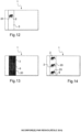
- the security article 1 comprises several different first images 20, as can be seen for example in the figure 14 , and the electronic imager 10 produces one or more second images 30.
- the electronic imager 10 produces one or more second images 30.
- the electronic imager 10 may display one or more indicators 40a, 40b, 40c and 40d for informing the user on how to position the security article 1 relative to the imager.
- the indicators 40a to 40d can make it possible to know where to position the upper right corner of the security article 1, so as to correctly superimpose a first image 20 of a security article 1 on a second image 40a, 40b, 40c or 40d displayed on the screen of the electronic imager 10.
- the security article 1 prefferably includes an additional security element 51 of any known type, for example one of those described previously, for example a luminescent security thread.
- the security article 1 may comprise an integrated microcircuit 52, for example an RFID or optical chip, making it possible to communicate with the electronic imager 10 in order to control the display of an indicator as described previously or to broadcast information on how to position the first and second images.
- an integrated microcircuit 52 for example an RFID or optical chip
- the first image 20 may comprise a revelation frame 3 and the second image 30 may comprise a combined image 2 comprising at least two nested images 2a, the combined image 2 being associated with the revelation frame 3, or vice versa, as mentioned above.
- the nested images 2a correspond for example to four different positions of the elephant and thus make it possible to create a decomposition of the elephant's movement.
- Each nested image 2a may comprise, as illustrated, a set of parallel lines, spaced apart regularly or not, and having variable thicknesses.
- Images 2a are superimposed on each other so as to form a combined pattern which corresponds to combined image 2.
- the revelation frame 3 is for example rectangular in shape and comprises a set of parallel lines, spaced apart regularly or not, and having variable thicknesses.
- the revelation frame 3 has an area, length and width greater than those of the combined image 2, thus making it easier to visualize all of the movements of the elephant during the relative movement between the combined image 2 and the revelation frame 3.
- the combined image 2 and the revelation frame 3 have sets of alternating dark and light lines, including black and white, but this could be different.
- the lines could be colored and could be different for the combined image 2 and for the revelation frame 3.
- the article 1 comprises a window 4, preferably at least partially transparent, in which the first image 20 appears in the form of a revealing frame 3.
- the first image 20 can for example be formed by printing, in particular intaglio, metallization or demetallization.
- the security article 1 comprises a patch 5 on which the first image 20 appears in the form of a revelation frame 3, the patch 5 comprising for example holographic prints.
- Patch 5 may be at least partially transparent.
- the revelation frame 3 may include holographic prints and/or metallizations and/or demetallizations.
- the security article 1 comprises a security thread 6 on which the first image 20 appears in the form of a combined image 2.
- the security thread 6 may also be at least partially transparent or have a partially transparent area at the combined image 2.
- the security article 1 comprises a security thread 6 on which the first image 20 appears in the form of a revelation frame 3.
- the security thread 6 may be at least partially transparent or have an at least partially transparent area.
- the revealing frame 3 may extend from one edge of the security article 1 to the opposite edge.
- the security article 1 comprises a security thread 6 comprising several first images 20 in the form of combined images 2.
- the first images 20 are produced in such a way that the security article 1 can be used with different electronic imagers, in particular having different resolutions, each first image 20 being adapted to a given resolution of an electronic imager.
- the security thread 6 may be at least partially transparent or comprise at least one at least partially transparent area, in particular at the level of a combined image 2.
- first images 20 on the security article 1 arranged on a security thread 6 can make it possible to simplify the manufacturing process of the security article 1 by incorporating the security thread 6 into a substrate, in particular a fibrous one. In particular, incorporation into the mark may not be necessary.
- the at least partially transparent areas may be located at the combined images 2 or the revelation frames 3, or at both at the same time.
- the security thread 6 can be introduced into the security article 1 in a conventional manner, for example on the surface, in mass or in window(s).
- the combined images 2 and/or the revelation frames 3 may further comprise a polarizing filter.
- the security article 1 can then be authenticated and/or identified by means of an electronic imager 10 emitting polarized light.
- a second image 30 (or a first image) comprising two different combined images 21 and 22 is schematically represented.
- the second combined image 22 is for example a symmetrical image of the first combined image 21 after possible modification of its size, in order to obtain a network of combined images 22 organized in rows and columns.
- FIG 16 represents the first image 20 (respectively the second image) corresponding, in the form of a revelation frame 3 of the nested images 21a and 22a schematically represented on the figure 16 .
- This revelation frame 3 comprises the association of two elementary frames 3c and 3d allowing the nested images 21a and 22a to be observed respectively.
- Frame 3c comprises, for example, a succession of black bands alternating with bands of frame 3d consisting of an alternation of white and black lines, with a smaller pitch.
- a first image 20 (or second image) is schematically represented in the form of a combined image 22 arranged according to a network of combined images 22 around a revelation frame 31.
- the second image 30 (respectively the first image) is schematically represented in the form of a combined image 21 surrounded by a revelation frame 32.
- the electronic imager 10 is for example in the form of a mobile telephone on which a second image 30 is displayed in the form of a combined image 2 (visible on the figure 21 ).
- the security article 1 comprises a polarizing filter on which the first image 20 has been formed in the form of a revelation frame 3.
- FIG. 20 illustrates the superposition of the security article 1 comprising the first image 20 in the form of a revelation frame 3 on the second image 30 in the form of a combined image 2 produced by the electronic imager 10, the latter emitting polarized light.
- the user moves the security item 1 to bring it into a crossed orientation allowing the opacity of the polarizing filter to be observed with respect to polarized light.
- the security article 1 comprising the revelation frame 3 is moved by a translational movement according to the arrows F relative to the combined image 2 displayed by the screen of the electronic imager 10, so as to make the animation of the nested images appear.
- the movement takes place while maintaining the relative orientation of the frame relative to the screen.
- Such a method makes it possible to authenticate and/or identify the security article 1 according to several security levels.
- Revealing the animation of the nested images by moving the reveal frame 3 relative to the combined image 2 provides a second level of security.
- the electronic imager 10 is preferably a screen, in particular of the LCD type, comprising a plurality of pixels.
- FIG 22 partially represents the electronic imager 10 in the form of an LCD screen comprising a plurality of pixels, and the figure 23 represents a part of the figure 22 enlarged.
- the screen may comprise a regular arrangement of pixels arranged in the form of horizontal and vertical lines.
- the horizontal lines may comprise a repetition of three pixels P 1 , P 2 , and P 3 , of different colors, for example RGB.
- horizontal lines of pixels may be separated by black N areas without pixels.
- the combined image 2 and the revelation frame 3 are produced in such a way as to allow the observation of an animation by a relative movement in two different directions, in particular perpendicular.
- Such an effect is for example obtained by means of a revelation frame 3 consisting of rows and columns of points, for example square-shaped, and a suitable combined image 2, such as that shown in the figure 25 .
- the electronic imager 10 can correspond to the screen of a mobile phone, having for example a resolution of 160 dpi, thus making it possible to obtain a revelation frame whose pixels are spaced approximately 159 ⁇ m apart.
- the combined image 2 on the security article 1 may be contained in a through-window of the security article 1, sealed by a transparent plastic strip.
- the transparent plastic strip may have circular polarizing filter properties.
- the security article 1 comprising the polarizing transparent plastic strip on which the combined image 2 is formed can be manufactured so that the polarizing properties are preserved on the constituent areas of the combined image, representing for example several successive positions of a spiral.
- the combined image 2 can be produced as described above, for example by printing the plastic strip with a specific ink providing a polarizing property or by heating, for example with a laser, areas which are to be devoid of polarizing properties.
- the electronic imager 10 in the form of a screen comprises a first part 30a of the second image in the form of a revelation frame 3a, as can be seen in the figure 24 .
- the security article 1 comprises the other part 30b of the second image in the form of a revealing frame 3b, for example in an at least partially transparent window of the article.
- the security article 1 comprises the first image 20 in the form of a combined image 2, for example in an at least partially transparent window of the article, as can be seen in the figure 25 .
- the security article 1 When the security article 1 is folded on itself so as to superimpose the combined image 2 on the part 3b of the revelation frame, then superimposed on the electronic imager 10 so as to superimpose the combined image 2 and the part 3b of the revelation frame on the part 3a of the revelation frame formed on the screen of the electronic imager 10, it is possible to implement the method according to the invention by relative movement of the part of the security article 1 comprising the combined image 2 with respect to the part of the security article 1 comprising part 3b of the revelation frame, the latter being stationary relative to the screen comprising part 3a of the revelation frame to allow the reconstruction of the revelation frame and the observation of the nested images, as can be seen in the figure 26 .
- the combined image 2 advantageously allows the observation of an animation or two animations by a relative movement respectively in two different directions, notably perpendicular.
- a security article 1 in the form of a passport comprising a first image 20, printed as a combined image 2, and an RFID chip 60.
- the chip 60 is able to communicate with the electronic imager 10 (not shown) to enable the production of the second image 30 associated with the first image 20.
- the first image 20 is illuminated with the electronic imager.
- the chip 60 comprises information transmitted to the electronic imager which then projects the second image according to this information.
- the security article 1 in the form of a passport, comprises a first image 20 in the form of a combined image 2 obtained by metallization of a transparent plastic film inserted in the passport through a window 4.
- the passport 1, in particular the combined image 2 is photographed and/or filmed by a digital camera 70 belonging to or connected to the electronic imager.
- a recognition program can then make it possible to recognize the combined image 2 and to acquire from a database a second image associated with the first image.
- the database is for example stored on a secure server.
- the second image thus obtained is displayed and/or projected by the electronic imager to make it possible to authenticate and/or identify the passport 1 by relative movement of the first and second images.
- the security article 1 comprises a first printed image 20, representing for example the face of a person, this first image 20 comprising a combined image 2, for example at the level of the person's hair.
- this first image 20 comprising a combined image 2, for example at the level of the person's hair.
- the combined image 2 appears in a transparent, translucent or reduced opacity zone of the security article 1.
- the banknote In authenticate and/or identify the banknote 1, it is for example possible to photograph the banknote, in particular the first image 20, and to produce a second image associated with the first image, this second image being obtained from the photograph of the banknote.
- the electronic imager is a mobile phone capable of photographing the banknote, and a program internal to the mobile phone makes it possible to download a second image associated with the first image which can then be displayed on the screen of the mobile phone to implement the method according to the invention.
- said internal program of the mobile phone makes it possible to generate said second image associated with said first image.
- the security article 1 comprises a substrate 80 on which is printed an opaque black layer 81.
- the opaque black layer 81 for example completely covers the substrate 80.
- the associated electronic imager is capable of projecting a second image 30, not shown, onto the first image 20 under ultraviolet (UV) lighting.
- UV ultraviolet
- the first image 20 is not observable under normal lighting due to the presence of the black opaque layer 81.
- the first image 20 is observable and it is possible to at least partially superimpose the second image 30 on it, in particular in the form of a revelation frame, to implement the method according to the invention.
- the first image 20 is printed with an opaque black ink on a luminescent layer 81, in particular fluorescent and/or phosphorescent, itself printed on the substrate 80.
- the first image 20 is visible under both normal lighting and UV lighting.
Landscapes
- Physics & Mathematics (AREA)
- Engineering & Computer Science (AREA)
- General Physics & Mathematics (AREA)
- General Health & Medical Sciences (AREA)
- Toxicology (AREA)
- Health & Medical Sciences (AREA)
- Manufacturing & Machinery (AREA)
- Computer Vision & Pattern Recognition (AREA)
- Computer Security & Cryptography (AREA)
- Electromagnetism (AREA)
- Business, Economics & Management (AREA)
- Accounting & Taxation (AREA)
- Finance (AREA)
- Theoretical Computer Science (AREA)
- Multimedia (AREA)
- Chemical & Material Sciences (AREA)
- Crystallography & Structural Chemistry (AREA)
- Artificial Intelligence (AREA)
- Image Processing (AREA)
- Editing Of Facsimile Originals (AREA)
- Credit Cards Or The Like (AREA)
- Liquid Crystal (AREA)
- Burglar Alarm Systems (AREA)
Claims (15)
- Verfahren zur Authentifizierung und/oder Identifizierung eines Sicherheitsartikels (1), der ein erstes Bild (20) umfasst, umfassend die Schritte, die aus Folgendem bestehen:- Überlagern, mindestens teilweise, des ersten Bildes (20) des Artikels (1) mit einem zweiten Bild (30), das durch einen elektronischen Bildgeber (10) erzeugt wird, wobei der Sicherheitsartikel (1) insbesondere eine integrierte Mikroschaltung (60) umfasst, die dazu fähig ist, mit dem elektronischen Bildgeber (10) zu kommunizieren, damit dieser das zweite Bild (30) erzeugt, wobei der elektronische Bildgeber (10) insbesondere einen Bildschirm umfasst, dessen Pixel mindestens teilweise dazu dienen, das zweite Bild (30) in Form eines Enthüllungsrasters (3) zu bilden,- Ausführen einer relativen Bewegung zwischen dem ersten und zweiten Bild (20, 30), um das Beobachten einer Information zur Authentifizierung und/oder Identifizierung des Sicherheitsartikels (1) während der relativen Bewegung zwischen dem ersten und zweiten Bild (20, 30) zu ermöglichen, wobei die Authentifizierungs- und/oder Identifizierungsinformation nur während der relativen Bewegung des ersten und zweiten Bildes zugänglich ist,wobei während der relativen Bewegung zwischen dem ersten (20) und zweiten (30) Bild ein Bewegungs- oder Animationseffekt verschachtelter Bilder (2a) beobachtet wird.
- Verfahren nach Anspruch 1, wobei das erste Bild (20) ein Enthüllungsraster (3) umfasst und das zweite Bild (30) ein kombiniertes Bild (2) umfasst, das mindestens zwei verschachtelte Bilder (2a) umfasst, wobei das kombinierte Bild (2) mit dem Enthüllungsraster (3) assoziiert ist, oder umgekehrt.
- Verfahren nach Anspruch 1 oder 2, wobei das erste Bild (20) und das zweite Bild (30) Polarisationseigenschaften aufweisen, wobei das zweite Bild (30) durch den elektronischen Bildgeber (10) insbesondere mit Hilfe polarisierten Lichts erzeugt wird und das erste Bild (20) insbesondere einen Polarisationsfilter umfasst oder durch ein erstes polarisierendes Material, das ein zweites polarisierendes Material überlagert, definiert ist, wobei das erste Material vorzugsweise ein Druck cholesterischer Flüssigkristalle ist und das zweite Material vorzugsweise ein linear polarisierendes Substrat ist.
- Verfahren nach einem der vorhergehenden Ansprüche, wobei der Sicherheitsartikel (1) einen mindestens teilweise transparenten, transluzenten oder mit verminderter Opazität ausgestatteten Bereich, der das erste Bild (20) umfasst, insbesondere ein mindestens teilweise transparentes Fenster (4), umfasst.
- Verfahren nach einem der vorhergehenden Ansprüche, wobei die relative Bewegung des ersten Bildes (20) in Bezug auf das zweite Bild (30) eine Translations- und/oder Rotationsbewegung ist, insbesondere eine relative Bewegung zwischen dem ersten (20) und zweiten (30) Bild ist, die durch eine Verschiebung des Bildgebers und/oder des Artikels oder durch eine Modifizierung des Bildes, das durch den elektronischen Bildgeber erzeugt wird, generiert wird.
- Verfahren nach Anspruch 5, wobei vor dem Beobachten der Authentifizierungs- und/oder Identifizierungsinformation während der relativen Bewegung zwischen dem ersten und zweiten Bild (20, 30) das erste und zweite Bild (20, 30) gemäß einer Orientierung des einen in Bezug auf das andere positioniert werden, welche es dem einem ermöglicht, das andere teilweise zu verdecken.
- Verfahren nach einem der vorhergehenden Ansprüche, wobei der Sicherheitsartikel (1) mehrere unterschiedliche erste Bilder (20) umfasst und/oder der elektronische Bildgeber (10) mehrere unterschiedliche zweite Bilder (30a, 30b, 30c, 30d) erzeugt.
- Verfahren zur Authentifizierung und/oder Identifizierung eines Sicherheitsartikels (1), der ein erstes Bild (20) umfasst, umfassend die Schritte, die aus Folgendem bestehen:- Überlagern, mindestens teilweise, des ersten Bildes (20) des Artikels (1) mit einem zweiten Bild (30), das durch einen elektronischen Bildgeber (10) erzeugt wird,- Ausführen einer relativen Bewegung zwischen dem ersten und zweiten Bild (20, 30), um das Beobachten einer Information zur Authentifizierung und/oder Identifizierung des Sicherheitsartikels (1) während der relativen Bewegung zwischen dem ersten und zweiten Bild (20, 30) zu ermöglichen, wobei die Authentifizierungs- und/oder Identifizierungsinformation nur während der relativen Bewegung des ersten und zweiten Bildes zugänglich ist,wobei das erste Bild (20) ein Enthüllungsraster (3) umfasst und das zweite Bild (30) ein kombiniertes Bild (2) umfasst, das mindestens zwei verschachtelte Bilder (2a) umfasst, wobei das kombinierte Bild (2) mit dem Enthüllungsraster (3) assoziiert ist, oder umgekehrt, wobei während der relativen Bewegung zwischen dem ersten (20) und zweiten (30) Bild ein Animationseffekt verschachtelter Bilder (2a) beobachtet wird.
- Verfahren zur Authentifizierung und/oder Identifizierung eines Sicherheitsartikels (1), der ein erstes Bild (20) umfasst, umfassend die Schritte, die aus Folgendem bestehen:- Überlagern, mindestens teilweise, des ersten Bildes (20) des Artikels (1) mit einem zweiten Bild (30), das durch einen elektronischen Bildgeber (10) erzeugt wird,- Ausführen einer relativen Bewegung zwischen dem ersten und zweiten Bild (20, 30), um das Beobachten einer Information zur Authentifizierung und/oder Identifizierung des Sicherheitsartikels (1) während der relativen Bewegung zwischen dem ersten und zweiten Bild (20, 30) zu ermöglichen,wobei das erste Bild (20) durch ein erstes polarisierendes Material, das ein zweites polarisierendes Material überlagert, definiert ist, wobei das erste Material vorzugsweise ein Druck cholesterischer Flüssigkristalle ist und das zweite Material vorzugsweise ein linear polarisierendes Substrat ist,wobei während der relativen Bewegung zwischen dem ersten (20) und zweiten (30) Bild ein Animationseffekt verschachtelter Bilder (2a) beobachtet wird.
- Verfahren zur Authentifizierung und/oder Identifizierung eines Sicherheitsartikels (1), der ein erstes Bild (20) umfasst, umfassend die Schritte, die aus Folgendem bestehen:- Überlagern, mindestens teilweise, des ersten Bildes (20) des Artikels (1) mit einem zweiten Bild (30), das durch einen elektronischen Bildgeber (10) erzeugt wird,- Ausführen einer relativen Bewegung zwischen dem ersten und zweiten Bild (20, 30), um das Beobachten einer Information zur Authentifizierung und/oder Identifizierung des Sicherheitsartikels (1) während der relativen Bewegung zwischen dem ersten und zweiten Bild (20, 30) zu ermöglichen, wobei die Authentifizierungs- und/oder Identifizierungsinformation nur während der relativen Bewegung des ersten und zweiten Bildes zugänglich ist,wobei der elektronische Bildgeber (10) einen Bildschirm umfasst, dessen Pixel mindestens teilweise dazu dienen, das zweite Bild (30) in Form eines Enthüllungsrasters (3) zu bilden, wobei die Rasterlinien und/oder -punkte des Enthüllungsrasters (3) insbesondere durch die Pixel des Bildschirms des elektronischen Bildgebers (10) gebildet werden; wobei das Enthüllungsraster (3) insbesondere durch eine multichrome Folge von Linien gebildet wird,die durch Pixel des Bildschirms des elektronischen Bildgebers (10) gebildet werden, insbesondere Linien, die Pixel umfassen, die drei Zellen, rot, grün und blau, aufweisen, wobei die Pixel so voneinander beabstandet sind, dass sie monochrome Linien, die über keine Pixel verfügen, insbesondere schwarze Linien, bilden.
- Verfahren zur Authentifizierung und/oder Identifizierung eines Sicherheitsartikels (1), der ein erstes Bild (20) umfasst, umfassend die Schritte, die aus Folgendem bestehen:- Überlagern, mindestens teilweise, des ersten Bildes (20) des Artikels (1) mit einem zweiten Bild (30), das durch einen elektronischen Bildgeber (10) erzeugt wird,- Ausführen einer relativen Bewegung zwischen dem ersten und zweiten Bild (20, 30), um das Beobachten einer Information zur Authentifizierung und/oder Identifizierung des Sicherheitsartikels (1) während der relativen Bewegung zwischen dem ersten und zweiten Bild (20, 30) zu ermöglichen,wobei der elektronische Bildgeber (10) ein Projektor ist.
- Verfahren zur Authentifizierung und/oder Identifizierung eines Sicherheitsartikels (1), der ein erstes Bild (20) umfasst, umfassend die Schritte, die aus Folgendem bestehen:- Überlagern, mindestens teilweise, des ersten Bildes (20) des Artikels (1) mit einem zweiten Bild (30), das durch einen elektronischen Bildgeber (10) erzeugt wird,- Ausführen einer relativen Bewegung zwischen dem ersten und zweiten Bild (20, 30), um das Beobachten einer Information zur Authentifizierung und/oder Identifizierung des Sicherheitsartikels (1) während der relativen Bewegung zwischen dem ersten und zweiten Bild (20, 30) zu ermöglichen,wobei der Sicherheitsartikel (1) eine integrierte Mikroschaltung (60) umfasst, die dazu fähig ist, mit dem elektronischen Bildgeber (10) zu kommunizieren, damit dieser das zweite Bild (30), das mit dem ersten Bild (20) assoziiert ist, erzeugt.
- Sicherheitsartikel (1), der dazu angepasst ist, in dem Verfahren nach einem der vorhergehenden Ansprüche verwendet zu werden, umfassend ein erstes Bild (20), das mindestens ein zweites Bild (30), das durch einen elektronischen Bildgeber (10) erzeugt wird, überlagern kann, wobei das erste Bild (20) durch ein erstes polarisierendes Material definiert ist, durch ein polarisierendes Substrat, das lokal nicht polarisiert gemacht ist, um das erste Bild zu bilden (20), oder durch einen Druck einer polarisierenden Tinte definiert ist; wobei das erste polarisierende Material insbesondere ein zweites polarisierendes Material überlagert, wobei das erste Material vorzugsweise ein Druck cholesterischer Flüssigkristalle ist und das zweite Material vorzugsweise ein linear polarisierendes Substrat ist.
- Artikel nach Anspruch 13, der mehrere unterschiedliche erste Bilder (20) umfasst, wobei jedes erste Bild (20) mindestens ein zweites Bild (30), das durch einen elektronischen Bildgeber (10), der für dieses erste Bild angepasst ist, erzeugt wird, überlagern kann, wobei die elektronischen Bildgeber (10) insbesondere unterschiedliche Auflösungen aufweisen.
- Verfahren zur Herstellung eines ersten Bildes eines Artikels nach Anspruch 13, wobei:- eine Metallschicht auf ein mindestens teilweise transparentes Substrat abgeschieden wird,- insbesondere durch Drucken, Streichen oder Abscheiden eine Tinte oder ein Lack auf die Metallschicht aufgebracht wird, wobei diese Tinte oder dieser Lack farbig oder matt sein kann, um das erste Bild zu bilden,- eine selektive Entmetallisierung in dem oder den Bereichen vorgenommen wird, die nicht durch die Tinte oder den Lack bedeckt sind.
Applications Claiming Priority (2)
| Application Number | Priority Date | Filing Date | Title |
|---|---|---|---|
| FR1054932A FR2961621B1 (fr) | 2010-06-22 | 2010-06-22 | Procede d'authentification et/ou d'identification d'un article de securite |
| PCT/IB2011/052741 WO2011161635A1 (fr) | 2010-06-22 | 2011-06-22 | Procede d ' authentification et/ou d'identification d'un article de securite |
Publications (3)
| Publication Number | Publication Date |
|---|---|
| EP2586014A1 EP2586014A1 (de) | 2013-05-01 |
| EP2586014B1 true EP2586014B1 (de) | 2024-10-23 |
| EP2586014C0 EP2586014C0 (de) | 2024-10-23 |
Family
ID=43530037
Family Applications (1)
| Application Number | Title | Priority Date | Filing Date |
|---|---|---|---|
| EP11738306.7A Active EP2586014B1 (de) | 2010-06-22 | 2011-06-22 | Verfahren zur authentifizierung und/oder identifizierung eines sicherheitsartikels |
Country Status (8)
| Country | Link |
|---|---|
| US (1) | US9811723B2 (de) |
| EP (1) | EP2586014B1 (de) |
| KR (2) | KR20190000935A (de) |
| CN (1) | CN103443828B (de) |
| BR (1) | BR112012032992A2 (de) |
| FR (1) | FR2961621B1 (de) |
| RU (1) | RU2586873C2 (de) |
| WO (1) | WO2011161635A1 (de) |
Families Citing this family (21)
| Publication number | Priority date | Publication date | Assignee | Title |
|---|---|---|---|---|
| FR2961622B1 (fr) | 2010-06-22 | 2013-02-08 | Arjowiggins Security | Procede d'authentification et/ou d'identification d'un article de securite. |
| DE102011084819B4 (de) * | 2011-10-19 | 2018-08-02 | Bundesdruckerei Gmbh | Verfahren zur Verifikation eines Sicherheitsdokuments mit einem Muster unter Verwendung einer Anzeigevorrichtung |
| DE102012010908A1 (de) * | 2012-06-01 | 2013-12-05 | Giesecke & Devrient Gmbh | Verifikation von Wertdokumenten mit einem Fenster mit diffraktiven Strukturen |
| CN107933137B (zh) * | 2014-03-26 | 2020-06-05 | 凸版印刷株式会社 | 防伪介质 |
| US9710629B2 (en) * | 2014-05-13 | 2017-07-18 | Google Technology Holdings LLC | Electronic device with method for controlling access to same |
| JP6511777B2 (ja) * | 2014-11-10 | 2019-05-15 | セイコーエプソン株式会社 | 画像処理装置、画像処理方法およびプログラム |
| JP6613030B2 (ja) * | 2015-01-19 | 2019-11-27 | 株式会社メガチップス | 判定装置、制御プログラム及び判定方法 |
| EP3350649B1 (de) | 2015-09-17 | 2024-05-08 | Fathom Optics Inc. | Anzeigen mit mehreren ansichten sowie assoziierte systeme und verfahren |
| FR3046110B1 (fr) * | 2015-12-29 | 2022-03-25 | Arjowiggins Security | Article securise comportant une image combinee et/ou une trame de revelation |
| FR3046109B1 (fr) * | 2015-12-29 | 2022-02-18 | Arjowiggins Security | Article securise comportant une image combinee et/ou une trame de revelation |
| FR3046111B1 (fr) | 2015-12-29 | 2022-03-25 | Arjowiggins Security | Article securise comportant une trame de revelation et une image combinee |
| JP6558349B2 (ja) * | 2016-11-21 | 2019-08-14 | 京セラドキュメントソリューションズ株式会社 | 画像形成システム |
| DE102017003746A1 (de) * | 2017-04-18 | 2018-10-18 | Giesecke+Devrient Currency Technology Gmbh | Wertdokument mit Sicherheitsmarkierung mit variierender Abklingzeit und Verfahren zum Identifizieren der Sicherheitsmarkierung |
| EP3665013B1 (de) | 2017-08-09 | 2021-12-29 | Fathom Optics Inc. | Herstellung von lichtfelddrucken |
| US11167581B2 (en) | 2018-04-06 | 2021-11-09 | Proof Authentication Corporation | Authentication hologram |
| JP7147336B2 (ja) * | 2018-07-31 | 2022-10-05 | セイコーエプソン株式会社 | 投射方法及び投射システム |
| DE102019122586B4 (de) * | 2019-08-22 | 2021-04-08 | Bundesdruckerei Gmbh | Mikrostrukturiertes transparentes Sicherheitselement |
| EP3913588A1 (de) * | 2020-05-22 | 2021-11-24 | Thales Dis France Sa | Sichere dokumentenauthentifizierung |
| FR3120567B1 (fr) | 2021-03-12 | 2023-04-14 | Oberthur Fiduciaire Sas | Article de sécurité ou ensemble d’un article de sécurité et d’un autre objet comportant une première et une deuxième trame |
| US11947712B2 (en) | 2021-09-27 | 2024-04-02 | International Business Machines Corporation | Secure identification of wafer and chip |
| JP2023173063A (ja) * | 2022-05-25 | 2023-12-07 | トヨタ自動車株式会社 | 溶接箇所の検査システム |
Citations (2)
| Publication number | Priority date | Publication date | Assignee | Title |
|---|---|---|---|---|
| EP1147912A2 (de) * | 1996-10-10 | 2001-10-24 | Securency Pty. Ltd. | Sicherheitsdokumente mit eingebauten Echtheitsprüfungsmitteln |
| WO2009100869A2 (de) * | 2008-02-12 | 2009-08-20 | Giesecke & Devrient Gmbh | Sicherheitselement und verfahren zu seiner herstellung |
Family Cites Families (46)
| Publication number | Priority date | Publication date | Assignee | Title |
|---|---|---|---|---|
| US1479437A (en) | 1924-01-01 | Method of and means fos extruding brass and like materiai | ||
| US2021141A (en) | 1933-05-01 | 1935-11-19 | Nat Listing Exchange | Watermarking composition |
| GB1552853A (en) | 1976-09-24 | 1979-09-19 | Bank Of England | Authentication devices |
| DE3681823D1 (de) | 1985-05-28 | 1991-11-14 | Belmarque Systems Sa | Verfahren und vorrichtung zur papiermarkierung und fuer diese methode verwendbares papier. |
| DE3601114A1 (de) | 1986-01-16 | 1987-07-23 | Gao Ges Automation Org | Verfahren zur herstellung von sichrheitspapier mit eingelagertem sicherheitsfaden |
| US5118526A (en) | 1991-03-11 | 1992-06-02 | Regal Press, Incorporated | Method of producing a simulated watermark |
| US5303370A (en) * | 1992-11-13 | 1994-04-12 | Score Group, Inc. | Anti-counterfeiting process using lenticular optics and color masking |
| GB9309673D0 (en) * | 1993-05-11 | 1993-06-23 | De La Rue Holographics Ltd | Security device |
| US5793502A (en) | 1993-08-31 | 1998-08-11 | Bianco; James S. | Secure optical identification means and method with enhanced variability |
| RU2079166C1 (ru) * | 1994-08-25 | 1997-05-10 | Эрнест Ярославович Никируй | Носитель информации |
| US5995638A (en) | 1995-08-28 | 1999-11-30 | Ecole Polytechnique Federale De Lausanne | Methods and apparatus for authentication of documents by using the intensity profile of moire patterns |
| US7654580B2 (en) | 1995-11-29 | 2010-02-02 | Graphic Security Systems Corporation | Self-authenticating documents with printed or embossed hidden images |
| US5862218A (en) * | 1996-04-04 | 1999-01-19 | Fotonation, Inc. | Method and apparatus for in-camera image marking and authentication |
| US5986781A (en) * | 1996-10-28 | 1999-11-16 | Pacific Holographics, Inc. | Apparatus and method for generating diffractive element using liquid crystal display |
| GB2324065A (en) * | 1997-04-09 | 1998-10-14 | James Howard Slater | An identification code for banknotes or credit cards comprising a pattern of random beads |
| DE69918529T2 (de) | 1998-01-21 | 2005-08-18 | Securency Pty. Ltd., Craigieburn | Methode zur überprüfung der echtheit von wertpapieren und ausweisen und dokumente für die anwendung dieser methode |
| US5901484A (en) | 1998-06-09 | 1999-05-11 | Seder; Rufus Butler | Manually operated moveable display device |
| US6286873B1 (en) * | 1998-08-26 | 2001-09-11 | Rufus Butler Seder | Visual display device with continuous animation |
| RU2333108C2 (ru) * | 1998-09-18 | 2008-09-10 | Виктор Иванович Петрик | Способ идентификации и защиты акцизных марок, банкнот, ценных бумаг, документов и изделий и носитель скрытого изображения в качестве идентификационной и защитной метки |
| DE10040785A1 (de) | 2000-08-21 | 2002-03-21 | Hsm Gmbh | Sicherheitssystem, insbesondere für Wertdokumente |
| DE10163381A1 (de) | 2001-12-21 | 2003-07-03 | Giesecke & Devrient Gmbh | Sicherheitspapier sowie Verfahren und Vorrichtung zu seiner Herstellung |
| US7751608B2 (en) * | 2004-06-30 | 2010-07-06 | Ecole Polytechnique Federale De Lausanne (Epfl) | Model-based synthesis of band moire images for authenticating security documents and valuable products |
| EP1473107A1 (de) | 2003-05-02 | 2004-11-03 | Kba-Giori S.A. | Vorrichtung und Verfahren zum Schneiden Öffnungen in einem Werkstück |
| US6980654B2 (en) * | 2003-09-05 | 2005-12-27 | Graphic Security Systems Corporation | System and method for authenticating an article |
| WO2005070075A2 (en) * | 2004-01-08 | 2005-08-04 | Rufus Butler Seder | Moveable animated display device |
| DE102004021246A1 (de) * | 2004-04-30 | 2005-11-24 | Giesecke & Devrient Gmbh | Sicherheitselement und Verfahren zu seiner Herstellung |
| GB0409923D0 (en) | 2004-05-04 | 2004-06-09 | Rue De Int Ltd | Method and system for forming decoding device |
| ES2428360T5 (es) | 2004-08-12 | 2019-04-16 | Giesecke & Devrient Currency Technology Gmbh | Elemento de seguridad con soporte |
| DE102004044458B4 (de) | 2004-09-15 | 2010-01-07 | Ovd Kinegram Ag | Sicherheitsdokument |
| DE102004056553B4 (de) * | 2004-11-23 | 2013-03-14 | Giesecke & Devrient Gmbh | Sicherheitsanordnung für Sicherheitsdokumente und Verfahren zum Herstellen der Sicherheitsdokumente |
| DE102005028162A1 (de) * | 2005-02-18 | 2006-12-28 | Giesecke & Devrient Gmbh | Sicherheitselement und Verfahren zu seiner Herstellung |
| DE102005062132A1 (de) * | 2005-12-23 | 2007-07-05 | Giesecke & Devrient Gmbh | Sicherheitselement |
| EP3872557A1 (de) * | 2006-05-12 | 2021-09-01 | Crane & Co., Inc. | Mikrooptische folienstruktur zur mit oder ohne sicherheitsdokument oder -etikett erfolgenden projektion von mit statischen bildern oder anderen projizierten bildern räumlich koordinierten bildern |
| FR2901813B1 (fr) | 2006-06-06 | 2011-02-18 | Arjowiggins Security | Materiau en feuille comportant une fenetre, son procede de fabrication, et document de securite le comprenant |
| US8488242B2 (en) * | 2006-06-20 | 2013-07-16 | Opsec Security Group, Inc. | Optically variable device with diffraction-based micro-optics, method of creating the same, and article employing the same |
| MX2009000185A (es) * | 2006-06-28 | 2009-07-03 | Visual Physics Llc | Sistema de presentacion de imagen y seguridad micro-optica. |
| DE102006036286A1 (de) * | 2006-08-03 | 2008-02-14 | Giesecke & Devrient Gmbh | Sicherheitselemente für Antennen |
| GB2444966A (en) * | 2006-12-13 | 2008-06-25 | Money Controls Ltd | Validating sheet objects with a barcode and money value |
| DE102006062281A1 (de) * | 2006-12-22 | 2008-06-26 | Giesecke & Devrient Gmbh | Sicherheitselement mit einem optisch variablen Element |
| DE102007037576A1 (de) * | 2007-08-09 | 2009-02-12 | Giesecke & Devrient Gmbh | Verifikation von Sicherheitselementen mit Fenster |
| BRPI0820527A2 (pt) * | 2007-11-13 | 2015-06-16 | Securency Int Pty Ltd | Cédulas bancárias com janelas de borda |
| EP2304683A1 (de) | 2008-06-18 | 2011-04-06 | Commonwealth Scientific and Industrial Research Organisation | Verfahren zur decodierung auf einem elektronischen gerät |
| FR2961622B1 (fr) | 2010-06-22 | 2013-02-08 | Arjowiggins Security | Procede d'authentification et/ou d'identification d'un article de securite. |
| US9092872B2 (en) * | 2010-10-11 | 2015-07-28 | Graphic Security Systems Corporation | System and method for creating an animation from a plurality of latent images encoded into a visible image |
| US8792674B2 (en) * | 2010-10-11 | 2014-07-29 | Graphic Security Systems Corporation | Method for encoding and simultaneously decoding images having multiple color components |
| PH12013500688A1 (en) * | 2010-10-11 | 2016-08-12 | Graphic Security Systems Corp | Method for constructing a composite image incorporating a hidden authentication image |
-
2010
- 2010-06-22 FR FR1054932A patent/FR2961621B1/fr active Active
-
2011
- 2011-06-22 CN CN201180040822.7A patent/CN103443828B/zh active Active
- 2011-06-22 EP EP11738306.7A patent/EP2586014B1/de active Active
- 2011-06-22 BR BR112012032992A patent/BR112012032992A2/pt not_active Application Discontinuation
- 2011-06-22 KR KR1020187037696A patent/KR20190000935A/ko not_active Ceased
- 2011-06-22 RU RU2013101812/08A patent/RU2586873C2/ru active
- 2011-06-22 US US13/806,734 patent/US9811723B2/en active Active
- 2011-06-22 KR KR1020137001686A patent/KR20140021501A/ko not_active Ceased
- 2011-06-22 WO PCT/IB2011/052741 patent/WO2011161635A1/fr not_active Ceased
Patent Citations (2)
| Publication number | Priority date | Publication date | Assignee | Title |
|---|---|---|---|---|
| EP1147912A2 (de) * | 1996-10-10 | 2001-10-24 | Securency Pty. Ltd. | Sicherheitsdokumente mit eingebauten Echtheitsprüfungsmitteln |
| WO2009100869A2 (de) * | 2008-02-12 | 2009-08-20 | Giesecke & Devrient Gmbh | Sicherheitselement und verfahren zu seiner herstellung |
Also Published As
| Publication number | Publication date |
|---|---|
| FR2961621A1 (fr) | 2011-12-23 |
| KR20190000935A (ko) | 2019-01-03 |
| FR2961621B1 (fr) | 2014-09-05 |
| US20130169677A1 (en) | 2013-07-04 |
| KR20140021501A (ko) | 2014-02-20 |
| WO2011161635A1 (fr) | 2011-12-29 |
| CN103443828A (zh) | 2013-12-11 |
| EP2586014A1 (de) | 2013-05-01 |
| RU2013101812A (ru) | 2014-07-27 |
| EP2586014C0 (de) | 2024-10-23 |
| RU2586873C2 (ru) | 2016-06-10 |
| BR112012032992A2 (pt) | 2016-11-22 |
| CN103443828B (zh) | 2018-05-29 |
| US9811723B2 (en) | 2017-11-07 |
Similar Documents
| Publication | Publication Date | Title |
|---|---|---|
| EP2586014B1 (de) | Verfahren zur authentifizierung und/oder identifizierung eines sicherheitsartikels | |
| EP2585308B1 (de) | Verfahren zur authentifizierung und/oder identifizierung eines sicherheitselements | |
| EP2723945B1 (de) | Sicherheitsfaden | |
| EP2367695B1 (de) | Sicherheitsdokument mit mindestens einem kombinierten bild und einem enthüllungsmittel sowie zugehoeriges verfahren | |
| EP2454102B1 (de) | Sicherheitselement mit parallax-effekt | |
| EP3397501B1 (de) | Sicheres element mit einem kombinierten bild und/oder einem aufdeckungsbildschirm | |
| CA2768177C (fr) | Element de securite a effet de parallaxe | |
| EP3397502B1 (de) | Sicherer artikel mit einem kombinierten bild und/oder einem aufdeckungsbildschirm | |
| EP3397500B1 (de) | Sicherer artikel mit enthüllendem schirm und kombiniertem bild | |
| FR3120567A1 (fr) | Article de sécurité ou ensemble d’un article de sécurité et d’un autre objet comportant une première et une deuxième trame | |
| HK1192359B (zh) | 验证和/或识别安全物品的方法 | |
| HK1192359A (en) | Method of authenticating and/or identifying a security article | |
| HK1184765B (en) | Security item and method for the authentication and/or identification thereof |
Legal Events
| Date | Code | Title | Description |
|---|---|---|---|
| PUAI | Public reference made under article 153(3) epc to a published international application that has entered the european phase |
Free format text: ORIGINAL CODE: 0009012 |
|
| 17P | Request for examination filed |
Effective date: 20121221 |
|
| AK | Designated contracting states |
Kind code of ref document: A1 Designated state(s): AL AT BE BG CH CY CZ DE DK EE ES FI FR GB GR HR HU IE IS IT LI LT LU LV MC MK MT NL NO PL PT RO RS SE SI SK SM TR |
|
| DAX | Request for extension of the european patent (deleted) | ||
| STAA | Information on the status of an ep patent application or granted ep patent |
Free format text: STATUS: EXAMINATION IS IN PROGRESS |
|
| 17Q | First examination report despatched |
Effective date: 20171009 |
|
| RAP1 | Party data changed (applicant data changed or rights of an application transferred) |
Owner name: OBERTHUR FIDUCIAIRE SAS |
|
| P01 | Opt-out of the competence of the unified patent court (upc) registered |
Effective date: 20230516 |
|
| REG | Reference to a national code |
Ref country code: DE Ref legal event code: R079 Ref document number: 602011075048 Country of ref document: DE Free format text: PREVIOUS MAIN CLASS: G07D0007120000 Ipc: G07D0007207000 Ref country code: DE Ref legal event code: R079 Free format text: PREVIOUS MAIN CLASS: G07D0007120000 Ipc: G07D0007207000 |
|
| RIC1 | Information provided on ipc code assigned before grant |
Ipc: B41M 3/14 20060101ALI20231219BHEP Ipc: B42D 25/29 20140101ALI20231219BHEP Ipc: B42D 25/305 20140101ALI20231219BHEP Ipc: B42D 25/333 20140101ALI20231219BHEP Ipc: B42D 25/364 20140101ALI20231219BHEP Ipc: B42D 25/355 20140101ALI20231219BHEP Ipc: B42D 25/391 20140101ALI20231219BHEP Ipc: G07D 7/12 20060101ALI20231219BHEP Ipc: B42D 25/41 20140101ALI20231219BHEP Ipc: B42D 25/43 20140101ALI20231219BHEP Ipc: G07D 7/00 20060101ALI20231219BHEP Ipc: G07D 7/01 20160101ALI20231219BHEP Ipc: G07D 7/128 20160101ALI20231219BHEP Ipc: G07D 7/207 20160101AFI20231219BHEP |
|
| GRAP | Despatch of communication of intention to grant a patent |
Free format text: ORIGINAL CODE: EPIDOSNIGR1 |
|
| STAA | Information on the status of an ep patent application or granted ep patent |
Free format text: STATUS: GRANT OF PATENT IS INTENDED |
|
| INTG | Intention to grant announced |
Effective date: 20240522 |
|
| GRAS | Grant fee paid |
Free format text: ORIGINAL CODE: EPIDOSNIGR3 |
|
| GRAA | (expected) grant |
Free format text: ORIGINAL CODE: 0009210 |
|
| STAA | Information on the status of an ep patent application or granted ep patent |
Free format text: STATUS: THE PATENT HAS BEEN GRANTED |
|
| AK | Designated contracting states |
Kind code of ref document: B1 Designated state(s): AL AT BE BG CH CY CZ DE DK EE ES FI FR GB GR HR HU IE IS IT LI LT LU LV MC MK MT NL NO PL PT RO RS SE SI SK SM TR |
|
| REG | Reference to a national code |
Ref country code: GB Ref legal event code: FG4D Free format text: NOT ENGLISH |
|
| REG | Reference to a national code |
Ref country code: CH Ref legal event code: EP |
|
| REG | Reference to a national code |
Ref country code: DE Ref legal event code: R096 Ref document number: 602011075048 Country of ref document: DE |
|
| REG | Reference to a national code |
Ref country code: IE Ref legal event code: FG4D Free format text: LANGUAGE OF EP DOCUMENT: FRENCH |
|
| U01 | Request for unitary effect filed |
Effective date: 20241107 |
|
| P04 | Withdrawal of opt-out of the competence of the unified patent court (upc) registered |
Free format text: CASE NUMBER: APP_60849/2024 Effective date: 20241112 |
|
| U07 | Unitary effect registered |
Designated state(s): AT BE BG DE DK EE FI FR IT LT LU LV MT NL PT RO SE SI Effective date: 20241115 |
|
| PG25 | Lapsed in a contracting state [announced via postgrant information from national office to epo] |
Ref country code: IS Free format text: LAPSE BECAUSE OF FAILURE TO SUBMIT A TRANSLATION OF THE DESCRIPTION OR TO PAY THE FEE WITHIN THE PRESCRIBED TIME-LIMIT Effective date: 20250223 Ref country code: HR Free format text: LAPSE BECAUSE OF FAILURE TO SUBMIT A TRANSLATION OF THE DESCRIPTION OR TO PAY THE FEE WITHIN THE PRESCRIBED TIME-LIMIT Effective date: 20241023 |
|
| PG25 | Lapsed in a contracting state [announced via postgrant information from national office to epo] |
Ref country code: ES Free format text: LAPSE BECAUSE OF FAILURE TO SUBMIT A TRANSLATION OF THE DESCRIPTION OR TO PAY THE FEE WITHIN THE PRESCRIBED TIME-LIMIT Effective date: 20241023 |
|
| PG25 | Lapsed in a contracting state [announced via postgrant information from national office to epo] |
Ref country code: NO Free format text: LAPSE BECAUSE OF FAILURE TO SUBMIT A TRANSLATION OF THE DESCRIPTION OR TO PAY THE FEE WITHIN THE PRESCRIBED TIME-LIMIT Effective date: 20250123 |
|
| PG25 | Lapsed in a contracting state [announced via postgrant information from national office to epo] |
Ref country code: GR Free format text: LAPSE BECAUSE OF FAILURE TO SUBMIT A TRANSLATION OF THE DESCRIPTION OR TO PAY THE FEE WITHIN THE PRESCRIBED TIME-LIMIT Effective date: 20250124 |
|
| PG25 | Lapsed in a contracting state [announced via postgrant information from national office to epo] |
Ref country code: PL Free format text: LAPSE BECAUSE OF FAILURE TO SUBMIT A TRANSLATION OF THE DESCRIPTION OR TO PAY THE FEE WITHIN THE PRESCRIBED TIME-LIMIT Effective date: 20241023 |
|
| PG25 | Lapsed in a contracting state [announced via postgrant information from national office to epo] |
Ref country code: RS Free format text: LAPSE BECAUSE OF FAILURE TO SUBMIT A TRANSLATION OF THE DESCRIPTION OR TO PAY THE FEE WITHIN THE PRESCRIBED TIME-LIMIT Effective date: 20250123 |
|
| PG25 | Lapsed in a contracting state [announced via postgrant information from national office to epo] |
Ref country code: SM Free format text: LAPSE BECAUSE OF FAILURE TO SUBMIT A TRANSLATION OF THE DESCRIPTION OR TO PAY THE FEE WITHIN THE PRESCRIBED TIME-LIMIT Effective date: 20241023 |
|
| PGFP | Annual fee paid to national office [announced via postgrant information from national office to epo] |
Ref country code: GB Payment date: 20250627 Year of fee payment: 15 |
|
| PG25 | Lapsed in a contracting state [announced via postgrant information from national office to epo] |
Ref country code: SK Free format text: LAPSE BECAUSE OF FAILURE TO SUBMIT A TRANSLATION OF THE DESCRIPTION OR TO PAY THE FEE WITHIN THE PRESCRIBED TIME-LIMIT Effective date: 20241023 |
|
| PG25 | Lapsed in a contracting state [announced via postgrant information from national office to epo] |
Ref country code: CZ Free format text: LAPSE BECAUSE OF FAILURE TO SUBMIT A TRANSLATION OF THE DESCRIPTION OR TO PAY THE FEE WITHIN THE PRESCRIBED TIME-LIMIT Effective date: 20241023 |
|
| U20 | Renewal fee for the european patent with unitary effect paid |
Year of fee payment: 15 Effective date: 20250627 |
|
| PLBE | No opposition filed within time limit |
Free format text: ORIGINAL CODE: 0009261 |
|
| STAA | Information on the status of an ep patent application or granted ep patent |
Free format text: STATUS: NO OPPOSITION FILED WITHIN TIME LIMIT |
|
| 26N | No opposition filed |
Effective date: 20250724 |
|
| U1N | Appointed representative for the unitary patent procedure changed after the registration of the unitary effect |
Representative=s name: IPSILON; FR |
|
| PGFP | Annual fee paid to national office [announced via postgrant information from national office to epo] |
Ref country code: CH Payment date: 20250707 Year of fee payment: 15 |
|
| PG25 | Lapsed in a contracting state [announced via postgrant information from national office to epo] |
Ref country code: MC Free format text: LAPSE BECAUSE OF FAILURE TO SUBMIT A TRANSLATION OF THE DESCRIPTION OR TO PAY THE FEE WITHIN THE PRESCRIBED TIME-LIMIT Effective date: 20241023 |