EP2585342B1 - Zwischenbefestigungsteil für eine fahrzeugverkleidung - Google Patents
Zwischenbefestigungsteil für eine fahrzeugverkleidung Download PDFInfo
- Publication number
- EP2585342B1 EP2585342B1 EP11726898.7A EP11726898A EP2585342B1 EP 2585342 B1 EP2585342 B1 EP 2585342B1 EP 11726898 A EP11726898 A EP 11726898A EP 2585342 B1 EP2585342 B1 EP 2585342B1
- Authority
- EP
- European Patent Office
- Prior art keywords
- trimming
- rigid
- intermediate part
- lining
- attachment
- Prior art date
- Legal status (The legal status is an assumption and is not a legal conclusion. Google has not performed a legal analysis and makes no representation as to the accuracy of the status listed.)
- Active
Links
Images


Classifications
-
- B—PERFORMING OPERATIONS; TRANSPORTING
- B60—VEHICLES IN GENERAL
- B60R—VEHICLES, VEHICLE FITTINGS, OR VEHICLE PARTS, NOT OTHERWISE PROVIDED FOR
- B60R13/00—Elements for body-finishing, identifying, or decorating; Arrangements or adaptations for advertising purposes
- B60R13/02—Internal Trim mouldings ; Internal Ledges; Wall liners for passenger compartments; Roof liners
- B60R13/0206—Arrangements of fasteners and clips specially adapted for attaching inner vehicle liners or mouldings
-
- B—PERFORMING OPERATIONS; TRANSPORTING
- B60—VEHICLES IN GENERAL
- B60R—VEHICLES, VEHICLE FITTINGS, OR VEHICLE PARTS, NOT OTHERWISE PROVIDED FOR
- B60R13/00—Elements for body-finishing, identifying, or decorating; Arrangements or adaptations for advertising purposes
- B60R13/02—Internal Trim mouldings ; Internal Ledges; Wall liners for passenger compartments; Roof liners
- B60R13/0237—Side or rear panels
- B60R13/025—Pillars; Roof rails
-
- B—PERFORMING OPERATIONS; TRANSPORTING
- B60—VEHICLES IN GENERAL
- B60R—VEHICLES, VEHICLE FITTINGS, OR VEHICLE PARTS, NOT OTHERWISE PROVIDED FOR
- B60R13/00—Elements for body-finishing, identifying, or decorating; Arrangements or adaptations for advertising purposes
- B60R13/02—Internal Trim mouldings ; Internal Ledges; Wall liners for passenger compartments; Roof liners
- B60R2013/0293—Connection or positioning of adjacent panels
Definitions
- the invention lies in the field of vehicle interior trim. More specifically, the invention lies in the field of laying and fixing the internal fittings of vehicles. In particular the invention relates to the attachment of two pieces of packing and their relative positioning.
- the interior trim elements, or trim, of a vehicle for example of a motor vehicle are generally flexible decorative panels fabric or rigid plastic.
- the fittings must be able to be fixed to the vehicle structure without the fastening means used being visible to the user.
- their positioning must be precise since, for example, the implementation of side airbags could be hindered by poor positioning of the linings.
- the clearance between the different pieces of lining must preferably be zero or at least constant, and the different parts must be properly aligned.
- the alignment of the liners is at the edges adjacent to the end edges forming the line of junction between the two pieces.
- the document FR2888547 describes the arrangement of a trim element on a vehicle door panel.
- the generally rigid door trim member is attached to the vehicle structure by staples at its top and bottom portions.
- the arrangement is designed to limit the movement of the trim element in case of impact on an outer wall of the vehicle.
- Such an arrangement meets the safety criteria by allowing in particular not to form a projecting element in case of impact. But such a document does not provide information on the management of the alignment of two different pieces of packing.
- a solution is provided by the document EP0780268 which has meanwhile a fastening system on a support of two pieces of trim, for example the two pieces of the trim of the middle foot of the vehicle. These two pieces are rigid and assembled together leaving only one line of junction. They are attached to the vehicle structure by their ends opposite to the connecting line by means of screws. They are also attached to the support at the junction line by a clip system. In order to ensure their alignment, only the first lining is fixed directly on the support at the junction line, the second lining is itself stapled to the first lining.
- this fastening system is suitable for fixing and aligning two rigid pieces of lining, it is difficult to implement when it comes to fixing and aligning a piece of rigid lining and a piece of flexible liner such as the headlining.
- the roof is the upper part of the roof structure.
- the headliner is typically a fabric upholstery glued to the roof and held at the edges by the other trim pieces. For example, it is maintained at the rear side panel of an automobile, called custode, by the rigid lining of this panel including inserting one of its ends under the end of the quarter panel trim. Gaming and alignment problems have been noted at the junctions between the headlining and the side trim such as the quarter panel trim, the midfoot trim or the front foot trim, which reduce the perceived quality of the trim. the user.
- the document JP 2002 059 802 discloses an intermediate fastener according to the preamble of claim 1.
- the invention aims to address these problems of play and alignment between two pieces of trim by proposing a fastening and alignment system adapted to the assembly of any type of packing that is to say to the assembly between a flexible lining and a rigid lining as well as the assembly of two rigid lining.
- the subject of the invention is an intermediate piece for attaching a rigid lining to a vehicle structure, said rigid lining being assembled at one of its ends at the end with a second lining which it covers thus defining a junction zone, said intermediate piece having isostatic fastening means to the vehicle structure, and fastening means to the rigid lining, said intermediate piece is remarkable in that it is dimensioned to extend under the junction zone between the two packings so that the second packer is interposed between said intermediate piece and the rigid pack once assembled, and in that it further has alignment means for aligning the second pack with respect to the packer rigid, and in that the intermediate piece is substantially flat and has on its bottom of the cable holding flanges and / or t uyaux intended to pass between said intermediate piece and the rigid lining.
- the second liner is a soft liner. That is, the second liner is of a material that allows it to be bent, and possibly to be bent, without breaking or being damaged.
- the alignment means comprise at least one finger serving as an abutment, said finger being positioned in the junction zone of the two liners.
- the alignment means are used to align the second lining with respect to the rigid lining according to the adjacent edges at their ends making the junction between the two lining.
- the intermediate piece has on its portion extending under the junction zone of the two linings a protrusion dimensioned to cooperate with the rigid lining in order to hold in place by clamping the second lining which is interposed between said protuberance and the rigid liner once assembled.
- the protuberance is sized to define a spacing with the rigid liner slightly less than the thickness of the second liner so that the second liner is squeezed between the intermediate piece and the rigid liner.
- the protuberance extends over only a portion of the length of the junction zone so as to define a passage between the intermediate piece and the second liner once assembled, said passage being able to allow the passage of cables and / or of tubes, preferably the protuberance extends over more than 50% of the length of the junction zone.
- the protuberance is sized to extend slightly below the second liner beyond the junction area so as to serve as a spacer between the second liner and the vehicle structure.
- the finger has a height greater than the height of the protuberance.
- the fastening means to the lining allow attachment by clipping of the rigid lining on said intermediate piece.
- the intermediate piece is sized to be completely covered by the rigid lining or by the assembly of the rigid lining and the second liner to be masked in the view of the user.
- the intermediate piece extends over the entire length of the rigid lining and the fastening means to the lining are arranged regularly spaced along the entire length, preferably one of the longitudinal edges of said piece has a reinforcing element intended for the stiffen.
- the intermediate piece is molded of plastic material, preferably polypropylene.
- the invention also relates to the use of an intermediate piece as defined above for the attachment of a rigid vehicle liner and its junction with a second liner, preferably flexible.
- the principle underlying the invention is to place the alignment system of two linings on an intermediate part which will also serve as support and attachment to one of the two toppings.
- the invention consists in using an intermediate piece fixed precisely to the vehicle structure as a common reference frame and as a guide for the adjustment between them of two linings. Indeed, one of the trimmings is positioned precisely relative to the intermediate piece by alignment means and the other is fixed precisely and so as to maintain in place the previous once fixed.
- the invention consists in placing an intermediate piece at the junction of two liners so as to form a rigid support base on which the ends of the liners are precisely positioned and to immobilize said ends of the linings in order to prevent any displacement of the lining.
- the invention consists in stiffening the junction zone between the two pieces of lining.
- the invention consists in defining the position of a lining, for example a flexible lining, and in sandwiching it between two rigid parts, namely a rigid lining and an intermediate piece for supporting and fixing said rigid lining.
- the invention consists in placing a lining, for example a flexible lining, and wedging it between two rigid parts fixed to the structure of the vehicle in order to freeze their respective positions and avoid any further evolution of their positioning.
- the figure 1 presents the relative positioning between a roof lining (1) and a blind quarter lining (3) to which the fastening intermediate piece (5) according to the invention can be applied.
- the garnish (3) of custode is assembled to one of its ends at the end of the covering lining (1) that covers it thus defining a junction area or covering.
- the intermediate piece (5) appears in dotted lines.
- the end (39) of the headliner (1) is also shown in dotted line, since it passes under the rigid lining (3).
- the end (35) of the rigid lining (3) forms the visible junction line between the two liners.
- the junction zone is defined as the overlap zone of the two gaskets (1,3), thus the area between their respective ends (39,35).
- the intermediate piece (5) is completely hidden in view of the user once the linings (1, 3) are put in place.
- the intermediate piece extends below the junction zone of the two gaskets (1,3). Preferably, it extends under the entire length (or almost the entire length) of the junction line (35) between the two parts.
- the lining (1) flag is a flexible piece of cloth and trim (3) quarter is a rigid piece of polypropylene coated fabric. The connection between the lining (1) of the roof and the lining (3) rear quarter is made for example between the rear window (31) of the vehicle and its opening (33) for the rear side door.
- the use of the piece (5) of support at the junction of a garnish (3) rear quarter and a lining (1) flag can not limit the definition of the invention. This can indeed be applied to the junction of the lining of the roof with other pieces of trim such as the foot pad or front foot or more generally at the junction of any trim element. Nevertheless, as will be seen below, the implementation of the invention implies that at least one pair of linings is rigid.
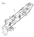
- the figure 2 presents an exemplary embodiment of an intermediate part (5) for fixing according to the invention.
- It is a rigid part preferably of plastic for example polypropylene made by molding.
- the part is substantially flat and of substantially parallelepiped shape.
- the skilled person may consider other forms such as a piece (5) U-shaped or C.
- the attachment piece (5) is intended to be placed between the vehicle structure and the rigid lining it fixes. That is why it extends mainly under this rigid lining, for example the quarter panel lining, preferably over the entire length of said lining. Nevertheless, as we will see, the intermediate attachment piece (5) can extend beyond the garnish (3) of the quarter shell that it supports and that it fixes so as to be partially under the other piece of packing (1) with which the junction is sought.
- the intermediate attachment piece (5) has a bottom (7) placed on the vehicle structure and fixed thereto. Fixing can be done in a very simple way.
- the intermediate piece (5) is placed in abutment on the vehicle structure by a protruding shape (37) in the direction of the structure and held in place by at least one stud (9) also allowing the pre-holding of the intermediate piece ( 5). It is then clamped to the structure.
- a protruding shape (37) in the direction of the structure and held in place by at least one stud (9) also allowing the pre-holding of the intermediate piece ( 5). It is then clamped to the structure.
- studs (9) on the face of the intermediate piece (5) fastening in contact with the vehicle structure. These studs (9) are intended to be inserted into keyhole-shaped recesses formed on the structure (or bodywork) of the vehicle.
- the intermediate piece (5) for fixing is held in place by a complementary fastening screw.
- the support piece (5) has at least one hole (11) allowing the passage of the screw.
- the intermediate attachment piece (5) is fixed isostatically to the vehicle structure.
- One of the advantages of the use of such an intermediate part (5) is, as we will see later, that it makes it possible to mask the fastening system to the structure since it is completely covered by the linings (1, 3). There is therefore no visible screws on the lining (3) rigid even at opposite ends to the line of junction with the second lining (1). It will also be understood that the positioning of the intermediate piece (5) on the vehicle structure is fixed and predetermined, which therefore implies that the lining (3) rigid has a fixed position too.
- the intermediate attachment piece (5) further comprises means (19) for aligning the second lining (1), or headlining, with respect to the rigid lining (3), or quarter panel trim.
- these alignment means (19) comprise at least one protrusion, for example an indexing or stopping finger (19) extending towards the interior of the vehicle and intended to allow the positioning of the roof lining (1).
- the finger (19) is placed at the junction zone.
- the finger (19) is placed in the junction zone between the two gaskets (1,3) and the lining (1) whose finger (19) limits the displacement has a cutout (27) in which the finger (19) ) is inserted or placed.
- the cutout (27) can be positioned on the end edge of the second liner (1), on the edge adjacent to the end edge joining, or in the form of a hole at the end of the liner ( 1).
- the finger (19) serves as a stop and adjusts the lateral alignment of the two liners (1, 3) to ensure the continuity of their side walls and thus improve the quality perceived by the user.
- the abutment is therefore in the plane of the rigid lining (3) or more precisely in the plane of its wall.
- the finger (19) aligns the two liners (1,3) with respect to their edges adjacent to the end edges joining the two linings (1,3).
- the second lining (1) namely the headliner, is not fastened as such to the fastener part (5) which at this stage only serves as an alignment system.
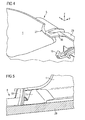
- the figure 4 illustrates the positioning of the lining (1) flag. It can be seen how the finger (19) for stopping the intermediate piece (5) attachment is placed in the cutout (27) to form a stop limiting the transverse displacement of the second lining (1), or headlining , with respect to the intermediate piece (5) and therefore with respect to the rigid lining (3).
- the finger (19) will block the position of the lining (1) flag in the direction Z relative to the reference of the vehicle.
- the intermediate attachment piece (5) is placed so as to extend under the junction zone of the two gaskets (1, 3), and preferably on either side of that -this.
- the junction of the two gaskets (1,3) is effected on the intermediate piece (5) at a protuberance (13) extending over all or part of the length from the junction area.
- the finger (19) serving as a stop will have a height greater than the height of the protuberance (13).
- the protuberance (13) is dimensioned to cooperate with the rigid lining (3) in order to clampably hold the second lining (1) since the end of the latter is placed between the intermediate piece (5) and the lining ( 3) rigid.
- the protuberance (13) will cooperate with the garnish (3) rigid quarter panel to maintain in place the lining (1) flag by sandwiching it. That is why, preferably, the protuberance (13) extends over the entire length of the junction zone.
- the intermediate piece (5) can also serve as a support for the passage of the electrical harnesses, the antenna beam or the exhaust pipe of the sunroof.
- the intermediate piece (5) is then advantageously flat and has on its bottom (7) flanges (15) for holding in place the electrical harness and / or flanges for (17) holding in place the discharge pipe of the sunroof.
- the cables and / or pipes will therefore pass between said intermediate part (5) and the rigid lining (3). Due to the assembly synoptics, namely, because the fastening piece (5) is put in place before said bundles and pipe, the protuberance (13) will not continue for the entire length of the zone junction but only on a part to leave a passage for said beams and pipe.
- the protuberance (13) extends over a portion greater than 50% in length of the junction zone between the two gaskets (1,3).
- the skilled person may also consider passing the beams and the pipe under the protuberance (13) so as to extend the contact surface between the lining (1) and the protuberance (13) to the entire junction zone .
- a passage (not shown) will then be arranged under the protrusion (13) which will then be a bridge spanning beams and pipe.
- the rigid seal (3) is then mounted. It is fixed on the intermediate piece (5) for example by clipping.
- the attachment piece (5) then has fastening means (21) able to cooperate with complementary means present on the non-visible internal face of the lining (3).
- These fixing means (21) are for example constituted by clipping boxes (21).
- the skilled person may consider any other fastening system provided that it allows isostatic attachment of the lining (3) rigid on the intermediate piece (5).
- the conventional rigid form of lining (3) and the cooperation between the fastening means of the intermediate part (5) and the lining (3) make it possible to define a given spacing between the vehicle structure and the lining wall (3). ), or more precisely between the bottom (7) or the protuberance (13) of the intermediate piece and the lining (3) rigid. This spacing, given and defined, is particularly useful as we have seen for sandwiching the second liner (1) or for the passage of elements such as cables or pipes under the rigid lining (3).
- the support part (5) may have a base (23) serving as a reinforcing zone and for stiffening. Moreover, the skilled person may consider placing a complementary clipping system (25) reinforcing the strength of the lining (3) in case of deployment of a side airbag.
- the intermediate piece (5) extends, as we have seen, longitudinally along the entire length of the rigid lining (3) and has clipping boxes regularly spaced apart, for example five in number.
- the rigid lining (3) will overlap the second lining (1) at the intermediate part (5), and that more precisely the overlap of the lining (1, 3) is at the protuberance (13) of the attachment piece (5).
- the second lining (1) is thus sandwiched between the two rigid elements that are the intermediate piece (5) and the quarter panel trim (3). This sandwiching ensures the maintenance of the lining (1) flag.
- the junction between the two gaskets (1, 3) is stiffened which minimizes the appearance or the presence of a clearance between the gaskets (1, 3) at this junction line.
- the protrusion (13) is dimensioned so that the spacing between the intermediate piece (5) and the rigid lining (3) is slightly less than the thickness of the lining (1). ) flexible so as to compress it. In this way, the clearance between the linings (1, 3) is practically zero. For example, the user can not expand it by trying to insert his fingers.
- the protrusion (13) must be able to withstand the pressure without deforming. This is why, as we can see on the figure 3 it will be advantageous to strengthen or stiffen the protuberance (13) at its hollow internal face by a series of longitudinal ribs (41).
- the intermediate piece (5) and the rigid lining (3) form a jaw, a vise, which immobilizes the second lining (1).
- the stop finger (19) of the support part (5) is covered by the rigid lining (3) in order to be hidden in view of the user.
- the assembly thus fixed reveals only the junction between the two linings (1, 3).
- the means (9) for fixing the support part (5) to the vehicle structure or for fastening (21) the rear quarter trim (3) to the attachment piece (5), or the means (19) indexing the lining (1) flag are hidden in view of the user.
- the attachment piece (5) can also act as a spacer. This is illustrated in figure 5 wherein the protuberance (13) is sized to extend slightly below the second liner (1) beyond the junction area. Indeed, it allows to define a spacing between the lining (1,3) and the structure (29) of the vehicle.
- the lining (1), flexible flag is then maintained at a given distance from the structure (29) of vehicle by a rigid structure, in this case by the protuberance (13) of the part (5) fixing.
- the assembly thus produced is such that the first lining (1) is locked in position and can not be dismounted without the lining (3) is rigid beforehand.
- the invention is not limited to the embodiments described above, given only by way of example, but encompasses all the variants that may be envisaged by those skilled in the art within the framework of the definition that has been given.
- the invention is not limited to the application of the invention at the junction of a rigid lining and a flexible liner. It can also be applied to the joining of two rigid gaskets. In such a case, the skilled person will benefit from providing at the end of the second lining a slight recess with respect to its wall allowing the second lining to fit under the rigid lining attached to the intermediate piece while ensuring continuity between the walls of the two fittings.
Landscapes
- Engineering & Computer Science (AREA)
- Mechanical Engineering (AREA)
- Vehicle Interior And Exterior Ornaments, Soundproofing, And Insulation (AREA)
Claims (13)
- Zwischenbefestigungsteil (5) einer starren Verkleidung (3) an einem Fahrzeugaufbau (29), wobei die starre Verkleidung (3) dazu bestimmt ist, an einem ihrer Enden an dem Ende einer zweiten Verkleidung (1), die sie abdeckt, zusammengefügt zu werden, indem so eine Verbindungszone definiert wird, wobei das Zwischenbefestigungsteil (5) isostatische Befestigungsmittel (9, 11) an dem Fahrzeugaufbau (29) aufweist, und Befestigungsmittel (21) an der starren Verkleidung (3), und dass es so bemessen ist, dass es sich unter der Verbindungszone zwischen den zwei Verkleidungen (1, 3) derart erstrecken kann, dass die zweite Verkleidung (1) zwischen das zwischen Verkleidungsteil (5) und die starre Verkleidung (3) nach dem Zusammenfügen eingefügt ist, und dass es außerdem Fluchtungsmittel (19) aufweist, die es erlauben, die zweite Verkleidung (1) in Bezug auf die starre Verkleidung (3) auszurichten, dadurch gekennzeichnet, dass es im Wesentlichen flach ist und auf seinem Grund (7) Flansche (15, 17) zum Halten von Kabeln und/oder Rohrleitungen aufweist, die dazu bestimmt sind, zwischen dem Zwischenverkleidungsteil (5) und der starren Verkleidung (3) durchzugehen.
- Zwischenverkleidungsteil (5) nach Anspruch 1, dadurch gekennzeichnet, dass die Fluchtungsmittel (19) mindestens einen Finger (19) aufweisen, der als Anschlag dienen kann, wobei der Finger (19) in der Verbindungszone der zwei Verkleidungen (1, 3) positioniert sein kann.
- Zwischenverkleidungsteil (5) nach einem der Ansprüche 1 bis 2, dadurch gekennzeichnet, dass die Fluchtungsmittel (19) das Ausrichten der zweiten Verkleidung (1) in Bezug auf die starre Verkleidung (3) entlang der benachbarten Ränder an ihren Enden, die die Verbindung zwischen den zwei Verkleidungen (1, 3) herstellen, erlauben.
- Zwischenverkleidungsteil (5) nach einem der Ansprüche 1 bis 3, dadurch gekennzeichnet, dass es auf seinem Teil, der dazu bestimmt ist, sich unter der Verbindungszone der zwei Verkleidungen (1, 3) zu erstrecken, einen Vorsprung (13) aufweist, der derart bemessen ist, dass er mit der starren Verkleidung (3) zusammenwirken kann, um durch Spannen die zweite Verkleidung (1), die nach dem Zusammenfügen zwischen dem Vorsprung (13) und der starren Verkleidung (3) eingeschoben platziert ist, an Ort und Stelle zu halten, wobei der Vorsprung (13) vorzugsweise derart bemessen ist, dass er einen Raum mit der starren Verkleidung (3), der leicht kleiner ist als die Stärke der zweiten Verkleidung (1), derart definieren kann, dass die zweite Verkleidung (1) zwischen dem Zwischenverkleidungsteil (5) und der starren Verkleidung (3) komprimiert ist.
- Zwischenverkleidungsteil (5) nach Anspruch 4, dadurch gekennzeichnet, dass der Vorsprung (13) geeignet ist, sich auf nur einem Teil der Länge der Verbindungszone derart zu erstrecken, dass es nach dem Zusammenfügen eine Passage zwischen dem Teil (5) und der zweiten Verkleidung (1) definiert, wobei die Passage das Durchgehen von Kabeln und/oder Rohren erlauben muss, wobei sich der Vorsprung (13) vorzugsweise auf wenigstens 50 % der Länge der Verbindungszone erstreckt.
- Zwischenverkleidungsteil (5) nach einem der Ansprüche 4 bis 5, dadurch gekennzeichnet, dass der Vorsprung (13) derart bemessen ist, dass er sich leicht über die Verbindungszone hinaus unter der zweiten Verkleidung (1) derart erstrecken kann, dass er als Abstandshalter zwischen der zweiten Verkleidung (1) und dem Aufbau des Fahrzeugs (29) dient.
- Zwischenverkleidungsteil (5) nach einem der Ansprüche 4 bis 6, dadurch gekennzeichnet, dass der Finger (19) eine Höhe aufweist, die größer ist als die Höhe des Vorsprungs (13).
- Zwischenverkleidungsteil (5) nach einem der Ansprüche 1 bis 7, dadurch gekennzeichnet, dass die Mittel (21) zum Befestigen an der Verkleidung (3) eine Befestigung durch Clipsen der starren Verkleidung (3) auf dem Zwischenverkleidungsteil (5) erlauben.
- Zwischenverkleidungsteil (5) nach einem der Ansprüche 1 bis 8, dadurch gekennzeichnet, dass es derart bemessen ist, dass es vollständig von der starren Verkleidung (3) oder durch das Zusammenfügen der starren Verkleidung (3) und der zweiten Verkleidung (1) abgedeckt werden kann.
- Zwischenverkleidungsteil (5) nach einem der Ansprüche 1 bis 9, dadurch gekennzeichnet, dass es geeignet ist, sich auf der gesamten Länge der starren Verkleidung (3) zu erstrecken, und dass die Mittel (21) zum Befestigen an der Verkleidung (3) regelmäßig beabstandet auf der gesamten Länge angeordnet sind, wobei einer der Längsränder des Teils (5) vorzugsweise ein Verstärkungselement (23), das dazu bestimmt ist, es zu versteifen, aufweist.
- Zwischenverkleidungsteil (5) nach einem der Ansprüche 1 bis 10, dadurch gekennzeichnet, dass es aus einem Kunststoff, vorzugsweise aus Polypropylen, geformt ist.
- Gebrauch eines Zwischenverkleidungsteils (5) nach einem der Ansprüche 1 bis 11 zum Befestigen einer starren Fahrzeugverkleidung (3) und seinem Verbinden mit einer zweiten Verkleidung (1), die vorzugsweise biegsam ist.
- Verfahren zur Zusammenfügebefestigung einer starren Verkleidung (3) und einer zweiten Verkleidung (1), das die folgenden Schritte aufweist:- Befestigen auf dem Aufbau (29) eines Zwischenverkleidungsteils (5) nach einem der Ansprüche 1 bis 12,- eventuell Anbringen und Befestigen von Kabeln und/oder Rohrleitungen auf dem Zwischenverkleidungsteil (5),- Positionieren der zweiten Verkleidung (1) auf dem Zwischenverkleidungsteil (5) durch Zusammenwirken des Endes der zweiten Verkleidung (1) mit den Fluchtungsmitteln (19) des Zwischenverkleidungsteils,- Befestigen der starren Verkleidung (3) auf dem Zwischenverkleidungsteil (5) derart, dass das Ende der zweiten Verkleidung (1) zwischen dem Zwischenverkleidungsteil (5) und der starren Verkleidung (3) ins Sandwich genommen ist.
Applications Claiming Priority (2)
| Application Number | Priority Date | Filing Date | Title |
|---|---|---|---|
| FR1055129A FR2961766B1 (fr) | 2010-06-28 | 2010-06-28 | Piece intermediaire de fixation de garniture de vehicule |
| PCT/FR2011/051180 WO2012001254A1 (fr) | 2010-06-28 | 2011-05-25 | Piece intermediaire de fixation de garniture de vehicule |
Publications (2)
| Publication Number | Publication Date |
|---|---|
| EP2585342A1 EP2585342A1 (de) | 2013-05-01 |
| EP2585342B1 true EP2585342B1 (de) | 2014-07-02 |
Family
ID=43437246
Family Applications (1)
| Application Number | Title | Priority Date | Filing Date |
|---|---|---|---|
| EP11726898.7A Active EP2585342B1 (de) | 2010-06-28 | 2011-05-25 | Zwischenbefestigungsteil für eine fahrzeugverkleidung |
Country Status (4)
| Country | Link |
|---|---|
| EP (1) | EP2585342B1 (de) |
| CN (1) | CN103140381B (de) |
| FR (1) | FR2961766B1 (de) |
| WO (1) | WO2012001254A1 (de) |
Families Citing this family (4)
| Publication number | Priority date | Publication date | Assignee | Title |
|---|---|---|---|---|
| FR3063051B1 (fr) * | 2017-02-21 | 2021-09-10 | Peugeot Citroen Automobiles Sa | Cadre de renfort pour garniture de pavillon integrant des languettes de fixation |
| EP3395617A1 (de) * | 2017-04-25 | 2018-10-31 | DURA Automotive Holdings U.K., Ltd. | Zierteil mit integrierter antenne |
| CN111376844A (zh) * | 2018-12-29 | 2020-07-07 | 观致汽车有限公司 | 用于车辆的车窗的饰条及饰条组件 |
| FR3103757B1 (fr) | 2019-11-28 | 2023-05-26 | Psa Automobiles Sa | Agencement de zone supérieure de custode de véhicule automobile |
Family Cites Families (7)
| Publication number | Priority date | Publication date | Assignee | Title |
|---|---|---|---|---|
| FR2742493B1 (fr) | 1995-12-19 | 1998-02-13 | Peugeot | Systeme de fixation sur un support d'un ensemble comprenant deux pieces notamment de garniture de vehicule automobile, telle que la garniture de pied milieu de celui-ci |
| JP4427879B2 (ja) * | 2000-08-11 | 2010-03-10 | 豊田合成株式会社 | ピラーガーニッシュ |
| JP2002362287A (ja) * | 2001-06-11 | 2002-12-18 | Honda Motor Co Ltd | 乗員拘束装置 |
| JP3866733B2 (ja) * | 2004-04-27 | 2007-01-10 | 本田技研工業株式会社 | 乗員拘束装置 |
| FR2888547A3 (fr) | 2005-07-13 | 2007-01-19 | Renault Sas | Agencement d'un element d'habillage sur un panneau de porte de vehicule automobile |
| JP4837578B2 (ja) * | 2007-01-23 | 2011-12-14 | 本田技研工業株式会社 | エアバッグ装置の配設構造 |
| JP4903102B2 (ja) * | 2007-09-10 | 2012-03-28 | 本田技研工業株式会社 | 車両のピラーガーニッシュ構造 |
-
2010
- 2010-06-28 FR FR1055129A patent/FR2961766B1/fr not_active Expired - Fee Related
-
2011
- 2011-05-25 WO PCT/FR2011/051180 patent/WO2012001254A1/fr active Application Filing
- 2011-05-25 CN CN201180032744.6A patent/CN103140381B/zh not_active Expired - Fee Related
- 2011-05-25 EP EP11726898.7A patent/EP2585342B1/de active Active
Also Published As
| Publication number | Publication date |
|---|---|
| CN103140381A (zh) | 2013-06-05 |
| FR2961766A1 (fr) | 2011-12-30 |
| CN103140381B (zh) | 2016-01-20 |
| FR2961766B1 (fr) | 2014-08-15 |
| WO2012001254A1 (fr) | 2012-01-05 |
| EP2585342A1 (de) | 2013-05-01 |
Similar Documents
| Publication | Publication Date | Title |
|---|---|---|
| EP2621745B1 (de) | Glasscheibe mit einem umhüllten dichtungsprofil und einem an dem dichtunfsprofil befestigten einsatz zur befestigung des einsatzes für die glasscheibe und verfahren zur herstellung der glasscheibe | |
| EP2585342B1 (de) | Zwischenbefestigungsteil für eine fahrzeugverkleidung | |
| FR2890361A1 (fr) | Insert pour caisse de vehicule automobile | |
| EP2253556A1 (de) | Transportschlüssel mit leichter Entfernbarkeit für Hohlprofile oder deformierbare Hohlteile | |
| FR2871131A1 (fr) | Ensemble de carrosserie d'un vehicule automobile | |
| FR2995861A1 (fr) | Habillage interieur structurel pour porte laterale de vehicule et porte laterale ainsi equipee | |
| EP1666309B1 (de) | Clip zur Befestigung einer Dachverkleidung eines Fahrzeuges, Einheiten aus solchen Clips und einer Dachverkleidung sowie damit ausgestattetes Fahrzeug | |
| EP2795141A1 (de) | System zum befestigen eines objekts an einem element mit befestigungsrille(n) und befestigungsvorrichtung für ein solches system | |
| EP3199405B1 (de) | Dachlastenträger für kraftfahrzeug, und entsprechendes befestigungssystem | |
| FR3070631A1 (fr) | Insert pour une coulisse de vitrage de vehicule | |
| EP2167349B1 (de) | Anordnung zur befestigung einer motorfahrzeugkarosserie-oberflächenauskleidung in der nähe einer fensterscheibe | |
| WO2016087737A1 (fr) | Agencement pour véhicule automobile comprenant un assemblage muni d'une feuillure configurée pour supporter un élément de toit | |
| FR3014791A1 (fr) | Systeme de securite pour vehicule | |
| FR3036327A1 (fr) | Ensemble doublure-pontet pour volet plastique | |
| EP1104709B1 (de) | Rollo mit Gehäuse und Halteelementen | |
| EP3898303B1 (de) | Glasscheibe mit einer verkapselten profilierten verbindung mit einem befestigten teil, das mithilfe eines hakens gesichert ist | |
| FR2956081A1 (fr) | Ensemble d'equipement de vehicule automobile et procede de montage associe. | |
| FR3054182B1 (fr) | Assemblage d'un element decoratif sur un element de garniture et un element structurel | |
| FR3104091A1 (fr) | Agencement de garnitures d’habillage destinées à être montées de manière juxtaposée au voisinage d’une portion de joint d’étanchéité | |
| FR2983167A1 (fr) | Agencement d'une garniture laterale de coffre | |
| FR3061099A1 (fr) | Assemblage renforce d'une structure d'habillage a une ouverture realisee dans une paroi de garniture d'un vehicule. | |
| EP2578892B1 (de) | Befestigungsvorrichtung mit Mutter | |
| FR2868371A1 (fr) | Ensemble de montage d'une barre de toit longitudinale sur un toit d'un vehicule automobile | |
| FR3134359A1 (fr) | Patte de fixation d’un projecteur de véhicule automobile | |
| FR3075698A1 (fr) | Ouvrant de vehicule comportant un moyen de rigidification et un dispositif d'eclairage |
Legal Events
| Date | Code | Title | Description |
|---|---|---|---|
| PUAI | Public reference made under article 153(3) epc to a published international application that has entered the european phase |
Free format text: ORIGINAL CODE: 0009012 |
|
| 17P | Request for examination filed |
Effective date: 20130125 |
|
| AK | Designated contracting states |
Kind code of ref document: A1 Designated state(s): AL AT BE BG CH CY CZ DE DK EE ES FI FR GB GR HR HU IE IS IT LI LT LU LV MC MK MT NL NO PL PT RO RS SE SI SK SM TR |
|
| DAX | Request for extension of the european patent (deleted) | ||
| GRAP | Despatch of communication of intention to grant a patent |
Free format text: ORIGINAL CODE: EPIDOSNIGR1 |
|
| INTG | Intention to grant announced |
Effective date: 20140116 |
|
| GRAS | Grant fee paid |
Free format text: ORIGINAL CODE: EPIDOSNIGR3 |
|
| GRAA | (expected) grant |
Free format text: ORIGINAL CODE: 0009210 |
|
| AK | Designated contracting states |
Kind code of ref document: B1 Designated state(s): AL AT BE BG CH CY CZ DE DK EE ES FI FR GB GR HR HU IE IS IT LI LT LU LV MC MK MT NL NO PL PT RO RS SE SI SK SM TR |
|
| REG | Reference to a national code |
Ref country code: GB Ref legal event code: FG4D Free format text: NOT ENGLISH |
|
| REG | Reference to a national code |
Ref country code: CH Ref legal event code: EP Ref country code: AT Ref legal event code: REF Ref document number: 675732 Country of ref document: AT Kind code of ref document: T Effective date: 20140715 |
|
| REG | Reference to a national code |
Ref country code: IE Ref legal event code: FG4D Free format text: LANGUAGE OF EP DOCUMENT: FRENCH |
|
| REG | Reference to a national code |
Ref country code: DE Ref legal event code: R096 Ref document number: 602011008141 Country of ref document: DE Effective date: 20140814 |
|
| REG | Reference to a national code |
Ref country code: AT Ref legal event code: MK05 Ref document number: 675732 Country of ref document: AT Kind code of ref document: T Effective date: 20140702 |
|
| REG | Reference to a national code |
Ref country code: NL Ref legal event code: VDEP Effective date: 20140702 |
|
| REG | Reference to a national code |
Ref country code: LT Ref legal event code: MG4D |
|
| PG25 | Lapsed in a contracting state [announced via postgrant information from national office to epo] |
Ref country code: LT Free format text: LAPSE BECAUSE OF FAILURE TO SUBMIT A TRANSLATION OF THE DESCRIPTION OR TO PAY THE FEE WITHIN THE PRESCRIBED TIME-LIMIT Effective date: 20140702 Ref country code: ES Free format text: LAPSE BECAUSE OF FAILURE TO SUBMIT A TRANSLATION OF THE DESCRIPTION OR TO PAY THE FEE WITHIN THE PRESCRIBED TIME-LIMIT Effective date: 20140702 Ref country code: CZ Free format text: LAPSE BECAUSE OF FAILURE TO SUBMIT A TRANSLATION OF THE DESCRIPTION OR TO PAY THE FEE WITHIN THE PRESCRIBED TIME-LIMIT Effective date: 20140702 Ref country code: NO Free format text: LAPSE BECAUSE OF FAILURE TO SUBMIT A TRANSLATION OF THE DESCRIPTION OR TO PAY THE FEE WITHIN THE PRESCRIBED TIME-LIMIT Effective date: 20141002 Ref country code: FI Free format text: LAPSE BECAUSE OF FAILURE TO SUBMIT A TRANSLATION OF THE DESCRIPTION OR TO PAY THE FEE WITHIN THE PRESCRIBED TIME-LIMIT Effective date: 20140702 Ref country code: GR Free format text: LAPSE BECAUSE OF FAILURE TO SUBMIT A TRANSLATION OF THE DESCRIPTION OR TO PAY THE FEE WITHIN THE PRESCRIBED TIME-LIMIT Effective date: 20141003 Ref country code: SE Free format text: LAPSE BECAUSE OF FAILURE TO SUBMIT A TRANSLATION OF THE DESCRIPTION OR TO PAY THE FEE WITHIN THE PRESCRIBED TIME-LIMIT Effective date: 20140702 Ref country code: PT Free format text: LAPSE BECAUSE OF FAILURE TO SUBMIT A TRANSLATION OF THE DESCRIPTION OR TO PAY THE FEE WITHIN THE PRESCRIBED TIME-LIMIT Effective date: 20141103 Ref country code: BG Free format text: LAPSE BECAUSE OF FAILURE TO SUBMIT A TRANSLATION OF THE DESCRIPTION OR TO PAY THE FEE WITHIN THE PRESCRIBED TIME-LIMIT Effective date: 20141002 |
|
| PG25 | Lapsed in a contracting state [announced via postgrant information from national office to epo] |
Ref country code: HR Free format text: LAPSE BECAUSE OF FAILURE TO SUBMIT A TRANSLATION OF THE DESCRIPTION OR TO PAY THE FEE WITHIN THE PRESCRIBED TIME-LIMIT Effective date: 20140702 Ref country code: LV Free format text: LAPSE BECAUSE OF FAILURE TO SUBMIT A TRANSLATION OF THE DESCRIPTION OR TO PAY THE FEE WITHIN THE PRESCRIBED TIME-LIMIT Effective date: 20140702 Ref country code: AT Free format text: LAPSE BECAUSE OF FAILURE TO SUBMIT A TRANSLATION OF THE DESCRIPTION OR TO PAY THE FEE WITHIN THE PRESCRIBED TIME-LIMIT Effective date: 20140702 Ref country code: NL Free format text: LAPSE BECAUSE OF FAILURE TO SUBMIT A TRANSLATION OF THE DESCRIPTION OR TO PAY THE FEE WITHIN THE PRESCRIBED TIME-LIMIT Effective date: 20140702 Ref country code: PL Free format text: LAPSE BECAUSE OF FAILURE TO SUBMIT A TRANSLATION OF THE DESCRIPTION OR TO PAY THE FEE WITHIN THE PRESCRIBED TIME-LIMIT Effective date: 20140702 Ref country code: CY Free format text: LAPSE BECAUSE OF FAILURE TO SUBMIT A TRANSLATION OF THE DESCRIPTION OR TO PAY THE FEE WITHIN THE PRESCRIBED TIME-LIMIT Effective date: 20140702 Ref country code: RS Free format text: LAPSE BECAUSE OF FAILURE TO SUBMIT A TRANSLATION OF THE DESCRIPTION OR TO PAY THE FEE WITHIN THE PRESCRIBED TIME-LIMIT Effective date: 20140702 Ref country code: IS Free format text: LAPSE BECAUSE OF FAILURE TO SUBMIT A TRANSLATION OF THE DESCRIPTION OR TO PAY THE FEE WITHIN THE PRESCRIBED TIME-LIMIT Effective date: 20141102 |
|
| REG | Reference to a national code |
Ref country code: DE Ref legal event code: R084 Ref document number: 602011008141 Country of ref document: DE |
|
| REG | Reference to a national code |
Ref country code: DE Ref legal event code: R097 Ref document number: 602011008141 Country of ref document: DE |
|
| REG | Reference to a national code |
Ref country code: GB Ref legal event code: 746 Effective date: 20150330 |
|
| REG | Reference to a national code |
Ref country code: DE Ref legal event code: R084 Ref document number: 602011008141 Country of ref document: DE Effective date: 20150307 |
|
| PG25 | Lapsed in a contracting state [announced via postgrant information from national office to epo] |
Ref country code: SK Free format text: LAPSE BECAUSE OF FAILURE TO SUBMIT A TRANSLATION OF THE DESCRIPTION OR TO PAY THE FEE WITHIN THE PRESCRIBED TIME-LIMIT Effective date: 20140702 Ref country code: IT Free format text: LAPSE BECAUSE OF FAILURE TO SUBMIT A TRANSLATION OF THE DESCRIPTION OR TO PAY THE FEE WITHIN THE PRESCRIBED TIME-LIMIT Effective date: 20140702 Ref country code: DK Free format text: LAPSE BECAUSE OF FAILURE TO SUBMIT A TRANSLATION OF THE DESCRIPTION OR TO PAY THE FEE WITHIN THE PRESCRIBED TIME-LIMIT Effective date: 20140702 Ref country code: EE Free format text: LAPSE BECAUSE OF FAILURE TO SUBMIT A TRANSLATION OF THE DESCRIPTION OR TO PAY THE FEE WITHIN THE PRESCRIBED TIME-LIMIT Effective date: 20140702 Ref country code: RO Free format text: LAPSE BECAUSE OF FAILURE TO SUBMIT A TRANSLATION OF THE DESCRIPTION OR TO PAY THE FEE WITHIN THE PRESCRIBED TIME-LIMIT Effective date: 20140702 |
|
| PLBE | No opposition filed within time limit |
Free format text: ORIGINAL CODE: 0009261 |
|
| STAA | Information on the status of an ep patent application or granted ep patent |
Free format text: STATUS: NO OPPOSITION FILED WITHIN TIME LIMIT |
|
| 26N | No opposition filed |
Effective date: 20150407 |
|
| PG25 | Lapsed in a contracting state [announced via postgrant information from national office to epo] |
Ref country code: SI Free format text: LAPSE BECAUSE OF FAILURE TO SUBMIT A TRANSLATION OF THE DESCRIPTION OR TO PAY THE FEE WITHIN THE PRESCRIBED TIME-LIMIT Effective date: 20140702 |
|
| REG | Reference to a national code |
Ref country code: CH Ref legal event code: PL |
|
| PG25 | Lapsed in a contracting state [announced via postgrant information from national office to epo] |
Ref country code: CH Free format text: LAPSE BECAUSE OF NON-PAYMENT OF DUE FEES Effective date: 20150531 Ref country code: LU Free format text: LAPSE BECAUSE OF FAILURE TO SUBMIT A TRANSLATION OF THE DESCRIPTION OR TO PAY THE FEE WITHIN THE PRESCRIBED TIME-LIMIT Effective date: 20150525 Ref country code: LI Free format text: LAPSE BECAUSE OF NON-PAYMENT OF DUE FEES Effective date: 20150531 Ref country code: MC Free format text: LAPSE BECAUSE OF FAILURE TO SUBMIT A TRANSLATION OF THE DESCRIPTION OR TO PAY THE FEE WITHIN THE PRESCRIBED TIME-LIMIT Effective date: 20140702 |
|
| REG | Reference to a national code |
Ref country code: IE Ref legal event code: MM4A |
|
| REG | Reference to a national code |
Ref country code: FR Ref legal event code: PLFP Year of fee payment: 6 |
|
| PG25 | Lapsed in a contracting state [announced via postgrant information from national office to epo] |
Ref country code: IE Free format text: LAPSE BECAUSE OF NON-PAYMENT OF DUE FEES Effective date: 20150525 |
|
| PG25 | Lapsed in a contracting state [announced via postgrant information from national office to epo] |
Ref country code: MT Free format text: LAPSE BECAUSE OF FAILURE TO SUBMIT A TRANSLATION OF THE DESCRIPTION OR TO PAY THE FEE WITHIN THE PRESCRIBED TIME-LIMIT Effective date: 20140702 |
|
| REG | Reference to a national code |
Ref country code: FR Ref legal event code: PLFP Year of fee payment: 7 |
|
| PG25 | Lapsed in a contracting state [announced via postgrant information from national office to epo] |
Ref country code: HU Free format text: LAPSE BECAUSE OF FAILURE TO SUBMIT A TRANSLATION OF THE DESCRIPTION OR TO PAY THE FEE WITHIN THE PRESCRIBED TIME-LIMIT; INVALID AB INITIO Effective date: 20110525 Ref country code: SM Free format text: LAPSE BECAUSE OF FAILURE TO SUBMIT A TRANSLATION OF THE DESCRIPTION OR TO PAY THE FEE WITHIN THE PRESCRIBED TIME-LIMIT Effective date: 20140702 |
|
| PG25 | Lapsed in a contracting state [announced via postgrant information from national office to epo] |
Ref country code: BE Free format text: LAPSE BECAUSE OF NON-PAYMENT OF DUE FEES Effective date: 20150531 |
|
| PG25 | Lapsed in a contracting state [announced via postgrant information from national office to epo] |
Ref country code: TR Free format text: LAPSE BECAUSE OF FAILURE TO SUBMIT A TRANSLATION OF THE DESCRIPTION OR TO PAY THE FEE WITHIN THE PRESCRIBED TIME-LIMIT Effective date: 20140702 |
|
| REG | Reference to a national code |
Ref country code: FR Ref legal event code: PLFP Year of fee payment: 8 |
|
| PG25 | Lapsed in a contracting state [announced via postgrant information from national office to epo] |
Ref country code: MK Free format text: LAPSE BECAUSE OF FAILURE TO SUBMIT A TRANSLATION OF THE DESCRIPTION OR TO PAY THE FEE WITHIN THE PRESCRIBED TIME-LIMIT Effective date: 20140702 |
|
| REG | Reference to a national code |
Ref country code: FR Ref legal event code: CA Effective date: 20180312 Ref country code: FR Ref legal event code: CD Owner name: PEUGEOT CITROEN AUTOMOBILES SA, FR Effective date: 20180312 |
|
| PGFP | Annual fee paid to national office [announced via postgrant information from national office to epo] |
Ref country code: DE Payment date: 20180419 Year of fee payment: 8 |
|
| PG25 | Lapsed in a contracting state [announced via postgrant information from national office to epo] |
Ref country code: AL Free format text: LAPSE BECAUSE OF FAILURE TO SUBMIT A TRANSLATION OF THE DESCRIPTION OR TO PAY THE FEE WITHIN THE PRESCRIBED TIME-LIMIT Effective date: 20140702 |
|
| PGFP | Annual fee paid to national office [announced via postgrant information from national office to epo] |
Ref country code: GB Payment date: 20180419 Year of fee payment: 8 |
|
| REG | Reference to a national code |
Ref country code: DE Ref legal event code: R119 Ref document number: 602011008141 Country of ref document: DE |
|
| GBPC | Gb: european patent ceased through non-payment of renewal fee |
Effective date: 20190525 |
|
| PG25 | Lapsed in a contracting state [announced via postgrant information from national office to epo] |
Ref country code: GB Free format text: LAPSE BECAUSE OF NON-PAYMENT OF DUE FEES Effective date: 20190525 Ref country code: DE Free format text: LAPSE BECAUSE OF NON-PAYMENT OF DUE FEES Effective date: 20191203 |
|
| PGFP | Annual fee paid to national office [announced via postgrant information from national office to epo] |
Ref country code: FR Payment date: 20230420 Year of fee payment: 13 |