EP2583816A1 - Verfahren zum Betreiben einer Vorrichtung zum Prägen - Google Patents
Verfahren zum Betreiben einer Vorrichtung zum Prägen Download PDFInfo
- Publication number
- EP2583816A1 EP2583816A1 EP12186204.9A EP12186204A EP2583816A1 EP 2583816 A1 EP2583816 A1 EP 2583816A1 EP 12186204 A EP12186204 A EP 12186204A EP 2583816 A1 EP2583816 A1 EP 2583816A1
- Authority
- EP
- European Patent Office
- Prior art keywords
- tool
- embossing
- actuator
- die
- motors
- Prior art date
- Legal status (The legal status is an assumption and is not a legal conclusion. Google has not performed a legal analysis and makes no representation as to the accuracy of the status listed.)
- Granted
Links
Images


Classifications
-
- B—PERFORMING OPERATIONS; TRANSPORTING
- B31—MAKING ARTICLES OF PAPER, CARDBOARD OR MATERIAL WORKED IN A MANNER ANALOGOUS TO PAPER; WORKING PAPER, CARDBOARD OR MATERIAL WORKED IN A MANNER ANALOGOUS TO PAPER
- B31F—MECHANICAL WORKING OR DEFORMATION OF PAPER, CARDBOARD OR MATERIAL WORKED IN A MANNER ANALOGOUS TO PAPER
- B31F1/00—Mechanical deformation without removing material, e.g. in combination with laminating
- B31F1/07—Embossing, i.e. producing impressions formed by locally deep-drawing, e.g. using rolls provided with complementary profiles
-
- B—PERFORMING OPERATIONS; TRANSPORTING
- B31—MAKING ARTICLES OF PAPER, CARDBOARD OR MATERIAL WORKED IN A MANNER ANALOGOUS TO PAPER; WORKING PAPER, CARDBOARD OR MATERIAL WORKED IN A MANNER ANALOGOUS TO PAPER
- B31B—MAKING CONTAINERS OF PAPER, CARDBOARD OR MATERIAL WORKED IN A MANNER ANALOGOUS TO PAPER
- B31B50/00—Making rigid or semi-rigid containers, e.g. boxes or cartons
- B31B50/006—Controlling; Regulating; Measuring; Improving safety
-
- B—PERFORMING OPERATIONS; TRANSPORTING
- B31—MAKING ARTICLES OF PAPER, CARDBOARD OR MATERIAL WORKED IN A MANNER ANALOGOUS TO PAPER; WORKING PAPER, CARDBOARD OR MATERIAL WORKED IN A MANNER ANALOGOUS TO PAPER
- B31B—MAKING CONTAINERS OF PAPER, CARDBOARD OR MATERIAL WORKED IN A MANNER ANALOGOUS TO PAPER
- B31B50/00—Making rigid or semi-rigid containers, e.g. boxes or cartons
- B31B50/74—Auxiliary operations
- B31B50/88—Printing; Embossing
-
- B—PERFORMING OPERATIONS; TRANSPORTING
- B31—MAKING ARTICLES OF PAPER, CARDBOARD OR MATERIAL WORKED IN A MANNER ANALOGOUS TO PAPER; WORKING PAPER, CARDBOARD OR MATERIAL WORKED IN A MANNER ANALOGOUS TO PAPER
- B31F—MECHANICAL WORKING OR DEFORMATION OF PAPER, CARDBOARD OR MATERIAL WORKED IN A MANNER ANALOGOUS TO PAPER
- B31F2201/00—Mechanical deformation of paper or cardboard without removing material
- B31F2201/07—Embossing
- B31F2201/0707—Embossing by tools working continuously
- B31F2201/0715—The tools being rollers
- B31F2201/0741—Roller cooperating with a non-even counter roller
- B31F2201/0743—Roller cooperating with a non-even counter roller having a matching profile
-
- B—PERFORMING OPERATIONS; TRANSPORTING
- B31—MAKING ARTICLES OF PAPER, CARDBOARD OR MATERIAL WORKED IN A MANNER ANALOGOUS TO PAPER; WORKING PAPER, CARDBOARD OR MATERIAL WORKED IN A MANNER ANALOGOUS TO PAPER
- B31F—MECHANICAL WORKING OR DEFORMATION OF PAPER, CARDBOARD OR MATERIAL WORKED IN A MANNER ANALOGOUS TO PAPER
- B31F2201/00—Mechanical deformation of paper or cardboard without removing material
- B31F2201/07—Embossing
- B31F2201/0707—Embossing by tools working continuously
- B31F2201/0715—The tools being rollers
- B31F2201/0753—Roller supporting, positioning, driving means
Definitions
- the present invention relates to a method for operating a device for embossing, wherein a tool in the form of a male cooperates with a tool in the form of a die, one tool is driven by a motor and the other tool by another motor and the motors to each other be electronically synchronized.
- Rotary embossing devices are used for embossing Braille Braille in cardboard sheets from which cartons, z. B. for pharmaceuticals.
- the die and male are each rotationally driven by a motor.
- the die and the male must be synchronized with each other, which can be done either via a gear connection mechanically or via an electronic synchronization of the motors.
- a scoring device in which one scoring roll with dies and the other scoring roll is equipped with male.
- the creasing rollers can be electronically or mechanically synchronized. To set different radii of the creasing tools and to be able to process materials of different thickness, the axial distance between the two creasing rollers is adjustable.
- a device for embossing braille Braille is described.
- the device has embossing rollers, each driven by a motor.
- the motors are each assigned a pulse generator. With the help of the pulse generators, an angular position deviation of the tool rolls can be detected.
- One of the embossing rollers is mounted in a housing which is sprung and vertically movable. This avoids otherwise caused tool damage by exceptionally thick cardboard sheet.
- the object of the invention is to reliably avoid component damage caused by synchronous running deviations.
- the method according to the invention for operating a device for embossing wherein a tool in the form of a male part cooperates with a tool in the form of a die, one tool is driven by a motor and the other by another motor and the motors are electronically synchronized with each other, is characterized in that a synchronous operation of the motors with respect to occurring deviations is monitored by means of at least one angular position sensor, and that when an inadmissibly large deviation occurs by means of an actuator automatically one of the tools is moved away from the other tools to avoid component damage.
- the actuator is a piezoelectric actuator. This is advantageous in terms of a quasi-sudden reaction to the occurrence of impermissibly large deviation.
- the piezo actuator By means of the piezo actuator, one tool can be adjusted extremely quickly away from the other tool in order to avoid component damage.
- the monitoring of the synchronous operation of the motors with respect to occurring deviations is carried out by means of two angular position sensors, each of which is assigned to a different one of the motors. If the motors are connected to each other via a so-called sequential control, a single angular position sensor is sufficient to monitor the synchronous operation.
- the tools are Braille embossing tools, that is, embossing tools for embossing Braille Braille points.
- the invention also includes a control device which is programmed to carry out the method according to the invention or one of its developments.
- the invention includes an embossing device equipped with such a control device and a folding box gluing machine equipped with such an embossing device.
- FIGS. 1 to 7 are mutually corresponding elements and components designated by the same reference numerals.
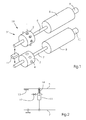
- FIG. 1 shows an embossing device 24 for rotary embossing Braille Braille.
- the embossing device 24 is part of a folding box gluing machine 19 and comprises a male part 1 with stamps 2 and a die 3 with holes 4.
- the stamp 2 press the embossing of the points the material in the holes 4.
- the stamp 2 are part of a product-specific tool and in the the desired Braille symbol corresponding number and arrangement available.
- the tool is a stamping plate, which is mounted on the male part 1. If another job requires another Braille icon, the tool will be substituted for another one.
- the holes 4 are available in arrangement required for all Braille symbols in order, so that the die 3 can be used universally.
- the male part 1 is rotatably connected via a first shaft 5 with a first motor 6.
- the die 2 is rotatably connected via a second shaft 7 with a second motor 8.
- the motors 6, 8 are direct drives and via an electronic control device 20 (see. FIG. 7 ) synchronized with each other.
- the synchronous operation of the shafts 5, 7 and thus the male part 1 and the die 3 is purely control technology and not by the positive connection geared by gears or the like.
- Connected to the control device are a first angular position transmitter 9 assigned to the first motor 6 and a second angular position sensor 10 assigned to the second motor 8.
- the die 3, the second shaft 7 and the second motor 8 form a stationarily mounted, second unit.
- a first unit is formed by the male part 1, the first shaft 5 and the first motor 6 and is adjustably mounted relative to the second unit depending on the thickness of the material to be embossed.
- a mutually reversed arrangement of the male part 1 and the die 3, wherein the male part 1 as a part of the second unit on the second shaft 7 sat and the female 3 as part of the first unit on the first shaft 5, is also possible. This also applies to all embodiments explained below.
- the adjustment of the first unit to and from the second unit takes place vertically and is driven by an actuator or actuator 11.
- the actuator 11 is in FIG. 1 indicated schematically.
- FIGS. 2 to 5 show various embodiments of the actuator 11 FIG. 1 ,
- the actuator 11 is a pneumatic working cylinder.
- a pressurizable with compressed air expansion chamber of the actuator 11 is vented via a valve 12.
- the valve 12 is closed and the expansion chamber acted upon with compressed air, so that the actuator 11 presses the first unit together with the first shaft 5 against a stop 13. This is done against the action of a biased return spring 14.
- the stop 13 may be a screw and is adjustable depending on the thickness of the material to be embossed.
- the control device opens the valve 12, so that the expansion chamber is vented via it.
- the return spring 14 lifts the male 1 from the die 3 and the punch 2 is disengaged from the holes 4.
- the too big asynchronicity the male part 1 and the die 3 to each other detects the control device on the basis of the signals transmitted by the angular position sensors 9, 10.
- Actuator 11 is a pneumatic working cylinder which is double-acting.
- pressurizing an expansion chamber is caused that the actuator 11 pulls the first unit together with the first shaft 5 against the adjustable stop 13.
- the depth of engagement of the male in the die 3 is defined.
- the piston rod of the actuator 11 is clamped by means of a locking cartridge 15.
- the expansion chamber is vented and the other expansion chamber pressurized with compressed air, so that the actuator 11 strives to extend its piston rod. In trouble-free synchronous operation this extension is prevented by the locking cartridge 15.
- the control device releases the locking cartridge 15 so that the piston rod extends abruptly and the actuator 11 thereby lifts the male part 1 out of engagement with the female part 3.
- the actuator 11 is an electromagnetic actuator with a linearly movable armature.
- the actuator 11 engages a leg of a toggle lever 16, via which the first unit including its first shaft 5 is connected to the second unit including its second shaft 7.
- the return spring 14 engages, which pulls the first unit against the stop 13 with each other sufficiently synchronous running of the male part 1 and the die 3.
- the control device controls the actuator 11 so that it is activated and extends and the first unit together with the male part 1 (see FIG. FIG. 1 ) of the second unit together with the die 3 (see. FIG. 1 ) moved away.
- This movement of the first unit is performed by a linear guide 17 and against the force of the return spring 14.
- the movement has the result that the male part 1 is disengaged from the die 3 and between the male part 1 and the die 3, a sufficient gap is created ,
- the first unit including the first shaft and the male part 1 is connected to the second unit including the second shaft 7 and the die 3 via a piezo actuator acting as the actuator 11.
- the actuator 11 is used in interference-free synchronous operation as a support for the first unit, so that in this embodiment, the present in the other embodiments stop 13 (see FIG. FIGS. 2 to 4 ) has been omitted.
- the control device acts on the actuator 11 in accordance with the respective required thickness of the material to be embossed with an analog electrical voltage. Depending on the respective magnitude of the voltage, the actuator 11 moves more or less far, so that in this way a continuous material thickness adjustment (eg paper thickness adjustment) of one embossing tool relative to the other, here the male 1 relative to the die 3 , given is.
- the controller controls the size of the electrical voltage applied to the actuator 11, so that the actuator 11, the first unit together with the first shaft 5 and the seated thereon Male part 1 abruptly (eg, in about 1 millisecond) by a required amount (eg, about 0.2 millimeters) moved away from the second unit.
- a required amount eg, about 0.2 millimeters
- FIG. 6 shows that in trouble-free synchronous operation in the processing of the material 18, the punch 2 dips into the holes 4. At this time, the punches 2 move in the area of the holes 4 to below the peripheral line of the die 3. In this combing of the tools with each other, the material 18 is pressed by the punches 2 in the holes 4 to produce the Braille points.
- FIG. 7 schematically shows the already mentioned several times controller 20 and a flow chart, according to which the controller 20, the motors 6, 8 and the actuator 11 in all in the FIGS. 1 to 6 illustrated embodiments controls.
- a first step 21 the motors 6, 8 are synchronized with each other electronically.
- a second step 22 an impermissible synchronism deviation of the motors 6, 8 is measured by means of the angular position sensors 9, 10.
- a third step 23 the male part 1 is moved away from the die 3 to an uncritical distance by the actuator 11.
Landscapes
- Engineering & Computer Science (AREA)
- Mechanical Engineering (AREA)
- Machines For Manufacturing Corrugated Board In Mechanical Paper-Making Processes (AREA)
- Making Paper Articles (AREA)
Abstract
Description
- Die vorliegende Erfindung betrifft ein Verfahren zum Betreiben einer Vorrichtung zum Prägen, wobei ein Werkzeug in Form einer Patrize mit einem Werkzeug in Form einer Matrize zusammenarbeitet, das eine Werkzeug durch einen Motor und das andere Werkzeug durch einen anderen Motor rotativ angetrieben wird und die Motoren zueinander elektronisch synchronisiert werden.
- Rotationsprägevorrichtungen werden zum Prägen der Blindenschrift Braille in Kartonbögen verwendet, aus denen Faltschachteln, z. B. für Pharmazeutika, gefertigt werden.
- Bei solchen und ähnlichen Vorrichtungen werden die Matrize und die Patrize jeweils durch einen Motor rotativ angetrieben. Die Matrize und die Patrize müssen miteinander synchronisiert werden, was entweder über eine Zahnradverbindung mechanisch oder über eine elektronische Synchronisation der Motoren erfolgen kann.
- In
DE 10 2007 044 217 A1 ist eine Rotationsprägevorrichtung beschrieben, bei welcher die Patrize und die Matrize durch das Ineinandergreifen von Zahnkränzen synchronisiert werden. Eine Patrizenwelle ist höhenverstellbar und kann mittels eines Piezo-Aktors bewegt werden. - In
EP 1 447 211 B1 ist eine Rillvorrichtung beschrieben, bei welcher die eine Rillwalze mit Matrizen und die andere Rillwalze mit Patrizen ausgestattet ist. Die Rillwalzen können elektronisch oder mechanisch synchronisiert sein. Um unterschiedliche Radien der Rillwerkzeuge einzustellen und Materialien unterschiedlicher Dicke bearbeiten zu können, ist der Achsabstand zwischen den beiden Rillwalzen einstellbar. - In
EP 1 527 920 B1 ist eine Vorrichtung beschrieben, bei welcher die Werkzeugwalzen durch Motoren angetrieben werden, die elektronisch synchronisiert sind. Walzenlagerböcke lassen sich in Abhängigkeit vom Walzendurchmesser mittels eines Aktors vertikal einstellen. - In
US 7,651,454 B2 ist eine Vorrichtung zum Prägen der Blindenschrift Braille beschrieben. Die Vorrichtung hat Prägewalzen, die jeweils durch einen Motor angetrieben werden. Den Motoren ist jeweils ein Pulsgenerator zugeordnet. Mit Hilfe der Pulsgeneratoren lässt sich eine Winkellage-Abweichung der Werkzeugwalzen detektieren. Eine der Prägewalzen ist in einem Gehäuse gelagert, welches gefedert und vertikal verfahrbar ist. Dadurch werden durch außergewöhnlich dicke Kartonbogen sonst verursachte Werkzeugschäden vermieden. - Bei keinem Stand der Technik werden durch Synchronlaufabweichungen verursachte Bauteilbeschädigungen hinreichend sicher vermieden.
- Deshalb liegt der Erfindung die Aufgabe zugrunde, durch Synchronlaufabweichungen sonst verursachte Bauteilbeschädigungen sicher zu vermeiden.
- Diese Aufgabe wird durch ein Verfahren mit den Merkmalen des Anspruchs 1 gelöst. Das erfindungsgemäße Verfahren zum Betreiben einer Vorrichtung zum Prägen, wobei ein Werkzeug in Form einer Patrize mit einem Werkzeug in Form einer Matrize zusammenarbeitet, das eine Werkzeug durch einen Motor und das andere durch einen anderen Motor rotativ angetrieben wird und die Motoren zueinander elektronisch synchronisiert werden, ist dadurch gekennzeichnet, dass ein Synchronlauf der Motoren bezüglich auftretender Abweichungen mittels mindestens eines Winkellagegebers überwacht wird, und dass bei einem Auftreten einer unzulässig großen Abweichung mittels eines Aktors automatisch eines der Werkzeuge von dem anderen Werkzeugen weg verstellt wird, um Bauteilbeschädigungen zu vermeiden.
- Bei dem erfindungsgemäßen Verfahren werden Störfälle sicher erkannt und Schutzmaßnahmen zwangsläufig eingeleitet.
- In den Unteransprüchen sind vorteilhafte Weiterbildungen des erfindungsgemäßen Verfahrens genannt.
- Bei einer Weiterbildung wird bei dem Verstellen des einen Werkzeugs von dem anderen Werkzeug weg zwischen diesen beiden Werkzeugen ein so großer Abstand geschaffen, dass die Patrize außer Eingriff in die Matrize gelangt. Dies ist bei einem Verfahren zweckmäßig, bei welchem im störungsfreien Synchronlauf beim Prägen die Patrize in die Matrize eingreift. Dieses Eingreifen kann dadurch geschehen, dass Stempel der Patrize in Löcher der Matrize während der Werkzeugrotation vorübergehend eintauchen.
- Bei einer weiteren Weiterbildung ist der Aktor ein Piezo-Aktor. Dies ist hinsichtlich einer quasi schlagartigen Reaktion auf das Auftreten der unzulässig großen Abweichung vorteilhaft. Mittels des Piezo-Aktors kann das eine Werkzeug extrem reaktionsschnell von dem anderen Werkzeug weg verstellt werden, um die Bauteilbeschädigungen zu vermeiden.
- Bei einer weiteren Weiterbildung wird die Überwachung des Synchronlaufs der Motoren bezüglich auftretender Abweichungen mittels zweier Winkellagegeber durchgeführt, von denen jeder einem anderen der Motoren zugeordnet ist. Sind die Motoren über eine sogenannte Folgesteuerung miteinander verbunden, reicht zur Überwachung des Synchronlaufs ein einziger Winkellagegeber aus.
- Bei einer weiteren Weiterbildung sind die Werkzeuge Braille-Prägewerkzeuge, d.h., Prägewerkzeuge zum Prägen der Punkte der Braille-Blindenschrift.
- Zur Erfindung gehärt auch eine Steuereinrichtung, die zur Durchführung des erfindungsgemäßen Verfahrens oder einer seiner Weiterbildungen programmiert ist. Außerdem gehört zur Erfindung eine mit einer solchen Steuereinrichtung ausgestattete Prägevorrichtung und eine mit einer solchen Prägevorrichtung ausgestattete Faltschachtelklebemaschine.
- Weitere konstruktive und funktionelle vorteilhafte Weiterbildungen der Erfindung ergeben sich aus der nachfolgenden Beschreibung vorteilhafter Ausführungsbeispiele und der dazugehörigen Zeichnung.
- In dieser zeigt:
- Figur 1
- eine Rotationsprägevorrichtung mit einer Matrizenwelle und einer Patrizenwelle, die durch einen Aktor von der Matrizenwelle weg verstellbar ist,
- Figuren 2-5
- verschiedene Ausbildungen des Aktors aus
Figur 1 - Figur 6
- das Eindringen der Patrize in die Matrize beim Prägen, und
- Figur 7
- ein Ablaufdiagramm der Schritte eines Verfahrens zum Betreiben der Rotationsprägevorrichtung aus
Figur 1 . - In den
Figuren 1 bis 7 sind einander entsprechende Elemente und Bauteile mit den gleichen Bezugszeichen bezeichnet. -
Figur 1 zeigt eine Prägevorrichtung 24 zum rotativen Prägen von Braille-Blindenschrift. Die Prägevorrichtung 24 ist Bestandteil einer Faltschachtelklebemaschine 19 und umfasst eine Patrize 1 mit Stempeln 2 und eine Matrize 3 mit Löchern 4. Die Stempel 2 drücken beim Prägen der Punkte das Material in die Löcher 4. Die Stempel 2 sind Bestandteil eines produktspezifischen Werkzeugs und in der dem gewünschten Braille-Symbol entsprechenden Anzahl und Anordnung vorhanden. Das Werkzeug ist ein Prägeblech, das auf der Patrize 1 befestigt ist. Erfordert ein anderer Job ein anderes Braille-Symbol, wird das Werkzeug gegen ein anderes ausgewechselt. Die Löcher 4 sind in für alle Braille-Symbole erforderlicher Anzahl in Anordnung vorhanden, so dass die Matrize 3 universell einsetzbar ist. - Die Patrize 1 ist über eine erste Welle 5 mit einem ersten Motor 6 drehfest verbunden. Die Matrize 2 ist über eine zweite Welle 7 mit einem zweiten Motor 8 drehfest verbunden. Die Motoren 6, 8 sind Direktantriebe und über eine elektronische Steuereinrichtung 20 (vgl.
Figur 7 ) miteinander synchronisiert. Der Synchronlauf der Wellen 5, 7 und somit der Patrize 1 und der Matrize 3 ist rein steuerungstechnisch und nicht durch den Formschluss von Zahnrädern oder dergleichen getriebetechnisch gesichert. Mit der Steuereinrichtung verbunden sind ein dem ersten Motor 6 zugeordneter, erster Winkellagegeber 9 und ein dem zweiten Motor 8 zugeordneter, zweiter Winkellagegeber 10. - Die Matrize 3, die zweite Welle 7 und der zweite Motor 8 bilden eine ortsfest gelagerte, zweite Einheit. Eine erste Einheit wird durch die Patrize 1, die erste Welle 5 und den ersten Motor 6 gebildet und ist relativ zur zweiten Einheit in Abhängigkeit von der Dicke des zu prägenden Materials verstellbar gelagert.
- Eine gegeneinander vertauschte Anordnung der Patrize 1 und der Matrize 3, wobei die Patrize 1 als Bestandteil der zweiten Einheit auf der zweiten Welle 7 säße und die Matrize 3 als Bestandteil der ersten Einheit auf der ersten Welle 5 säße, ist ebenfalls möglich. Dies gilt auch für sämtliche nachfolgend noch erläuterte Ausführungsbeispiele.
- Das zur und von der zweiten Einheit hin und weg erfolgende Verstellen der ersten Einheit erfolgt vertikal und durch einen Stellantrieb oder Aktor 11 angetrieben. Der Aktor 11 ist in
Figur 1 schematisch angedeutet. - Die
Figuren 2 bis 5 zeigen verschiedene Ausführungsbeispiele des Aktors 11 ausFigur 1 . - Gemäß
Figur 2 ist der Aktor 11 ein pneumatischer Arbeitszylinder. Eine mit Druckluft beaufschlagbare Expansionskammer des Aktors 11 ist über ein Ventil 12 entlüftbar. Bei störungsfreiem Maschinenlauf ist das Ventil 12 geschlossen und die Expansionskammer mit Druckluft beaufschlagt, so dass der Aktor 11 die erste Einheit mitsamt der ersten Welle 5 gegen einen Anschlag 13 drückt. Dies geschieht gegen die Wirkung einer unter Vorspannung stehenden Rückstellfeder 14. Der Anschlag 13 kann eine Schraube sein und ist in Abhängigkeit von der Dicke des zu prägenden Materials justierbar. Bei einem Winkellagefehler öffnet die Steuereinrichtung das Ventil 12, so dass über dieses die Expansionskammer entlüftet wird. Infolgedessen hebt die Rückstellfeder 14 die Patrize 1 von der Matrize 3 ab und die Stempel 2 außer Eingriff in die Löcher 4. Somit kann der Winkellagefehler nicht zu einer Bauteilbeschädigung führen. Die zu große Asynchronizität der Patrize 1 und der Matrize 3 zueinander erkennt die Steuereinrichtung anhand der ihr von den Winkellagegebern 9, 10 übermittelten Signale. - Gemäß
Figur 3 ist der Aktor 11 ein pneumatischer Arbeitszylinder, der doppeltwirkend ist. Durch Druckluftbeaufschlagung der einen Expansionskammer wird bewirkt, dass der Aktor 11 die erste Einheit mitsamt der ersten Welle 5 gegen den justierbaren Anschlag 13 zieht. Dadurch ist die Tiefe des Eingriffs der Patrize in die Matrize 3 definiert. Wenn die erste Einheit am Anschlag 13 anliegt, wird mittels einer Feststellpatrone 15 die Kolbenstange des Aktors 11 festgeklemmt. Danach wird die Expansionskammer entlüftet und die andere Expansionskammer mit Druckluft beaufschlagt, so dass der Aktor 11 bestrebt ist, seine Kolbenstange auszufahren. Im störungsfreien Synchronlauf wird dieses Ausfahren durch die Feststellpatrone 15 verhindert. Bei Auftreten einer nicht tolerablen Synchronlaufabweichung löst die Steuereinrichtung die Feststellpatrone 15, so dass die Kolbenstange schlagartig ausfährt und der Aktor 11 dadurch die Patrize 1 außer Eingriff in die Matrize 3 hebt. - Gemäß
Figur 4 ist der Aktor 11 ein elektromagnetischer Aktor mit einem linear bewegbaren Anker. Der Aktor 11 greift an einem Schenkel eines Kniehebels 16 an, über welchen die erste Einheit einschließlich ihrer ersten Welle 5 mit der zweiten Einheit einschließlich ihrer zweiten Welle 7 verbunden ist. An dem anderen Schenkel des Kniehebels 16 greift die Rückstellfeder 14 an, welche bei miteinander hinreichend synchronem Lauf der Patrize 1 und der Matrize 3 die erste Einheit gegen den Anschlag 13 zieht. Beim Auftreten der Synchronlaufstörung steuert die Steuereinrichtung den Aktor 11 so an, dass dieser aktiviert wird und ausfährt und die erste Einheit mitsamt der Patrize 1 (vgl.Figur 1 ) von der zweiten Einheit mitsamt der Matrize 3 (vgl.Figur 1 ) weg bewegt. Diese Bewegung der ersten Einheit erfolgt durch eine Linearführung 17 geführt und gegen die Kraft der Rückstellfeder 14. Die Bewegung hat zur Folge, dass die Patrize 1 außer Eingriff in die Matrize 3 gelangt und zwischen der Patrize 1 und der Matrize 3 ein hinreichendes Spaltmaß geschaffen wird. - Zueinander vertauschte Funktionen des Aktors 11 und der Rückstellfeder 14 sind möglich, wobei im störungsfreien Betrieb der Aktor 11 die erste Einheit in Anlage am Anschlag 13 hält und im Störfall der Aktor 11 deaktiviert wird und die Rückstellfeder 14 über den Kniehebel 16 die erste Einheit von der zweiten Einheit weg bewegt.
- Gemäß
Figur 5 ist die erste Einheit einschließlich der ersten Welle und der Patrize 1 über einen als der Aktor 11 fungierenden Piezo-Aktor mit der zweiten Einheit einschließlich der zweiten Welle 7 und der Matrize 3 verbunden. Der Aktor 11 dient bei störungsfreiem Synchronlauf als Auflage für die erste Einheit, so dass bei diesem Ausführungsbeispiel der bei den anderen Ausführungsbeispielen vorhandene Anschlag 13 (vgl.Figuren 2 bis 4 ) entfallen ist. Die Steuereinrichtung beaufschlagt den Aktor 11 entsprechend der jeweils erforderlichen Dicke des zu prägenden Materials mit einer analogen elektrischen Spannung. In Abhängigkeit von der jeweiligen Größe der Spannung fährt der Aktor 11 mehr oder weniger weit aus oder ein, so dass auf diese Weise eine stufenlose Materialdickeneinstellung (z. B. Papierdickeneinstellung) des einen Prägewerkzeuges relativ zum anderen, hier der Patrize 1 relativ zur Matrize 3, gegeben ist. Bei einer von den Winkellagegebern 9, 10 detektierten übermäßigen Synchronlaufabweichung der beiden Prägewerkzeuge zueinander steuert die Steuereinrichtung die Größe der elektrischen Spannung, mit der der Aktor 11 beaufschlagt ist, so, dass der Aktor 11 die erste Einheit mitsamt der ersten Welle 5 und der darauf sitzenden Patrize 1 schlagartig (z. B. in ca. 1 Millisekunde) um ein erforderliches Maß (z. B. ca. 0,2 Millimeter) von der zweiten Einheit weg verstellt. Dadurch wird das im Laufe jeder Werkzeugumdrehung erfolgende Ineinandergreifen der beiden Prägewerkzeuge, nämlich das Eintauchen der Stempel 2 in die Löcher 4, aufgehoben und eine Werkzeugbruchgefahr beseitigt. -
Figur 6 zeigt, dass bei störungsfreiem Synchronlauf bei der Bearbeitung des Materials 18 die Stempel 2 in die Löcher 4 eintaucht. Dabei bewegen sich die Stempel 2 im Bereich der Löcher 4 bis unter die Umfangslinie der Matrize 3. Bei diesem Kämmen der Werkzeuge miteinander wird das Material 18 durch die Stempel 2 in die Löcher 4 hineingedrückt, um die Braille-Punkte zu erzeugen. -
Figur 7 zeigt schematisch die bereits mehrfach erwähnte Steuereinrichtung 20 und ein Ablaufdiagramm, gemäß welchem die Steuereinrichtung 20 die Motoren 6, 8 und den Aktor 11 bei allen in denFiguren 1 bis 6 dargestellten Ausführungsbeispielen steuert. - In einem ersten Schritt 21 werden die Motoren 6, 8 miteinander elektronisch synchronisiert. In einem zweiten Schritt 22 wird mittels der Winkellagegeber 9, 10 eine unzulässige Synchronlaufabweichung der Motoren 6, 8 gemessen.
- In einem dritten Schritt 23 wird durch den Aktor 11 die Patrize 1 von der Matrize 3 weg auf einen unkritischen Abstand verstellt.
-
- 1
- Patrize
- 2
- Stempel
- 3
- Matrize
- 4
- Loch
- 5
- erste Welle
- 6
- erster Motor
- 7
- zweite Welle
- 8
- zweiter Motor
- 9
- erster Winkellagegeber
- 10
- zweiter Winkellagegeber
- 11
- Aktor
- 12
- Ventil
- 13
- Anschlag
- 14
- Rückstellfeder
- 15
- Feststellpatrone
- 16
- Kniehebel
- 17
- Linearführung
- 18
- Material
- 19
- Faltschachtelklebemaschine
- 20
- Steuereinrichtung
- 21 bis 23
- Schritt
- 24
- Prägevorrichtung
Claims (10)
- Verfahren zum Betreiben einer Vorrichtung (24) zum Prägen, wobei- ein Werkzeug (1) in Form einer Patrize (1) mit einem Werkzeug (3) in Form einer Matrize (3) zusammenarbeitet,- das eine Werkzeug (1) durch einen Motor (6) und das andere Werkzeug (3) durch einen anderen Motor (8) rotativ angetrieben wird, und- die Motoren (6, 8) zueinander elektronisch synchronisiert werden,dadurch gekennzeichnet,a) dass ein Synchronlauf der Motoren (6, 8) bezüglich auftretender Abweichungen mittels mindestens eines Winkellagegebers (9, 10) überwacht wird, undb) dass bei einem Auftreten einer unzulässig großen Abweichung mittels eines Aktors (11) automatisch eines (1) der Werkzeuge von dem anderen Werkzeug (3) weg verstellt wird, um Bauteilbeschädigungen zu vermeiden.
- Verfahren nach Anspruch 1,
dadurch gekennzeichnet,
dass im Schritt b) das zu verstellende Werkzeug (1) auf einen so großen Abstand relativ zu dem anderen Werkzeug (3) verstellt wird, dass die Patrize (1) außer Eingriff in die Matrize (3) gelangt. - Verfahren nach Anspruch 2,
dadurch gekennzeichnet,
dass im störungsfreien Synchronlauf beim Prägen die Patrize (1) in die Matrize (3) eingreift. - Verfahren nach Anspruch 3,
dadurch gekennzeichnet,
dass bei dem Eingriff Stempel (2) der Patrize (1) in Löcher (4) der Matrize (3) vorübergehend eintauchen. - Verfahren nach Anspruch 1,
dadurch gekennzeichnet,
dass der Aktor (11) ein Piezo-Aktor ist. - Verfahren nach Anspruch 1,
dadurch gekennzeichnet,
dass der Schritt a) mittels zweier Winkellagegeber (9, 10) durchgeführt wird, von denen jeder einem anderen der Motoren (6, 8) zugeordnet ist. - Verfahren nach Anspruch 1,
dadurch gekennzeichnet,
dass die Werkzeuge (1, 3) Braille-Prägewerkzeuge sind. - Steuereinrichtung, (20) die zur Durchführung des Verfahrens nach einem der Ansprüche 1 bis 7 programmiert ist.
- Prägevorrichtung (24) mit einer Steuereinrichtung (20) nach Anspruch 8.
- Faltschachtelklebemaschine (14) mit einer Prägevorrichtung (24) nach Anspruch 9.
Applications Claiming Priority (1)
| Application Number | Priority Date | Filing Date | Title |
|---|---|---|---|
| DE102011116294A DE102011116294A1 (de) | 2011-10-18 | 2011-10-18 | Verfahren zum Betreiben einer Vorrichtung zum Prägen |
Publications (2)
| Publication Number | Publication Date |
|---|---|
| EP2583816A1 true EP2583816A1 (de) | 2013-04-24 |
| EP2583816B1 EP2583816B1 (de) | 2014-11-12 |
Family
ID=46924354
Family Applications (1)
| Application Number | Title | Priority Date | Filing Date |
|---|---|---|---|
| EP12186204.9A Active EP2583816B1 (de) | 2011-10-18 | 2012-09-27 | Verfahren zum Betreiben einer Vorrichtung zum Prägen |
Country Status (3)
| Country | Link |
|---|---|
| EP (1) | EP2583816B1 (de) |
| CN (1) | CN103057173B (de) |
| DE (1) | DE102011116294A1 (de) |
Families Citing this family (2)
| Publication number | Priority date | Publication date | Assignee | Title |
|---|---|---|---|---|
| CN110893698B (zh) * | 2018-09-13 | 2025-06-20 | 上海旭恒精工机械制造有限公司 | 一种用于控制糊盒机带板移动的机构 |
| FR3098446B1 (fr) * | 2019-07-09 | 2021-07-09 | Illinois Tool Works | Machine à imprimer de type presse à dorer |
Citations (8)
| Publication number | Priority date | Publication date | Assignee | Title |
|---|---|---|---|---|
| EP0752309A2 (de) * | 1995-07-07 | 1997-01-08 | Atena Corporation | Prägevorrichtung |
| DE10312757A1 (de) * | 2003-03-21 | 2004-09-30 | Saueressig Gmbh & Co. | Antriebssystem für rotativ oder translatorisch bewegte Teile |
| EP1527920B1 (de) | 2003-10-20 | 2007-11-14 | Euramax Industries S.A. | Abschlussvorrichtung für eine Karosserieöffnung |
| DE102006048480A1 (de) * | 2006-10-11 | 2008-04-24 | WINKLER + DüNNEBIER AG | Schneid- und Prägestation |
| EP1447211B1 (de) | 2003-02-13 | 2008-09-03 | Hermann Hötten Maschinenbau GmbH | Vorrichtung zur beidseitigen Querrillung von Endlosbahnen |
| DE102007044217A1 (de) | 2007-09-17 | 2009-03-19 | Heidelberger Druckmaschinen Ag | Rotationsprägeeinrichtung und Prägeverfahren |
| US7651454B2 (en) | 2006-12-14 | 2010-01-26 | Bobst S.A. | Braille printing device |
| WO2011060459A1 (de) * | 2009-11-17 | 2011-05-26 | Tannpapier Gmbh | Verfahren zum prägen eines mundstückbelags eines zigarettenmundstückes |
Family Cites Families (6)
| Publication number | Priority date | Publication date | Assignee | Title |
|---|---|---|---|---|
| IT1313809B1 (it) * | 1999-11-02 | 2002-09-23 | Giovanni Gambini | Macchina goffratrice multiuso per produrre carta goffrata |
| NL1024915C2 (nl) * | 2003-12-01 | 2005-06-06 | Jean Henry Robert Madern | Inrichting voor het aanbrengen van een snede, ril en dergelijke, omvattende een plaatvormig stelsel. |
| DE102005040237B4 (de) * | 2005-05-13 | 2007-08-02 | Wetzel Gmbh | Prägekalander |
| GB0705260D0 (en) * | 2007-03-19 | 2007-04-25 | Field Group Plc | Rotary embossing |
| DE102007053806A1 (de) * | 2007-11-12 | 2009-05-14 | Heidelberger Druckmaschinen Ag | Rotationsprägeeinrichtung |
| DE102007060581A1 (de) * | 2007-12-13 | 2009-06-18 | Heidelberger Druckmaschinen Ag | Rotationsprägeeinrichtung |
-
2011
- 2011-10-18 DE DE102011116294A patent/DE102011116294A1/de not_active Withdrawn
-
2012
- 2012-09-18 CN CN201210348089.1A patent/CN103057173B/zh active Active
- 2012-09-27 EP EP12186204.9A patent/EP2583816B1/de active Active
Patent Citations (8)
| Publication number | Priority date | Publication date | Assignee | Title |
|---|---|---|---|---|
| EP0752309A2 (de) * | 1995-07-07 | 1997-01-08 | Atena Corporation | Prägevorrichtung |
| EP1447211B1 (de) | 2003-02-13 | 2008-09-03 | Hermann Hötten Maschinenbau GmbH | Vorrichtung zur beidseitigen Querrillung von Endlosbahnen |
| DE10312757A1 (de) * | 2003-03-21 | 2004-09-30 | Saueressig Gmbh & Co. | Antriebssystem für rotativ oder translatorisch bewegte Teile |
| EP1527920B1 (de) | 2003-10-20 | 2007-11-14 | Euramax Industries S.A. | Abschlussvorrichtung für eine Karosserieöffnung |
| DE102006048480A1 (de) * | 2006-10-11 | 2008-04-24 | WINKLER + DüNNEBIER AG | Schneid- und Prägestation |
| US7651454B2 (en) | 2006-12-14 | 2010-01-26 | Bobst S.A. | Braille printing device |
| DE102007044217A1 (de) | 2007-09-17 | 2009-03-19 | Heidelberger Druckmaschinen Ag | Rotationsprägeeinrichtung und Prägeverfahren |
| WO2011060459A1 (de) * | 2009-11-17 | 2011-05-26 | Tannpapier Gmbh | Verfahren zum prägen eines mundstückbelags eines zigarettenmundstückes |
Also Published As
| Publication number | Publication date |
|---|---|
| EP2583816B1 (de) | 2014-11-12 |
| CN103057173B (zh) | 2017-11-21 |
| CN103057173A (zh) | 2013-04-24 |
| DE102011116294A1 (de) | 2013-04-18 |
Similar Documents
| Publication | Publication Date | Title |
|---|---|---|
| EP1914049B1 (de) | Flachbett-Bogenstanzmaschine | |
| EP3274110B1 (de) | Umformwerkzeug und verfahren zur optimierung einer platinenumformung in einem umformwerkzeug | |
| DE102012019372B4 (de) | Verfahren zum Prägen von Produkten mit einer Rotationsprägeeinrichtung | |
| EP2404720B1 (de) | Vorrichtung zum rotativen Stanzen von flachem mehrschichtigem Gut | |
| EP2218575A1 (de) | Verpackungsmaschine mit einer Arbeitsstation, die ein elektrisches Hubwerk mit Grob- und Feinhub aufweist | |
| EP2087972A1 (de) | Vorrichtung zum Stanzen | |
| EP2058115B1 (de) | Rotationsprägeeinrichtung | |
| EP2070721A2 (de) | Rotationsprägeeinrichtung und Faltschachtelklebemaschine | |
| EP2583816B1 (de) | Verfahren zum Betreiben einer Vorrichtung zum Prägen | |
| DE102006013397A1 (de) | Vorrichtung und Verfahren zum Ausschneiden von Flachmaterialzuschnitten aus Flachmaterialbogen | |
| EP1600291B1 (de) | Prägemaschine | |
| EP2036712B1 (de) | Rotationsprägeeinrichtung und Prägeverfahren | |
| EP2551078A1 (de) | Vorrichtung zum Stanzen mit einstellbarem Zylinderabstand | |
| DE60021885T2 (de) | Kraftverstellbarer drehender apparat zum bearbeiten von bahnen | |
| DE102005016779A1 (de) | Vorrichtung und Verfahren zum Stanzen von flachem mehrschichtigem Gut | |
| DE10259494A1 (de) | Verfahren zum Steuern einer Druckmaschine | |
| EP2554345B1 (de) | Bogenstanz- und/oder -prägestation mit druckluftbetätigtem Schließrahmen | |
| EP3504062B1 (de) | Verfahren zur regelung des antriebs einer maschine | |
| EP2759397B1 (de) | Rotationsprägeeinrichtung mit Spannsystem und Winkeleinstellung | |
| EP2782757A1 (de) | Flexodruckwerk mit kniehebelsystem | |
| EP3797019B1 (de) | Rotationsschneidvorrichtung und verfahren zum betreiben einer rotationsschneidvorrichtung | |
| EP2202037A2 (de) | Bogenbearbeitungsmaschine | |
| EP1882565A2 (de) | Verfahren zum Stanzen und Bogenstanz- und -prägemaschine | |
| DE102021113595A1 (de) | Einrichtung zum Schneiden einer Bahn aus Verpackungsmaterial | |
| DE102023127065B4 (de) | Bearbeitungsmaschine und Verfahren zum Positionieren mindestens einer Ausbrechplatte mindestens eines Werkzeugs mindestens eines Ausbrechaggregats einer Bearbeitungsmaschine |
Legal Events
| Date | Code | Title | Description |
|---|---|---|---|
| PUAI | Public reference made under article 153(3) epc to a published international application that has entered the european phase |
Free format text: ORIGINAL CODE: 0009012 |
|
| AK | Designated contracting states |
Kind code of ref document: A1 Designated state(s): AL AT BE BG CH CY CZ DE DK EE ES FI FR GB GR HR HU IE IS IT LI LT LU LV MC MK MT NL NO PL PT RO RS SE SI SK SM TR |
|
| AX | Request for extension of the european patent |
Extension state: BA ME |
|
| 17P | Request for examination filed |
Effective date: 20131211 |
|
| RBV | Designated contracting states (corrected) |
Designated state(s): AL AT BE BG CH CY CZ DE DK EE ES FI FR GB GR HR HU IE IS IT LI LT LU LV MC MK MT NL NO PL PT RO RS SE SI SK SM TR |
|
| GRAP | Despatch of communication of intention to grant a patent |
Free format text: ORIGINAL CODE: EPIDOSNIGR1 |
|
| RIC1 | Information provided on ipc code assigned before grant |
Ipc: B31F 1/07 20060101ALI20140131BHEP Ipc: B31B 1/88 20060101AFI20140131BHEP |
|
| INTG | Intention to grant announced |
Effective date: 20140221 |
|
| GRAP | Despatch of communication of intention to grant a patent |
Free format text: ORIGINAL CODE: EPIDOSNIGR1 |
|
| INTG | Intention to grant announced |
Effective date: 20140611 |
|
| GRAS | Grant fee paid |
Free format text: ORIGINAL CODE: EPIDOSNIGR3 |
|
| GRAA | (expected) grant |
Free format text: ORIGINAL CODE: 0009210 |
|
| AK | Designated contracting states |
Kind code of ref document: B1 Designated state(s): AL AT BE BG CH CY CZ DE DK EE ES FI FR GB GR HR HU IE IS IT LI LT LU LV MC MK MT NL NO PL PT RO RS SE SI SK SM TR |
|
| REG | Reference to a national code |
Ref country code: GB Ref legal event code: FG4D Free format text: NOT ENGLISH |
|
| REG | Reference to a national code |
Ref country code: CH Ref legal event code: EP |
|
| REG | Reference to a national code |
Ref country code: AT Ref legal event code: REF Ref document number: 695477 Country of ref document: AT Kind code of ref document: T Effective date: 20141115 |
|
| REG | Reference to a national code |
Ref country code: IE Ref legal event code: FG4D Free format text: LANGUAGE OF EP DOCUMENT: GERMAN |
|
| REG | Reference to a national code |
Ref country code: DE Ref legal event code: R096 Ref document number: 502012001579 Country of ref document: DE Effective date: 20141224 |
|
| REG | Reference to a national code |
Ref country code: NL Ref legal event code: VDEP Effective date: 20141112 |
|
| RAP2 | Party data changed (patent owner data changed or rights of a patent transferred) |
Owner name: MASTERWORK MACHINERY CO., LTD. |
|
| PG25 | Lapsed in a contracting state [announced via postgrant information from national office to epo] |
Ref country code: PT Free format text: LAPSE BECAUSE OF FAILURE TO SUBMIT A TRANSLATION OF THE DESCRIPTION OR TO PAY THE FEE WITHIN THE PRESCRIBED TIME-LIMIT Effective date: 20150312 Ref country code: FI Free format text: LAPSE BECAUSE OF FAILURE TO SUBMIT A TRANSLATION OF THE DESCRIPTION OR TO PAY THE FEE WITHIN THE PRESCRIBED TIME-LIMIT Effective date: 20141112 Ref country code: NL Free format text: LAPSE BECAUSE OF FAILURE TO SUBMIT A TRANSLATION OF THE DESCRIPTION OR TO PAY THE FEE WITHIN THE PRESCRIBED TIME-LIMIT Effective date: 20141112 Ref country code: IS Free format text: LAPSE BECAUSE OF FAILURE TO SUBMIT A TRANSLATION OF THE DESCRIPTION OR TO PAY THE FEE WITHIN THE PRESCRIBED TIME-LIMIT Effective date: 20150312 Ref country code: ES Free format text: LAPSE BECAUSE OF FAILURE TO SUBMIT A TRANSLATION OF THE DESCRIPTION OR TO PAY THE FEE WITHIN THE PRESCRIBED TIME-LIMIT Effective date: 20141112 Ref country code: NO Free format text: LAPSE BECAUSE OF FAILURE TO SUBMIT A TRANSLATION OF THE DESCRIPTION OR TO PAY THE FEE WITHIN THE PRESCRIBED TIME-LIMIT Effective date: 20150212 Ref country code: LT Free format text: LAPSE BECAUSE OF FAILURE TO SUBMIT A TRANSLATION OF THE DESCRIPTION OR TO PAY THE FEE WITHIN THE PRESCRIBED TIME-LIMIT Effective date: 20141112 |
|
| PG25 | Lapsed in a contracting state [announced via postgrant information from national office to epo] |
Ref country code: PL Free format text: LAPSE BECAUSE OF FAILURE TO SUBMIT A TRANSLATION OF THE DESCRIPTION OR TO PAY THE FEE WITHIN THE PRESCRIBED TIME-LIMIT Effective date: 20141112 Ref country code: HR Free format text: LAPSE BECAUSE OF FAILURE TO SUBMIT A TRANSLATION OF THE DESCRIPTION OR TO PAY THE FEE WITHIN THE PRESCRIBED TIME-LIMIT Effective date: 20141112 Ref country code: RS Free format text: LAPSE BECAUSE OF FAILURE TO SUBMIT A TRANSLATION OF THE DESCRIPTION OR TO PAY THE FEE WITHIN THE PRESCRIBED TIME-LIMIT Effective date: 20141112 Ref country code: CY Free format text: LAPSE BECAUSE OF FAILURE TO SUBMIT A TRANSLATION OF THE DESCRIPTION OR TO PAY THE FEE WITHIN THE PRESCRIBED TIME-LIMIT Effective date: 20141112 Ref country code: LV Free format text: LAPSE BECAUSE OF FAILURE TO SUBMIT A TRANSLATION OF THE DESCRIPTION OR TO PAY THE FEE WITHIN THE PRESCRIBED TIME-LIMIT Effective date: 20141112 Ref country code: SE Free format text: LAPSE BECAUSE OF FAILURE TO SUBMIT A TRANSLATION OF THE DESCRIPTION OR TO PAY THE FEE WITHIN THE PRESCRIBED TIME-LIMIT Effective date: 20141112 Ref country code: GR Free format text: LAPSE BECAUSE OF FAILURE TO SUBMIT A TRANSLATION OF THE DESCRIPTION OR TO PAY THE FEE WITHIN THE PRESCRIBED TIME-LIMIT Effective date: 20150213 |
|
| PG25 | Lapsed in a contracting state [announced via postgrant information from national office to epo] |
Ref country code: EE Free format text: LAPSE BECAUSE OF FAILURE TO SUBMIT A TRANSLATION OF THE DESCRIPTION OR TO PAY THE FEE WITHIN THE PRESCRIBED TIME-LIMIT Effective date: 20141112 Ref country code: CZ Free format text: LAPSE BECAUSE OF FAILURE TO SUBMIT A TRANSLATION OF THE DESCRIPTION OR TO PAY THE FEE WITHIN THE PRESCRIBED TIME-LIMIT Effective date: 20141112 Ref country code: DK Free format text: LAPSE BECAUSE OF FAILURE TO SUBMIT A TRANSLATION OF THE DESCRIPTION OR TO PAY THE FEE WITHIN THE PRESCRIBED TIME-LIMIT Effective date: 20141112 Ref country code: SK Free format text: LAPSE BECAUSE OF FAILURE TO SUBMIT A TRANSLATION OF THE DESCRIPTION OR TO PAY THE FEE WITHIN THE PRESCRIBED TIME-LIMIT Effective date: 20141112 Ref country code: RO Free format text: LAPSE BECAUSE OF FAILURE TO SUBMIT A TRANSLATION OF THE DESCRIPTION OR TO PAY THE FEE WITHIN THE PRESCRIBED TIME-LIMIT Effective date: 20141112 |
|
| REG | Reference to a national code |
Ref country code: DE Ref legal event code: R097 Ref document number: 502012001579 Country of ref document: DE |
|
| PLBE | No opposition filed within time limit |
Free format text: ORIGINAL CODE: 0009261 |
|
| STAA | Information on the status of an ep patent application or granted ep patent |
Free format text: STATUS: NO OPPOSITION FILED WITHIN TIME LIMIT |
|
| 26N | No opposition filed |
Effective date: 20150813 |
|
| PG25 | Lapsed in a contracting state [announced via postgrant information from national office to epo] |
Ref country code: IT Free format text: LAPSE BECAUSE OF FAILURE TO SUBMIT A TRANSLATION OF THE DESCRIPTION OR TO PAY THE FEE WITHIN THE PRESCRIBED TIME-LIMIT Effective date: 20141112 |
|
| PG25 | Lapsed in a contracting state [announced via postgrant information from national office to epo] |
Ref country code: SI Free format text: LAPSE BECAUSE OF FAILURE TO SUBMIT A TRANSLATION OF THE DESCRIPTION OR TO PAY THE FEE WITHIN THE PRESCRIBED TIME-LIMIT Effective date: 20141112 |
|
| PG25 | Lapsed in a contracting state [announced via postgrant information from national office to epo] |
Ref country code: MC Free format text: LAPSE BECAUSE OF FAILURE TO SUBMIT A TRANSLATION OF THE DESCRIPTION OR TO PAY THE FEE WITHIN THE PRESCRIBED TIME-LIMIT Effective date: 20141112 Ref country code: LU Free format text: LAPSE BECAUSE OF FAILURE TO SUBMIT A TRANSLATION OF THE DESCRIPTION OR TO PAY THE FEE WITHIN THE PRESCRIBED TIME-LIMIT Effective date: 20150927 |
|
| REG | Reference to a national code |
Ref country code: IE Ref legal event code: MM4A |
|
| REG | Reference to a national code |
Ref country code: FR Ref legal event code: ST Effective date: 20160531 |
|
| PG25 | Lapsed in a contracting state [announced via postgrant information from national office to epo] |
Ref country code: IE Free format text: LAPSE BECAUSE OF NON-PAYMENT OF DUE FEES Effective date: 20150927 |
|
| PG25 | Lapsed in a contracting state [announced via postgrant information from national office to epo] |
Ref country code: FR Free format text: LAPSE BECAUSE OF NON-PAYMENT OF DUE FEES Effective date: 20150930 |
|
| REG | Reference to a national code |
Ref country code: DE Ref legal event code: R079 Ref document number: 502012001579 Country of ref document: DE Free format text: PREVIOUS MAIN CLASS: B31B0001880000 Ipc: B31B0050880000 |
|
| PG25 | Lapsed in a contracting state [announced via postgrant information from national office to epo] |
Ref country code: MT Free format text: LAPSE BECAUSE OF FAILURE TO SUBMIT A TRANSLATION OF THE DESCRIPTION OR TO PAY THE FEE WITHIN THE PRESCRIBED TIME-LIMIT Effective date: 20141112 |
|
| PG25 | Lapsed in a contracting state [announced via postgrant information from national office to epo] |
Ref country code: SM Free format text: LAPSE BECAUSE OF FAILURE TO SUBMIT A TRANSLATION OF THE DESCRIPTION OR TO PAY THE FEE WITHIN THE PRESCRIBED TIME-LIMIT Effective date: 20141112 Ref country code: HU Free format text: LAPSE BECAUSE OF FAILURE TO SUBMIT A TRANSLATION OF THE DESCRIPTION OR TO PAY THE FEE WITHIN THE PRESCRIBED TIME-LIMIT; INVALID AB INITIO Effective date: 20120927 Ref country code: BG Free format text: LAPSE BECAUSE OF FAILURE TO SUBMIT A TRANSLATION OF THE DESCRIPTION OR TO PAY THE FEE WITHIN THE PRESCRIBED TIME-LIMIT Effective date: 20141112 |
|
| PG25 | Lapsed in a contracting state [announced via postgrant information from national office to epo] |
Ref country code: BE Free format text: LAPSE BECAUSE OF NON-PAYMENT OF DUE FEES Effective date: 20150930 |
|
| PG25 | Lapsed in a contracting state [announced via postgrant information from national office to epo] |
Ref country code: TR Free format text: LAPSE BECAUSE OF FAILURE TO SUBMIT A TRANSLATION OF THE DESCRIPTION OR TO PAY THE FEE WITHIN THE PRESCRIBED TIME-LIMIT Effective date: 20141112 |
|
| PG25 | Lapsed in a contracting state [announced via postgrant information from national office to epo] |
Ref country code: MK Free format text: LAPSE BECAUSE OF FAILURE TO SUBMIT A TRANSLATION OF THE DESCRIPTION OR TO PAY THE FEE WITHIN THE PRESCRIBED TIME-LIMIT Effective date: 20141112 |
|
| PG25 | Lapsed in a contracting state [announced via postgrant information from national office to epo] |
Ref country code: AL Free format text: LAPSE BECAUSE OF FAILURE TO SUBMIT A TRANSLATION OF THE DESCRIPTION OR TO PAY THE FEE WITHIN THE PRESCRIBED TIME-LIMIT Effective date: 20141112 |
|
| REG | Reference to a national code |
Ref country code: AT Ref legal event code: MM01 Ref document number: 695477 Country of ref document: AT Kind code of ref document: T Effective date: 20170927 |
|
| PG25 | Lapsed in a contracting state [announced via postgrant information from national office to epo] |
Ref country code: AT Free format text: LAPSE BECAUSE OF NON-PAYMENT OF DUE FEES Effective date: 20170927 |
|
| REG | Reference to a national code |
Ref country code: CH Ref legal event code: U11 Free format text: ST27 STATUS EVENT CODE: U-0-0-U10-U11 (AS PROVIDED BY THE NATIONAL OFFICE) Effective date: 20251001 |
|
| PGFP | Annual fee paid to national office [announced via postgrant information from national office to epo] |
Ref country code: DE Payment date: 20250929 Year of fee payment: 14 |
|
| PGFP | Annual fee paid to national office [announced via postgrant information from national office to epo] |
Ref country code: GB Payment date: 20250923 Year of fee payment: 14 |
|
| PGFP | Annual fee paid to national office [announced via postgrant information from national office to epo] |
Ref country code: CH Payment date: 20251001 Year of fee payment: 14 |