EP2583586B2 - Vorrichtung zur Erfassung von Kollisionen und entsprechendes Verfahren - Google Patents
Vorrichtung zur Erfassung von Kollisionen und entsprechendes Verfahren Download PDFInfo
- Publication number
- EP2583586B2 EP2583586B2 EP11185649.8A EP11185649A EP2583586B2 EP 2583586 B2 EP2583586 B2 EP 2583586B2 EP 11185649 A EP11185649 A EP 11185649A EP 2583586 B2 EP2583586 B2 EP 2583586B2
- Authority
- EP
- European Patent Office
- Prior art keywords
- force
- furniture
- sensor
- column according
- sensitive sensor
- Prior art date
- Legal status (The legal status is an assumption and is not a legal conclusion. Google has not performed a legal analysis and makes no representation as to the accuracy of the status listed.)
- Not-in-force
Links
Images


Classifications
-
- H—ELECTRICITY
- H02—GENERATION; CONVERSION OR DISTRIBUTION OF ELECTRIC POWER
- H02P—CONTROL OR REGULATION OF ELECTRIC MOTORS, ELECTRIC GENERATORS OR DYNAMO-ELECTRIC CONVERTERS; CONTROLLING TRANSFORMERS, REACTORS OR CHOKE COILS
- H02P3/00—Arrangements for stopping or slowing electric motors, generators, or dynamo-electric converters
- H02P3/06—Arrangements for stopping or slowing electric motors, generators, or dynamo-electric converters for stopping or slowing an individual dynamo-electric motor or dynamo-electric converter
-
- A—HUMAN NECESSITIES
- A47—FURNITURE; DOMESTIC ARTICLES OR APPLIANCES; COFFEE MILLS; SPICE MILLS; SUCTION CLEANERS IN GENERAL
- A47B—TABLES; DESKS; OFFICE FURNITURE; CABINETS; DRAWERS; GENERAL DETAILS OF FURNITURE
- A47B9/00—Tables with tops of variable height
- A47B9/20—Telescopic guides
-
- A—HUMAN NECESSITIES
- A47—FURNITURE; DOMESTIC ARTICLES OR APPLIANCES; COFFEE MILLS; SPICE MILLS; SUCTION CLEANERS IN GENERAL
- A47B—TABLES; DESKS; OFFICE FURNITURE; CABINETS; DRAWERS; GENERAL DETAILS OF FURNITURE
- A47B2200/00—General construction of tables or desks
- A47B2200/0035—Tables or desks with features relating to adjustability or folding
- A47B2200/005—Leg adjustment
- A47B2200/0051—Telescopic
- A47B2200/0052—Telescopic with two telescopic parts
-
- A—HUMAN NECESSITIES
- A47—FURNITURE; DOMESTIC ARTICLES OR APPLIANCES; COFFEE MILLS; SPICE MILLS; SUCTION CLEANERS IN GENERAL
- A47B—TABLES; DESKS; OFFICE FURNITURE; CABINETS; DRAWERS; GENERAL DETAILS OF FURNITURE
- A47B2200/00—General construction of tables or desks
- A47B2200/0035—Tables or desks with features relating to adjustability or folding
- A47B2200/005—Leg adjustment
- A47B2200/0056—Leg adjustment with a motor, e.g. an electric motor
-
- A—HUMAN NECESSITIES
- A47—FURNITURE; DOMESTIC ARTICLES OR APPLIANCES; COFFEE MILLS; SPICE MILLS; SUCTION CLEANERS IN GENERAL
- A47B—TABLES; DESKS; OFFICE FURNITURE; CABINETS; DRAWERS; GENERAL DETAILS OF FURNITURE
- A47B2200/00—General construction of tables or desks
- A47B2200/0035—Tables or desks with features relating to adjustability or folding
- A47B2200/005—Leg adjustment
- A47B2200/0061—Height-adjustable desk, electronically regulated with no mechanical link between the legs
-
- A—HUMAN NECESSITIES
- A47—FURNITURE; DOMESTIC ARTICLES OR APPLIANCES; COFFEE MILLS; SPICE MILLS; SUCTION CLEANERS IN GENERAL
- A47B—TABLES; DESKS; OFFICE FURNITURE; CABINETS; DRAWERS; GENERAL DETAILS OF FURNITURE
- A47B9/00—Tables with tops of variable height
- A47B9/04—Tables with tops of variable height with vertical spindle
Definitions
- the invention relates to a device and a method for detecting collisions in furniture, and in particular relates to a device and a method for detecting collisions between automatically movable parts of furniture and obstacles.
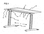
- Fig. 1 In addition to a table top 1 and a support frame 2, the desk shown has two table legs 3.
- the table legs are telescopic and can therefore be changed in length and are connected to the support frame.
- the table legs contain, for example, an electric motor and a threaded rod for automatic length change. Via a control device (not shown), when a switch (not shown) is operated by an operator, the electric motors are operated, the threaded rod rotates and the table legs are telescopically extended or shortened depending on the direction of rotation.
- the control device stops the electric motors when the operator releases the switch, actuates the switch again or another switch, or when a maximum or minimum extended position of the table legs is reached. Since such a table top is designed to carry relatively high loads, such as several monitors or numerous books / files, the mechanics and the electric motors are designed to be correspondingly powerful. This leads to the fact that relatively high forces act during an automatic height adjustment of the table top. Other mechanisms can be used as the motion drive, such as a differently realized electrically driven gear or a hydraulic or pneumatic mechanism. In the context of the invention, devices such as projectors, screens or the like that can be automatically retracted into the table are also considered as movable parts of furniture.
- collision detection devices are used that detect a collision of the table top with an obstacle via one or more sensors and report it to the control device, which then stops the operation of the electric motors.
- Piezo elements are not ideal for use in such articles.
- relatively complex electronics are necessary in order to first amplify the generated signals and then read them out.
- those in the EP 1 460 914 B1 Piezo sensors described not for measurements of a collision when starting the movement since an absolute measurement of the load cannot be measured. Due to the physical properties of the piezo element, a charge shift occurs during deformation. This generates a signal. As soon as the deformation stops, the signal will also stop. However, due to the connected electronics and the physical properties, charges flow away in this static state. When measuring again, incorrect measurements may occur, which can impair the reliability of the collision protection. At least no permanent, static loads can be recorded in this way.
- the WO 2011/083019 A1 further discloses a device for detecting collisions by means of a strain gauge.
- strain gauges usually first have to be applied to additional components, such as steel plates, which convert the acting force into an expanding deformation, which, in addition to the additional costs, is also associated with greater structural effort.
- a furniture column also includes those structures that are attached to cabinets and / or the hinges of which are to be provided in order to enable these components to be adjusted automatically. The same applies, for example, to armchairs or components of beds or bed frames.
- a piece of furniture can have at least one automatically or motorized movable part which is adapted to be moved non-manually relative to the rest of the piece of furniture.
- a piece of furniture has a device for detecting collisions with obstacles, as well as an automatic propulsion mechanism which moves the movable part, and a control device which controls the automatic propulsion mechanism.
- the piece of furniture also contains at least one sensor which can detect a collision during the movement of the movable part with an obstacle and transmit it to the controller.
- a force-sensitive sensor more precisely a drucckraftskeen sensor (for example, a so-called. "Force sensing resistor” short FSR ® from Interlink Electronics, Inc.), is applied directly to the compressive force. While the force-sensitive sensor is usually designed as a resistor, it is also conceivable that this sensor detects the change in a capacitance, inductance, magnetic properties or other physical quantities.
- An FSR used in the invention is characterized by a multi-layer, in particular two-layer structure. These are polymer films that change the electrical resistance of the FSR depending on the mutual contact area. In general, a larger contact area, which is usually associated with a greater pressure acting on the FSR, results in a lower resistance of the FSR.
- a first layer has conductive strip conductors therein, which can be connected to different electrodes. The conductor tracks are arranged at a distance from one another, for example, interlocking in a comb shape.
- a second layer of the FSR has a matrix of conductive and non-conductive components (a semiconducting paste). In an unloaded state of the FSR, the second conductor layer is insulated, for example at a distance, from the first layer.
- the distance between the layers is reduced or the contact between the layers is increased.
- the semiconducting paste of the second layer is pressed between the conductor tracks of the first layer and forms a conductive connection between the conductor tracks. This will reduce the resistance of the FSR.
- a resistance of the FSR between 10 - 100 k ⁇ can be achieved.
- the conductivity of the force-sensitive sensor is proportional to the pressure that is exerted on the force-sensitive sensor. It is also possible for only one conductor track to be provided on the first layer, the conductive paste of the second layer being connected to an electrode in this case. Depending on the planned use of the FSR, more than two conductor tracks can also be provided.
- the resistance as a variable to be recorded here is measured by connected electronics.
- both a collision during the movement of the movable part with an obstacle and a load on the furniture can be detected, be it due to the acceleration during the movement or a constant load from objects arranged on the furniture.
- the FSR can in particular be mounted axially above the driving motor in order to experience a direct force effect.
- the distance to the engine can be kept small in this way, which can bring structural advantages.
- an actuating component can be formed on the furniture on a side facing the FSR and in its effective range, which comes into effective contact with the FSR in the event of a collision and thus causes a change in conductivity in the FSR as described above.
- This actuating component can for example be made from a foam material, which in particular can also be an injectable foam material.
- the actuating component can also have an elastomer. This elastomer can also be provided so that it can be injected. The actuating component can contact the entire FSR or only a partial area of the FSR.
- the actuation component has an actuation projection which, for example, protrudes conically from the actuation component and thus has a contact area on the FSR that is predefined for different forces. It is also conceivable that the actuating projection has a step-shaped profile. Depending on the pressure acting on the FSR, different conductivities of the FSR are achieved, which can simplify reading out the load and identifying collisions or overloads. Of course, other shapes are also possible.
- At least one sensor is provided in the piece of furniture. At least one of the sensors provided in the piece of furniture can be arranged in such a way that, in the event of a collision, a pressure force acts on the FSR. It is also conceivable that a Sensor is arranged such that in the event of a collision of the movable part of the furniture, a tensile force is exerted on an FSR.
- At least one of the sensors or the one sensor can already be preloaded with a pressure force when the furniture is in a collision-free state, which is associated with a specific conductivity of the FSR, which can be detected as an initial value by the device for detecting collisions.
- An increase in the force as well as a decrease in the force can trigger a signal.
- a method for controlling the automatic movement of a movable part in a piece of furniture accordingly has the following steps: measuring a resistance of the force-sensitive sensor or the sensor signal, detecting a force, in particular a pressure force on the FSR in the sensor in the event of a collision of the piece of furniture an obstacle and / or detection of a load on the piece of furniture, be it in the event of a collision or in the static - i.e. immobile - state, sending a collision signal or an overload signal to the control device and stopping a movement in the case of an automatically controlled movement of the movable part the control device and / or triggering a warning signal in the event of overloading of the furniture, even in the static state.
- a sensor for use in a piece of furniture has an FSR as described.
- This sensor can accordingly be provided as a collision sensor and / or as a relative - that is to say during the movement - or an absolute - that is to say in the static state - weight sensor in the piece of furniture. In this way it can be achieved that the risk of overloading the motor, especially when starting up, is reduced.
- Fig. 1 shows, as an example of a piece of furniture, an automatically height-adjustable table with a table top 1 which has a front edge 11 and a rear edge 12.
- the table top 1 is fastened to a support frame 2, which consists of a front and a rear square support 21 and a right and a left support plate 22.
- the carrier plates 22 are each connected to table legs 3.
- a table leg consists of an inner table leg component 31, which is connected at its upper end to the support plate 22, and an outer table leg component 32, which are arranged one inside the other so that the table leg 3 can be telescopically changed in length.
- a foot component 33 is arranged perpendicular thereto.
- Inside the inner table leg component 31 are a motor, preferably an electric motor 5, and a spindle gear (not shown) with a threaded rod 6 (cf. Fig. 4 ) appropriate.
- the electric motors 5 of both table legs 3 are operated by a control device (not shown) and are adapted to close the threaded rod 6 rotate and so make an automatic change in length of the table legs 3. This will be described in more detail below.
- the control device is connected to a switch for selecting an upward movement and a downward movement of the table top 1.
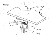
- a sensor 4 is located at the upper end of the hollow inner table leg component 31 in a position set back from the end of the inner table leg component facing the table top 1.
- the sensor 4 set back from the end of the inner table leg component 31 is shown here in an angular arrangement for a better overview.
- the sensor 4 is preferably arranged in the inner table leg component 31 such that an axis along the extension direction of the table leg 3 is perpendicular to the sensor surface of the sensor 4.
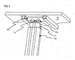
- the sensor 4 is located at the upper end of the inner table leg component 31, between the inner table leg component 31 and the table top 1.
- An additional plate 34 is also provided here between the sensor 4 and the table top 1.
- the additional plate 34 is used to make contact with the sensor 4 in the event of a collision of the movable part, in this case the table top 1, with an obstacle.
- the sensor 4 can also be fastened directly to the table top 1 or to the carrier plate 22, as long as a collision of the table top 1 with an obstacle leads to an action of force or a change in force on the sensor 4.
- a sensor 4 is attached in such a way that a collision during the upward movement of the table top 1 leads to a force acting on the sensor 4, since the threaded spindle moves the inner table leg component 31 and thus also the sensor 4 further in the direction of the colliding table top 1 pushes until a threshold value for the resistance of the sensor is reached, which causes the opening movement to stop.
- Another sensor 4 can be attached in such a way that it is already attached between the inner table leg component 31 and the table top 1 with a predetermined force being applied.
- Figure 4a shows a complete table leg 3 in a retracted state of the inner table leg component 31.
- the sensor 4 is arranged in a position axially above the electric motor 5, that is to say in a direction from the electric motor 5 towards the intermediate plate 34, within the inner table leg component 31.
- the electric motor 5 is also arranged in the interior of the inner table leg component 31 and in the region of an upper end of the inner table leg component 31.
- foot component 33 extends the threaded rod 6, which creates a coupling between the motor and thus the inner table leg component 31 and the outer table leg component 32.
- the threaded rod 6 has a shaft (not shown) that is shown in FIG Figure 4 is arranged within the component 6, as well as a shaft casing 61.
- the shaft is connected to the motor, while the shaft casing 61 of the threaded rod 6 is connected to the foot component 33 and / or to the outer table leg component 32 on a side facing the foot component 33.
- the shaft and the shaft cover 61 are threadedly engaged with each other (not shown).
- the inner table leg component 31 By coupling the electric motor 5 to the inner table leg component 31, the inner table leg component 31 experiences a relative movement to the outer table leg component 32.
- the table leg 3 is thus moved telescopically and the inner table leg component 31 is adjusted in height relative to the outer table leg component 32.
- the sensor 4 provided in this embodiment has a force-sensitive sensor (hereinafter also referred to as FSR according to the sensor that is preferably used) 41.
- the FSR 41 is arranged above the electric motor 5 in a sensor socket 40.
- the sensor socket 40 is designed in such a way that it is arranged in the inner table leg component 31 and above the electric motor 5.
- the FSR 41 has a measuring section and a coupling section.
- the measuring section is essentially a round surface to which the pressure for changing the resistance is to be applied.
- the coupling section also known as the tail, is a wired supply line that is used to couple the FSR 41 to the electronics connected behind it.
- FSR 41 does affect has its electrical conductivity, however, in the present invention, FSR with shapes other than those described can also be used. In particular, FSR with a rectangular shape or an irregular shape can be used. It is also conceivable that several FSR are used, or one FSR is designed in such a way that there are several contact surfaces with the pressure-exerting components.
- a damping element 42 is provided above the FSR 41, that is to say on a side of the FSR 41 facing away from the electric motor 5.
- the damping element 42 preferably has a sound or vibration damping material such as rubber or foam.
- the damping element 42 is arranged here within the effective range, but without contact, from the FSR 41. In alternative embodiments, the damping element 42 can also be in contact with the FSR 41, in particular with a defined preload.
- An actuating component 43 is again arranged above the damping element 42.
- the actuating component 43 can in particular be a plate made of steel and / or plastic. Both the damping element 42 and the actuating component 43 have a round design and can be introduced into the cavity of the inner table leg component 31.
- the actuating component 43 is provided in contact with the intermediate plate 34, the carrier plate 22 or directly with the table top 1 (not shown).
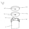
- the actuating component 43 has an actuating projection, here a single knob 45, as well as from Fig. 5 can be seen.
- this knob 45 is arranged around the center point of the actuating component 43.
- a plurality of actuating projections can also be provided on the actuating component.
- the knob 45 extends from the side of the actuating component 43 facing the FSR 41 in the direction of the FSR 41.
- the knob 45 is a conical projection.
- the nub can also have a stepped profile or any other shape.
- the damping element 42 has a bulge 44 into which the knob 45 extends in the assembled state of the sensor 4. It is also conceivable that the damping element 42 does not have a bulge and that the knob 45 can extend or press into the damping element 42 solely on the basis of its material properties. This applies in particular to very soft damping elements and / or very hard actuating components. If the actuating component is designed with a plurality of knobs, the damping element can analogously be designed with a plurality of bulges.
- the FSR 41 of the sensor 4 is arranged centered in the sensor socket 40.
- the damping element 42 and the actuating component 43 are arranged above the FSR in such a way that the knob 45 exerts a compressive force on the FSR 41 at least in the event of a collision of the table. This means that the FSR 41, the bulge 44 and the knob 45 are arranged one above the other in an axial direction within the effective range.
- Fig. 6 shows them off Fig. 5 described arrangement again from a perspective from obliquely below. It can be seen here that the bulge 44 enables the knob 45 to protrude in or through as far as the FSR 41.
- the damping means can also be designed with one or more holes corresponding to the knobs.
- the damping element 42 is made of a material that damps a transmission of vibrations from the movable part to the stationary part, but at the same time transfers a pressure load to the FSR in the event of a collision.
- the actuating element can be dispensed with.
- a column for a piece of furniture and a piece of furniture is described, with at least one automatically movable part 1, 2, 31, this part being adapted to be non-manually moved relative to the rest of the furniture.
- a device for detecting collisions of the automatically movable part with obstacles, an automatic propulsion mechanism 5, 6 which is adapted to move the movable portion, a control device which is adapted to control the automatic propulsion mechanism 5, 6, and at least one sensor 4 is provided which is adapted to detect a collision during the movement of the movable part 1, 2, 31 with an obstacle and to transmit it to the controller, the at least one sensor 4 having a force-sensitive sensor 41.
Landscapes
- Engineering & Computer Science (AREA)
- Power Engineering (AREA)
- Power-Operated Mechanisms For Wings (AREA)
- Tables And Desks Characterized By Structural Shape (AREA)
- Transmission Devices (AREA)
Description
- Die Erfindung betrifft eine Vorrichtung und ein Verfahren zur Erkennung von Kollisionen bei Möbeln, und betrifft insbesondere eine Vorrichtung und ein Verfahren zur Erkennung von Kollisionen von automatisch bewegbaren Anteilen von Möbeln mit Hindernissen.
- Aus dem Stand der Technik sind Möbel mit automatisch bewegbaren Anteilen wie beispielsweise Schreibtische mit einer automatisch höhenverstellbaren Tischplatte oder Schränke mit automatisch betätigten Türen bekannt. Hierbei sei mit "automatisch bewegbar" der Zustand bezeichnet, dass eine mögliche Bewegung von Anteilen von Möbeln in nicht-manueller Art angetrieben wird, beispielsweise durch einen Federmechanismus, einen hydraulischen oder pneumatischen Mechanismus oder ein motorbetriebenes Getriebe. Ein solcher, in
Fig. 1 gezeigter Schreibtisch weist neben einer Tischplatte 1 und einem Trägergerüst 2 zwei Tischbeine 3 auf. Die Tischbeine sind teleskopartig ausgebildet und damit in der Länge veränderbar und sind mit dem Trägergerüst verbunden. Die Tischbeine beinhalten beispielsweise einen Elektromotor und eine Gewindestange zur automatischen Längenveränderung. Über eine nicht gezeigte Steuervorrichtung werden bei Betätigung eines nicht gezeigten Schalters durch einen Bediener die Elektromotoren betrieben, die Gewindestange rotiert und die Tischbeine werden je nach Rotationsrichtung teleskopartig verlängert oder verkürzt. - Die Steuervorrichtung hält die Elektromotoren an, wenn der Bediener den Schalter loslässt, den Schalter erneut oder einen weiteren Schalter betätigt, oder wenn eine maximale oder minimale Ausfahrstellung der Tischbeine erreicht wird. Da eine solche Tischplatte darauf ausgelegt ist, relativ hohe Lasten zu tragen, wie mehrere Monitore oder zahlreiche Bücher/Akten, sind die Mechanik und die Elektromotoren entsprechend leistungsfähig ausgelegt. Dies führt dazu, dass bei einer automatischen Höhenverstellung der Tischplatte relativ hohe Kräfte wirken. Als Bewegungsantrieb sind andere Mechanismen verwendbar, wie ein anders realisiertes elektrisch angetriebenes Getriebe, oder ein hydraulischer oder pneumatischer Mechanismus. Im Rahmen der Erfindung werden auch Geräte, wie beispielsweise automatisch im Tisch versenkbare Projektoren, Bildschirme oder dergleichen als bewegbare Anteile von Möbeln betrachtet.
- Natürlich sind auch andere Möbel mit automatisch verstellbaren Bauteilen bekannt. Dies können Schränke mit bewegbaren Türen ebenso sein, wie höhenverstellbare Stühle oder Betten bzw. Bettkomponenten. Hier ist insbesondere auch an Bettelemente wie teilweise verstellbare Roste zu denken.
- Bei der Verstellung, nun am Beispiel einer Höhenverstellung einer Tischplatte, kann es zu Beschädigungen am Tisch und dritten Gegenständen oder gar zu Verletzungen von Personen führen, die sich über- oder unterhalb der Tischplatte befinden, wenn es bei der Höhenverstellung zu einer Kollision zwischen Tischplatte und dem Gegenstand kommt. Um dies zu verhindern, werden Kollisionserkennungsvorrichtungen eingesetzt, die eine Kollision der Tischplatte mit einem Hindernis über einen oder mehrere Sensoren erfassen und an die Steuervorrichtung melden, die daraufhin den Betrieb der Elektromotoren anhält.
- Aus
EP 1 460 914 B1 ist eine Vorrichtung mit verstellbaren Elementen bekannt, wobei in der Vorrichtung ein piezoelektrischer Sensor vorgesehen ist, der im Falle einer erfassten Kollision ein entsprechendes Steuersignal zum Stoppen oder Umkehren der Bewegung auslöst. - Piezoelemente sind jedoch nicht ideal für die Anwendung in derartigen Gegenständen. Zum einen ist eine relativ komplizierte Elektronik notwendig, um die erzeugten Signale zunächst zu verstärken und dann auszulesen. Zum anderen eignen sich die in der
EP 1 460 914 B1 beschriebenen Piezosensoren nicht für Messungen einer Kollision beim Starten der Bewegung, da eine absolute Messung der Belastung nicht gemessen werden kann. Aufgrund der physikalischen Eigenschaften des Piezoelements kommt es während einer Verformung zu einer Ladungsverschiebung. Diese erzeugt ein Signal. Sobald die Verformung stoppt, wird auch das Signal gestoppt. Aufgrund der angeschlossenen Elektronik und der physikalischen Eigenschaften fließen in diesem statischen Zustand jedoch trotzdem Ladungen ab. So kann es bei einem erneuten Messen ggf. zu Fehlmessungen kommen, die die Zuverlässigkeit des Kollisionsschutzes beeinträchtigen können. Zumindest können auf diese Weise keine permanenten, statischen Belastungen erfasst werden. - Die
WO 2011/083019 A1 offenbart ferner eine Vorrichtung zum Erkennen von Kollisionen mittels eines Dehnungsmessstreifens. Diese bringen jedoch den Nachteil mit sich, dass Dehnungsmessstreifen für gewöhnlich erst auf zusätzliche Bauteile, wie beispielsweise Stahlplatten, die die einwirkende Kraft in eine dehnende Verformung konvertieren, aufgebracht werden müssen, was neben den Mehrkosten auch mit einem höheren baulichen Aufwand verbunden ist. - Es ist daher Aufgabe der Erfindung, ein Möbelstück mit einem Kollisionsschutz zur Verfügung zu stellen, der zumindest einen Nachteil gegenüber dem Stand der Technik vermeidet und der eine zuverlässige Kollisionsmessung ermöglicht.
- Diese Aufgabe wird mit einer Möbelsäule gemäß Anspruch 1 bzw. einem Möbel nach Anspruch 14 gelöst. Vorteilhafte Weiterbildungen sind Gegenstand der Unteransprüche.
- Für die folgenden Erklärungen ist zu beachten, dass sich die Ausführungen stets auch auf eine Möbelsäule beziehen, auch wenn lediglich von einem Möbel die Rede ist. Eine Möbelsäule, wie sie von dem Schutzumfang hier umfasst sein soll, beinhaltet auch diejenigen Strukturen, die beispielsweise an Schränken und/oder deren Scharniere vorzusehen sind, um eine automatische Verstellung dieser Komponenten zu ermöglichen. Selbiges gilt beispielsweise für Sessel oder Komponenten von Betten oder Bettgestellen.
- Ein Möbelstück kann mindestens einen automatisch bzw. motorisch bewegbaren Anteil aufweisen, der daran angepasst ist, relativ zu dem restlichen Möbelstück nicht-manuell bewegt zu werden. Ein derartiges Möbelstück weist eine Vorrichtung zur Erkennung von Kollisionen mit Hindernissen auf, sowie einen automatischen Vortriebsmechanismus, der den bewegbaren Anteil bewegt, und eine Steuereinrichtung, die den automatischen Vortriebsmechanismus steuert. Weiterhin ist mindestens ein Sensor in dem Möbel enthalten, der eine Kollision bei der Bewegung des bewegbaren Anteils mit einem Hindernis erfassen und an die Steuerung übermitteln kann. Erfindungsgemäß handelt es sich um einen kraftempfindlichen Sensor, genauer um einen drucckraftempfindlichen Sensor (beispielsweise ein sog. "force sensing resistor" kurz FSR® der Firma Interlink Electronics, Inc.), auf den eine Druckkraft direkt ausgeübt wird. Während der Kraftempfindliche Sensor üblicherweise als ein Widerstand ausgebildet ist, ist es jedoch auch denkbar, dass dieser Sensor die Änderung einer Kapazität, Induktivität, magnetischer Eigenschaften oder andere physikalischen Größen erfasst.
- Ein in der Erfindung verwendeter FSR zeichnet sich durch einen mehrlagigen, insbesondere zweilagigen Aufbau aus. Es handelt sich dabei um Polymerfilme, die, abhängig von der gegenseitigen Kontaktfläche den elektrischen Widerstand des FSR verändern. Generell gilt, dass eine größere Berührungsfläche, die in der Regel mit einem größeren auf den FSR wirkenden Druck einhergeht, einen geringeren Widerstand des FSR zur Folge hat. Darin weist eine erste Schicht leitfähige Leiterbahnen auf, die mit verschiedenen Elektroden verbunden sein können. Die Leiterbahnen sind dabei beabstandet voneinander angeordnet, beispielsweise kammförmig ineinander greifend. Eine zweite Schicht des FSR weist eine Matrix aus leitfähigen und nicht-leitfähigen Komponenten (eine halbleitende Paste) auf. Die zweite Leiterschicht ist in einem unbelasteten Zustand des FSR isoliert, beispielsweise beabstandet, von der ersten Schicht angeordnet. Durch Zusammendrücken des FSR wird der Abstand der Schichten zueinander verringert bzw. der Kontakt der Schichten miteinander erhöht. Abhängig von dem ausgeübten Druck bzw. der ausgeübten Kraft, wird die halbleitende Paste der zweiten Schicht zwischen die Leiterbahnen der ersten Schicht gepresst und bildet eine leitfähige Verbindung zwischen den Leiterbahnen. Dadurch verringert sich der Widerstand des FSR. So kann beispielsweise ein Widerstand des FSR zwischen 10 - 100 kΩ erreicht werden. Die Leitfähigkeit des Kraftempfindlichen Sensors verläuft proportional zu der Drucckraft, die auf den Kraftempfindlichen Sensor ausgeübt wird. Es kann auch nur eine Leiterbahn auf der ersten Schicht vorgesehen sein, wobei die leitfähige Paste der zweiten Schicht in diesem Fall mit einer Elektrode verbunden ist. Abhängig von dem geplanten Einsatz des FSR können auch mehr als zwei Leiterbahnen vorgesehen sein. Der Widerstand als eine hier zu erfassende Größe wird dabei von einer angeschlossenen Elektronik gemessen.
- Durch die Verwendung eines derartigen FSR kann sowohl eine Kollision bei der Bewegung des bewegbaren Anteils mit einem Hindernis erfasst werden, als auch eine Belastung des Möbels, sei es durch die Beschleunigung bei der Bewegung oder einer ständigen Belastung durch auf dem Möbel angeordnete Gegenstände.
- Dies ist möglich durch den speziellen Aufbau eines FSR mit zwei Schichten wie oben beschrieben, wobei eine der Schichten eine leitfähige Beschichtung aufweist, die, wenn sie beispielsweise durch eine Drucckraft in Kontakt mit der zweiten, davon geringfügig beabstandeten Schicht gebracht wird, eine Veränderung der Leitfähigkeit erfährt. Die Leitfähigkeit bzw. der Widerstand korreliert dabei mit dem auf den FSR ausgeübten Druck und somit auch mit der wirkenden Kraft.
- Der FSR kann insbesondere axial über dem antreibenden Motor angebracht sein, um eine direkte Kraftwirkung zu erfahren. Zudem kann auf diese Weise der Abstand zum Motor gering gehalten werden, was bauliche Vorteile mit sich bringen kann.
- Weiterhin kann an dem Möbel an einer dem FSR zugewandten Seiten und in dessen Wirkreichweite ein Betätigungsbauteil ausgebildet sein, das bei einer Kollision in Wirkkontakt mit dem FSR gerät und somit wie oben beschrieben eine Leitfähigkeitsänderung in dem FSR bewirkt.
- Dieses Betätigungsbauteil kann beispielsweise aus einem Schaumstoffmaterial hergestellt sein, das insbesondere auch ein spritzfähiges Schaumstoffmaterial sein kann. Alternativ oder zusätzlich kann das Betätigungsbauteil auch ein Elastomer aufweisen. Dieses Elastomer kann ebenso spritzbar vorgesehen sein. Das Betätigungsbauteil kann dabei den gesamten FSR oder nur einen Teilbereich des FSR kontaktieren.
- Dabei ist insbesondere vorstellbar, dass das Betätigungsbauteil einen Betätigungsvorsprung aufweist, der beispielsweise konisch von dem Betätigungsbauteil hervorragt und so einen für verschiedene Krafteinwirkungen vordefinierten Berührungsbereich auf dem FSR aufweist. Auch ist denkbar, dass der Betätigungsvorsprung ein stufenförmiges Profil aufweist. Abhängig von dem auf den FSR wirkenden Druck werden so verschiedene Leitfähigkeiten des FSR erreicht, was ein Auslesen der Belastung und ein Identifizieren von Kollisionen oder Überlastungen vereinfachen kann. Natürlich sind auch andere Formen möglich.
- Dabei ist zu beachten, dass in dem Möbel wenigstens ein Sensor, möglicherweise jedoch eine Mehrzahl von Sensoren vorgesehen ist. Wenigstens einer der in dem Möbel vorgesehenen Sensoren kann dabei derart angeordnet sein, dass im Falle einer Kollision eine Drucckraft auf den FSR wirkt. Es ist auch denkbar, dass ein Sensor derart angeordnet ist, dass im Falle einer Kollision des bewegbaren Anteils des Möbels eine Zugkraft auf einen FSR ausgeübt wird.
- In dem ersten, oben geschilderten Fall ist eine Kollision beispielsweise einer Tischoberfläche beim Auffahren des Tisches mit einem Hindernis wie einem offenen Fenster oder einem Regal, vorstellbar. Hier würde ein weiteres Auffahren der Säule gegen den Widerstand der kollidierten Platte eine Druckkraft auf den FSR ausüben, was ab einem bestimmten, vordefinierten Schwellenwert zu einem entsprechenden Signal an die Steuereinrichtung führt.
- In dem anderen Fall ist es denkbar, dass beim Herabfahren des Tisches die Tischplatte an unter dem Tisch befindliche Gegenstände anstößt und somit der bewegbare Anteil des Möbels relativ zu dessen Bewegungsrichtung ins Stocken gerät. Dadurch wird folglich eine Zugkraft aufgrund der Relativbewegung zwischen verschiedenen Komponenten des bewegbaren Anteils, beispielsweise einer Tischplatte und einem mit dem Motor verbundenen Bewegungselement verursacht. Wenn der FSR mit beiden Komponenten gekoppelt ist, wird hier die Zugkraft auch auf den FSR ausgeübt und es kann ein Signal ausgelöst werden.
- Auch kann zur besseren Erfassung wenigstens einer der Sensoren beziehungsweise der eine Sensor bereits in einem kollisionsfreien Zustand des Möbels mit einer Druckkraft vorbeaufschlagt sein, was mit einer spezifischen Leitfähigkeit des FSR einhergeht, die von der Vorrichtung zur Erkennung von Kollisionen als Ausgangswert erfasst werden kann. So kann eine Erhöhung der Kraft wie auch eine Verringerung der Kraft zu einer Signalauslösung führen.
- Ein Verfahren zur Steuerung der automatischen Bewegung eines bewegbaren Anteils in einem Möbel weist entsprechend die Schritte auf: Ausmessen eines Widerstands des Kraftempfindlichen Sensors bzw. des Sensorsignals, Erfassen einer Kraft, insbesondere einer Druckkraft auf den FSR in dem Sensor im Falle einer Kollision des Möbels mit einem Hindernis und/oder Erfassen einer Belastung des Möbelstücks, sei es im Falle einer Kollision oder im statischen - also unbewegten - Zustand, Senden eines Kollisionssignals bzw. eines Überlastungssignals an die Steuereinrichtung und Stoppen einer Bewegung im Falle einer automatisch gesteuerten Bewegung des bewegbaren Anteils durch die Steuereinrichtung und/oder Auslösen eines Warnsignals im Falle einer Überladung des Möbels, auch im statischen Zustand. Zudem ist in weiteren Ausführungsformen auch denkbar, dass bei dem Erfassen einer Überladung des Möbelstücks eine Bewegung nicht ausgelöst wird, z.B. weil ein Steuersignal zum Verstellen des bewegbaren Anteils gar nicht erst ausgegeben wird. So kann eine Beschädigung des Motors durch Überlastung vermieden werden.
- Ein Sensor zur Verwendung in einem Möbel weist dabei einen FSR wie beschrieben auf. Dieser Sensor kann entsprechend als Kollisionssensor und/oder als ein relativer - also während der Bewegung - oder ein absoluter - also im statischen Zustand - Gewichtssensor in dem Möbel vorgesehen sein. So kann erreicht werden, dass die Gefahr einer Überlastung des Motors, insbesondere beim Anfahren verringert wird.
- Einzelheiten, weitere Vorteile und Weiterentwicklungen der Erfindung werden anhand von Ausführungsbeispielen unter Bezugnahme auf die Zeichnungen näher erläutert. Dabei zeigt:
- Fig. 1
- eine Schrägansicht eines automatisch höhenverstellbaren Tisches wie aus dem Stand der Technik bekannt;
- Fig. 2
- eine Ausschnittsansicht mit einer Sensoranbringungsstelle innerhalb eines Tischbeins gemäß einer Ausführungsform der Erfindung;
- Fig. 3
- eine Ausschnittsansicht mit einer Sensoranbringungsstelle außerhalb eines Tischbeins gemäß einer weiteren Ausführungsform der Erfindung;
- Fig. 4
- eine bewegbare Säule mit einem erfindungsgemäßen Sensor gemäß einer Ausführungsform der Erfindung a) als Gesamtansicht der Säule, b) in Detailansicht eines Teilbereichs der Säule;
- Fig. 5
- eine perspektivische Explosionsdarstellung eines erfindungsgemäßen Sensors in einer bewegbaren Säule von schräg oben;
- Fig. 6
- eine perspektivische Explosionsdarstellung eines erfindungsgemäßen Sensors in einer bewegbaren Säule von schräg unten.
-
Fig. 1 zeigt als Beispiel für ein Möbelstück einen automatisch höhenverstellbaren Tisch mit einer Tischplatte 1, die eine Vorderkante 11 und eine Rückkante 12 aufweist. Die Tischplatte 1 ist auf einem Trägergerüst 2 befestigt, das aus einem vorderen und einem hinteren Vierkantträger 21 und einer rechten und einer linken Trägerplatte 22 besteht. Die Trägerplatten 22 sind jeweils mit Tischbeinen 3 verbunden. Ein Tischbein besteht aus einem inneren Tischbeinbauteil 31, das an seinem oberen Ende mit der Trägerplatte 22 verbunden ist, und einem äußeren Tischbeinbauteil 32, die so ineinander angeordnet sind, dass das Tischbein 3 teleskopartig in der Länge veränderbar ist. Am unteren Ende des äußeren Bauteils 32 ist senkrecht dazu ein Fußbauteil 33 angeordnet. Innerhalb des inneren Tischbeinbauteils 31 sind ein Motor, vorzugsweise ein Elektromotor 5, und ein nicht gezeigtes Spindelgetriebe mit Gewindestange 6 (vgl.Fig. 4 ) angebracht. - Die Elektromotoren 5 beider Tischbeine 3 werden durch eine nicht gezeigte Steuervorrichtung betrieben und sind daran angepasst, die Gewindestange 6 zu rotieren und so eine automatische Längenveränderung der Tischbeine 3 vorzunehmen. Dies wird im Folgenden noch detaillierter beschrieben werden. Die Steuervorrichtung ist mit jeweils einem Schalter zur Anwahl einer Aufwärtsbewegung und einer Abwärtsbewegung der Tischplatte 1 verbunden.
- Wie in
Fig. 2 gezeigt ist, befindet sich in der hier gezeigten Ausführungsform ein Sensor 4 an dem oberen Ende des hohlen inneren Tischbeinbauteils 31 in einer von dem der Tischplatte 1 zugewandten Ende des inneren Tischbeinbauteils zurückgesetzten Position. Der von dem Ende des inneren Tischbeinbauteils 31 zurückgesetzte Sensor 4 ist hier zur besseren Übersicht in einer winkeligen Anordnung dargestellt. Vorzugsweise ist der Sensor 4 in dieser wie auch in den folgenden beschriebenen Ausführungsformen derart in dem inneren Tischbeinbauteil 31 angeordnet, dass eine Achse entlang der Erstreckungsrichtung des Tischbeins 3 senkrecht zu der Sensorfläche des Sensors 4 steht. - In einer anderen Ausführungsform, wie sie in
Fig. 3 gezeigt ist, befindet sich der Sensor 4 an dem oberen Ende des inneren Tischbeinbauteils 31, zwischen dem inneren Tischbeinbauteil 31 und der Tischplatte 1. Dabei ist zwischen dem Sensor 4 und der Tischplatte 1 hier noch eine Zusatzplatte 34 vorgesehen. Die Zusatzplatte 34 dient der Kontaktierung mit dem Sensor 4 im Falle einer Kollision des bewegbaren Anteils, hier also der Tischplatte 1, mit einem Hindernis. Der Sensor 4 kann auch direkt an der Tischplatte 1 oder an der Trägerplatte 22 befestigt sein, solange eine Kollision der Tischplatte 1 mit einem Hindernis zu einer Krafteinwirkung bzw. Kraftänderung auf den Sensor 4 führt. - Insbesondere ist auch vorstellbar, dass ein Sensor 4 derart angebracht ist, dass eine Kollision bei der Auffahrbewegung der Tischplatte 1 zu einer Krafteinwirkung auf den Sensor 4 führt, da die Gewindespindel das innere Tischbeinbauteil 31 und somit auch den Sensor 4 weiter in Richtung der kollidierenden Tischplatte 1 drängt, bis ein Schwellenwert des Widerstands des Sensors erreicht wird, der ein Stoppen der Auffahrbewegung bewirkt. Ein weiterer Sensor 4 kann derart angebracht sein, dass er bereits mit einer vorbestimmten Krafteinwirkung zwischen dem inneren Tischbeinbauteil 31 und der Tischplatte 1 angebracht ist. Im Falle einer Kollision beim Herabfahren der Tischplatte 1 mit einem Hindernis, dass sich entsprechend unterhalb der Tischplatte befindet, würde der Motor bzw. die Gewindespindel das innere Tischbeinbauteil 31 weiter von der Tischplatte 1 ziehen, so dass eine Zugkraft auf den Sensor 4 wirkt, die der vorbestimmten Druckkraft entgegenwirkt und wiederum zu einer Widerstandsänderung des Sensors 4 führt.
-
Fig. 4a zeigt ein komplettes Tischbein 3 in einem eingefahrenen Zustand des inneren Tischbeinbauteils 31. Wie insbesondere aus der Detailansicht ausFig. 4 b) hervorgeht, ist der Sensor 4 in einer Position axial oberhalb des Elektromotors 5, also in einer Richtung vom Elektromotor 5 hin zu der Zwischenplatte 34, innerhalb des inneren Tischbeinbauteils 31 angeordnet. Der Elektromotor 5 ist dabei ebenfalls im Inneren des inneren Tischbeinbauteils 31 und im Bereich eines oberen Endes des inneren Tischbeinbauteils 31 angeordnet. In einer Richtung von dem Elektromotor 5 zu dem inFig. 4 nicht gezeigten Fußbauteil 33 erstreckt sich die Gewindestange 6, die eine Kopplung zwischen dem Motor und somit dem inneren Tischbeinbauteil 31 sowie dem äußeren Tischbeinbauteil 32 schafft. - Die Gewindestange 6 weist eine Welle (nicht gezeigt), die in
Figur 4 innerhalb des Bauteils 6 angeordnet ist, sowie eine Wellenumhüllung 61 auf. Die Welle ist mit dem Motor verbunden, während die Wellenumhüllung 61 der Gewindestande 6 an einer dem Fußbauteil 33 zugewandten Seite mit dem Fußbauteil 33 und/oder mit dem äußeren Tischbeinbauteil 32 verbunden ist. Die Welle und die Wellenumhüllung 61 sind miteinander über ein Gewinde in Eingriff (nicht gezeigt). Eine Rotation der Welle bewirkt dann durch die Kopplung der Gewindestange 6 bzw, der Wellenumhüllung 61 mit den Tischbeinbauteilen 31, 32eine Verschiebung des Motors in vertikaler, axialer Richtung, abhängig von der Drehrichtung - der Welle in Richtung des Fußbauteils 33 oder in eine dem Fußbauteil 33 abgewandte Richtung. Durch die Kopplung des Elektromotors 5 mit dem inneren Tischbeinbauteil 31 erfährt das innere Tischbeinbauteil 31 eine Relativbewegung zu dem äußeren Tischbeinbauteil 32. Das Tischbein 3 wird somit teleskopartig verfahren und es wird eine Höhenverstellung des inneren Tischbeinbauteils 31 relativ zu dem äußeren Tischbeinbauteil 32 hergestellt. - Es ist natürlich auch denkbar, dass andere Arten der Kopplung des inneren Tischbeinbauteils 31 mit dem äußeren Tischbeinbauteil 32 verwendet werden. So ist auch vorstellbar, dass Seilzüge eingesetzt werden oder Koppelelemente verwendet werden, die eine entsprechende Kopplung der relativ zueinander bewegbaren Elemente herstellen. Zudem ist denkbar, dass der Motor an einer anderen Position, beispielsweise im Bereich des Fußbauteils angeordnet ist, oder dass mehr als ein Motor und/oder mehr als zwei Tischbeinbauteile verwendet werden.
- Wie weiter in
Fig. 4 zu sehen ist, weist der in dieser Ausführungsform vorgesehene Sensor 4 einen Kraftempfindlichen Sensor (im Folgenden auch gemäß dem bevorzugt verwendeten Sensor als FSR bezeichnet) 41 auf. Der FSR 41 ist oberhalb des Elektromotors 5 in einer Sensorfassung 40 angeordnet. Die Sensorfassung 40 ist dabei so ausgebildet, dass sie in dem inneren Tischbeinbauteil 31 und oberhalb des Elektromotors 5 angeordnet ist. Der FSR 41 hat einen Messabschnitt und einen Kopplungsabschnitt. Der Messabschnitt ist vorliegend im Wesentlichen eine runde Fläche, auf die der Druck zum Ändern des Widerstands aufzubringen ist. Der Kopplungsabschnitt, auch als Schwanz bezeichnet, ist eine verdrahtete Zuleitung, die zur Kopplung des FSR 41 an die dahintergeschaltete Elektronik dient. Es ist zu beachten, dass die Form des FSR 41 zwar Einfluss auf seine elektrische Leitfähigkeit hat, in der vorliegenden Erfindung jedoch auch FSR mit anderen Formen als beschrieben eingesetzt werden können. Insbesondere können FSR mit rechteckiger Form oder unregelmäßiger Form eingesetzt werden. Auch ist es denkbar, dass mehrere FSR eingesetzt werden, oder ein FSR derart ausgebildet ist, dass es mehrere Kontaktflächen mit den Druckausübenden Bauteilen gibt. - Oberhalb des FSR 41, also auf einer dem Elektromotor 5 abgewandten Seite des FSR 41, ist ein Dämpfungselement 42 vorgesehen. Das Dämpfungselement 42 weist vorzugsweise einen Schall- bzw. Vibrationsdämpfenden Werkstoff, wie beispielsweise Gummi oder Schaumstoff, auf. Das Dämpfungselement 42 ist hier in Wirkreichweite, aber kontaktfrei von dem FSR 41 angeordnet. In alternativen Ausführungsformen kann das Dämpfungselement 42 auch im Kontakt, insbesondere mit einer definierten Vorbelastung, mit dem FSR 41 ausgebildet sein.
- Wiederum oberhalb des Dämpfungselements 42 ist ein Betätigungsbauteil 43 angeordnet. Das Betätigungsbauteil 43 kann insbesondere eine Platte sein, die aus Stahl und/oder Kunststoff besteht. Sowohl das Dämpfungselement 42 als auch das Betätigungsbauteil 43 weisen eine runde Bauweise auf und lassen sich in den Hohlraum des inneren Tischbeinbauteils 31 einbringen. Das Betätigungsbauteil 43 ist dabei in Kontakt mit der Zwischenplatte 34, der Trägerplatte 22 oder direkt mit der Tischplatte 1 vorgesehen (nicht gezeigt).
- In einer bevorzugten Ausführungsform der Erfindung weist das Betätigungsbauteil 43 einen Betätigungsvorsprung, hier eine einzelne Noppe 45, auf, wie auch aus
Fig. 5 ersichtlich ist. In der gezeigten Ausführungsform ist diese Noppe 45 um den Mittelpunkt des Betätigungsbauteils 43 angeordnet. In alternativen Ausführungsformen kann auch eine Mehrzahl von Betätigungsvorsprüngen an dem Betätigungsbauteil vorgesehen sein. Die Noppe 45 erstreckt sich von der dem FSR 41 zugewandten Seite des Betätigungsbauteils 43 in Richtung zu dem FSR 41. In der gezeigten Ausführung ist die Noppe 45 ein konischer Vorsprung. In anderen Ausführungen kann die Noppe auch ein Stufenprofil oder eine andere, beliebige Form haben. - Korrespondierend und vorzugsweise formschlüssig mit der Noppe 45 des Betätigungsbauteils 43 weist das Dämpfungselement 42 eine Ausbuchtung 44 auf, in die sich die Noppe 45 in zusammengesetztem Zustand des Sensors 4 erstreckt. Es ist auch denkbar, dass das Dämpfungselement 42 keine Ausbuchtung aufweist und sich die Noppe 45 allein aufgrund ihrer Materialeigenschaften in das Dämpfungselement 42 erstrecken bzw. eindrücken kann. Dies gilt insbesondere für sehr weiche Dämpfungselemente und/oder sehr harte Betätigungsbauteile. Wenn das Betätigungsbauteil mit einer Mehrzahl von Noppen ausgebildet ist, so kann das Dämpfungselement analog mit einer Mehrzahl von Ausbuchtungen ausgebildet werden.
- Der FSR 41 des Sensors 4 ist zentriert in der Sensorfassung 40 angeordnet. Dabei werden das Dämpfungselement 42 und das Betätigungsbauteil 43 derart über dem FSR angeordnet, dass die Noppe 45 zumindest im Falle einer Kollision des Tisches eine Druckkraft auf den FSR 41 ausübt. Das bedeutet, der FSR 41, die Ausbuchtung 44 und die Noppe 45 sind in einer axialen Richtung in Wirkreichweite übereinander angeordnet.
-
Fig. 6 zeigt die ausFig. 5 beschriebene Anordnung erneut aus einer Perspektive von schräg unten. Hier ist zu erkennen, dass die Ausbuchtung 44 ein Hinein- bzw. Hindurchragen der Noppe 45 bis hin zu dem FSR 41 ermöglicht. Das Dämpfungsmittel kann auch mit einem oder mehreren zu den Noppen korrespondierenden Löchern ausgebildet sein. - Es ist alternativ auch denkbar, dass das Dämpfungselement 42 aus einem Material hergestellt ist, dass eine Schwingungsübertragung von dem bewegbaren Anteil auf den feststehenden Anteil dämpft, aber gleichzeitig im Falle einer Kollision eine Druckbelastung auf den FSR überträgt. In diesem Fall kann auf das Betätigungselement verzichtet werden.
- Zusammenfassend ist eine Säule für ein Möbelstück und ein Möbelstück beschrieben, mit mindestens einem automatisch bewegbaren Anteil 1, 2, 31, wobei dieser Anteil daran angepasst ist, relativ zu dem restlichen Möbel nicht-manuell bewegt zu werden. Dabei ist eine Vorrichtung zur Erkennung von Kollisionen des automatisch bewegbaren Anteils mit Hindernissen, ein automatischer Vortriebsmechanismus 5, 6, der daran angepasst ist, den bewegbaren Anteil zu bewegen, eine Steuereinrichtung, die daran angepasst ist, den automatischen Vortriebsmechanismus 5, 6 zu steuern, und mindestens ein Sensor 4 vorgesehen, der daran angepasst ist, eine Kollision bei der Bewegung des bewegbaren Anteils 1, 2, 31 mit einem Hindernis zu erfassen und an die Steuerung zu übermitteln wobei der mindestens eine Sensor 4 einen Kraftempfindlichen Sensor 41 aufweist.
Claims (14)
- Möbelsäule mit mindestens einem motorisch bewegbaren Anteil (1, 2, 31), der relativ zu dem restlichen Möbel bewegbar ist, aufweisend: eine Vorrichtung zur Erkennung von Kollisionen des bewegbaren Anteils (1, 2, 31) mit Hindernissen, einen automatischen Vortriebsmechanismus, der daran angepasst ist, den bewegbaren Anteil zu bewegen, eine Steuereinrichtung, die daran angepasst ist, den automatischen Vortriebsmechanismus zu steuern, und mindestens einen Sensor (4), der daran angepasst ist, eine Kollision bei der Bewegung des bewegbaren Anteils (1, 2, 31) mit einem Hindernis zu erfassen und an die Steuerung zu übermitteln, dadurch gekennzeichnet dass der mindestens eine Sensor einen Kraftempfindlichen Sensor (41) aufweist, wobei ein Steuersignal abhängig von einem Leitfähigkeitswert des Kraftempfindlichen Sensors erzeugbar ist, wobei
der Kraftempfindliche Sensor zumindest eine Leiterschicht und eine Matrix aus leitendem und nicht leitendem Material aufweist. - Möbelsäule nach Anspruch 1, wobei der Kraftempfindliche Sensor derart ausgebildet ist, dass sich die Leitfähigkeit des Kraftempfindlichen Sensors proportional zu einer auf den Kraftempfindlichen Sensor wirkenden Druckkraft verhält.
- Möbelsäule nach Anspruch 1, wobei der Kraftempfindliche Sensor axial über dem Motor (5) angeordnet ist.
- Möbelsäule nach einem der vorhergehenden Ansprüche, wobei an dem Möbel ein Betätigungsbauteil in Wirkreichweite mit dem Kraftempfindlichen Sensor vorgesehen ist.
- Möbelsäule nach Anspruch 4, wobei das Betätigungsbauteil (43) ein Schaumstoffmaterial und/oder ein Elastomer aufweist.
- Möbelsäule nach Anspruch 5, wobei das Schaumstoffmaterial und/oder das Elastomer spritzbar ist.
- Möbelsäule nach einem der Ansprüche 4 bis 6, wobei das Betätigungsbauteil (43) einen Betätigungsvorsprung (45) aufweist.
- Möbelsäule gemäß Anspruch 7, wobei der Betätigungsvorsprung (45) eine konische Form aufweist.
- Möbelsäule nach einem der vorhergehenden Ansprüche, wobei mindestens ein Sensor (4) derart angeordnet ist, dass im Falle einer Kollision eine Druckkraft auf den Kraftempfindlichen Sensor (41) wirkt.
- Möbelsäule nach einem der vorhergehenden Ansprüche, wobei mindestens ein Sensor (4) derart angeordnet ist, dass im Falle einer Kollision eine Zugkraft auf den Kraftempfindlichen Sensor (41) wirkt.
- Möbelsäule nach einem der vorhergehenden Ansprüche, wobei mindestens einer der Sensoren (4) in einem kollisionsfreien Zustand mit einer Druckkraft vorbeaufschlagt ist.
- Verfahren zur Steuerung der automatischen Bewegung des bewegbaren Anteils in einer Möbelsäule gemäß einem der vorhergehenden Ansprüche, das die Schritte aufweist:- Ausmessen des Widerstandes des Kraftempfindlichen Sensors;- Erfassen einer Druckkraft auf den Kraftempfindlichen Sensor in dem Sensor im Fälle einer Kollision des Möbels mit einem Hindernis;- Senden eines Kollisionssignals an die Steuereinrichtung;- Stoppen der Bewegung des bewegbaren Anteils durch die Steuereinrichtung.
- Verfahren zur Steuerung der automatischen Bewegung des bewegbaren Anteils gemäß Anspruch 12, das den Schritt aufweist:- Umkehren der Bewegungsrichtung des bewegbaren Anteils für eine bestimmte Zeit und/oder Wegstrecke nach dem Erfassen einer Kollision.
- Möbel mit mindestens einer Möbelsäule gemäß einem der Ansprüche 1 bis 11.
Priority Applications (4)
| Application Number | Priority Date | Filing Date | Title |
|---|---|---|---|
| EP11185649.8A EP2583586B2 (de) | 2011-10-18 | 2011-10-18 | Vorrichtung zur Erfassung von Kollisionen und entsprechendes Verfahren |
| DK11185649.8T DK2583586T4 (da) | 2011-10-18 | 2011-10-18 | Indretning til registrering af kollisioner og tilsvarende fremgangsmåde |
| PL11185649T PL2583586T5 (pl) | 2011-10-18 | 2011-10-18 | Urządzenie do wykrywania kolizji i odpowiedni sposób |
| US13/653,429 US9236817B2 (en) | 2011-10-18 | 2012-10-17 | Device for detecting collisions and a method related thereto |
Applications Claiming Priority (1)
| Application Number | Priority Date | Filing Date | Title |
|---|---|---|---|
| EP11185649.8A EP2583586B2 (de) | 2011-10-18 | 2011-10-18 | Vorrichtung zur Erfassung von Kollisionen und entsprechendes Verfahren |
Publications (3)
| Publication Number | Publication Date |
|---|---|
| EP2583586A1 EP2583586A1 (de) | 2013-04-24 |
| EP2583586B1 EP2583586B1 (de) | 2014-05-07 |
| EP2583586B2 true EP2583586B2 (de) | 2021-08-04 |
Family
ID=44862583
Family Applications (1)
| Application Number | Title | Priority Date | Filing Date |
|---|---|---|---|
| EP11185649.8A Not-in-force EP2583586B2 (de) | 2011-10-18 | 2011-10-18 | Vorrichtung zur Erfassung von Kollisionen und entsprechendes Verfahren |
Country Status (4)
| Country | Link |
|---|---|
| US (1) | US9236817B2 (de) |
| EP (1) | EP2583586B2 (de) |
| DK (1) | DK2583586T4 (de) |
| PL (1) | PL2583586T5 (de) |
Families Citing this family (41)
| Publication number | Priority date | Publication date | Assignee | Title |
|---|---|---|---|---|
| WO2013176690A1 (en) | 2012-05-24 | 2013-11-28 | Gemmy Industries Corporation | Adjustable desktop platform |
| US10827829B1 (en) | 2012-10-10 | 2020-11-10 | Steelcase Inc. | Height adjustable support surface and system for encouraging human movement and promoting wellness |
| US10038952B2 (en) | 2014-02-04 | 2018-07-31 | Steelcase Inc. | Sound management systems for improving workplace efficiency |
| US9486070B2 (en) | 2012-10-10 | 2016-11-08 | Stirworks Inc. | Height-adjustable support surface and system for encouraging human movement and promoting wellness |
| US10085562B1 (en) | 2016-10-17 | 2018-10-02 | Steelcase Inc. | Ergonomic seating system, tilt-lock control and remote powering method and appartus |
| US12376677B1 (en) | 2012-10-10 | 2025-08-05 | Steelcase Inc. | Ergonomic seating system, tilt-lock control and remote powering method and apparatus |
| DE202013103546U1 (de) * | 2013-08-07 | 2013-08-27 | Anton Schneider Gmbh & Co Kg | Möbel mit einem höhenverfahrbaren Möbelteil |
| USD815867S1 (en) * | 2014-04-25 | 2018-04-24 | Next Technologies, Inc. | Four legged height adjustable desk |
| JP1525065S (de) * | 2014-09-30 | 2015-06-01 | ||
| DE102014221265B4 (de) | 2014-10-20 | 2021-08-26 | Kesseböhmer Produktions GmbH & Co. KG | Mechanismus zur Steuerung eines höhenverstellbaren Möbels, insbesondere Tisches, und entsprechendes Verfahren hierfür |
| US9380866B1 (en) * | 2015-02-11 | 2016-07-05 | Bradford L. Davis | Telescopic support |
| KR102053015B1 (ko) | 2015-04-23 | 2020-01-08 | 티모션 테크놀로지 코., 엘티디. | 전기 조정 테이블 및 전기 조정 테이블의 제어 방법 |
| DE102015215820A1 (de) * | 2015-08-19 | 2017-02-23 | Siemens Healthcare Gmbh | Steuern eines medizintechnischen Geräts |
| CN106483985B (zh) * | 2015-08-24 | 2020-09-08 | 第一传动科技股份有限公司 | 用以控制升降设备的可携式装置及升降设备控制方法 |
| CA3041754A1 (en) | 2015-11-13 | 2017-05-18 | Sparx Smartpods Inc. | Systems and methods for controlling an interactive workstation based on biometric input |
| CN105455414A (zh) * | 2015-12-30 | 2016-04-06 | 张伟 | 一种智能书桌及其应用方法 |
| US9993069B2 (en) | 2016-03-15 | 2018-06-12 | Kesseböhmer Produktions GmbH & Co. KG | Steering mechanism for height-adjustable furniture, in particular tables, and method thereto |
| US9921726B1 (en) | 2016-06-03 | 2018-03-20 | Steelcase Inc. | Smart workstation method and system |
| CN105996441A (zh) * | 2016-07-15 | 2016-10-12 | 浙江捷昌线性驱动科技股份有限公司 | 一种安全的升降平台 |
| USD812947S1 (en) * | 2016-09-15 | 2018-03-20 | Hi-Max Innovation Co., Ltd. | Lift table frame |
| CN206390562U (zh) | 2016-09-23 | 2017-08-11 | 廖良成 | 电动升降电脑桌及其办公桌 |
| US11019920B2 (en) | 2016-09-23 | 2021-06-01 | Varidesk, Llc | Electrically-lifted computer desk and office desk thereof |
| CN206835028U (zh) * | 2017-05-25 | 2018-01-02 | 嘉兴礼海电气科技有限公司 | 一种防碰撞的电动升降桌控制器 |
| US10588403B2 (en) * | 2017-08-22 | 2020-03-17 | Anthony A. Paul | Method and apparatus for raising and lowering of desk within a work surface |
| AU2018236866A1 (en) * | 2017-10-02 | 2019-04-18 | SpaceCo Business Solutions, Inc. | System for reducing injury from pinch zones in adjustable height work surface assemblies |
| TWI648021B (zh) * | 2017-12-12 | 2019-01-21 | 林于真 | 桌子升降裝置 |
| DE102018205158A1 (de) | 2018-04-05 | 2019-10-10 | Kesseböhmer Produktions GmbH & Co. KG | Verfahren zum Erkennen einer Belegungssituation eines Möbels, eine Vorrichtung, ein Möbelsystem sowie ein Reservierungssystem |
| USD895325S1 (en) | 2018-04-16 | 2020-09-08 | Playground Store Limited | Desktop with stowed legs |
| CN109996466B (zh) | 2018-04-16 | 2021-12-28 | 游乐场商店有限公司 | 桌子系统 |
| USD879514S1 (en) * | 2018-04-16 | 2020-03-31 | Playground Store Limited | Desk |
| DE102018109215A1 (de) * | 2018-04-18 | 2019-10-24 | Logicdata Electronic & Software Entwicklungs Gmbh | Sensorbaugruppe, Aktuator, Steuerung, elektrisch verstellbares Möbelstück und Verfahren zum Betreiben eines elektrisch verstellbaren Möbelstücks |
| US10499729B1 (en) * | 2018-07-14 | 2019-12-10 | Robert Lavoie | Lifting system for use with furniture elements for improving ergonomics |
| CA3095809A1 (en) | 2019-10-22 | 2021-04-22 | Thorlabs, Inc. | Motorized, height adjustable optical table with rigid, passive and active isolation |
| TWM590010U (zh) * | 2019-11-18 | 2020-02-01 | 海麥斯科技有限公司 | 單馬達驅動之升降桌腳結構 |
| USD926498S1 (en) * | 2020-04-27 | 2021-08-03 | Yajun Hu | Gaming desk |
| USD931660S1 (en) * | 2020-05-29 | 2021-09-28 | Yajun Hu | Gaming desk |
| DE102021206231A1 (de) | 2021-06-17 | 2022-12-22 | Veyhl Gmbh | Höhenverstellbares Tischbein, Tischgestell und Tisch |
| EP4173520A1 (de) * | 2021-10-26 | 2023-05-03 | Actiforce International B.V. | Höhenverstellbares büromöbelstück |
| AU2022474586A1 (en) * | 2022-08-18 | 2025-02-27 | Steelcase Inc. | Dampening system for an adjustment device and adjustable piece of furniture |
| US20240359310A1 (en) * | 2023-04-27 | 2024-10-31 | Remco Tools Llc | Motorized lift apparatus and assemblies for bicycle repair stand |
| US12442436B2 (en) * | 2023-06-09 | 2025-10-14 | Timotion Technology Co., Ltd. | Linear actuator with protection mechanism |
Citations (2)
| Publication number | Priority date | Publication date | Assignee | Title |
|---|---|---|---|---|
| SE516479C2 (sv) † | 2000-05-11 | 2002-01-22 | Artektron Ab | Anordning och sätt att automatiskt stoppa och/eller reversera ett motordrivet höj- och sänkbart bord vid risk för klämskada |
| DE102007030473A1 (de) † | 2007-06-29 | 2009-01-08 | Logicdata Electronic & Software Entwicklungs Gmbh | Elektrisch verstellbares Möbel und Kabel dafür |
Family Cites Families (13)
| Publication number | Priority date | Publication date | Assignee | Title |
|---|---|---|---|---|
| US4314227A (en) * | 1979-09-24 | 1982-02-02 | Eventoff Franklin Neal | Electronic pressure sensitive transducer apparatus |
| US6909354B2 (en) * | 2001-02-08 | 2005-06-21 | Interlink Electronics, Inc. | Electronic pressure sensitive transducer apparatus and method for manufacturing same |
| US6500733B1 (en) * | 2001-09-20 | 2002-12-31 | Heliovolt Corporation | Synthesis of layers, coatings or films using precursor layer exerted pressure containment |
| ATE387125T1 (de) * | 2001-12-13 | 2008-03-15 | Linak As | Einstellbare konstruktion, vorzugsweise ein möbelstück, sowie ein quetschschutz und eine antriebseinheit dafür |
| AT410626B (de) | 2002-02-26 | 2003-06-25 | Koch Walter Dipl Ing | Arbeitstisch |
| US7148882B2 (en) * | 2003-05-16 | 2006-12-12 | 3M Innovatie Properties Company | Capacitor based force sensor |
| US8063886B2 (en) * | 2006-07-18 | 2011-11-22 | Iee International Electronics & Engineering S.A. | Data input device |
| DK1891872T3 (da) * | 2006-08-24 | 2010-07-19 | Kesseboehmer Produktions Gmbh | Indretning og fremgangsmåde til genkendelse af kollisioner ved møbler |
| US7772960B2 (en) * | 2007-11-27 | 2010-08-10 | Interlink Electronics, Inc. | Pre-loaded force sensing resistor and method |
| CN102056514B (zh) | 2008-06-06 | 2013-06-12 | 利纳克有限公司 | 线性致动器 |
| DE202010015738U1 (de) | 2009-11-26 | 2011-04-14 | Linak A/S | Linearantrieb und Möbelstück mit solch einem Linearantrieb |
| DE102009058422B4 (de) * | 2009-12-16 | 2015-05-07 | Logicdata Electronic & Software Entwicklungs Gmbh | Vorrichtung und Verfahren zur Kollisionserkennung eines beweglichen Möbelanteils mit einem Hindernis |
| US8736276B2 (en) * | 2011-06-20 | 2014-05-27 | General Electric Company | Ripple spring and diagnostic method therefor |
-
2011
- 2011-10-18 EP EP11185649.8A patent/EP2583586B2/de not_active Not-in-force
- 2011-10-18 PL PL11185649T patent/PL2583586T5/pl unknown
- 2011-10-18 DK DK11185649.8T patent/DK2583586T4/da active
-
2012
- 2012-10-17 US US13/653,429 patent/US9236817B2/en not_active Expired - Fee Related
Patent Citations (2)
| Publication number | Priority date | Publication date | Assignee | Title |
|---|---|---|---|---|
| SE516479C2 (sv) † | 2000-05-11 | 2002-01-22 | Artektron Ab | Anordning och sätt att automatiskt stoppa och/eller reversera ett motordrivet höj- och sänkbart bord vid risk för klämskada |
| DE102007030473A1 (de) † | 2007-06-29 | 2009-01-08 | Logicdata Electronic & Software Entwicklungs Gmbh | Elektrisch verstellbares Möbel und Kabel dafür |
Also Published As
| Publication number | Publication date |
|---|---|
| EP2583586B1 (de) | 2014-05-07 |
| DK2583586T3 (da) | 2014-07-07 |
| DK2583586T4 (da) | 2021-10-25 |
| US9236817B2 (en) | 2016-01-12 |
| EP2583586A1 (de) | 2013-04-24 |
| PL2583586T5 (pl) | 2021-10-11 |
| US20130293173A1 (en) | 2013-11-07 |
| PL2583586T3 (pl) | 2014-10-31 |
Similar Documents
| Publication | Publication Date | Title |
|---|---|---|
| EP2583586B2 (de) | Vorrichtung zur Erfassung von Kollisionen und entsprechendes Verfahren | |
| EP2975969B9 (de) | Bedieneinrichtung für einen elektrisch höhenverstellbaren tisch, elektrisch höhenverstellbarer tisch, antriebssystem für einen elektrisch höhenverstellbaren tisch und verfahren zur höhenverstellung einer tischplatte eines tisches | |
| DE60225335T2 (de) | Einstellbare konstruktion, vorzugsweise ein möbelstück, sowie ein quetschschutz und eine antriebseinheit dafür | |
| EP2303064B1 (de) | Möbelantrieb | |
| EP1891872B1 (de) | Vorrichtung und Verfahren zur Erkennung von Kollisionen bei Möbeln | |
| AT510017B1 (de) | Ausstossvorrichtung für ein bewegbares möbelteil | |
| EP3515251B1 (de) | Elektromotorischer möbelantrieb und möbel | |
| EP2994409B1 (de) | Vorrichtung zum abstützen einer mobilen vorrichtung am boden | |
| WO2014167076A1 (de) | Vorrichtung zur bedienung mehrerer funktionen in einem kraftfahrzeug | |
| EP1694162A1 (de) | Bewegbares möbelteil | |
| DE102013221986B4 (de) | Fahrzeugsitz mit Positionssensor | |
| EP2378924B1 (de) | Auslösesensor für einen möbelantrieb | |
| EP2981189B1 (de) | Möbelantrieb | |
| DE102009043395B4 (de) | Fahrzeugtür und Verfahren zum Stabilisieren eines Fensters in einer Fahrzeugtür | |
| EP3170958B1 (de) | Behältnis und verfahren zum auslösen einer antriebsvorrichtung des behältnisses | |
| EP2147448A2 (de) | Schaltelement für ein bewegbares möbelteil | |
| WO2007090544A1 (de) | Vorrichtung zur hindermiserkennung | |
| DE102017122574A1 (de) | Vorrichtung zur Feststellung einer ortsbeweglichen Einrichtung, wie Gerät, Möbel sowie Verfahren zur Steuerung der Vorrichtung | |
| EP3152837A1 (de) | Vorrichtung zur bedienung mehrerer funktionen in einem kraftfahrzeug | |
| EP2106721B1 (de) | Betätigungssensor für ein gegenüber einem Möbelkorpus bewegliches Möbelteil | |
| DE202010015738U1 (de) | Linearantrieb und Möbelstück mit solch einem Linearantrieb | |
| EP1448863A1 (de) | System zum verstellen eines teils | |
| DE202017105923U1 (de) | Vorrichtung zur Feststellung einer ortsbeweglichen Einrichtung, wie Gerät, Möbel | |
| DE10038542A1 (de) | Schaltmechanismus für Notaus-Schaltanlagen an Walzwerken und damit ausgerüstetes Walzwerk | |
| EP3184276A1 (de) | Formwerkzeug |
Legal Events
| Date | Code | Title | Description |
|---|---|---|---|
| PUAI | Public reference made under article 153(3) epc to a published international application that has entered the european phase |
Free format text: ORIGINAL CODE: 0009012 |
|
| AK | Designated contracting states |
Kind code of ref document: A1 Designated state(s): AL AT BE BG CH CY CZ DE DK EE ES FI FR GB GR HR HU IE IS IT LI LT LU LV MC MK MT NL NO PL PT RO RS SE SI SK SM TR |
|
| AX | Request for extension of the european patent |
Extension state: BA ME |
|
| 17P | Request for examination filed |
Effective date: 20130617 |
|
| RBV | Designated contracting states (corrected) |
Designated state(s): AL AT BE BG CH CY CZ DE DK EE ES FI FR GB GR HR HU IE IS IT LI LT LU LV MC MK MT NL NO PL PT RO RS SE SI SK SM TR |
|
| RIC1 | Information provided on ipc code assigned before grant |
Ipc: A47B 9/20 20060101ALI20130709BHEP Ipc: A47B 9/00 20060101AFI20130709BHEP |
|
| GRAP | Despatch of communication of intention to grant a patent |
Free format text: ORIGINAL CODE: EPIDOSNIGR1 |
|
| INTG | Intention to grant announced |
Effective date: 20131209 |
|
| RAP1 | Party data changed (applicant data changed or rights of an application transferred) |
Owner name: KESSEBOEHMER PRODUKTIONS GMBH & CO. KG |
|
| GRAS | Grant fee paid |
Free format text: ORIGINAL CODE: EPIDOSNIGR3 |
|
| GRAA | (expected) grant |
Free format text: ORIGINAL CODE: 0009210 |
|
| AK | Designated contracting states |
Kind code of ref document: B1 Designated state(s): AL AT BE BG CH CY CZ DE DK EE ES FI FR GB GR HR HU IE IS IT LI LT LU LV MC MK MT NL NO PL PT RO RS SE SI SK SM TR |
|
| REG | Reference to a national code |
Ref country code: GB Ref legal event code: FG4D Free format text: NOT ENGLISH |
|
| REG | Reference to a national code |
Ref country code: AT Ref legal event code: REF Ref document number: 665898 Country of ref document: AT Kind code of ref document: T Effective date: 20140515 Ref country code: CH Ref legal event code: NV Representative=s name: R. A. EGLI AND CO. PATENTANWAELTE, CH |
|
| REG | Reference to a national code |
Ref country code: IE Ref legal event code: FG4D Free format text: LANGUAGE OF EP DOCUMENT: GERMAN |
|
| REG | Reference to a national code |
Ref country code: DE Ref legal event code: R096 Ref document number: 502011002993 Country of ref document: DE Effective date: 20140612 |
|
| REG | Reference to a national code |
Ref country code: DK Ref legal event code: T3 Effective date: 20140703 |
|
| REG | Reference to a national code |
Ref country code: SE Ref legal event code: TRGR |
|
| REG | Reference to a national code |
Ref country code: NO Ref legal event code: T2 Effective date: 20140507 |
|
| REG | Reference to a national code |
Ref country code: NL Ref legal event code: T3 |
|
| REG | Reference to a national code |
Ref country code: LT Ref legal event code: MG4D |
|
| PG25 | Lapsed in a contracting state [announced via postgrant information from national office to epo] |
Ref country code: IS Free format text: LAPSE BECAUSE OF FAILURE TO SUBMIT A TRANSLATION OF THE DESCRIPTION OR TO PAY THE FEE WITHIN THE PRESCRIBED TIME-LIMIT Effective date: 20140907 Ref country code: GR Free format text: LAPSE BECAUSE OF FAILURE TO SUBMIT A TRANSLATION OF THE DESCRIPTION OR TO PAY THE FEE WITHIN THE PRESCRIBED TIME-LIMIT Effective date: 20140808 Ref country code: FI Free format text: LAPSE BECAUSE OF FAILURE TO SUBMIT A TRANSLATION OF THE DESCRIPTION OR TO PAY THE FEE WITHIN THE PRESCRIBED TIME-LIMIT Effective date: 20140507 Ref country code: LT Free format text: LAPSE BECAUSE OF FAILURE TO SUBMIT A TRANSLATION OF THE DESCRIPTION OR TO PAY THE FEE WITHIN THE PRESCRIBED TIME-LIMIT Effective date: 20140507 Ref country code: CY Free format text: LAPSE BECAUSE OF FAILURE TO SUBMIT A TRANSLATION OF THE DESCRIPTION OR TO PAY THE FEE WITHIN THE PRESCRIBED TIME-LIMIT Effective date: 20140507 |
|
| REG | Reference to a national code |
Ref country code: PL Ref legal event code: T3 |
|
| PG25 | Lapsed in a contracting state [announced via postgrant information from national office to epo] |
Ref country code: LV Free format text: LAPSE BECAUSE OF FAILURE TO SUBMIT A TRANSLATION OF THE DESCRIPTION OR TO PAY THE FEE WITHIN THE PRESCRIBED TIME-LIMIT Effective date: 20140507 Ref country code: HR Free format text: LAPSE BECAUSE OF FAILURE TO SUBMIT A TRANSLATION OF THE DESCRIPTION OR TO PAY THE FEE WITHIN THE PRESCRIBED TIME-LIMIT Effective date: 20140507 Ref country code: RS Free format text: LAPSE BECAUSE OF FAILURE TO SUBMIT A TRANSLATION OF THE DESCRIPTION OR TO PAY THE FEE WITHIN THE PRESCRIBED TIME-LIMIT Effective date: 20140507 Ref country code: ES Free format text: LAPSE BECAUSE OF FAILURE TO SUBMIT A TRANSLATION OF THE DESCRIPTION OR TO PAY THE FEE WITHIN THE PRESCRIBED TIME-LIMIT Effective date: 20140507 |
|
| PG25 | Lapsed in a contracting state [announced via postgrant information from national office to epo] |
Ref country code: PT Free format text: LAPSE BECAUSE OF FAILURE TO SUBMIT A TRANSLATION OF THE DESCRIPTION OR TO PAY THE FEE WITHIN THE PRESCRIBED TIME-LIMIT Effective date: 20140908 |
|
| PG25 | Lapsed in a contracting state [announced via postgrant information from national office to epo] |
Ref country code: RO Free format text: LAPSE BECAUSE OF FAILURE TO SUBMIT A TRANSLATION OF THE DESCRIPTION OR TO PAY THE FEE WITHIN THE PRESCRIBED TIME-LIMIT Effective date: 20140507 Ref country code: EE Free format text: LAPSE BECAUSE OF FAILURE TO SUBMIT A TRANSLATION OF THE DESCRIPTION OR TO PAY THE FEE WITHIN THE PRESCRIBED TIME-LIMIT Effective date: 20140507 Ref country code: SK Free format text: LAPSE BECAUSE OF FAILURE TO SUBMIT A TRANSLATION OF THE DESCRIPTION OR TO PAY THE FEE WITHIN THE PRESCRIBED TIME-LIMIT Effective date: 20140507 Ref country code: CZ Free format text: LAPSE BECAUSE OF FAILURE TO SUBMIT A TRANSLATION OF THE DESCRIPTION OR TO PAY THE FEE WITHIN THE PRESCRIBED TIME-LIMIT Effective date: 20140507 |
|
| REG | Reference to a national code |
Ref country code: DE Ref legal event code: R026 Ref document number: 502011002993 Country of ref document: DE |
|
| PLBI | Opposition filed |
Free format text: ORIGINAL CODE: 0009260 |
|
| PLAX | Notice of opposition and request to file observation + time limit sent |
Free format text: ORIGINAL CODE: EPIDOSNOBS2 |
|
| 26 | Opposition filed |
Opponent name: LINAK A/S Effective date: 20150206 |
|
| REG | Reference to a national code |
Ref country code: DE Ref legal event code: R026 Ref document number: 502011002993 Country of ref document: DE Effective date: 20150206 |
|
| PG25 | Lapsed in a contracting state [announced via postgrant information from national office to epo] |
Ref country code: IT Free format text: LAPSE BECAUSE OF FAILURE TO SUBMIT A TRANSLATION OF THE DESCRIPTION OR TO PAY THE FEE WITHIN THE PRESCRIBED TIME-LIMIT Effective date: 20140507 |
|
| PG25 | Lapsed in a contracting state [announced via postgrant information from national office to epo] |
Ref country code: MC Free format text: LAPSE BECAUSE OF FAILURE TO SUBMIT A TRANSLATION OF THE DESCRIPTION OR TO PAY THE FEE WITHIN THE PRESCRIBED TIME-LIMIT Effective date: 20140507 Ref country code: LU Free format text: LAPSE BECAUSE OF FAILURE TO SUBMIT A TRANSLATION OF THE DESCRIPTION OR TO PAY THE FEE WITHIN THE PRESCRIBED TIME-LIMIT Effective date: 20141018 |
|
| PG25 | Lapsed in a contracting state [announced via postgrant information from national office to epo] |
Ref country code: BE Free format text: LAPSE BECAUSE OF NON-PAYMENT OF DUE FEES Effective date: 20141031 |
|
| PLAF | Information modified related to communication of a notice of opposition and request to file observations + time limit |
Free format text: ORIGINAL CODE: EPIDOSCOBS2 |
|
| REG | Reference to a national code |
Ref country code: IE Ref legal event code: MM4A |
|
| PG25 | Lapsed in a contracting state [announced via postgrant information from national office to epo] |
Ref country code: SI Free format text: LAPSE BECAUSE OF FAILURE TO SUBMIT A TRANSLATION OF THE DESCRIPTION OR TO PAY THE FEE WITHIN THE PRESCRIBED TIME-LIMIT Effective date: 20140507 |
|
| REG | Reference to a national code |
Ref country code: FR Ref legal event code: ST Effective date: 20150630 |
|
| PG25 | Lapsed in a contracting state [announced via postgrant information from national office to epo] |
Ref country code: FR Free format text: LAPSE BECAUSE OF NON-PAYMENT OF DUE FEES Effective date: 20141031 |
|
| PLBB | Reply of patent proprietor to notice(s) of opposition received |
Free format text: ORIGINAL CODE: EPIDOSNOBS3 |
|
| PG25 | Lapsed in a contracting state [announced via postgrant information from national office to epo] |
Ref country code: IE Free format text: LAPSE BECAUSE OF NON-PAYMENT OF DUE FEES Effective date: 20141018 |
|
| PG25 | Lapsed in a contracting state [announced via postgrant information from national office to epo] |
Ref country code: SM Free format text: LAPSE BECAUSE OF FAILURE TO SUBMIT A TRANSLATION OF THE DESCRIPTION OR TO PAY THE FEE WITHIN THE PRESCRIBED TIME-LIMIT Effective date: 20140507 |
|
| GBPC | Gb: european patent ceased through non-payment of renewal fee |
Effective date: 20151018 |
|
| PG25 | Lapsed in a contracting state [announced via postgrant information from national office to epo] |
Ref country code: BG Free format text: LAPSE BECAUSE OF FAILURE TO SUBMIT A TRANSLATION OF THE DESCRIPTION OR TO PAY THE FEE WITHIN THE PRESCRIBED TIME-LIMIT Effective date: 20140507 |
|
| PG25 | Lapsed in a contracting state [announced via postgrant information from national office to epo] |
Ref country code: HU Free format text: LAPSE BECAUSE OF FAILURE TO SUBMIT A TRANSLATION OF THE DESCRIPTION OR TO PAY THE FEE WITHIN THE PRESCRIBED TIME-LIMIT; INVALID AB INITIO Effective date: 20111018 Ref country code: MT Free format text: LAPSE BECAUSE OF FAILURE TO SUBMIT A TRANSLATION OF THE DESCRIPTION OR TO PAY THE FEE WITHIN THE PRESCRIBED TIME-LIMIT Effective date: 20140507 Ref country code: GB Free format text: LAPSE BECAUSE OF NON-PAYMENT OF DUE FEES Effective date: 20151018 |
|
| APBM | Appeal reference recorded |
Free format text: ORIGINAL CODE: EPIDOSNREFNO |
|
| APBP | Date of receipt of notice of appeal recorded |
Free format text: ORIGINAL CODE: EPIDOSNNOA2O |
|
| APAH | Appeal reference modified |
Free format text: ORIGINAL CODE: EPIDOSCREFNO |
|
| APBQ | Date of receipt of statement of grounds of appeal recorded |
Free format text: ORIGINAL CODE: EPIDOSNNOA3O |
|
| PG25 | Lapsed in a contracting state [announced via postgrant information from national office to epo] |
Ref country code: MK Free format text: LAPSE BECAUSE OF FAILURE TO SUBMIT A TRANSLATION OF THE DESCRIPTION OR TO PAY THE FEE WITHIN THE PRESCRIBED TIME-LIMIT Effective date: 20140507 |
|
| PG25 | Lapsed in a contracting state [announced via postgrant information from national office to epo] |
Ref country code: AL Free format text: LAPSE BECAUSE OF FAILURE TO SUBMIT A TRANSLATION OF THE DESCRIPTION OR TO PAY THE FEE WITHIN THE PRESCRIBED TIME-LIMIT Effective date: 20140507 |
|
| APAH | Appeal reference modified |
Free format text: ORIGINAL CODE: EPIDOSCREFNO |
|
| PGFP | Annual fee paid to national office [announced via postgrant information from national office to epo] |
Ref country code: NO Payment date: 20191022 Year of fee payment: 9 |
|
| PGFP | Annual fee paid to national office [announced via postgrant information from national office to epo] |
Ref country code: TR Payment date: 20191016 Year of fee payment: 9 |
|
| PLAB | Opposition data, opponent's data or that of the opponent's representative modified |
Free format text: ORIGINAL CODE: 0009299OPPO |
|
| PLAB | Opposition data, opponent's data or that of the opponent's representative modified |
Free format text: ORIGINAL CODE: 0009299OPPO |
|
| APBU | Appeal procedure closed |
Free format text: ORIGINAL CODE: EPIDOSNNOA9O |
|
| PGFP | Annual fee paid to national office [announced via postgrant information from national office to epo] |
Ref country code: AT Payment date: 20201022 Year of fee payment: 10 Ref country code: CH Payment date: 20201029 Year of fee payment: 10 |
|
| R26 | Opposition filed (corrected) |
Opponent name: LINAK A/S Effective date: 20150206 |
|
| R26 | Opposition filed (corrected) |
Opponent name: LINAK A/S Effective date: 20150206 |
|
| PGFP | Annual fee paid to national office [announced via postgrant information from national office to epo] |
Ref country code: PL Payment date: 20201006 Year of fee payment: 10 |
|
| REG | Reference to a national code |
Ref country code: NO Ref legal event code: MMEP |
|
| PUAH | Patent maintained in amended form |
Free format text: ORIGINAL CODE: 0009272 |
|
| STAA | Information on the status of an ep patent application or granted ep patent |
Free format text: STATUS: PATENT MAINTAINED AS AMENDED |
|
| PG25 | Lapsed in a contracting state [announced via postgrant information from national office to epo] |
Ref country code: NO Free format text: LAPSE BECAUSE OF NON-PAYMENT OF DUE FEES Effective date: 20201031 |
|
| 27A | Patent maintained in amended form |
Effective date: 20210804 |
|
| AK | Designated contracting states |
Kind code of ref document: B2 Designated state(s): AL AT BE BG CH CY CZ DE DK EE ES FI FR GB GR HR HU IE IS IT LI LT LU LV MC MK MT NL NO PL PT RO RS SE SI SK SM TR |
|
| REG | Reference to a national code |
Ref country code: DE Ref legal event code: R102 Ref document number: 502011002993 Country of ref document: DE |
|
| REG | Reference to a national code |
Ref country code: NL Ref legal event code: FP |
|
| REG | Reference to a national code |
Ref country code: SE Ref legal event code: RPEO |
|
| REG | Reference to a national code |
Ref country code: DK Ref legal event code: T4 Effective date: 20211020 |
|
| PGFP | Annual fee paid to national office [announced via postgrant information from national office to epo] |
Ref country code: SE Payment date: 20211021 Year of fee payment: 11 |
|
| REG | Reference to a national code |
Ref country code: CH Ref legal event code: PL |
|
| REG | Reference to a national code |
Ref country code: AT Ref legal event code: MM01 Ref document number: 665898 Country of ref document: AT Kind code of ref document: T Effective date: 20211018 |
|
| PG25 | Lapsed in a contracting state [announced via postgrant information from national office to epo] |
Ref country code: TR Free format text: LAPSE BECAUSE OF NON-PAYMENT OF DUE FEES Effective date: 20201018 |
|
| PG25 | Lapsed in a contracting state [announced via postgrant information from national office to epo] |
Ref country code: LI Free format text: LAPSE BECAUSE OF NON-PAYMENT OF DUE FEES Effective date: 20211031 Ref country code: CH Free format text: LAPSE BECAUSE OF NON-PAYMENT OF DUE FEES Effective date: 20211031 Ref country code: AT Free format text: LAPSE BECAUSE OF NON-PAYMENT OF DUE FEES Effective date: 20211018 |
|
| PGFP | Annual fee paid to national office [announced via postgrant information from national office to epo] |
Ref country code: NL Payment date: 20221021 Year of fee payment: 12 |
|
| PGFP | Annual fee paid to national office [announced via postgrant information from national office to epo] |
Ref country code: DK Payment date: 20221021 Year of fee payment: 12 Ref country code: DE Payment date: 20221021 Year of fee payment: 12 |
|
| REG | Reference to a national code |
Ref country code: SE Ref legal event code: EUG |
|
| PG25 | Lapsed in a contracting state [announced via postgrant information from national office to epo] |
Ref country code: PL Free format text: LAPSE BECAUSE OF NON-PAYMENT OF DUE FEES Effective date: 20211018 |
|
| REG | Reference to a national code |
Ref country code: DE Ref legal event code: R081 Ref document number: 502011002993 Country of ref document: DE Owner name: KESSEBOEHMER HOLDING KG, DE Free format text: FORMER OWNER: KESSEBOEHMER PRODUKTIONS GMBH & CO. KG, 73235 WEILHEIM, DE |
|
| PG25 | Lapsed in a contracting state [announced via postgrant information from national office to epo] |
Ref country code: SE Free format text: LAPSE BECAUSE OF NON-PAYMENT OF DUE FEES Effective date: 20221019 |
|
| REG | Reference to a national code |
Ref country code: DE Ref legal event code: R119 Ref document number: 502011002993 Country of ref document: DE |
|
| REG | Reference to a national code |
Ref country code: DK Ref legal event code: EBP Effective date: 20231031 |
|
| REG | Reference to a national code |
Ref country code: NL Ref legal event code: MM Effective date: 20231101 |
|
| PG25 | Lapsed in a contracting state [announced via postgrant information from national office to epo] |
Ref country code: NL Free format text: LAPSE BECAUSE OF NON-PAYMENT OF DUE FEES Effective date: 20231101 |
|
| PG25 | Lapsed in a contracting state [announced via postgrant information from national office to epo] |
Ref country code: NL Free format text: LAPSE BECAUSE OF NON-PAYMENT OF DUE FEES Effective date: 20231101 Ref country code: DE Free format text: LAPSE BECAUSE OF NON-PAYMENT OF DUE FEES Effective date: 20240501 |
|
| PG25 | Lapsed in a contracting state [announced via postgrant information from national office to epo] |
Ref country code: DK Free format text: LAPSE BECAUSE OF NON-PAYMENT OF DUE FEES Effective date: 20231031 |
|
| PG25 | Lapsed in a contracting state [announced via postgrant information from national office to epo] |
Ref country code: DK Free format text: LAPSE BECAUSE OF NON-PAYMENT OF DUE FEES Effective date: 20231031 |