EP1460914B1 - An adjustable construction preferably an article of furniture and a squeeze protection and a drive unit thereto - Google Patents
An adjustable construction preferably an article of furniture and a squeeze protection and a drive unit thereto Download PDFInfo
- Publication number
- EP1460914B1 EP1460914B1 EP02792704A EP02792704A EP1460914B1 EP 1460914 B1 EP1460914 B1 EP 1460914B1 EP 02792704 A EP02792704 A EP 02792704A EP 02792704 A EP02792704 A EP 02792704A EP 1460914 B1 EP1460914 B1 EP 1460914B1
- Authority
- EP
- European Patent Office
- Prior art keywords
- drive unit
- article
- furniture according
- piezo element
- spring
- Prior art date
- Legal status (The legal status is an assumption and is not a legal conclusion. Google has not performed a legal analysis and makes no representation as to the accuracy of the status listed.)
- Expired - Lifetime
Links
Images


Classifications
-
- A—HUMAN NECESSITIES
- A47—FURNITURE; DOMESTIC ARTICLES OR APPLIANCES; COFFEE MILLS; SPICE MILLS; SUCTION CLEANERS IN GENERAL
- A47B—TABLES; DESKS; OFFICE FURNITURE; CABINETS; DRAWERS; GENERAL DETAILS OF FURNITURE
- A47B9/00—Tables with tops of variable height
- A47B9/20—Telescopic guides
-
- A—HUMAN NECESSITIES
- A47—FURNITURE; DOMESTIC ARTICLES OR APPLIANCES; COFFEE MILLS; SPICE MILLS; SUCTION CLEANERS IN GENERAL
- A47B—TABLES; DESKS; OFFICE FURNITURE; CABINETS; DRAWERS; GENERAL DETAILS OF FURNITURE
- A47B2200/00—General construction of tables or desks
- A47B2200/0035—Tables or desks with features relating to adjustability or folding
- A47B2200/005—Leg adjustment
- A47B2200/0056—Leg adjustment with a motor, e.g. an electric motor
- A47B2200/0059—Leg adjustment with a motor, e.g. an electric motor in telescoping table legs
Definitions
- the present invention relates to a structure of the type defined in the introductory portion of claim 1 and a jamming protection arrangement as well as a drive unit therefor.
- a widely used drive unit for performing adjustments is linear actuators, where an electric motor, via a gearing, drives a spindle having a nut movable in the axial direction to which an activation element is secured, cf. e.g. EP 622 573 B1 to Linak A/S and WO 96/12123 to Dietmar Koch (Okin).
- a particular form of linear actuators is lifting columns which are typically used for height-adjustable tables. The commercially available lifting columns are typically based on a spindle, but there are also solutions with wire drives and endless chains, cf. e.g. PCT/DK02/00476 to Linak A/S.
- the drive unit may also be a rotary actuator, cf. e.g. WO 01/17401 A1 to Linak A/S.
- actuators find general application, examples of use being for adjustable articles of furniture (e.g. chairs, beds, tables), hospital and nursing equipment (e.g. hospital beds and sickbeds, patient lifters) and industrial equipment (e.g. agricultural machinery, conveyors, process systems, barrier and bar systems) just to mention a few examples.
- adjustable articles of furniture e.g. chairs, beds, tables
- hospital and nursing equipment e.g. hospital beds and sickbeds, patient lifters
- industrial equipment e.g. agricultural machinery, conveyors, process systems, barrier and bar systems
- Performance of an adjustment involves a risk of an object getting into the path of movement of the element, or there might be something in the structure itself that counteracts the movement.
- a blocking protection arrangement which is basically aimed at protecting the structure
- a jamming protection arrangement which is basically aimed at protecting an object which inadvertently enters the path of movement of the element.
- the jamming protection is aimed at protecting the very object that gets jammed.
- An example of a jamming protection arrangement is provided in WO 01/117400 which relates to a rotary actuator incorporated in a bed.
- a particular problem is jamming protection in height-adjustable tables which must ideally be active both when the tabletop is lowered and raised. When the tabletop is raised, it may e.g. hit an adjacent table, a window frame or a shelf. Jamming protection is very important particularly when the table is present in a home with small children.
- US 5 495 811 discloses two different solutions, one where the tabletop is arranged loosely in a frame and rests on a contact. If the tabletop meets an obstacle in a downward direction, the tabletop is lifted and the contact is activated to interrupt the current to the motor. Inexpediently, the tabletop rests with its entire weight and load (as a guideline 100 kg) on the object which has got jammed.
- the solution does not either allow for the fact that the carrying frame hits an obstacle, nor is it active in the upward direction of the tabletop either.
- the other solution is based on the so-called tape switches which are adhered to the underside of the table. These are not active in the upward direction of the table either.
- SE 516 479 C2 to Artektron AB discloses a solution based on a weighing cell in the form of a strain gauge arranged at the back of a U-shaped element.
- the shown structure exclusively records deviations in the moment load on the tabletop.
- the drawing indicates a table of the generally used type having a leg at each end located rather close to the rear edge of the tabletop. The front edge of the tabletop thus protrudes a considerable distance forwardly of the legs. This means that a minor change of force at the front edge of the table results in a great change in the moment load, while even a rather great change of force in the area of the leg is not recorded.
- the legs are typically connected with an architrave to achieve sufficient stability. If by accident a child, e.g.
- strain gauges when playing, should get jammed between the architrave and the tabletop, this will not give rise to any special moment load with the consequent risk that the jamming protection ar rangement remains inactive.
- a great vertical load directly on the strain gauge will not give any signal at all, since this does not give rise to a moment load. From an overall point of view, the use of strain gauges involves complicated solutions and moreover has the drawback that they "drift", i.e. they must constantly be calibrated somehow.
- the object of the invention is to provide a jamming protection arrangement which primarily offers a more complete protection, and is simpler and easier to incorporate than the previously known ones.
- a structure which is characterized by comprising a piezo element arranged in connection with one of the attachment points of the drive unit or in the drive unit itself to record deviations in the force extending between the attachment points of the drive unit.
- the piezo element is not used for making absolute measurements, but exclusively for recording deviations on the basis of concrete situations.
- the absolute force to be moved by the drive unit may basically be different from time to time, which is of minor importance. The essential point is that during movement the piezo element records deviations in the initial load to indicate that the adjustment element meets an obstacle and then stops/reverses the motor. Limit values may be fixed as to how great deviations of the force may be tolerated before this is taken to mean that the structure meets an obstacle.
- transient signals from the piezo element are ignored or suppressed during starting of the drive unit to eliminate the special forces that occur during start. This may be the transition from static to dynamic function, overcoming of forces of inertia, or a "binding"/"rooting" when the structure has been at a standstill, and similar forces.
- the time of using the signal from the piezo element may be adapted to the actual structure, force application and speed at which the drive units runs. It will be appreciated that the transient phenomenon is quite brief (typically milliseconds), so that in reality there will be no time for jamming to occur.
- controls are typically, but not exclusively microprocessor-based, thereby allowing desired threshold and limit values to be incorporated in terms of software.
- threshold and limit values may be provided electronically.
- the force may be varied by removing or putting an object on the table.
- the force may be different from time to time, which is of minor importance.
- the piezo element With the given initial load (force), the piezo element will exclusively record deviations in the force during the adjustment itself, if the tabletop meets an obstacle in a downward or upward direction.
- the solution of the invention is also independent on how the load is distributed on the adjustable element, e.g. on a tabletop there are typically local loads e.g. in the form of a computer, stacks of paper, etc.
- the essential point is exclusively the resulting force on the piezo element.
- the type of the piezo element is adapted to the structure concerned, but it has been found to be particularly expedient to use a passive sound generator containing a piezo element.
- a passive sound generator containing a piezo element.
- These are generally known and are widely used for emitting a brief sound, e.g. the well-known beep sounds in the operation of electronic apparatuses.
- the passive sound generator is advantageous in that the piezo element is arranged on a thin, flexible disc of metal, so that a useful signal will be obtained even with the application of a relatively low force.
- the passive sound generator is a general and inexpensive component.
- the structure may be formed with a gearing so that just a minor directly proportional part of the load is transferred to the piezo element.
- a gearing might be sets of springs, where one set is in contact with the piezo element and has a spring constant smaller than the other set of springs between the stationary and movable parts of the structure.
- the drive unit may be associated fully or partly with the one or the other part.
- the location of the piezo element(s) is adapted to the structure concerned.
- a piezo element In connection with the attachment of the drive unit, a piezo element might be provided which recorded any change in the force on the drive unit. In height-adjustable tables, a piezo element might be arranged below each leg. In tables having a cross member between the legs, however, it should be positioned so as to allow avoidance of jamming between the tabletop and the cross member. Expediently, the pressure transducer is arranged in the line of force between the attachment points of the drive unit, thereby achieving the most direct impact on the piezo element.
- the piezo element is incorporated in the drive unit, viz. in connection with a force absorbing bearing in the actuator.
- the drive unit may be supplied as a finished and thoroughly tested unit, which obviates separate subsequent mounting of the piezo element in the structure and the consequent drawbacks.
- How the braking is to take place may be adapted to the structure concerned, just as it may be decided whether reversing of the drive unit is to be carried out.
- a simple and safe solution is short-circuiting of the motor windings. If rapid stopping of the drive unit is required, the control may be adapted such that the rotation of the motor is turned so as to provide active braking. It may then be decided whether reversing proper of the drive unit is to take place.
- a brake proper may be incorporated in the drive unit or overall in the structure, e.g. a type which is activated by a solenoid.
- the invention also relates to a jamming protection arrangement, and, as stated in claim 21, the invention moreover relates to a drive unit with an incorporated or mounted jamming protection unit as defined in claim 20.
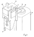
- the desk shown in fig. 1 comprises a lifting column 1 at each end.
- the lifting column 1 consists of three mutually telescopic members 2a, 2b, 2c and are firmly mounted in a foot 3 with the lower end of the outer member 2a, which is connected with a cross member 4 at the upper end.
- the tabletop 5 is mounted on the upper end of the inner member 2c of the lifting columns.
- the movement of the columns is caused by an incorporated drive unit 8, which is driven by an electric motor which is connected with a control box 6 with a power supply.
- the box also contains a control which is activated by a control panel 7 arranged at the front edge of the table.
- the control may be based on rotary potentiometers, optical or magnetic encoders for determining the height of the tabletop or purely electronically, as stated in WO 02/091539 .
- the drive unit 8 is of the type which is defined in the applicant's international application PCT/DK02/00467 , which is hereby incorporated by reference in the present application.
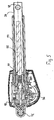
- the structure of the drive unit will now be described briefly for the sake of good order. It is based on a rod-shaped element 9 having a chain which extends around a gear wheel at each end. The one gear wheel is driven via a gearing by a DC motor 10 secured to the end of the rod.
- a rod 13, 14 is secured to each chain run 11, 12 between the two gear wheels, said rod being secured to the outer member 2a and to the inner member 2c, respectively.
- the motor When the motor is activated, the two rods 13, 14 will synchronously extend the outer profile 2a and the inner profile 2c relative to the intermediate profile 2b as a consequence of the movement of the chain and correspondingly retract them when the rotation of the motor is turned.
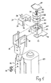
- the end of the rod 14 has mounted thereon a unit 15 containing a passive sound generator with a piezo element.
- the unit comprises a substantially U-shaped frame 16 which fits over the end of the rod 14 and is secured thereto with a pair of rivets 1.
- a housing 19 having a cylindrical interior may be inserted into an opening 18 of the frame, and a capsule 20 resting on a flange 21 may be accommodated in said housing.
- the capsule contains a passive sound generator in the form of a thin, circular, elastic metal plate on which a piezo element is arranged, e.g. a kbs-20db-4p.
- a pair of disc springs 22 rest above the capsule 20.
- a screw spring 23 rests with one end on the passive sound generator, said spring 23 extending through a circular recess 24 at the top of the capsule 20 and further through a circular recess 25 in the disc springs and provided at the other end with a pressure shoe 26 having a short control pin, which extends into the spring, and the upper side of the head of the pressure shoe has an engagement bead which is received in a recess in the cover so that it is guided.
- a cover 27 is arranged on the disc springs 22 and the pressure shoe 26 of the screw spring, said cover being guided in a recess 28 at the top of the housing 19 and with side edges on the upper side for guidance in the recess 18 in the frame 16.
- the cover 27 is kept in position by a lid 29 which engages below an edge 32 on the housing 19 with a pair of legs 30 terminating with flanges 31 facing toward each other.
- the length of the legs 30 is adapted such that the lid 29 is allowed to travel.
- the springs press the cover and thereby the lid 29 upwards, so that the lid grips the flanges 32 on the housing with its edges 31.
- a U-shaped metal bracket 33 is secured in the lid 29, having two upwardly extending legs for attachment to the inner member 2c of the column. This takes place over an end plate by which the column is secured to the tabletop. The metal bracket thus replaces the two flaps on the rod 14.
- the jamming protection as a unit may thus be mounted readily on the drive unit without any modifications to the mounting brackets being required.
- the drive unit with the jamming protection may thus be mounted selectively.
- a small printed circuit board 34 with terminals for the acoustic sound generator and connection to the control 6.
- the attachment may be performed with a small guide pin on the lid and a screw, screw holes being indicated at the side of the guide pin.
- the spring constant of the screw spring 23 and the disc springs 22 is adapted so that just a small portion of the force is transferred to the screw spring and thereby the acoustic sound generator.
- the tabletop rests with its weight on the lid 29, which is carried above the cover 27 by the disc springs 22. It will be appreciated that these springs 22 are dimensioned to carry the weight of the tabletop and the load thereon. If the tabletop meets an obstacle during an upward movement, the force on the springs 22 will be increased, and the force of the screw spring 23 on the acoustic sound generator will be increased correspondingly, thereby signalling the control 6 to change the force on the tabletop.
- the control is adapted to stop the drive unit and reverse briefly for retraction (lowering) of the tabletop from the encountered obstacle.
- the mechanical brackets will prevent destruction of the passive sound generator. If the table is loaded strongly from above, the underside of the lid 29 will hit the upper side of the housing 19, and, conversely, if e.g. during moving and handling of the table a strong upwardly directed force is unintentionally applied to the lower side of the tabletop or the legs are pulled, then the flanges 31 on the lid 29 will engage the edges 32 on the housing 19.
- the actuator comprises a spindle 35 which is driven by a DC motor via a worm gear 36.
- the spindle has a nut 37 with an activation element in the form of an inner pipe 38 guided in an outer pipe 39.
- a compressive bearing 40 in the present case a ball bearing, is arranged on the end of the spindle to absorb the compressive forces occurring on the actuator.
- the jamming protection arrangement may be arranged immediately behind the compressive bearing, or in connection with the rear attachment 41 of the actuator, in the alternative at the outer end 42 of the inner pipe 38. The same, of course, applies to actuators which operate under tension, which merely differ by having a tensile bearing instead of a compressive bearing.
- the invention provides a completely new path for the provision of jamming protection in an adjustable structure or the drive unit which operates it.
- Figs. 6-8 of the drawing show a cross-section of three other embodiments of the invention, and the same parts are designated by the same reference numerals as above.
- the passive sound generator comprises a disc 20a with a piezo element resting on a disc-shaped spring element 20b.
- the piezo element is here affected directly by a pin 23a on the lid 29.
- the pin may very well be formed with an outer spring-loaded, telescopic part so as to achieve a gearing, as described earlier.
- the housing is here secured to the stationary part of the structure and the lid with the pin to the movable element.
- the structure may be provided as a unit intended for incorporation, where the housing may e.g.
- the disc-shaped spring element with the piezo element 20a rests on a corrugated disc 20c. Connection wires to the piezo element and the pin are indicated at 43a, 43b.
- the housing which is circular here, has an annular flange 32 which cooperates with a flange 31 a on a surrounding ring 30a. This ring 30a is provided with screw holes for attachment of the ring to the movable part.
- the lid 29 may be secured to the stationary part by a downwardly extending pin 44.
- the embodiment shown in fig. 8 differs in that the piezo element 20d is a ring mounted between two discs 45. There is an air gap between a surrounding ring 46 and a disc 47. The pressure from the two disc springs 22 will propagate through the intermediate discs to the piezo element 20d.
- the jamming protection has no direct relation to end stops in actuators or their quick release function (EP 577 541 B1 to Linak A/S). These functions may occur concurrently with the jamming protection.
Landscapes
- Apparatuses For Generation Of Mechanical Vibrations (AREA)
- Catching Or Destruction (AREA)
- Emergency Protection Circuit Devices (AREA)
- Mechanical Light Control Or Optical Switches (AREA)
- Elimination Of Static Electricity (AREA)
- General Electrical Machinery Utilizing Piezoelectricity, Electrostriction Or Magnetostriction (AREA)
- Gripping Jigs, Holding Jigs, And Positioning Jigs (AREA)
- Clamps And Clips (AREA)
- Vibration Prevention Devices (AREA)
- Structures Of Non-Positive Displacement Pumps (AREA)
Abstract
Description
- The present invention relates to a structure of the type defined in the introductory portion of claim 1 and a jamming protection arrangement as well as a drive unit therefor.
- A widely used drive unit for performing adjustments is linear actuators, where an electric motor, via a gearing, drives a spindle having a nut movable in the axial direction to which an activation element is secured, cf. e.g.
EP 622 573 B1 WO 96/12123 PCT/DK02/00476 WO 01/17401 A1 - These actuators find general application, examples of use being for adjustable articles of furniture (e.g. chairs, beds, tables), hospital and nursing equipment (e.g. hospital beds and sickbeds, patient lifters) and industrial equipment (e.g. agricultural machinery, conveyors, process systems, barrier and bar systems) just to mention a few examples.
- Performance of an adjustment involves a risk of an object getting into the path of movement of the element, or there might be something in the structure itself that counteracts the movement. In this respect, a distinction is made here between a blocking protection arrangement which is basically aimed at protecting the structure, and a jamming protection arrangement which is basically aimed at protecting an object which inadvertently enters the path of movement of the element. What is in mind here is primarily avoidance of injury to individuals.
- For blocking protection, various solutions are known, such as overloading couplings (
US 4 846 011 ), detection of an increase in the motor current or detection of the speed of rotation of either the motor or of the gearing. In many cases the blocking protection is also used in linear actuators, also as an end stop. Mention may here be made of a special structure where a contact arm acts against a spring force, cf.US 4 307 799 to Andco Actuator Products andEP 727 601 - As mentioned, the jamming protection is aimed at protecting the very object that gets jammed. An example of a jamming protection arrangement is provided in
WO 01/117400 - A particular problem is jamming protection in height-adjustable tables which must ideally be active both when the tabletop is lowered and raised. When the tabletop is raised, it may e.g. hit an adjacent table, a window frame or a shelf. Jamming protection is very important particularly when the table is present in a home with small children.
-
US 5 495 811 discloses two different solutions, one where the tabletop is arranged loosely in a frame and rests on a contact. If the tabletop meets an obstacle in a downward direction, the tabletop is lifted and the contact is activated to interrupt the current to the motor. Inexpediently, the tabletop rests with its entire weight and load (as aguideline 100 kg) on the object which has got jammed. The solution does not either allow for the fact that the carrying frame hits an obstacle, nor is it active in the upward direction of the tabletop either. The other solution is based on the so-called tape switches which are adhered to the underside of the table. These are not active in the upward direction of the table either. -
SE 516 479 C2 - The object of the invention is to provide a jamming protection arrangement which primarily offers a more complete protection, and is simpler and easier to incorporate than the previously known ones.
- This is achieved according to the invention by a structure which is characterized by comprising a piezo element arranged in connection with one of the attachment points of the drive unit or in the drive unit itself to record deviations in the force extending between the attachment points of the drive unit. Thus, the piezo element is not used for making absolute measurements, but exclusively for recording deviations on the basis of concrete situations. The absolute force to be moved by the drive unit may basically be different from time to time, which is of minor importance. The essential point is that during movement the piezo element records deviations in the initial load to indicate that the adjustment element meets an obstacle and then stops/reverses the motor. Limit values may be fixed as to how great deviations of the force may be tolerated before this is taken to mean that the structure meets an obstacle.
- In this connection it is particularly expedient that transient signals from the piezo element are ignored or suppressed during starting of the drive unit to eliminate the special forces that occur during start. This may be the transition from static to dynamic function, overcoming of forces of inertia, or a "binding"/"rooting" when the structure has been at a standstill, and similar forces. Of course, the time of using the signal from the piezo element may be adapted to the actual structure, force application and speed at which the drive units runs. It will be appreciated that the transient phenomenon is quite brief (typically milliseconds), so that in reality there will be no time for jamming to occur.
- In this connection it is noted that the controls are typically, but not exclusively microprocessor-based, thereby allowing desired threshold and limit values to be incorporated in terms of software. In case of controls not based on microprocessors, threshold and limit values may be provided electronically.
- In case of height-adjustable tables, e.g., the force may be varied by removing or putting an object on the table. When the height of the table is adjusted, the force may be different from time to time, which is of minor importance. With the given initial load (force), the piezo element will exclusively record deviations in the force during the adjustment itself, if the tabletop meets an obstacle in a downward or upward direction.
- The solution of the invention is also independent on how the load is distributed on the adjustable element, e.g. on a tabletop there are typically local loads e.g. in the form of a computer, stacks of paper, etc. The essential point is exclusively the resulting force on the piezo element.
- The type of the piezo element is adapted to the structure concerned, but it has been found to be particularly expedient to use a passive sound generator containing a piezo element. These are generally known and are widely used for emitting a brief sound, e.g. the well-known beep sounds in the operation of electronic apparatuses. The passive sound generator is advantageous in that the piezo element is arranged on a thin, flexible disc of metal, so that a useful signal will be obtained even with the application of a relatively low force. Relative to a ceramic disc or block-shaped piezo element which is to be specially designed for the given purpose, the passive sound generator is a general and inexpensive component.
- To avoid destruction of the piezo element by overloading, mechanical stops may be incorporated in the structure which limit the travel of the piezo element.
- Further, the structure may be formed with a gearing so that just a minor directly proportional part of the load is transferred to the piezo element. Such a gearing might be sets of springs, where one set is in contact with the piezo element and has a spring constant smaller than the other set of springs between the stationary and movable parts of the structure. It will be appreciated in this connection that the drive unit may be associated fully or partly with the one or the other part.
- The location of the piezo element(s) is adapted to the structure concerned.
- In connection with the attachment of the drive unit, a piezo element might be provided which recorded any change in the force on the drive unit. In height-adjustable tables, a piezo element might be arranged below each leg. In tables having a cross member between the legs, however, it should be positioned so as to allow avoidance of jamming between the tabletop and the cross member. Expediently, the pressure transducer is arranged in the line of force between the attachment points of the drive unit, thereby achieving the most direct impact on the piezo element.
- Particularly expediently, the piezo element is incorporated in the drive unit, viz. in connection with a force absorbing bearing in the actuator. Hereby, the drive unit may be supplied as a finished and thoroughly tested unit, which obviates separate subsequent mounting of the piezo element in the structure and the consequent drawbacks.
- How the braking is to take place may be adapted to the structure concerned, just as it may be decided whether reversing of the drive unit is to be carried out. A simple and safe solution is short-circuiting of the motor windings. If rapid stopping of the drive unit is required, the control may be adapted such that the rotation of the motor is turned so as to provide active braking. It may then be decided whether reversing proper of the drive unit is to take place. Also, a brake proper may be incorporated in the drive unit or overall in the structure, e.g. a type which is activated by a solenoid.
- As stated in
claim 20, the invention also relates to a jamming protection arrangement, and, as stated inclaim 21, the invention moreover relates to a drive unit with an incorporated or mounted jamming protection unit as defined inclaim 20. - An embodiment of the invention in the form of a height-adjustable table will be explained more fully below with reference to the accompanying drawing. In the drawing:
-
Fig. 1 shows a schematic view of a height-adjustable table, where the tabletop is shown transparent, and with the drive units shown separate in a retracted state, -
fig. 2 shows a drive unit in a fully extended state, -
fig. 3 shows a jamming protection unit with a piezo element mounted on the outer end of the upper rod in the drive unit, -
fig. 4 shows an exploded view of the jamming protection unit with a piezo element shown infig. 2 , -
fig. 5 shows a longitudinal section through a linear actuator, -
fig. 6 shows a cross-section through another embodiment of the invention, -
fig. 7 shows a cross-section through an embodiment similar to the one offig. 6 , and -
fig. 8 shows a cross-section through a further embodiment of the invention. - The desk shown in
fig. 1 comprises a lifting column 1 at each end. The lifting column 1 consists of three mutuallytelescopic members 2a, 2b, 2c and are firmly mounted in afoot 3 with the lower end of the outer member 2a, which is connected with across member 4 at the upper end. Thetabletop 5 is mounted on the upper end of theinner member 2c of the lifting columns. - The movement of the columns is caused by an incorporated
drive unit 8, which is driven by an electric motor which is connected with acontrol box 6 with a power supply. The box also contains a control which is activated by acontrol panel 7 arranged at the front edge of the table. The control may be based on rotary potentiometers, optical or magnetic encoders for determining the height of the tabletop or purely electronically, as stated inWO 02/091539 - The
drive unit 8 is of the type which is defined in the applicant's international applicationPCT/DK02/00467 - The structure of the drive unit will now be described briefly for the sake of good order. It is based on a rod-shaped element 9 having a chain which extends around a gear wheel at each end. The one gear wheel is driven via a gearing by a
DC motor 10 secured to the end of the rod. Arod chain run inner member 2c, respectively. When the motor is activated, the tworods inner profile 2c relative to the intermediate profile 2b as a consequence of the movement of the chain and correspondingly retract them when the rotation of the motor is turned. Reference is made to said international application for a more detailed explanation of the drive unit. - As will appear from
figs. 3 and4 , the end of therod 14 has mounted thereon aunit 15 containing a passive sound generator with a piezo element. The unit comprises a substantiallyU-shaped frame 16 which fits over the end of therod 14 and is secured thereto with a pair of rivets 1. Ahousing 19 having a cylindrical interior may be inserted into anopening 18 of the frame, and acapsule 20 resting on aflange 21 may be accommodated in said housing. The capsule contains a passive sound generator in the form of a thin, circular, elastic metal plate on which a piezo element is arranged, e.g. a kbs-20db-4p. A pair of disc springs 22 rest above thecapsule 20. Ascrew spring 23 rests with one end on the passive sound generator, saidspring 23 extending through acircular recess 24 at the top of thecapsule 20 and further through acircular recess 25 in the disc springs and provided at the other end with apressure shoe 26 having a short control pin, which extends into the spring, and the upper side of the head of the pressure shoe has an engagement bead which is received in a recess in the cover so that it is guided. Acover 27 is arranged on the disc springs 22 and thepressure shoe 26 of the screw spring, said cover being guided in arecess 28 at the top of thehousing 19 and with side edges on the upper side for guidance in therecess 18 in theframe 16. Thecover 27 is kept in position by alid 29 which engages below anedge 32 on thehousing 19 with a pair oflegs 30 terminating withflanges 31 facing toward each other. The length of thelegs 30 is adapted such that thelid 29 is allowed to travel. In a non-loaded state, the springs press the cover and thereby thelid 29 upwards, so that the lid grips theflanges 32 on the housing with itsedges 31. AU-shaped metal bracket 33 is secured in thelid 29, having two upwardly extending legs for attachment to theinner member 2c of the column. This takes place over an end plate by which the column is secured to the tabletop. The metal bracket thus replaces the two flaps on therod 14. The jamming protection as a unit may thus be mounted readily on the drive unit without any modifications to the mounting brackets being required. Thus, the drive unit with the jamming protection may thus be mounted selectively. Below thehousing 19 there is mounted a small printedcircuit board 34 with terminals for the acoustic sound generator and connection to thecontrol 6. As an alternative to the metal bracket, the attachment may be performed with a small guide pin on the lid and a screw, screw holes being indicated at the side of the guide pin. - The spring constant of the
screw spring 23 and the disc springs 22 is adapted so that just a small portion of the force is transferred to the screw spring and thereby the acoustic sound generator. - The tabletop rests with its weight on the
lid 29, which is carried above thecover 27 by the disc springs 22. It will be appreciated that thesesprings 22 are dimensioned to carry the weight of the tabletop and the load thereon. If the tabletop meets an obstacle during an upward movement, the force on thesprings 22 will be increased, and the force of thescrew spring 23 on the acoustic sound generator will be increased correspondingly, thereby signalling thecontrol 6 to change the force on the tabletop. The control is adapted to stop the drive unit and reverse briefly for retraction (lowering) of the tabletop from the encountered obstacle. If during a lowering movement the tabletop meets an obstacle, this will cause an initial relief, whereby the force of thescrew spring 23 on the passive sound generator is relieved, and a change in the force is recorded. Thecontrol 6 is then signalled to stop thedrive unit 8 and reverse briefly to raise the tabletop, thereby releasing the object which got jammed. It will be appreciated that the tabletop only affects the obstacle with a minor inconsiderable weight, i.e. the tabletop will never hang on the obstacle with its full weight. - If the table should be overloaded with an extreme force, then the mechanical brackets will prevent destruction of the passive sound generator. If the table is loaded strongly from above, the underside of the
lid 29 will hit the upper side of thehousing 19, and, conversely, if e.g. during moving and handling of the table a strong upwardly directed force is unintentionally applied to the lower side of the tabletop or the legs are pulled, then theflanges 31 on thelid 29 will engage theedges 32 on thehousing 19. - It will be appreciated that the invention may also be applied in an actuator of the type defined in the applicant's
international application WO 02/29284 - With reference to
fig. 5 , it will briefly be summarized that the actuator comprises aspindle 35 which is driven by a DC motor via aworm gear 36. The spindle has anut 37 with an activation element in the form of aninner pipe 38 guided in anouter pipe 39. A compressive bearing 40, in the present case a ball bearing, is arranged on the end of the spindle to absorb the compressive forces occurring on the actuator. With suitable modification, the jamming protection arrangement may be arranged immediately behind the compressive bearing, or in connection with therear attachment 41 of the actuator, in the alternative at theouter end 42 of theinner pipe 38. The same, of course, applies to actuators which operate under tension, which merely differ by having a tensile bearing instead of a compressive bearing. - As will appear, the invention provides a completely new path for the provision of jamming protection in an adjustable structure or the drive unit which operates it.
-
Figs. 6-8 of the drawing show a cross-section of three other embodiments of the invention, and the same parts are designated by the same reference numerals as above. With respect to the embodiment infig. 6 it is noted that the passive sound generator comprises adisc 20a with a piezo element resting on a disc-shaped spring element 20b. The piezo element is here affected directly by apin 23a on thelid 29. It is noted that the pin may very well be formed with an outer spring-loaded, telescopic part so as to achieve a gearing, as described earlier. The housing is here secured to the stationary part of the structure and the lid with the pin to the movable element. The structure may be provided as a unit intended for incorporation, where the housing may e.g. be mounted in a support for a tabletop and the lid with the pin is secured to the lower side of the tabletop. The disc springs 23, here arranged between two washers, carry the weight of the tabletop. In the embodiment shown infig. 7 , the disc-shaped spring element with thepiezo element 20a rests on acorrugated disc 20c. Connection wires to the piezo element and the pin are indicated at 43a, 43b. The housing, which is circular here, has anannular flange 32 which cooperates with a flange 31 a on asurrounding ring 30a. Thisring 30a is provided with screw holes for attachment of the ring to the movable part. Here, thelid 29 may be secured to the stationary part by a downwardly extendingpin 44. The embodiment shown infig. 8 differs in that thepiezo element 20d is a ring mounted between twodiscs 45. There is an air gap between a surroundingring 46 and adisc 47. The pressure from the two disc springs 22 will propagate through the intermediate discs to thepiezo element 20d. - Disc springs are used in the stated examples, but nothing prevents the use of screw springs, but the disc springs are more suitable in the present
- Finally, it should be noted that the jamming protection has no direct relation to end stops in actuators or their quick release function (
EP 577 541 B1
Claims (21)
- An article of furniture, comprising:a stationary part (1, 3),an adjustable element (5) connected therewith,a drive unit (8) for causing the adjustment of the element (5), said drive unit (8) with a movable activation element (14; 38) and another part (13; 41) being secured to the adjustable element and to the stationary part, respectively, said drive unit comprising an electric motor (10) for the driving thereof,a control unit (6) for controlling the drive unit,a sensor (15) connected to the control to currently record deviations in the load on the adjustable element in operation and, in response to this, to signal the control unit to stop/reverse the motor,characterized in that
the sensor is formed by a piezo element (20) arranged in connection with one of the attachment points of the drive unit (8) or in the drive unit itself to record deviations in the force extending between the attachment points of the drive unit. - An article of furniture according to claim 1, characterized in that the signals from the piezo element are ignored during the start of the drive unit.
- An article of furniture according to claim 1, characterized in that the signals from the piezo element are used only when these have found a constant level after the start of the drive unit.
- An article of furniture according to claim 1, characterized in that the piezo element is positioned at a location in the line of force between the attachment points of the drive unit.
- An article of furniture according to claim 1, characterized in that the piezo element is arranged in connection with a force absorbing bearing (40) in the drive unit.
- An article of furniture according to claim 1,characterized in that it comprises a passive sound generator (20) containing a piezo element as a sensor.
- An article of furniture according to one of claims 1-6, characterized in that it comprises mechanical stops (31, 32; 29, 19) which limit the travel of the piezo element.
- An article of furniture according to one of claims 1-7, characterized in that it comprises a gearing so that just a minor directly proportional part of the force is transferred to the piezo element.
- An article of furniture according to claim 8, characterized in that the gearing comprises a set of springs, where one spring (23) is in contact with the piezo element and has a spring constant smaller than the other spring (22) between the stationary and movable parts of the structure.
- An article of furniture according to claim 8, characterized in that the spring (22) is formed by disc springs, while the other spring (23) is formed by a screw spring.
- An article of furniture according to claim 9 or 10, characterized in that the spring (22) is dimensioned to carry the weight of the movable part and the maximum weight which the part is intended to be capable of carrying.
- An article of furniture according to one of claims 1-12, characterized in that the jamming protection arrangement is provided as a unit comprising a housing (19) which accommodates the piezo element (20).
- An article of furniture according to claim 12, characterized in that the housing (19) comprises a lid (29) with legs (30) formed with abutments (31) for cooperation with abutments (31) on the housing to limit the travel of the lid.
- An article of furniture according to claim 13, characterized in that the springs (22, 23) are accommodated in the housing, and that the spring (22) pushes the lid (29) away from the housing.
- An article of furniture according to claim 12, characterized in that the jamming protection arrangement comprises a frame (16) for the housing (19).
- An article of furniture according to claim 15, characterized in that the housing (19) is received in a recess (18) in the frame.
- An article of furniture according to claim 12, characterized in that the jamming protection arrangement comprises a printed circuit board (34) for the connection of the piezo element and for the connection of the control (6).
- An article of furniture according to claim 12, characterized in that the jamming protection arrangement is provided with mounting brackets for the mounting of the movable element (15).
- An article of furniture according to claim 12, characterized in that the jamming protection arrangement is mounted on the end of the activation element (14; 38) of the drive unit.
- A jamming protection arrangement for a drive unit (8), said drive unit (8) having a movable activation element (14; 38) with a first attachment point and another part (13; 41) with a second attachment point, an electric motor (10) for driving the activation element, a control unit (6) for controlling the drive unit, said jamming protection arrangement comprising a sensor (15) connected to the control to currently record deviations in the load on the drive unit and to signal to the control unit to stop/reverse the motor at a certain deviation of the load, and wherein the sensor is formed by a piezo element (20) arranged in connection with one of the attachment points of the drive unit (8) or in the drive unit itself to record deviations in the force extending between the attachment points of the drive unit.
- A drive unit having an incorporated or mounted jamming protection arrangement as defined in claim 20.
Priority Applications (1)
| Application Number | Priority Date | Filing Date | Title |
|---|---|---|---|
| DE60225335.7T DE60225335T3 (en) | 2001-12-13 | 2002-12-13 | ADJUSTABLE CONSTRUCTION, PREFERABLY A PIECE OF FURNITURE, AND AN ANTI-PINCH PROTECTION AND DRIVE UNIT FOR IT |
Applications Claiming Priority (3)
| Application Number | Priority Date | Filing Date | Title |
|---|---|---|---|
| DKPA200101871 | 2001-12-13 | ||
| DK200101871 | 2001-12-13 | ||
| PCT/DK2002/000855 WO2003056976A1 (en) | 2001-12-13 | 2002-12-13 | An adjustable construction preferably an article of furniture and a squeeze protection and a drive unit thereto |
Publications (3)
| Publication Number | Publication Date |
|---|---|
| EP1460914A1 EP1460914A1 (en) | 2004-09-29 |
| EP1460914B1 true EP1460914B1 (en) | 2008-02-27 |
| EP1460914B2 EP1460914B2 (en) | 2021-05-26 |
Family
ID=8160898
Family Applications (1)
| Application Number | Title | Priority Date | Filing Date |
|---|---|---|---|
| EP02792704.5A Expired - Lifetime EP1460914B2 (en) | 2001-12-13 | 2002-12-13 | An adjustable construction preferably an article of furniture and a squeeze protection and a drive unit thereto |
Country Status (8)
| Country | Link |
|---|---|
| US (1) | US7049728B2 (en) |
| EP (1) | EP1460914B2 (en) |
| AT (1) | ATE387125T1 (en) |
| AU (1) | AU2002358460A1 (en) |
| DE (1) | DE60225335T3 (en) |
| DK (1) | DK1460914T4 (en) |
| ES (1) | ES2299621T3 (en) |
| WO (1) | WO2003056976A1 (en) |
Cited By (3)
| Publication number | Priority date | Publication date | Assignee | Title |
|---|---|---|---|---|
| EP2583586A1 (en) | 2011-10-18 | 2013-04-24 | Kesseböhmer Produktions GmbH + Co. KG | Device for detecting collisions and method |
| DE102014221265A1 (en) | 2014-10-20 | 2016-04-21 | Kesseböhmer Produktions GmbH & Co. KG | Mechanism for controlling a height-adjustable furniture, in particular a table, and corresponding method therefor |
| US9993069B2 (en) | 2016-03-15 | 2018-06-12 | Kesseböhmer Produktions GmbH & Co. KG | Steering mechanism for height-adjustable furniture, in particular tables, and method thereto |
Families Citing this family (35)
| Publication number | Priority date | Publication date | Assignee | Title |
|---|---|---|---|---|
| CN1882302B (en) * | 2003-11-18 | 2010-04-28 | 利纳克有限公司 | Hospital or nursing bed |
| US7677678B2 (en) * | 2004-06-09 | 2010-03-16 | Spectrum Industries Inc. | Wheelchair accommodating system |
| AT501146B8 (en) | 2005-03-25 | 2007-02-15 | Logicdata Elect & Software Ent | BENCH |
| US8240257B2 (en) * | 2005-04-14 | 2012-08-14 | Linak A/S | Article of furniture, in particular a sitting/standing table |
| DK1947981T3 (en) | 2005-10-18 | 2017-07-03 | Linak As | Linear actuator |
| DK176598B1 (en) * | 2006-02-10 | 2008-10-20 | Jesper Oestergaard Kristensen | Telescopic lifting column for height adjustment of pupilable tables |
| DE202006007006U1 (en) * | 2006-04-24 | 2006-07-06 | Kesseböhmer Produktions GmbH & Co. KG | Telescopic leg for table, chair, or bench, comprising base with extended upper area covering connection zone between base and leg |
| EP2027642A1 (en) * | 2006-06-13 | 2009-02-25 | Linak A/S | Actuator |
| CN102056514B (en) * | 2008-06-06 | 2013-06-12 | 利纳克有限公司 | Linear actuator |
| SE0802030L (en) * | 2008-09-24 | 2009-11-17 | Swedestyle Ab | Device for mounting a table top on a rack with drive means |
| DK200901249A (en) | 2009-11-26 | 2011-05-27 | Linak As | Linear actuator with clamp protection |
| DE202010015737U1 (en) | 2009-11-26 | 2011-04-07 | Linak A/S | Linear drive and piece of furniture each with a device for locking or clamping detection |
| DE102009058422B4 (en) | 2009-12-16 | 2015-05-07 | Logicdata Electronic & Software Entwicklungs Gmbh | Apparatus and method for collision detection of a movable furniture portion with an obstacle |
| US9375081B2 (en) | 2009-12-17 | 2016-06-28 | Linak A/S | Wall-mounted cabinet |
| DK2452589T3 (en) * | 2010-11-13 | 2014-07-21 | Linak As | Electric actuator system |
| EP2841897B1 (en) * | 2012-04-23 | 2021-12-15 | Linak A/S | Linear actuator |
| US10827829B1 (en) | 2012-10-10 | 2020-11-10 | Steelcase Inc. | Height adjustable support surface and system for encouraging human movement and promoting wellness |
| US12376677B1 (en) | 2012-10-10 | 2025-08-05 | Steelcase Inc. | Ergonomic seating system, tilt-lock control and remote powering method and apparatus |
| DE102013107053B4 (en) * | 2013-03-22 | 2015-04-09 | Logicdata Electronic & Software Entwicklungs Gmbh | Operating device for an electrically height-adjustable table, electrically height-adjustable table, drive system for an electrically height-adjustable table and method for height adjustment of a table top of a table |
| KR102053015B1 (en) * | 2015-04-23 | 2020-01-08 | 티모션 테크놀로지 코., 엘티디. | Electrical Adjustable Table and Control Method for Electrical Adjustable Table |
| CN106483985B (en) | 2015-08-24 | 2020-09-08 | 第一传动科技股份有限公司 | Portable device for controlling lifting equipment and lifting equipment control method |
| WO2017079917A1 (en) * | 2015-11-11 | 2017-05-18 | La (Linear Adjustment) Dev. Limited | Telescopic support device for furniture |
| DE202016105266U1 (en) * | 2016-09-21 | 2017-12-22 | Dewertokin Gmbh | Electromotive furniture drive |
| US11019920B2 (en) | 2016-09-23 | 2021-06-01 | Varidesk, Llc | Electrically-lifted computer desk and office desk thereof |
| CN206390562U (en) | 2016-09-23 | 2017-08-11 | 廖良成 | Electric lifting computer desk and its desk |
| US10470563B2 (en) | 2017-05-24 | 2019-11-12 | Vitra Patente Ag | Height-adjustable piece of furniture and cable protector for such a piece of furniture |
| DE102018109215A1 (en) | 2018-04-18 | 2019-10-24 | Logicdata Electronic & Software Entwicklungs Gmbh | Sensor assembly, actuator, controller, electrically adjustable piece of furniture and method of operating an electrically adjustable piece of furniture |
| CN109452758B (en) * | 2018-11-20 | 2024-02-09 | 裴旭波 | Pneumatic lifting table |
| CN110250739A (en) * | 2019-04-18 | 2019-09-20 | 美国乐歌有限公司 | Control system and method for electric lift table that realizes retreat in case of resistance |
| US10912380B1 (en) * | 2019-09-20 | 2021-02-09 | Dong Guan Song Wei Electric Technology Co., Ltd. | Height-adjustable table with stop control system |
| CA3095809A1 (en) | 2019-10-22 | 2021-04-22 | Thorlabs, Inc. | Motorized, height adjustable optical table with rigid, passive and active isolation |
| CN110916345A (en) * | 2019-11-27 | 2020-03-27 | 熊子轩 | Learning desk |
| CN113833817A (en) * | 2021-09-10 | 2021-12-24 | 德沃康科技集团有限公司 | a linear actuator |
| EP4704644A1 (en) * | 2023-05-03 | 2026-03-11 | MillerKnoll, Inc. | User interface for height adjustable table |
| US12442436B2 (en) * | 2023-06-09 | 2025-10-14 | Timotion Technology Co., Ltd. | Linear actuator with protection mechanism |
Family Cites Families (8)
| Publication number | Priority date | Publication date | Assignee | Title |
|---|---|---|---|---|
| US3830103A (en) * | 1973-07-05 | 1974-08-20 | Us Army | Rain impact gage |
| NL7908078A (en) * | 1979-11-05 | 1981-06-01 | Herman Maurits Hoogstraat | Control panel for motorised wheel chair - has touch or pressure-sensitive sensors to control various motorised functions |
| JPH0822674B2 (en) * | 1987-04-07 | 1996-03-06 | 日野自動車工業株式会社 | Electric power steering |
| US5282711A (en) † | 1991-10-17 | 1994-02-01 | Association For Retarded Citizens Of The U.S. | Assistive dining device, system and method |
| SE521374C2 (en) * | 1999-09-09 | 2003-10-28 | Hl Display Ab | Pull-out shelf |
| DE19957187B4 (en) * | 1999-11-27 | 2007-05-10 | Volkswagen Ag | Method and device for crash detection |
| SE516479C2 (en) † | 2000-05-11 | 2002-01-22 | Artektron Ab | Device is for automatic stopping and-or reversing table top ascending movement to counteract jamming tendency, with table being raisable and lowerable by motor drive |
| AT410626B (en) † | 2002-02-26 | 2003-06-25 | Koch Walter Dipl Ing | Work table has controller that reverses direction of rotation of adjustment motor depending on detected parameter and/or motor load change, switches motor off after resulting reverse rotation |
-
2002
- 2002-12-13 EP EP02792704.5A patent/EP1460914B2/en not_active Expired - Lifetime
- 2002-12-13 DE DE60225335.7T patent/DE60225335T3/en not_active Expired - Lifetime
- 2002-12-13 AU AU2002358460A patent/AU2002358460A1/en not_active Abandoned
- 2002-12-13 US US10/497,690 patent/US7049728B2/en not_active Expired - Lifetime
- 2002-12-13 WO PCT/DK2002/000855 patent/WO2003056976A1/en not_active Ceased
- 2002-12-13 AT AT02792704T patent/ATE387125T1/en not_active IP Right Cessation
- 2002-12-13 DK DK02792704.5T patent/DK1460914T4/en active
- 2002-12-13 ES ES02792704T patent/ES2299621T3/en not_active Expired - Lifetime
Cited By (5)
| Publication number | Priority date | Publication date | Assignee | Title |
|---|---|---|---|---|
| EP2583586A1 (en) | 2011-10-18 | 2013-04-24 | Kesseböhmer Produktions GmbH + Co. KG | Device for detecting collisions and method |
| US9236817B2 (en) | 2011-10-18 | 2016-01-12 | Kessebohmer Produktions Gmbh & Co. Kg | Device for detecting collisions and a method related thereto |
| DE102014221265A1 (en) | 2014-10-20 | 2016-04-21 | Kesseböhmer Produktions GmbH & Co. KG | Mechanism for controlling a height-adjustable furniture, in particular a table, and corresponding method therefor |
| DE102014221265B4 (en) | 2014-10-20 | 2021-08-26 | Kesseböhmer Produktions GmbH & Co. KG | Mechanism for controlling a height-adjustable piece of furniture, in particular a table, and a corresponding method therefor |
| US9993069B2 (en) | 2016-03-15 | 2018-06-12 | Kesseböhmer Produktions GmbH & Co. KG | Steering mechanism for height-adjustable furniture, in particular tables, and method thereto |
Also Published As
| Publication number | Publication date |
|---|---|
| ES2299621T3 (en) | 2008-06-01 |
| AU2002358460A1 (en) | 2003-07-24 |
| WO2003056976A1 (en) | 2003-07-17 |
| ATE387125T1 (en) | 2008-03-15 |
| US7049728B2 (en) | 2006-05-23 |
| DE60225335T3 (en) | 2022-04-28 |
| DE60225335D1 (en) | 2008-04-10 |
| EP1460914B2 (en) | 2021-05-26 |
| DE60225335T2 (en) | 2009-02-26 |
| EP1460914A1 (en) | 2004-09-29 |
| DK1460914T3 (en) | 2008-06-09 |
| DK1460914T4 (en) | 2021-08-30 |
| US20050012430A1 (en) | 2005-01-20 |
Similar Documents
| Publication | Publication Date | Title |
|---|---|---|
| EP1460914B1 (en) | An adjustable construction preferably an article of furniture and a squeeze protection and a drive unit thereto | |
| EP2317892B1 (en) | Linear actuator | |
| US9236817B2 (en) | Device for detecting collisions and a method related thereto | |
| JP2005504605A (en) | Operating table | |
| US7971295B2 (en) | Protection for a lifting unit | |
| JP5687066B2 (en) | Actuator | |
| US3707930A (en) | Power operated pedestal table and safety clutch therefor | |
| EP4282302A3 (en) | Variable height platform system | |
| EP2174631A3 (en) | Hospital bed | |
| US20030146425A1 (en) | Lifting column, preferably for height adjustable furniture, such as beds and tables | |
| US6977476B2 (en) | Work table | |
| WO2019203999A1 (en) | Robotic surgical systems and robotic arm carts thereof | |
| TWI860255B (en) | Linear actuator with protection mechanism | |
| DE202005008523U1 (en) | Height adjustable bed or therapeutic bench, comprising safety function for downwards movement | |
| US20210239459A1 (en) | Sensor assembly, actuator, control system, electrically adjustable piece of furniture and method for operating an electrically adjustable piece of furniture | |
| KR20110137149A (en) | Height adjustment mechanism for kitchen furniture | |
| EP2299870B1 (en) | Adjustable article of furniture | |
| CA3095809A1 (en) | Motorized, height adjustable optical table with rigid, passive and active isolation | |
| US20220104915A1 (en) | Robotic surgical systems and robotic arm carts thereof | |
| KR20160058559A (en) | Lift table | |
| DE202007006673U1 (en) | Electrically height-adjustable table | |
| EP4709236A1 (en) | User interface for an adjustable article of furniture | |
| CA2088388A1 (en) | Safety device for an apparatus provided for lifting and lowering loads | |
| JPH0147397B2 (en) |
Legal Events
| Date | Code | Title | Description |
|---|---|---|---|
| PUAI | Public reference made under article 153(3) epc to a published international application that has entered the european phase |
Free format text: ORIGINAL CODE: 0009012 |
|
| 17P | Request for examination filed |
Effective date: 20040622 |
|
| AK | Designated contracting states |
Kind code of ref document: A1 Designated state(s): AT BE BG CH CY CZ DE DK EE ES FI FR GB GR IE IT LI LU MC NL PT SE SI SK TR |
|
| AX | Request for extension of the european patent |
Extension state: AL LT LV MK RO |
|
| 17Q | First examination report despatched |
Effective date: 20060320 |
|
| GRAP | Despatch of communication of intention to grant a patent |
Free format text: ORIGINAL CODE: EPIDOSNIGR1 |
|
| GRAS | Grant fee paid |
Free format text: ORIGINAL CODE: EPIDOSNIGR3 |
|
| GRAA | (expected) grant |
Free format text: ORIGINAL CODE: 0009210 |
|
| AK | Designated contracting states |
Kind code of ref document: B1 Designated state(s): AT BE BG CH CY CZ DE DK EE ES FI FR GB GR IE IT LI LU MC NL PT SE SI SK TR |
|
| REG | Reference to a national code |
Ref country code: GB Ref legal event code: FG4D |
|
| RIN1 | Information on inventor provided before grant (corrected) |
Inventor name: BASTHOLM, JEPPE |
|
| REG | Reference to a national code |
Ref country code: CH Ref legal event code: EP |
|
| REG | Reference to a national code |
Ref country code: IE Ref legal event code: FG4D |
|
| REF | Corresponds to: |
Ref document number: 60225335 Country of ref document: DE Date of ref document: 20080410 Kind code of ref document: P |
|
| REG | Reference to a national code |
Ref country code: CH Ref legal event code: NV Representative=s name: TROESCH SCHEIDEGGER WERNER AG |
|
| REG | Reference to a national code |
Ref country code: ES Ref legal event code: FG2A Ref document number: 2299621 Country of ref document: ES Kind code of ref document: T3 |
|
| REG | Reference to a national code |
Ref country code: DK Ref legal event code: T3 |
|
| REG | Reference to a national code |
Ref country code: SE Ref legal event code: TRGR |
|
| PG25 | Lapsed in a contracting state [announced via postgrant information from national office to epo] |
Ref country code: FI Free format text: LAPSE BECAUSE OF FAILURE TO SUBMIT A TRANSLATION OF THE DESCRIPTION OR TO PAY THE FEE WITHIN THE PRESCRIBED TIME-LIMIT Effective date: 20080227 |
|
| PG25 | Lapsed in a contracting state [announced via postgrant information from national office to epo] |
Ref country code: AT Free format text: LAPSE BECAUSE OF FAILURE TO SUBMIT A TRANSLATION OF THE DESCRIPTION OR TO PAY THE FEE WITHIN THE PRESCRIBED TIME-LIMIT Effective date: 20080227 |
|
| PG25 | Lapsed in a contracting state [announced via postgrant information from national office to epo] |
Ref country code: SI Free format text: LAPSE BECAUSE OF FAILURE TO SUBMIT A TRANSLATION OF THE DESCRIPTION OR TO PAY THE FEE WITHIN THE PRESCRIBED TIME-LIMIT Effective date: 20080227 |
|
| ET | Fr: translation filed | ||
| PG25 | Lapsed in a contracting state [announced via postgrant information from national office to epo] |
Ref country code: SK Free format text: LAPSE BECAUSE OF FAILURE TO SUBMIT A TRANSLATION OF THE DESCRIPTION OR TO PAY THE FEE WITHIN THE PRESCRIBED TIME-LIMIT Effective date: 20080227 Ref country code: PT Free format text: LAPSE BECAUSE OF FAILURE TO SUBMIT A TRANSLATION OF THE DESCRIPTION OR TO PAY THE FEE WITHIN THE PRESCRIBED TIME-LIMIT Effective date: 20080721 Ref country code: CZ Free format text: LAPSE BECAUSE OF FAILURE TO SUBMIT A TRANSLATION OF THE DESCRIPTION OR TO PAY THE FEE WITHIN THE PRESCRIBED TIME-LIMIT Effective date: 20080227 |
|
| PLBI | Opposition filed |
Free format text: ORIGINAL CODE: 0009260 |
|
| 26 | Opposition filed |
Opponent name: LOGICDATA ELECTRONIC&SOFTWARE ENTWICKLUNGS GMBH Effective date: 20081126 |
|
| PLAX | Notice of opposition and request to file observation + time limit sent |
Free format text: ORIGINAL CODE: EPIDOSNOBS2 |
|
| NLR1 | Nl: opposition has been filed with the epo |
Opponent name: LOGICDATA ELECTRONIC&SOFTWARE ENTWICKLUNGS GMBH |
|
| PG25 | Lapsed in a contracting state [announced via postgrant information from national office to epo] |
Ref country code: BG Free format text: LAPSE BECAUSE OF FAILURE TO SUBMIT A TRANSLATION OF THE DESCRIPTION OR TO PAY THE FEE WITHIN THE PRESCRIBED TIME-LIMIT Effective date: 20080527 Ref country code: EE Free format text: LAPSE BECAUSE OF FAILURE TO SUBMIT A TRANSLATION OF THE DESCRIPTION OR TO PAY THE FEE WITHIN THE PRESCRIBED TIME-LIMIT Effective date: 20080227 |
|
| PLAF | Information modified related to communication of a notice of opposition and request to file observations + time limit |
Free format text: ORIGINAL CODE: EPIDOSCOBS2 |
|
| PLBB | Reply of patent proprietor to notice(s) of opposition received |
Free format text: ORIGINAL CODE: EPIDOSNOBS3 |
|
| PG25 | Lapsed in a contracting state [announced via postgrant information from national office to epo] |
Ref country code: CY Free format text: LAPSE BECAUSE OF FAILURE TO SUBMIT A TRANSLATION OF THE DESCRIPTION OR TO PAY THE FEE WITHIN THE PRESCRIBED TIME-LIMIT Effective date: 20080227 Ref country code: MC Free format text: LAPSE BECAUSE OF NON-PAYMENT OF DUE FEES Effective date: 20081231 |
|
| PG25 | Lapsed in a contracting state [announced via postgrant information from national office to epo] |
Ref country code: IE Free format text: LAPSE BECAUSE OF NON-PAYMENT OF DUE FEES Effective date: 20081215 |
|
| PG25 | Lapsed in a contracting state [announced via postgrant information from national office to epo] |
Ref country code: LU Free format text: LAPSE BECAUSE OF NON-PAYMENT OF DUE FEES Effective date: 20081213 |
|
| PG25 | Lapsed in a contracting state [announced via postgrant information from national office to epo] |
Ref country code: TR Free format text: LAPSE BECAUSE OF FAILURE TO SUBMIT A TRANSLATION OF THE DESCRIPTION OR TO PAY THE FEE WITHIN THE PRESCRIBED TIME-LIMIT Effective date: 20080227 |
|
| PG25 | Lapsed in a contracting state [announced via postgrant information from national office to epo] |
Ref country code: GR Free format text: LAPSE BECAUSE OF FAILURE TO SUBMIT A TRANSLATION OF THE DESCRIPTION OR TO PAY THE FEE WITHIN THE PRESCRIBED TIME-LIMIT Effective date: 20080528 |
|
| APBM | Appeal reference recorded |
Free format text: ORIGINAL CODE: EPIDOSNREFNO |
|
| APBP | Date of receipt of notice of appeal recorded |
Free format text: ORIGINAL CODE: EPIDOSNNOA2O |
|
| APBM | Appeal reference recorded |
Free format text: ORIGINAL CODE: EPIDOSNREFNO |
|
| APBP | Date of receipt of notice of appeal recorded |
Free format text: ORIGINAL CODE: EPIDOSNNOA2O |
|
| APAH | Appeal reference modified |
Free format text: ORIGINAL CODE: EPIDOSCREFNO |
|
| APAW | Appeal reference deleted |
Free format text: ORIGINAL CODE: EPIDOSDREFNO |
|
| APBQ | Date of receipt of statement of grounds of appeal recorded |
Free format text: ORIGINAL CODE: EPIDOSNNOA3O |
|
| APBY | Invitation to file observations in appeal sent |
Free format text: ORIGINAL CODE: EPIDOSNOBA2O |
|
| PGFP | Annual fee paid to national office [announced via postgrant information from national office to epo] |
Ref country code: ES Payment date: 20141212 Year of fee payment: 13 Ref country code: GB Payment date: 20141219 Year of fee payment: 13 |
|
| PGFP | Annual fee paid to national office [announced via postgrant information from national office to epo] |
Ref country code: NL Payment date: 20141215 Year of fee payment: 13 |
|
| APCA | Receipt of observations in appeal recorded |
Free format text: ORIGINAL CODE: EPIDOSNOBA4O |
|
| APAR | Information on invitation to file observation in appeal modified |
Free format text: ORIGINAL CODE: EPIDOSCOBA2O |
|
| APBI | Information on receipt of observation in appeal deleted |
Free format text: ORIGINAL CODE: EPIDOSDOBA4O |
|
| PGFP | Annual fee paid to national office [announced via postgrant information from national office to epo] |
Ref country code: IT Payment date: 20141217 Year of fee payment: 13 |
|
| PGFP | Annual fee paid to national office [announced via postgrant information from national office to epo] |
Ref country code: FR Payment date: 20141231 Year of fee payment: 13 |
|
| PGFP | Annual fee paid to national office [announced via postgrant information from national office to epo] |
Ref country code: BE Payment date: 20141216 Year of fee payment: 13 |
|
| PLAB | Opposition data, opponent's data or that of the opponent's representative modified |
Free format text: ORIGINAL CODE: 0009299OPPO |
|
| R26 | Opposition filed (corrected) |
Opponent name: LOGICDATA ELECTRONIC&SOFTWARE ENTWICKLUNGS GMBH Effective date: 20081126 |
|
| APBU | Appeal procedure closed |
Free format text: ORIGINAL CODE: EPIDOSNNOA9O |
|
| PG25 | Lapsed in a contracting state [announced via postgrant information from national office to epo] |
Ref country code: BE Free format text: LAPSE BECAUSE OF NON-PAYMENT OF DUE FEES Effective date: 20151231 |
|
| GBPC | Gb: european patent ceased through non-payment of renewal fee |
Effective date: 20151213 |
|
| REG | Reference to a national code |
Ref country code: NL Ref legal event code: MM Effective date: 20160101 |
|
| REG | Reference to a national code |
Ref country code: FR Ref legal event code: ST Effective date: 20160831 |
|
| PG25 | Lapsed in a contracting state [announced via postgrant information from national office to epo] |
Ref country code: GB Free format text: LAPSE BECAUSE OF NON-PAYMENT OF DUE FEES Effective date: 20151213 Ref country code: NL Free format text: LAPSE BECAUSE OF NON-PAYMENT OF DUE FEES Effective date: 20160101 |
|
| PG25 | Lapsed in a contracting state [announced via postgrant information from national office to epo] |
Ref country code: FR Free format text: LAPSE BECAUSE OF NON-PAYMENT OF DUE FEES Effective date: 20151231 |
|
| PG25 | Lapsed in a contracting state [announced via postgrant information from national office to epo] |
Ref country code: IT Free format text: LAPSE BECAUSE OF NON-PAYMENT OF DUE FEES Effective date: 20151213 |
|
| REG | Reference to a national code |
Ref country code: ES Ref legal event code: FD2A Effective date: 20170127 |
|
| PG25 | Lapsed in a contracting state [announced via postgrant information from national office to epo] |
Ref country code: ES Free format text: LAPSE BECAUSE OF NON-PAYMENT OF DUE FEES Effective date: 20151214 |
|
| RAP2 | Party data changed (patent owner data changed or rights of a patent transferred) |
Owner name: LINAK A/S |
|
| APBM | Appeal reference recorded |
Free format text: ORIGINAL CODE: EPIDOSNREFNO |
|
| APBP | Date of receipt of notice of appeal recorded |
Free format text: ORIGINAL CODE: EPIDOSNNOA2O |
|
| APAH | Appeal reference modified |
Free format text: ORIGINAL CODE: EPIDOSCREFNO |
|
| APBQ | Date of receipt of statement of grounds of appeal recorded |
Free format text: ORIGINAL CODE: EPIDOSNNOA3O |
|
| REG | Reference to a national code |
Ref country code: DE Ref legal event code: R082 Ref document number: 60225335 Country of ref document: DE Representative=s name: KEIL & SCHAAFHAUSEN PATENTANWAELTE PARTGMBB, DE Ref country code: DE Ref legal event code: R082 Ref document number: 60225335 Country of ref document: DE Representative=s name: KEIL & SCHAAFHAUSEN PATENT- UND RECHTSANWAELTE, DE |
|
| APAH | Appeal reference modified |
Free format text: ORIGINAL CODE: EPIDOSCREFNO |
|
| APAH | Appeal reference modified |
Free format text: ORIGINAL CODE: EPIDOSCREFNO |
|
| APBU | Appeal procedure closed |
Free format text: ORIGINAL CODE: EPIDOSNNOA9O |
|
| PUAH | Patent maintained in amended form |
Free format text: ORIGINAL CODE: 0009272 |
|
| STAA | Information on the status of an ep patent application or granted ep patent |
Free format text: STATUS: PATENT MAINTAINED AS AMENDED |
|
| REG | Reference to a national code |
Ref country code: CH Ref legal event code: AELC |
|
| 27A | Patent maintained in amended form |
Effective date: 20210526 |
|
| AK | Designated contracting states |
Kind code of ref document: B2 Designated state(s): AT BE BG CH CY CZ DE DK EE ES FI FR GB GR IE IT LI LU MC NL PT SE SI SK TR |
|
| REG | Reference to a national code |
Ref country code: DE Ref legal event code: R102 Ref document number: 60225335 Country of ref document: DE |
|
| REG | Reference to a national code |
Ref country code: SE Ref legal event code: RPEO |
|
| REG | Reference to a national code |
Ref country code: DE Ref legal event code: R135 Ref document number: 60225335 Country of ref document: DE |
|
| REG | Reference to a national code |
Ref country code: DK Ref legal event code: T4 Effective date: 20210823 |
|
| PG25 | Lapsed in a contracting state [announced via postgrant information from national office to epo] |
Ref country code: DE Free format text: LAPSE BECAUSE OF FAILURE TO SUBMIT A TRANSLATION OF THE DESCRIPTION OR TO PAY THE FEE WITHIN THE PRESCRIBED TIME-LIMIT Effective date: 20210827 |
|
| PGFP | Annual fee paid to national office [announced via postgrant information from national office to epo] |
Ref country code: DK Payment date: 20211223 Year of fee payment: 20 Ref country code: SE Payment date: 20211221 Year of fee payment: 20 |
|
| PGFP | Annual fee paid to national office [announced via postgrant information from national office to epo] |
Ref country code: CH Payment date: 20211221 Year of fee payment: 20 |
|
| REG | Reference to a national code |
Ref country code: DE Ref legal event code: R073 Ref document number: 60225335 Country of ref document: DE |
|
| REG | Reference to a national code |
Ref country code: DE Ref legal event code: R074 Ref document number: 60225335 Country of ref document: DE |
|
| PG25 | Lapsed in a contracting state [announced via postgrant information from national office to epo] |
Ref country code: DE Free format text: LAPSE BECAUSE OF FAILURE TO SUBMIT A TRANSLATION OF THE DESCRIPTION OR TO PAY THE FEE WITHIN THE PRESCRIBED TIME-LIMIT Effective date: 20210827 |
|
| PGRI | Patent reinstated in contracting state [announced from national office to epo] |
Ref country code: DE Effective date: 20220319 |
|
| PGFP | Annual fee paid to national office [announced via postgrant information from national office to epo] |
Ref country code: DE Payment date: 20220406 Year of fee payment: 20 |
|
| REG | Reference to a national code |
Ref country code: DE Ref legal event code: R071 Ref document number: 60225335 Country of ref document: DE |
|
| REG | Reference to a national code |
Ref country code: CH Ref legal event code: PL |
|
| REG | Reference to a national code |
Ref country code: DK Ref legal event code: EUP Expiry date: 20221213 |
|
| REG | Reference to a national code |
Ref country code: SE Ref legal event code: EUG |