EP2583534B1 - Stromversorgung für ein magnetron - Google Patents
Stromversorgung für ein magnetron Download PDFInfo
- Publication number
- EP2583534B1 EP2583534B1 EP11741675.0A EP11741675A EP2583534B1 EP 2583534 B1 EP2583534 B1 EP 2583534B1 EP 11741675 A EP11741675 A EP 11741675A EP 2583534 B1 EP2583534 B1 EP 2583534B1
- Authority
- EP
- European Patent Office
- Prior art keywords
- voltage
- converter
- power supply
- current
- circuit
- Prior art date
- Legal status (The legal status is an assumption and is not a legal conclusion. Google has not performed a legal analysis and makes no representation as to the accuracy of the status listed.)
- Not-in-force
Links
- 239000003990 capacitor Substances 0.000 claims description 10
- 230000009467 reduction Effects 0.000 claims description 7
- 230000001052 transient effect Effects 0.000 claims description 4
- 238000005259 measurement Methods 0.000 claims description 3
- 238000010586 diagram Methods 0.000 description 7
- 230000008859 change Effects 0.000 description 5
- 230000003190 augmentative effect Effects 0.000 description 3
- 238000009499 grossing Methods 0.000 description 2
- 238000005286 illumination Methods 0.000 description 2
- 230000001939 inductive effect Effects 0.000 description 2
- 239000000463 material Substances 0.000 description 2
- 238000004804 winding Methods 0.000 description 2
- 238000013459 approach Methods 0.000 description 1
- 238000004891 communication Methods 0.000 description 1
- 230000001419 dependent effect Effects 0.000 description 1
- 230000000694 effects Effects 0.000 description 1
- 230000005669 field effect Effects 0.000 description 1
- 238000001914 filtration Methods 0.000 description 1
- 238000000034 method Methods 0.000 description 1
- 230000004048 modification Effects 0.000 description 1
- 238000012986 modification Methods 0.000 description 1
- 230000035484 reaction time Effects 0.000 description 1
- 230000003595 spectral effect Effects 0.000 description 1
- 230000007480 spreading Effects 0.000 description 1
- 230000007704 transition Effects 0.000 description 1
- 239000011800 void material Substances 0.000 description 1
Images


Classifications
-
- H—ELECTRICITY
- H05—ELECTRIC TECHNIQUES NOT OTHERWISE PROVIDED FOR
- H05B—ELECTRIC HEATING; ELECTRIC LIGHT SOURCES NOT OTHERWISE PROVIDED FOR; CIRCUIT ARRANGEMENTS FOR ELECTRIC LIGHT SOURCES, IN GENERAL
- H05B6/00—Heating by electric, magnetic or electromagnetic fields
- H05B6/64—Heating using microwaves
- H05B6/66—Circuits
- H05B6/68—Circuits for monitoring or control
- H05B6/681—Circuits comprising an inverter, a boost transformer and a magnetron
- H05B6/682—Circuits comprising an inverter, a boost transformer and a magnetron wherein the switching control is based on measurements of electrical values of the circuit
- H05B6/685—Circuits comprising an inverter, a boost transformer and a magnetron wherein the switching control is based on measurements of electrical values of the circuit the measurements being made at the low voltage side of the circuit
-
- H—ELECTRICITY
- H02—GENERATION; CONVERSION OR DISTRIBUTION OF ELECTRIC POWER
- H02M—APPARATUS FOR CONVERSION BETWEEN AC AND AC, BETWEEN AC AND DC, OR BETWEEN DC AND DC, AND FOR USE WITH MAINS OR SIMILAR POWER SUPPLY SYSTEMS; CONVERSION OF DC OR AC INPUT POWER INTO SURGE OUTPUT POWER; CONTROL OR REGULATION THEREOF
- H02M3/00—Conversion of DC power input into DC power output
- H02M3/01—Resonant DC/DC converters
-
- H—ELECTRICITY
- H02—GENERATION; CONVERSION OR DISTRIBUTION OF ELECTRIC POWER
- H02M—APPARATUS FOR CONVERSION BETWEEN AC AND AC, BETWEEN AC AND DC, OR BETWEEN DC AND DC, AND FOR USE WITH MAINS OR SIMILAR POWER SUPPLY SYSTEMS; CONVERSION OF DC OR AC INPUT POWER INTO SURGE OUTPUT POWER; CONTROL OR REGULATION THEREOF
- H02M3/00—Conversion of DC power input into DC power output
- H02M3/22—Conversion of DC power input into DC power output with intermediate conversion into AC
- H02M3/24—Conversion of DC power input into DC power output with intermediate conversion into AC by static converters
- H02M3/28—Conversion of DC power input into DC power output with intermediate conversion into AC by static converters using discharge tubes with control electrode or semiconductor devices with control electrode to produce the intermediate AC
- H02M3/325—Conversion of DC power input into DC power output with intermediate conversion into AC by static converters using discharge tubes with control electrode or semiconductor devices with control electrode to produce the intermediate AC using devices of a triode or a transistor type requiring continuous application of a control signal
- H02M3/335—Conversion of DC power input into DC power output with intermediate conversion into AC by static converters using discharge tubes with control electrode or semiconductor devices with control electrode to produce the intermediate AC using devices of a triode or a transistor type requiring continuous application of a control signal using semiconductor devices only
- H02M3/33569—Conversion of DC power input into DC power output with intermediate conversion into AC by static converters using discharge tubes with control electrode or semiconductor devices with control electrode to produce the intermediate AC using devices of a triode or a transistor type requiring continuous application of a control signal using semiconductor devices only having several active switching elements
- H02M3/33571—Half-bridge at primary side of an isolation transformer
Definitions
- a power supply for a magnetron comprising:
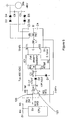
- the modification of Figure 5 is the inclusion of a resistor R6, in the form of two 1M ⁇ resistors in series, from the voltage source line to the operational amplifier input 123 to which the feed back resistor R5 is connected.
- the resistors R6-R5 form a voltage divider.
- the divider is such that the voltage across the resistor R5 is substantially the same as the voltage across the current measuring resistor, typically both of the order of 100mV, giving 200mV at the operational amplifier input.
- the actual voltage varies with both the actual current in the converter and the actual voltage on the voltage source line. It will be appreciated that an increase in the operational amplifier input of 200mV due to increase in the voltage source line will be equivalent to an increase in the operational amplifier input 200mV due to increase in the current. Both raise the integrated output voltage of the operational amplifier, with the result that the controlled current is reduced.
- R6 is seven orders of magnitude greater than R1 and R5 is four orders of magnitude greater, any change in U which create an appreciable change of voltage at the operational amplifier input is unlikely to cause an appreciable change of voltage across R1, whose voltage is controlled only by the current through it. Accordingly the voltage across R1 is added to that across R5 and the sum is input to the operational amplifier.
Landscapes
- Engineering & Computer Science (AREA)
- Power Engineering (AREA)
- Physics & Mathematics (AREA)
- Electromagnetism (AREA)
- Control Of High-Frequency Heating Circuits (AREA)
- Microwave Tubes (AREA)
- Dc-Dc Converters (AREA)
Claims (14)
- Stromversorgung für ein Magnetron, mit:• einer Gleichstrom-Spannungsquelle;• einem Konverter (101) zum Anheben der Ausgangsspannung der Gleichstrom-Spannungsquelle, wobei der Konverter aufweist:• einen kapazitativ-induktiven Resonanzkreis (L1, C3, C4),• einen Schaltkreis (IC1, T1, T2), der zum Betreiben des Resonanzkreises mit einer veränderlichen Frequenz ausgestaltet ist, die mittels eines Regelsignaleingangs gesteuert oder geregelt wird, um eine Wechselspannung bereit zu stellen,• einen Transformator (TR1), der mit dem Resonanzkreis verbunden ist, um die Wechselspannung anzuheben,• einen Gleichrichter (107) zum Geichrichten der angehobenen Wechselspannung zu einer angehobenen Gleichstromspannung zur Beaufschlagung des Magnetrons;• Mitteln (109) zum Messen des Stroms von der Gleichstromspannungsquelle, der durch den Konverter fließt;• einem Mikroprozessor (103), der programmiert ist, um ein Kontrollsignal zu erzeugen, das indikativ ist für eine gewünschte Ausgangsleistung des Magnetrons; und• einem integrierten Schaltkreis (122), der ausgebildet ist, ein Kontrollsignal an den Konverterschaltkreis anzulegen:dadurch gekennzeichnet, dass:• die veränderliche Frequenz, bei der der Schaltkreis angepasst ist, den Resonanzkreis zu betreiben, oberhalb der Resonanzfrequenz des Resonanzkreises liegt und• der integrierte Schaltkreis (122) in einer Rückkopplungsschleife angeordnet ist, wodurch er geeignet ist, ein Kontrollsignal am Konverterschaltkreis entsprechend einem Vergleich eines Signals von den Strommessmitteln mit dem Signal von dem Mikroprozessor aufzuschalten zum Steuern oder Regeln der Leistung des Magnetrons auf einen Leistungssollwert.
- Stromversorgung nach Anspruch 1, dadurch gekennzeichnet, dass der integrierte Schaltkreis eine analoge Vorrichtung ist.
- Stromversorgung nach Anspruch 2, dadurch gekennzeichnet, dass der integrierte Schaltkreis ein Operationsverstärker ist, der als Fehlersignalverstärker angeschlossen ist, wobei das Fehlersignal die Differenz zwischen Signalen ist, die eine Messung des Konverterstroms und der Soll-Ausgangsleistung des Magnetrons angeben.
- Stromversorgung nach Anspruch 1, Anspruch 2 oder Anspruch 3, dadurch gekennzeichnet, dass der integrierte Schaltkreis als Integrationsschaltung mit einem Resonanzkondensatorausgebildet ist, wodurch seine Ausgangsspannung angepasst ist, um eine Spannungs-Frequenz-Schaltung zum Steuern oder Regeln des Konverters zu kontrollieren.
- Stromversorgung nach einem der vorstehenden Ansprüche, dadurch gekennzeichnet, dass die integrierte Schaltung ausgestaltet und angeordnet ist für den Vergleich unmittelbar zwischen dem gemessenen Stromsignal und dem gewünschten Leistungssignal, wobei die integrierte Schaltung so angeschlossen ist, dass sie ausschließlich diese Signale empfängt, so dass der Konverterstrom in Übereinstimmung mit der gewünschten Leistung unabhängig von in stationären Veränderungen in der Spannung der Gleichstrom-Spannungsquelle kontrolliert wird.
- Stromversorgung nach Anspruch 5, dadurch gekennzeichnet, dass die Strommessmittel einen in Reihe mit dem Konverter geschalteten Widerstand aufweisen, wobei ein Anschluss des Widerstands geerdet ist und der andere an einem Eingang der integrierten Schaltung angeschlossen ist, vorzugsweise über einen Regelwiderstand.
- Stromversorgung nach einem der Ansprüche 1 bis 4, dadurch gekennzeichnet, dass die integrierte Schaltung ausgestaltet und angeordnet ist für den Vergleich nicht nur zwischen dem gemessenen Stromsignal und dem gewünschten Leistungssignal, sondern auch vorübergehende Schwankungen in der Spannung der Gleichstromspannungsquelle berücksichtigt, ein Signal, das ein Maß für die Spannung der Spannungsquelle darstellt, ebenfalls in die integrierte Schaltung eingespeist wird, so dass der Konverterstrom derart gesteuert oder geregelt wird, dass die durch den Konverter gehende Leistung im Hinblick auf die gewünschte Leistung gesteuert oder geregelt wird.
- Stromversorgung nach Anspruch 4, dadurch gekennzeichnet:• die Strommessmittel ein in Reihe mit dem Konverter geschalteter Widerstand sind, wobei ein Anschluss des Widerstands geerdet ist und• ein Potentialteiler für einen Eingang zur integrierten Schaltung vorgesehen ist, wobei der Teiler zwei Trennwiderstände zwischen einer Ausgangsschiene der Gleichstrom-Spannungsquelle und dem nicht geerdeten Anschluss des Strommesswiderstands aufweist, wobei der gemeinsame Anschluss der zwei Trennwiderstände an einem Eingang der integrierten Schaltung angeschlossen ist.
- Stromversorgung nach Anspruch 8, dadurch gekennzeichnet, dass• die Strommessmittel ein mit dem Konverter in Reihe geschalteter Widerstand sind, wobei ein Anschluss des Widerstands geerdet ist und• weiter vorgesehen ist:• ein Potentialteiler mit zwei Trennwiderständen zwischen einer Ausgangsschiene der Gleichstrom-Spannungsquelle und einer Null-Volt-Schiene, und• eine Verstärkungsschaltung, wobei die Spannung an dem Strommesswiderstand an einem Verstärkungseingang und die Spannung an dem gemeinsamen Anschluss der Trennwiderstände an einem anderen Verstärkungseingang anliegt und der Verstärkungsausgang auf die integrierte Schaltung aufgeschaltet ist zum Vergleich mit dem Mikroprozessorausgang.
- Stromversorgung nach einem der vorstehenden Ansprüche, dadurch gekennzeichnet, dass der Mikroprozessor programmiert ist, um Rauschen von dem gewünschten Konverterstromsignal herauszufiltern.
- Stromversorgung nach einem der Ansprüche 1 bis 9, gekennzeichnet durch eine Filterschaltung, die zwischen dem Mikroprozessor und dem Operationsverstärker vorgesehen ist.
- Stromversorgung nach einem der vorstehenden Ansprüche, dadurch gekennzeichnet, dass der Schaltstromkreis ausgebildet ist, um die Frequenz des Konverters in Abhängigkeit von einem veränderlichen Spannungsausgangssignal des Operationsverstärkers zu steuern oder zu regeln, derart, dass ein Anstieg der Frequenz mit einer Verringerung der Magnetronantriebsleistung und des Mikrowellen-Outputs korrespondiert.
- Stromversorgung nach einem dervorstehenden Ansprüche, dadurch gekennzeichnet, dass der Schaltstromkreis ausgebildet ist, um den Auslastungsgrad des Konverters in Abhängigkeit vom Ausgang der integrierten Schaltung zu steuern oder zu regeln, wobei eine Verringerung des Auslastungsgrads mit einer Verringerung der Magnetron-Antriebsspannung und des Mikrowellen-Outputs korrespondiert und vorzugsweise der Schaltstromkreis von einer Uhr in dem Mikroprozessor zeitgesteuert ist oder der Schaltstromkreis einen eigenen Oszillator hat.
- Stromversorgung nach einem der vorstehenden Ansprüche, dadurch gekennzeichnet, dass der Konverter eine Null-Spannungs-Schaltvorrichtung oder eine Null-Strom-Schaltvorrichtung ist.
Priority Applications (1)
| Application Number | Priority Date | Filing Date | Title |
|---|---|---|---|
| PL11741675T PL2583534T3 (pl) | 2010-06-21 | 2011-06-17 | Zasilacz magnetronowy |
Applications Claiming Priority (2)
| Application Number | Priority Date | Filing Date | Title |
|---|---|---|---|
| GBGB1010358.8A GB201010358D0 (en) | 2010-06-21 | 2010-06-21 | Light source |
| PCT/GB2011/000920 WO2011161401A1 (en) | 2010-06-21 | 2011-06-17 | Magnetron power supply |
Publications (2)
| Publication Number | Publication Date |
|---|---|
| EP2583534A1 EP2583534A1 (de) | 2013-04-24 |
| EP2583534B1 true EP2583534B1 (de) | 2014-07-30 |
Family
ID=42582709
Family Applications (1)
| Application Number | Title | Priority Date | Filing Date |
|---|---|---|---|
| EP11741675.0A Not-in-force EP2583534B1 (de) | 2010-06-21 | 2011-06-17 | Stromversorgung für ein magnetron |
Country Status (12)
| Country | Link |
|---|---|
| US (1) | US10038386B2 (de) |
| EP (1) | EP2583534B1 (de) |
| JP (1) | JP5809259B2 (de) |
| KR (1) | KR20130116236A (de) |
| AU (1) | AU2011268754B2 (de) |
| BR (1) | BR112012032759A2 (de) |
| CA (1) | CA2803333A1 (de) |
| DK (1) | DK2583534T3 (de) |
| ES (1) | ES2513590T3 (de) |
| GB (1) | GB201010358D0 (de) |
| PL (1) | PL2583534T3 (de) |
| WO (1) | WO2011161401A1 (de) |
Families Citing this family (3)
| Publication number | Priority date | Publication date | Assignee | Title |
|---|---|---|---|---|
| CN107005169B (zh) * | 2014-12-08 | 2020-01-31 | B/E航空公司 | 准谐振磁控管电力供应器 |
| CN111884604B (zh) * | 2020-08-07 | 2024-04-09 | 安徽华东光电技术研究所有限公司 | 一种大功率微波固态功放供电及保护电路 |
| TWI844088B (zh) * | 2022-09-02 | 2024-06-01 | 宏碁股份有限公司 | 具諧振穩壓回授補償設計之電源供應器 |
Family Cites Families (15)
| Publication number | Priority date | Publication date | Assignee | Title |
|---|---|---|---|---|
| US4680506A (en) * | 1984-12-10 | 1987-07-14 | Nilssen Ole K | Inverter-type microwave oven power supply |
| US4956581A (en) * | 1985-12-12 | 1990-09-11 | Nilssen Ole K | Flyback converter microwave oven power supply |
| US4882663A (en) * | 1985-12-23 | 1989-11-21 | Nilssen Ole K | MOSFET flyback converter |
| US4873408A (en) | 1987-12-28 | 1989-10-10 | General Electric Company | Magnetron with microprocessor based feedback control |
| US4939632A (en) | 1989-02-14 | 1990-07-03 | U.S. Philips Corporation | Power supply circuit |
| JP2691626B2 (ja) * | 1990-01-16 | 1997-12-17 | 株式会社ユタカ電機製作所 | 高周波加熱装置用スイッチング電源 |
| KR920003586Y1 (ko) * | 1990-04-14 | 1992-05-30 | 주식회사 금성사 | 마그네트론 구동 전원회로 |
| US5636106A (en) * | 1994-01-10 | 1997-06-03 | University Of Central Florida | Variable frequency controlled zero-voltage switching single-ended current-fed DC-to-AC converter with output isolation |
| US5642268A (en) * | 1995-10-30 | 1997-06-24 | Xerox Corporation | Power supply for a magnetron having controlled output power and narrow bandwidth |
| JP3477085B2 (ja) * | 1998-10-05 | 2003-12-10 | 株式会社東芝 | 高周波加熱装置用インバータ電源 |
| GB2348496A (en) * | 1999-03-31 | 2000-10-04 | Frazer Nash Consultancy Ltd | Method and apparatus for the detection of scratching and similar surface action to glass |
| JP4978062B2 (ja) * | 2006-06-02 | 2012-07-18 | パナソニック株式会社 | 高周波誘電加熱用電力制御装置およびその制御方法 |
| MY152374A (en) | 2007-11-16 | 2014-09-15 | Ceravision Ltd | Light source |
| JP2009177954A (ja) * | 2008-01-24 | 2009-08-06 | Sanken Electric Co Ltd | 力率改善コンバータ |
| GB201011789D0 (en) | 2010-07-13 | 2010-08-25 | Ceravision Ltd | Magnetron power supply |
-
2010
- 2010-06-21 GB GBGB1010358.8A patent/GB201010358D0/en not_active Ceased
-
2011
- 2011-06-17 PL PL11741675T patent/PL2583534T3/pl unknown
- 2011-06-17 WO PCT/GB2011/000920 patent/WO2011161401A1/en not_active Ceased
- 2011-06-17 US US13/806,433 patent/US10038386B2/en not_active Expired - Fee Related
- 2011-06-17 JP JP2013515951A patent/JP5809259B2/ja not_active Expired - Fee Related
- 2011-06-17 ES ES11741675.0T patent/ES2513590T3/es active Active
- 2011-06-17 KR KR1020137000655A patent/KR20130116236A/ko not_active Ceased
- 2011-06-17 BR BR112012032759A patent/BR112012032759A2/pt not_active IP Right Cessation
- 2011-06-17 CA CA2803333A patent/CA2803333A1/en not_active Abandoned
- 2011-06-17 EP EP11741675.0A patent/EP2583534B1/de not_active Not-in-force
- 2011-06-17 AU AU2011268754A patent/AU2011268754B2/en not_active Ceased
- 2011-06-17 DK DK11741675.0T patent/DK2583534T3/da active
Also Published As
| Publication number | Publication date |
|---|---|
| JP5809259B2 (ja) | 2015-11-10 |
| DK2583534T3 (da) | 2014-10-27 |
| EP2583534A1 (de) | 2013-04-24 |
| JP2013529886A (ja) | 2013-07-22 |
| KR20130116236A (ko) | 2013-10-23 |
| AU2011268754B2 (en) | 2014-11-06 |
| US10038386B2 (en) | 2018-07-31 |
| RU2013102265A (ru) | 2014-07-27 |
| GB201010358D0 (en) | 2010-08-04 |
| ES2513590T3 (es) | 2014-10-27 |
| BR112012032759A2 (pt) | 2016-11-08 |
| PL2583534T3 (pl) | 2015-02-27 |
| US20130100709A1 (en) | 2013-04-25 |
| CA2803333A1 (en) | 2011-12-29 |
| WO2011161401A1 (en) | 2011-12-29 |
| AU2011268754A1 (en) | 2013-01-10 |
| CN103026784A (zh) | 2013-04-03 |
Similar Documents
| Publication | Publication Date | Title |
|---|---|---|
| US9706612B2 (en) | Method and circuit for controlling an LED load | |
| US9084303B2 (en) | Device and method for driving LEDs | |
| JP3216572B2 (ja) | 圧電トランスの駆動回路 | |
| TWI388960B (zh) | 電源系統、顯示系統及對負載供電之方法 | |
| CN102396295B (zh) | 借助于led电流平均值和双向计数器的led的功率调节 | |
| EP2432105B1 (de) | Stromresonanzumrichter zur Leistungsfaktorkorrektur | |
| US20100207536A1 (en) | High efficiency light source with integrated ballast | |
| EP2583534B1 (de) | Stromversorgung für ein magnetron | |
| US20070019446A1 (en) | Pfc pre-regulator frequency dithering circuit | |
| EP2594110B1 (de) | Stromversorgung für ein magnetron | |
| EP0785611A2 (de) | Stromversorgungsvorrichtung | |
| CN103026784B (zh) | 磁控管电源 | |
| JP7199014B2 (ja) | 照明手段アセンブリの作動装置および作動方法 | |
| HK1178020A (en) | Magnetron power supply | |
| EP1879285B1 (de) | Eine Halbbrücke verwendende Stromversorgung | |
| RU2575166C2 (ru) | Источник питания магнетрона | |
| TW201318482A (zh) | 磁控管電源供應器 | |
| EP2208399B1 (de) | Betrieb eines beleuchtungsmittels | |
| TWI565368B (zh) | 磁控管電源供應器 | |
| JP3029422B2 (ja) | 電源装置 | |
| CN101861041B (zh) | 驱动至少两种不同类型的放电灯的电子镇流器 | |
| HK1186335B (en) | Magnetron power supply | |
| JPH09298095A (ja) | 放電ランプ点灯装置及び照明装置 | |
| JPH04133292A (ja) | 放電灯点灯装置 |
Legal Events
| Date | Code | Title | Description |
|---|---|---|---|
| PUAI | Public reference made under article 153(3) epc to a published international application that has entered the european phase |
Free format text: ORIGINAL CODE: 0009012 |
|
| 17P | Request for examination filed |
Effective date: 20121219 |
|
| AK | Designated contracting states |
Kind code of ref document: A1 Designated state(s): AL AT BE BG CH CY CZ DE DK EE ES FI FR GB GR HR HU IE IS IT LI LT LU LV MC MK MT NL NO PL PT RO RS SE SI SK SM TR |
|
| DAX | Request for extension of the european patent (deleted) | ||
| GRAP | Despatch of communication of intention to grant a patent |
Free format text: ORIGINAL CODE: EPIDOSNIGR1 |
|
| INTG | Intention to grant announced |
Effective date: 20140109 |
|
| GRAS | Grant fee paid |
Free format text: ORIGINAL CODE: EPIDOSNIGR3 |
|
| GRAA | (expected) grant |
Free format text: ORIGINAL CODE: 0009210 |
|
| AK | Designated contracting states |
Kind code of ref document: B1 Designated state(s): AL AT BE BG CH CY CZ DE DK EE ES FI FR GB GR HR HU IE IS IT LI LT LU LV MC MK MT NL NO PL PT RO RS SE SI SK SM TR |
|
| REG | Reference to a national code |
Ref country code: GB Ref legal event code: FG4D |
|
| REG | Reference to a national code |
Ref country code: CH Ref legal event code: EP |
|
| REG | Reference to a national code |
Ref country code: AT Ref legal event code: REF Ref document number: 680495 Country of ref document: AT Kind code of ref document: T Effective date: 20140815 |
|
| REG | Reference to a national code |
Ref country code: IE Ref legal event code: FG4D |
|
| REG | Reference to a national code |
Ref country code: DE Ref legal event code: R096 Ref document number: 602011008763 Country of ref document: DE Effective date: 20140911 |
|
| REG | Reference to a national code |
Ref country code: DK Ref legal event code: T3 Effective date: 20141021 Ref country code: ES Ref legal event code: FG2A Ref document number: 2513590 Country of ref document: ES Kind code of ref document: T3 Effective date: 20141027 |
|
| REG | Reference to a national code |
Ref country code: CH Ref legal event code: NV Representative=s name: SCHMAUDER AND PARTNER AG PATENT- UND MARKENANW, CH |
|
| REG | Reference to a national code |
Ref country code: SE Ref legal event code: TRGR |
|
| REG | Reference to a national code |
Ref country code: NL Ref legal event code: T3 |
|
| REG | Reference to a national code |
Ref country code: AT Ref legal event code: MK05 Ref document number: 680495 Country of ref document: AT Kind code of ref document: T Effective date: 20140730 |
|
| REG | Reference to a national code |
Ref country code: LT Ref legal event code: MG4D |
|
| PG25 | Lapsed in a contracting state [announced via postgrant information from national office to epo] |
Ref country code: NO Free format text: LAPSE BECAUSE OF FAILURE TO SUBMIT A TRANSLATION OF THE DESCRIPTION OR TO PAY THE FEE WITHIN THE PRESCRIBED TIME-LIMIT Effective date: 20141030 Ref country code: FI Free format text: LAPSE BECAUSE OF FAILURE TO SUBMIT A TRANSLATION OF THE DESCRIPTION OR TO PAY THE FEE WITHIN THE PRESCRIBED TIME-LIMIT Effective date: 20140730 Ref country code: LT Free format text: LAPSE BECAUSE OF FAILURE TO SUBMIT A TRANSLATION OF THE DESCRIPTION OR TO PAY THE FEE WITHIN THE PRESCRIBED TIME-LIMIT Effective date: 20140730 Ref country code: PT Free format text: LAPSE BECAUSE OF FAILURE TO SUBMIT A TRANSLATION OF THE DESCRIPTION OR TO PAY THE FEE WITHIN THE PRESCRIBED TIME-LIMIT Effective date: 20141202 Ref country code: GR Free format text: LAPSE BECAUSE OF FAILURE TO SUBMIT A TRANSLATION OF THE DESCRIPTION OR TO PAY THE FEE WITHIN THE PRESCRIBED TIME-LIMIT Effective date: 20141031 Ref country code: BG Free format text: LAPSE BECAUSE OF FAILURE TO SUBMIT A TRANSLATION OF THE DESCRIPTION OR TO PAY THE FEE WITHIN THE PRESCRIBED TIME-LIMIT Effective date: 20141030 |
|
| PG25 | Lapsed in a contracting state [announced via postgrant information from national office to epo] |
Ref country code: AT Free format text: LAPSE BECAUSE OF FAILURE TO SUBMIT A TRANSLATION OF THE DESCRIPTION OR TO PAY THE FEE WITHIN THE PRESCRIBED TIME-LIMIT Effective date: 20140730 Ref country code: HR Free format text: LAPSE BECAUSE OF FAILURE TO SUBMIT A TRANSLATION OF THE DESCRIPTION OR TO PAY THE FEE WITHIN THE PRESCRIBED TIME-LIMIT Effective date: 20140730 Ref country code: LV Free format text: LAPSE BECAUSE OF FAILURE TO SUBMIT A TRANSLATION OF THE DESCRIPTION OR TO PAY THE FEE WITHIN THE PRESCRIBED TIME-LIMIT Effective date: 20140730 Ref country code: IS Free format text: LAPSE BECAUSE OF FAILURE TO SUBMIT A TRANSLATION OF THE DESCRIPTION OR TO PAY THE FEE WITHIN THE PRESCRIBED TIME-LIMIT Effective date: 20141130 Ref country code: RS Free format text: LAPSE BECAUSE OF FAILURE TO SUBMIT A TRANSLATION OF THE DESCRIPTION OR TO PAY THE FEE WITHIN THE PRESCRIBED TIME-LIMIT Effective date: 20140730 Ref country code: CY Free format text: LAPSE BECAUSE OF FAILURE TO SUBMIT A TRANSLATION OF THE DESCRIPTION OR TO PAY THE FEE WITHIN THE PRESCRIBED TIME-LIMIT Effective date: 20140730 |
|
| REG | Reference to a national code |
Ref country code: PL Ref legal event code: T3 |
|
| PG25 | Lapsed in a contracting state [announced via postgrant information from national office to epo] |
Ref country code: CZ Free format text: LAPSE BECAUSE OF FAILURE TO SUBMIT A TRANSLATION OF THE DESCRIPTION OR TO PAY THE FEE WITHIN THE PRESCRIBED TIME-LIMIT Effective date: 20140730 Ref country code: RO Free format text: LAPSE BECAUSE OF FAILURE TO SUBMIT A TRANSLATION OF THE DESCRIPTION OR TO PAY THE FEE WITHIN THE PRESCRIBED TIME-LIMIT Effective date: 20140730 Ref country code: SK Free format text: LAPSE BECAUSE OF FAILURE TO SUBMIT A TRANSLATION OF THE DESCRIPTION OR TO PAY THE FEE WITHIN THE PRESCRIBED TIME-LIMIT Effective date: 20140730 Ref country code: EE Free format text: LAPSE BECAUSE OF FAILURE TO SUBMIT A TRANSLATION OF THE DESCRIPTION OR TO PAY THE FEE WITHIN THE PRESCRIBED TIME-LIMIT Effective date: 20140730 |
|
| REG | Reference to a national code |
Ref country code: DE Ref legal event code: R097 Ref document number: 602011008763 Country of ref document: DE |
|
| PLBE | No opposition filed within time limit |
Free format text: ORIGINAL CODE: 0009261 |
|
| STAA | Information on the status of an ep patent application or granted ep patent |
Free format text: STATUS: NO OPPOSITION FILED WITHIN TIME LIMIT |
|
| 26N | No opposition filed |
Effective date: 20150504 |
|
| PGFP | Annual fee paid to national office [announced via postgrant information from national office to epo] |
Ref country code: DK Payment date: 20150619 Year of fee payment: 5 Ref country code: SE Payment date: 20150616 Year of fee payment: 5 Ref country code: CH Payment date: 20150618 Year of fee payment: 5 Ref country code: ES Payment date: 20150618 Year of fee payment: 5 |
|
| PGFP | Annual fee paid to national office [announced via postgrant information from national office to epo] |
Ref country code: PL Payment date: 20150617 Year of fee payment: 5 Ref country code: NL Payment date: 20150618 Year of fee payment: 5 |
|
| PG25 | Lapsed in a contracting state [announced via postgrant information from national office to epo] |
Ref country code: SI Free format text: LAPSE BECAUSE OF FAILURE TO SUBMIT A TRANSLATION OF THE DESCRIPTION OR TO PAY THE FEE WITHIN THE PRESCRIBED TIME-LIMIT Effective date: 20140730 |
|
| PGFP | Annual fee paid to national office [announced via postgrant information from national office to epo] |
Ref country code: IT Payment date: 20150629 Year of fee payment: 5 |
|
| PG25 | Lapsed in a contracting state [announced via postgrant information from national office to epo] |
Ref country code: MC Free format text: LAPSE BECAUSE OF FAILURE TO SUBMIT A TRANSLATION OF THE DESCRIPTION OR TO PAY THE FEE WITHIN THE PRESCRIBED TIME-LIMIT Effective date: 20140730 |
|
| PG25 | Lapsed in a contracting state [announced via postgrant information from national office to epo] |
Ref country code: LU Free format text: LAPSE BECAUSE OF FAILURE TO SUBMIT A TRANSLATION OF THE DESCRIPTION OR TO PAY THE FEE WITHIN THE PRESCRIBED TIME-LIMIT Effective date: 20150617 |
|
| REG | Reference to a national code |
Ref country code: IE Ref legal event code: MM4A |
|
| PG25 | Lapsed in a contracting state [announced via postgrant information from national office to epo] |
Ref country code: IE Free format text: LAPSE BECAUSE OF NON-PAYMENT OF DUE FEES Effective date: 20150617 |
|
| PG25 | Lapsed in a contracting state [announced via postgrant information from national office to epo] |
Ref country code: BE Free format text: LAPSE BECAUSE OF FAILURE TO SUBMIT A TRANSLATION OF THE DESCRIPTION OR TO PAY THE FEE WITHIN THE PRESCRIBED TIME-LIMIT Effective date: 20140730 |
|
| REG | Reference to a national code |
Ref country code: FR Ref legal event code: PLFP Year of fee payment: 6 |
|
| PG25 | Lapsed in a contracting state [announced via postgrant information from national office to epo] |
Ref country code: MT Free format text: LAPSE BECAUSE OF FAILURE TO SUBMIT A TRANSLATION OF THE DESCRIPTION OR TO PAY THE FEE WITHIN THE PRESCRIBED TIME-LIMIT Effective date: 20140730 |
|
| REG | Reference to a national code |
Ref country code: DK Ref legal event code: EBP Effective date: 20160630 |
|
| REG | Reference to a national code |
Ref country code: SE Ref legal event code: EUG Ref country code: CH Ref legal event code: PL |
|
| REG | Reference to a national code |
Ref country code: NL Ref legal event code: MM Effective date: 20160701 |
|
| PG25 | Lapsed in a contracting state [announced via postgrant information from national office to epo] |
Ref country code: SE Free format text: LAPSE BECAUSE OF NON-PAYMENT OF DUE FEES Effective date: 20160618 |
|
| PG25 | Lapsed in a contracting state [announced via postgrant information from national office to epo] |
Ref country code: LI Free format text: LAPSE BECAUSE OF NON-PAYMENT OF DUE FEES Effective date: 20160630 Ref country code: CH Free format text: LAPSE BECAUSE OF NON-PAYMENT OF DUE FEES Effective date: 20160630 |
|
| PG25 | Lapsed in a contracting state [announced via postgrant information from national office to epo] |
Ref country code: HU Free format text: LAPSE BECAUSE OF FAILURE TO SUBMIT A TRANSLATION OF THE DESCRIPTION OR TO PAY THE FEE WITHIN THE PRESCRIBED TIME-LIMIT; INVALID AB INITIO Effective date: 20110617 Ref country code: NL Free format text: LAPSE BECAUSE OF NON-PAYMENT OF DUE FEES Effective date: 20160701 Ref country code: SM Free format text: LAPSE BECAUSE OF FAILURE TO SUBMIT A TRANSLATION OF THE DESCRIPTION OR TO PAY THE FEE WITHIN THE PRESCRIBED TIME-LIMIT Effective date: 20140730 |
|
| PG25 | Lapsed in a contracting state [announced via postgrant information from national office to epo] |
Ref country code: IT Free format text: LAPSE BECAUSE OF NON-PAYMENT OF DUE FEES Effective date: 20160617 |
|
| PG25 | Lapsed in a contracting state [announced via postgrant information from national office to epo] |
Ref country code: DK Free format text: LAPSE BECAUSE OF NON-PAYMENT OF DUE FEES Effective date: 20160630 |
|
| PG25 | Lapsed in a contracting state [announced via postgrant information from national office to epo] |
Ref country code: TR Free format text: LAPSE BECAUSE OF FAILURE TO SUBMIT A TRANSLATION OF THE DESCRIPTION OR TO PAY THE FEE WITHIN THE PRESCRIBED TIME-LIMIT Effective date: 20140730 |
|
| REG | Reference to a national code |
Ref country code: FR Ref legal event code: PLFP Year of fee payment: 7 |
|
| PG25 | Lapsed in a contracting state [announced via postgrant information from national office to epo] |
Ref country code: PL Free format text: LAPSE BECAUSE OF NON-PAYMENT OF DUE FEES Effective date: 20160617 |
|
| REG | Reference to a national code |
Ref country code: FR Ref legal event code: ST Effective date: 20180228 |
|
| PG25 | Lapsed in a contracting state [announced via postgrant information from national office to epo] |
Ref country code: ES Free format text: LAPSE BECAUSE OF NON-PAYMENT OF DUE FEES Effective date: 20160618 Ref country code: FR Free format text: LAPSE BECAUSE OF NON-PAYMENT OF DUE FEES Effective date: 20170630 |
|
| PG25 | Lapsed in a contracting state [announced via postgrant information from national office to epo] |
Ref country code: MK Free format text: LAPSE BECAUSE OF FAILURE TO SUBMIT A TRANSLATION OF THE DESCRIPTION OR TO PAY THE FEE WITHIN THE PRESCRIBED TIME-LIMIT Effective date: 20140730 |
|
| REG | Reference to a national code |
Ref country code: FR Ref legal event code: RN Effective date: 20180717 |
|
| REG | Reference to a national code |
Ref country code: FR Ref legal event code: FC Effective date: 20180724 |
|
| REG | Reference to a national code |
Ref country code: FR Ref legal event code: PLFP Year of fee payment: 8 |
|
| REG | Reference to a national code |
Ref country code: FR Ref legal event code: PLFP Year of fee payment: 9 |
|
| PG25 | Lapsed in a contracting state [announced via postgrant information from national office to epo] |
Ref country code: FR Free format text: LAPSE BECAUSE OF NON-PAYMENT OF DUE FEES Effective date: 20170630 Ref country code: AL Free format text: LAPSE BECAUSE OF FAILURE TO SUBMIT A TRANSLATION OF THE DESCRIPTION OR TO PAY THE FEE WITHIN THE PRESCRIBED TIME-LIMIT Effective date: 20140730 |
|
| PGFP | Annual fee paid to national office [announced via postgrant information from national office to epo] |
Ref country code: FR Payment date: 20180910 Year of fee payment: 9 Ref country code: DE Payment date: 20180702 Year of fee payment: 8 Ref country code: GB Payment date: 20180629 Year of fee payment: 8 |
|
| PGRI | Patent reinstated in contracting state [announced from national office to epo] |
Ref country code: FR Effective date: 20180724 |
|
| REG | Reference to a national code |
Ref country code: ES Ref legal event code: FD2A Effective date: 20181112 |
|
| REG | Reference to a national code |
Ref country code: DE Ref legal event code: R119 Ref document number: 602011008763 Country of ref document: DE |
|
| GBPC | Gb: european patent ceased through non-payment of renewal fee |
Effective date: 20190617 |
|
| REG | Reference to a national code |
Ref country code: GB Ref legal event code: 732E Free format text: REGISTERED BETWEEN 20200227 AND 20200304 |
|
| PG25 | Lapsed in a contracting state [announced via postgrant information from national office to epo] |
Ref country code: DE Free format text: LAPSE BECAUSE OF NON-PAYMENT OF DUE FEES Effective date: 20200101 Ref country code: GB Free format text: LAPSE BECAUSE OF NON-PAYMENT OF DUE FEES Effective date: 20190617 |
|
| PG25 | Lapsed in a contracting state [announced via postgrant information from national office to epo] |
Ref country code: FR Free format text: LAPSE BECAUSE OF NON-PAYMENT OF DUE FEES Effective date: 20200630 |