EP2583141B1 - Optisches beleuchtungssystem für mikrolithografie und projektionsbeleichtungssystem mit einem derartigen optischen beleuchtungssystem - Google Patents
Optisches beleuchtungssystem für mikrolithografie und projektionsbeleichtungssystem mit einem derartigen optischen beleuchtungssystem Download PDFInfo
- Publication number
- EP2583141B1 EP2583141B1 EP11723967.3A EP11723967A EP2583141B1 EP 2583141 B1 EP2583141 B1 EP 2583141B1 EP 11723967 A EP11723967 A EP 11723967A EP 2583141 B1 EP2583141 B1 EP 2583141B1
- Authority
- EP
- European Patent Office
- Prior art keywords
- raster
- illumination
- illumination light
- angle
- light part
- Prior art date
- Legal status (The legal status is an assumption and is not a legal conclusion. Google has not performed a legal analysis and makes no representation as to the accuracy of the status listed.)
- Active
Links
- 238000005286 illumination Methods 0.000 title claims description 282
- 230000003287 optical effect Effects 0.000 title claims description 59
- 238000001393 microlithography Methods 0.000 title claims description 8
- 238000009826 distribution Methods 0.000 claims description 67
- 210000001747 pupil Anatomy 0.000 claims description 21
- 230000001419 dependent effect Effects 0.000 claims description 8
- 238000004519 manufacturing process Methods 0.000 claims description 7
- 238000000034 method Methods 0.000 claims description 7
- 238000003384 imaging method Methods 0.000 claims description 3
- 239000000463 material Substances 0.000 claims description 2
- 239000000758 substrate Substances 0.000 claims description 2
- 230000003213 activating effect Effects 0.000 claims 2
- 230000000694 effects Effects 0.000 description 22
- 230000000875 corresponding effect Effects 0.000 description 12
- IYLGZMTXKJYONK-ACLXAEORSA-N (12s,15r)-15-hydroxy-11,16-dioxo-15,20-dihydrosenecionan-12-yl acetate Chemical compound O1C(=O)[C@](CC)(O)C[C@@H](C)[C@](C)(OC(C)=O)C(=O)OCC2=CCN3[C@H]2[C@H]1CC3 IYLGZMTXKJYONK-ACLXAEORSA-N 0.000 description 10
- 239000003990 capacitor Substances 0.000 description 10
- 210000000887 face Anatomy 0.000 description 10
- IYLGZMTXKJYONK-UHFFFAOYSA-N ruwenine Natural products O1C(=O)C(CC)(O)CC(C)C(C)(OC(C)=O)C(=O)OCC2=CCN3C2C1CC3 IYLGZMTXKJYONK-UHFFFAOYSA-N 0.000 description 10
- 241000264877 Hippospongia communis Species 0.000 description 5
- 230000002596 correlated effect Effects 0.000 description 4
- 238000006243 chemical reaction Methods 0.000 description 3
- 238000006073 displacement reaction Methods 0.000 description 3
- 230000004075 alteration Effects 0.000 description 1
- 238000010276 construction Methods 0.000 description 1
- 238000001459 lithography Methods 0.000 description 1
- 239000004065 semiconductor Substances 0.000 description 1
- 239000013589 supplement Substances 0.000 description 1
- 230000007704 transition Effects 0.000 description 1
Images


Classifications
-
- G—PHYSICS
- G03—PHOTOGRAPHY; CINEMATOGRAPHY; ANALOGOUS TECHNIQUES USING WAVES OTHER THAN OPTICAL WAVES; ELECTROGRAPHY; HOLOGRAPHY
- G03F—PHOTOMECHANICAL PRODUCTION OF TEXTURED OR PATTERNED SURFACES, e.g. FOR PRINTING, FOR PROCESSING OF SEMICONDUCTOR DEVICES; MATERIALS THEREFOR; ORIGINALS THEREFOR; APPARATUS SPECIALLY ADAPTED THEREFOR
- G03F7/00—Photomechanical, e.g. photolithographic, production of textured or patterned surfaces, e.g. printing surfaces; Materials therefor, e.g. comprising photoresists; Apparatus specially adapted therefor
- G03F7/70—Microphotolithographic exposure; Apparatus therefor
- G03F7/70058—Mask illumination systems
- G03F7/70091—Illumination settings, i.e. intensity distribution in the pupil plane or angular distribution in the field plane; On-axis or off-axis settings, e.g. annular, dipole or quadrupole settings; Partial coherence control, i.e. sigma or numerical aperture [NA]
-
- G—PHYSICS
- G03—PHOTOGRAPHY; CINEMATOGRAPHY; ANALOGOUS TECHNIQUES USING WAVES OTHER THAN OPTICAL WAVES; ELECTROGRAPHY; HOLOGRAPHY
- G03F—PHOTOMECHANICAL PRODUCTION OF TEXTURED OR PATTERNED SURFACES, e.g. FOR PRINTING, FOR PROCESSING OF SEMICONDUCTOR DEVICES; MATERIALS THEREFOR; ORIGINALS THEREFOR; APPARATUS SPECIALLY ADAPTED THEREFOR
- G03F7/00—Photomechanical, e.g. photolithographic, production of textured or patterned surfaces, e.g. printing surfaces; Materials therefor, e.g. comprising photoresists; Apparatus specially adapted therefor
- G03F7/70—Microphotolithographic exposure; Apparatus therefor
- G03F7/70058—Mask illumination systems
- G03F7/70075—Homogenization of illumination intensity in the mask plane by using an integrator, e.g. fly's eye lens, facet mirror or glass rod, by using a diffusing optical element or by beam deflection
-
- G—PHYSICS
- G03—PHOTOGRAPHY; CINEMATOGRAPHY; ANALOGOUS TECHNIQUES USING WAVES OTHER THAN OPTICAL WAVES; ELECTROGRAPHY; HOLOGRAPHY
- G03F—PHOTOMECHANICAL PRODUCTION OF TEXTURED OR PATTERNED SURFACES, e.g. FOR PRINTING, FOR PROCESSING OF SEMICONDUCTOR DEVICES; MATERIALS THEREFOR; ORIGINALS THEREFOR; APPARATUS SPECIALLY ADAPTED THEREFOR
- G03F7/00—Photomechanical, e.g. photolithographic, production of textured or patterned surfaces, e.g. printing surfaces; Materials therefor, e.g. comprising photoresists; Apparatus specially adapted therefor
- G03F7/70—Microphotolithographic exposure; Apparatus therefor
- G03F7/70058—Mask illumination systems
- G03F7/70083—Non-homogeneous intensity distribution in the mask plane
-
- G—PHYSICS
- G03—PHOTOGRAPHY; CINEMATOGRAPHY; ANALOGOUS TECHNIQUES USING WAVES OTHER THAN OPTICAL WAVES; ELECTROGRAPHY; HOLOGRAPHY
- G03F—PHOTOMECHANICAL PRODUCTION OF TEXTURED OR PATTERNED SURFACES, e.g. FOR PRINTING, FOR PROCESSING OF SEMICONDUCTOR DEVICES; MATERIALS THEREFOR; ORIGINALS THEREFOR; APPARATUS SPECIALLY ADAPTED THEREFOR
- G03F7/00—Photomechanical, e.g. photolithographic, production of textured or patterned surfaces, e.g. printing surfaces; Materials therefor, e.g. comprising photoresists; Apparatus specially adapted therefor
- G03F7/70—Microphotolithographic exposure; Apparatus therefor
- G03F7/70058—Mask illumination systems
- G03F7/70091—Illumination settings, i.e. intensity distribution in the pupil plane or angular distribution in the field plane; On-axis or off-axis settings, e.g. annular, dipole or quadrupole settings; Partial coherence control, i.e. sigma or numerical aperture [NA]
- G03F7/70116—Off-axis setting using a programmable means, e.g. liquid crystal display [LCD], digital micromirror device [DMD] or pupil facets
Definitions
- the invention relates to an illumination optical system for microlithography for guiding illumination light from a primary light source to an object field.
- the invention further relates to an optical system with an illumination optical system of this type and a projection optical system for imaging the object field in an image field.
- the invention relates to a microlithography projection exposure system with an optical system of this type and a primary light source, a microlithographic production method for microstructured or nanostructured components.
- Illumination optical systems of the type mentioned at the outset are known from WO 2007/093433 A1 and EP 1 262 836 A1 .
- WO 2009/080 231 A1 discloses an illumination optics to illuminate a mask as part of a microlithographic exposure apparatus.
- DE 10 2009 017 941 A1 discloses an illumination system for microlithography and a projection exposure apparatus having such an illumination system.
- US 2009/0115990 A1 discloses an illumination optics, a projection exposure apparatus and a method to produce a structured component.
- EP 2 146 248 A1 discloses an illumination system of a microlithographic projection exposure apparatus.
- An object of the present invention is to develop an illumination optical system of the type mentioned at the outset in such a way that the illumination intensity over the object field can be influenced in a targeted or desired manner with respect to the total illumination intensity and/or with regard to the intensity amounts from different illumination directions.
- the invention makes use of the knowledge that, in practice, a dependency is generally present of an emergent angle of the illumination light part bundles leaving the raster module on the angles of incidence of the illumination light part bundles which enter the raster module.
- the raster module depending on the respective actual angle of incidence on the raster element, produces a different intensity course of an illumination from an illumination angle, which corresponds to this raster element, over the object field.
- This dependency was hitherto only evaluated as a disruptive effect.
- This dependency is now used in a targeted manner to provide additional degrees of freedom in a design of a desired course of illumination angle intensity distributions over the object field, in other words, in particular, a field-dependent optical effect of the illumination optical system on the illumination angles produced.
- This predetermined desired course generally varies over the position of the object field.
- the specification or predetermined allocation of an actual tilting angle for each individual mirror by the controller depending on the intended desired intensity course in the pupil plane of the illumination system and depending on the predetermined desired course of illumination angle intensity distributions over the field leads to the fact that both a predetermined distribution of actual angles of incidence of the illumination light part bundles on the raster elements and simultaneously a predetermined distribution of actual incidence positions or impingement locations of the illumination light part bundles on the raster elements are produced.
- the controller may be configured in such a way that a first illumination setting, in other words a first illumination angle characteristic results, for example at one of the edges of the object field perpendicular to a displacement direction of an object to be illuminated, in other words, for example, perpendicular to a scanning direction of a projection exposure system, in which the illumination optical system can be used, and, at the opposing edge of the object field, a second illumination setting, which is different therefrom, results.
- Objects to be imaged arranged in the object field in particular reticles, can then be imaged with illumination angles between these field edges of different design of the structures to be imaged with high precision and adapted to the respective structural design.
- An illumination setting can be achieved by impingement of the raster module by means of the mirror array with a specific local intensity distribution.
- one and the same intensity distribution of the impingement of the raster module can then be produced with different entry angle distributions of the illumination light part bundles on the raster module, in other words with different predetermined distributions of actual tilting angles of the individual mirrors or different allocations of the actual tilting angles to the individual mirrors, as a change in the allocation of the individual illumination light part bundles to the raster elements of the raster module can be ensured by means of a corresponding tilting of the individual mirrors.
- the illumination optical system according to the invention can make use of the aberrations of spherical surfaces of light-guiding raster elements of the raster arrangements of the raster module.
- a desired variation of the illumination angle characteristic over the object field can therefore be produced by the respectively selected entry angle distribution of the illumination light part bundles on the raster module by corresponding selection of actual tilting angle distributions of the individual mirrors.
- stronger field dependencies of the optical effect of the illumination optical system according to the invention on the illumination angles produced can be provided.
- the predetermined distribution or desired distribution of actual tilting angles of the individual mirrors, which are allocated by the controller to the predetermined desired course of the illumination angle intensity distributions, is a distribution of tilting angles to the individual mirrors.
- the result of this desired distribution is therefore the information for all the individual mirrors as to which of these individual mirrors is to adopt which tilting angle.
- Groups of individual mirrors may, in this case, have the same tilting angle.
- groups of this type can be accommodated on sub-units of the mirror array, which are arranged separately from one another.
- the raster module has two raster arrangements, which are arranged one behind another in the beam path of the illumination light, each with a plurality of raster elements.
- the first raster arrangement of such a raster module may have raster elements, which are imaged overlapping one another in the object field.
- the second raster arrangement may produce an emergent angle distribution of the illumination light part bundles, which is directly correlated to a location distribution on the object field.
- An arrangement and configuration of the two raster arrangements is such that a diameter of the illumination light part bundle, which impinges on one of the raster elements of the second raster arrangement, is smaller than one half of a total entry or impingement face of the raster element of the second raster arrangement.
- Such a size ratio of a diameter of the illumination light part bundle to the total entry or impingement face of the raster element of the second raster arrangement leads to correspondingly large freedoms during a different bundle influencing of the illumination light part bundles impinging on this raster element at various locations.
- a size ratio of this type provides the possibility of a strong field-dependent optical effect of the illumination optical system on the illumination angles produced.
- An arrangement of the raster module according to claim 2 increases a dependency of the emergent angles of the illumination light part bundles, proceeding from the raster module, on the respective angles of incidence of the illumination light part bundles toward the raster module.
- a configuration according to claim 3 can be designed to keep constant, in particular those emergent angles defining field edges of the object field.
- Configurations according to claims 4 and 5 allow a specification of field dependencies of illumination intensities from specific illumination angles.
- the predetermined desired course of illumination angle intensity distributions is extended to the two dimensions of the object field. This can be used, in particular, when the total object field is imaged simultaneously, in other words not by a scanning method.
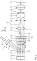
- Fig. 1 schematically shows a microlithography projection exposure system 1, which is designed as a wafer scanner and is used in the production of semiconductor assembly parts and other finely structured components.
- the projection exposure system 1 works to achieve resolutions to fractions of micrometres with light, in particular from the deep ultraviolet range (DUV or VUV).
- DUV deep ultraviolet range
- a Cartesian xyz coordinate system is reproduced in the drawing.
- the x-direction runs upwardly in Fig. 1 .
- the y-direction runs perpendicular to the plane of the drawing in Fig. 1 and out of it.
- the z-direction runs to the right in Fig. 1 .
- a scanning direction of the projection exposure system 1 runs in the y-direction, in other words perpendicular to the plane of the drawing in Fig. 1 .
- the plurality of optical components of the projection exposure system 1 is arranged in a row along an optical axis 2 running in the z-direction. It is obvious that convolutions of the optical axis 2 other than shown in Fig. 1 are possible, in particular in order to make the projection exposure system 1 compact.
- An illumination system designated as a whole by 5 of the projection exposure system 1 is used for the defined illumination of an object or illumination field 3 in an object or reticle plane 4, in which a structure to be transferred in the form of a reticle, not shown in more detail, is arranged.
- the illumination system 5 comprises a primary light source 6 and an illumination optical system 7 with the optical components for guiding illumination or imaging light 8 to the object field 3.
- the primary light source 6 is an ArF laser with a working wavelength of 193 nm, the illumination light beam of which is oriented coaxially with respect to the optical axis 2.
- Other UV light sources for example an F 2 excimer laser with a 157 nm working wavelength, a KrF excimer laser with a 248 nm working wavelength and primary light sources with larger or smaller working wavelengths are also possible.
- the beam widening optical system 9 may contain elements which reduce undesired effects of the coherence of the illumination light 8.
- the illumination light 8 substantially parallelised by the beam widening optical system 7 then impinges on a micro mirror array (Multi Mirror Array, MMA) 10 to produce an illumination light angle distribution.
- the micro mirror array 10 has a large number of rectangular individual mirrors 11 arranged in an xy-raster. Each of the individual mirrors 11 is connected to an associated tilting actuator 12.
- Each of the tilting actuators 12 is connected by a control line 13 to a controller 14 to activate the actuators 12.
- the actuators 12 can be actuated independently of one another by the controller 14.
- Each of the actuators 12 can adjust a predetermined x-tilting angle (tilting in the xz-plane) and, independently thereof, a y-tilting angle (tilting in the yz-plane) of the individual mirror 11, so that an angle of reflection AS x of an illumination light part bundle 15 reflected by the associated individual mirror 11 can be predetermined in the xz-plane and, accordingly, an angle of reflection AS y , not shown in the drawing, can be predetermined in the yz-plane.
- the angle distribution produced by the MMA 10 of angles of reflection AS of the illumination light part bundles 15 is transformed when passing through a Fourier lens arrangement or a capacitor 16, which is positioned at the spacing of its focal length from the MMA 10, into a two-dimensional, location-dependent illumination light intensity thus distribution perpendicular to the optical axis 2.
- the intensity distribution thus produced is therefore present in a first illumination plane 17 of the illumination system 5.
- the MMA 10 is thus a light distribution device to produce a two-dimensional illumination light intensity distribution.
- a first raster arrangement 18 of a raster module 19 Arranged in the region of the first illumination plane 17 is a first raster arrangement 18 of a raster module 19, which is also called a honeycomb capacitor. Angles of incidence ER x in the xz-plane (cf Fig. 1 ) and ER y in the yz-plane (not shown in the drawing) of the illumination light 8 on the raster module 19 are correlated to the angles of reflection AS x (cf Fig. 1 ), AS y (not shown in the drawing) of the illumination light part bundles 15 from the MMA 10 and/or the location, from which the respective illumination light part bundle 15 is emitted from the MMA 10, in other words the respective individual mirror 11. This correlation is predetermined by the Fourier lens arrangement 16.
- the impingement locations of the illumination light part bundles 15 on the first raster arrangement 18 are directly correlated to the angles of reflection AS x , AS y of the illumination light part bundles 15 from the MMA 10, as on the raster arrangement 18, the angles of reflection are AS x and AS y , as the Fourier lens arrangement 16 approximately leads to a conversion of angles into location coordinates.
- the angles of incidence ER x , ER y of the illumination light part bundles 15 on the raster module 19 are directly correlated with the positions of the illumination light part bundles 15 on the MMA 10, in other words with the individual mirror 11, from which the respective illumination light part bundle 15 is emitted, as both the use of a Fourier lens arrangement 16 and the use of a capacitor 16 leads to a conversion of location coordinates into angles.
- the raster module 19 is used to produce a spatially distributed arrangement of secondary light sources, in other words of images of the primary light source 6 and therefore to the production of a defined illumination angle distribution of the illumination light leaving the raster module 19.
- a second raster arrangement 21 is arranged in a further illumination plane 20.
- the illumination plane 17 is in or close to a front focal plane of individual elements of the second raster arrangement 21.
- the two raster arrangements 18, 21 are a honeycomb capacitor of the illumination optical system 7.
- the further illumination plane 20 is a pupil plane of the illumination system 5 or is adjacent to a pupil plane of the illumination system 5.
- the raster module 19 is therefore also designated the field-defining element (FDE).
- the emergent angles AR x in the xz-plane (cf. Fig. 1 ) and AR y in the yz-plane (not shown in the drawing), at which the illumination light part bundles 15 leave the second raster arrangement 21, are precisely allocated to a location region in the object field 3, on which the respective illumination light part bundle 15 impinges on the object field 3.
- a further capacitor 22 Arranged downstream of the raster module 19 is a further capacitor 22, which is also called a field lens. Together with the second raster arrangement 21, the capacitor 22 images the first illumination plane 17 in a field intermediate plane 23 of the illumination system 5.
- a reticle marking system (REMA) 24 which is used as an adjustable shading mask to produce a sharp edge of the illumination light intensity distribution, may be arranged in the field intermediate plane 23.
- a following lens system 25 images the field intermediate plane 23 on the reticle, in other words, the lithography master, which is located in the reticle plane 4.
- the reticle plane 4 is imaged on a wafer or image plane 27 on the wafer, not shown in Fig. 1 , which is intermittently or continuously displaced in the scanning direction (y).
- the first raster arrangement 18 has individual first raster elements 28, which are arranged column-wise and line-wise in the xy-plane.
- the first raster elements 28 have a rectangular aperture with an x/y aspect ratio of, for example, 1/1.
- the meridional section according to Fig. 1 runs along a raster column.
- the first raster elements 28 are configured as microlenses, for example with a positive refractive power.
- the first raster elements 28 are arranged directly adjacent to one another in a raster corresponding to their rectangular shape, in other words, substantially filling the area.
- the first raster elements 28 are also called field honeycombs.
- the raster construction and the function of the raster module 19 basically correspond to that which is described in WO2007/093433 A1 .
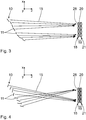
- Fig. 2 illustrates a course of two illumination light part bundles 15 1 and 15 2 from the MMA 10 to the second raster arrangement 21 of the raster module 19.
- a central angle of reflection, angle of incidence or emergent angle of the respective illumination light part bundle 15 is always shown.
- Angles of reflection AS x of two illumination light part bundles 15 from the MMA 10, an angle of incidence ER x of one of the two illumination light part bundles 15 on the second raster arrangement 21 (the corresponding central angle of incidence of the other illumination light part bundle is zero) and emergent angles AR x of the illumination light part bundles 15 from the raster module 19 are shown by way of example in Fig. 2 .
- No refractive effect of the Fourier lens arrangement 16 is shown in a simplified manner in Fig. 2 .
- a refractive effect of this type is present, such that an angle of reflection AS x of the illumination light part bundles 15 from the MMA 10 does not coincide with the respective angle of incidence ER x of the illumination light part bundles 15 on the first raster arrangement 18.
- a correlation of the angle of reflection AS x of the respective illumination light part bundle 15 from the MMA 10 and of the location, from which the respective illumination light part bundle 15 is emitted from the MMA 10 to the angle of incidence ER x of the same illumination light part bundle 15 on the first raster arrangement 18 is provided.
- the illumination light part bundle 15 1 shown at the top in Fig. 2 is guided from the individual mirror 11 1 of the MMA 10 shown right at the top in Fig. 2 at an angle of reflection AS x1 via the Fourier lens arrangement or the capacitor 16 to the first raster element 28, shown as second from the top, of the first raster arrangement 18 of the raster module 19.
- the illumination light part bundle 15 1 impinges at an angle of incidence on the first raster arrangement 18, which is only the same as the angle of reflection AS x1 in the view of Fig. 2 disregarding the refractive effect of the Fourier lens arrangement 16.
- the illumination light part bundle 15 1 After passing through this first raster arrangement 28, the illumination light part bundle 15 1 impinges on a first location region 29 of a second raster element 30 of the second raster arrangement 21.
- This first location region 29 corresponds to the diameter of the illumination light part bundle 15 1 impinging on the second raster element 30 and predetermines a first impingement location for illumination light on the second raster element 30.
- the second raster elements 30 of the second raster arrangement 21, in each case allocated to the channels, are arranged in the light path behind the first raster elements 28 of the first raster arrangement 18.
- the second raster elements 30 are also configured as microlenses with, in particular, a positive refractive power.
- the second raster elements 30 are also called pupil honeycombs, which are arranged in the second illumination plane 20, in other words in a pupil plane of the illumination optical system 7.
- the second illumination plane 20 is conjugated to a pupil plane 31 of the projection lens system 26.
- the images of the first raster elements 28 are thus superimposed in the field intermediate plane 23.
- Fig. 1 shows the raster elements 28, 30 schematically as plano-convex lenses.
- the raster elements 28, 30 are also schematically shown as biconvex lenses.
- the second illumination light part bundle 15 2 shown in Fig. 2 is guided from the individual mirror 11 2 of the MMA 10, shown as the second from the bottom, to the same first raster element 28 as the first illumination light part bundle 15 1 shown in Fig. 2 .
- An angle of reflection AS x2 of the illumination light part bundle 15 2 from the individual mirror 11 2 has the opposite sign to the angle of reflection AS x1 of the illumination light part bundle 15 1 in the view according to Fig. 2 disregarding the refractive effect of the Fourier lens arrangement 16.
- the angle of reflection AS x2 of the illumination light part bundle 15 2 from the individual mirror 11 2 may be approximately identical to the angle of reflection AS x1 of the illumination light part bundle 15 1 if these impinge upon the same raster element 28 of the first raster arrangement 18. Because of the fact that the illumination light part bundles 15 1 , 15 2 are emitted from different locations from the MMA 10, in other words from different individual mirrors 11, and therefore impinge at different locations on the Fourier lens arrangement 16, a difference is then nevertheless produced between the two angles of incidence of the illumination light part bundles 15 1 , 15 2 on the first raster arrangement 18. This situation, in which the same angles of incidence of various illumination light part bundles 15 1 , 15 2 are transferred to the Fourier lens arrangement 16 at different emergent angles, is not shown in Fig. 2 , as already mentioned.
- the second illumination light part bundle 15 2 After passing through the first raster element 28, the second illumination light part bundle 15 2 impinges on a second location region 29' of the same second raster element 30 as the first illumination light part bundle 15 1 .
- the second location region 29' specifies an impingement location of the second illumination light part bundle 15 2 on this second raster element 30.
- the two location regions 29 and 29', in which the two illumination light part bundles 15 1 , 15 2 impinge on the second raster element 30, are spatially separated from one another in the embodiment shown.
- Alternative embodiments are possible, in which the location regions 29 and 29', in which the two illumination light part bundles 15 1 , 15 2 impinge on the second raster element 30, partially overlap one another.
- Fig. 2 illustrates two alternatively possible effects of the second raster arrangement 21 and the second raster element 30: in a first bundle guidance shown by a continuous line in Fig. 2 , the same emergent angles AR x1 , AR x2 results for the two illumination light part bundles 15 1 , 15 2 being emitted from the second raster element 30.
- the emergent angle AR x is independent of the impingement location 29 or 29' of the respective illumination light part bundle on the second raster element 30.
- an alternative optical effect shown by dash-dot lines in Fig.
- the emergent angle AR x2 for the illumination light part bundle 15 2 is smaller than the emergent angle AR x1 for the illumination light part bundle 15 1 .
- the angle of reflection AR x thus depends on the impingement location 29 on the second raster element 30.
- the emergent angle AR x can also depend on an angle of incidence ER x of the respective illumination light part bundle 15 on the second raster element 30 of the second raster arrangement 21. This angle of incidence ER x is shown by way of example in Fig. 2 for the illumination light part bundle 11 2 .
- a corresponding dependency is present between the angle of incidence ER x of the respective illumination light part bundle 15 on the first raster element 28 of the first raster arrangement 18 and the emergent angle AR x .
- the second raster elements 30 are often configured in such a way that the emergent angle AR x depends on a combination of the angle of incidence ER x and the impingement location 29 on the second raster element 30.
- the impingement location or location region 29 (or 29', cf Fig. 2 ) will also be called AO below.
- the surface design of an entry face 33 and/or an exit face 34 of the second raster elements 30 of the second raster arrangement 21 of the raster module 19 can be designed in such a way that for specific emergent angles AR x , this emergent angle is identical for specific combinations of the impingement location of the illumination light part bundle 15 on the second raster element 30 and the angle of incidence ER x of the illumination light part bundle 15 on this second raster element 30, while for other exit angles, AR x is in turn dependent on the impingement location and/or on the angle of incidence ER x .
- This can be used, on the one hand, to sharply define the field edges of the object field 3 and, on the other hand, to predetermine an intensity distribution of specific illumination directions on the object field 3, as will be described below.
- the entry faces 33 and/or the exit faces 34 of the raster elements 30 may be spherical, aspherical and, in particular conical in design.
- the controller 14 is configured in such a way that a predetermined distribution of actual tilting angles of the individual mirrors 11 of the MMA 10 and, as a result, a predetermined distribution of actual angles of incidence ER x , ER y of the illumination light part bundles 15 on the first raster elements 28 is allocated to a predetermined desired course of illumination angle intensity distributions, with which object field points over the object field 3 are impinged upon.
- the MMA 10 is shown there with individual mirrors 11, which are arranged next to one another at an angle, which differs from the zero, with respect to the x-axis. Otherwise, the MMA 10 according to Figs. 3 and 4 corresponds to the MMA 10 according to Fig. 1 .
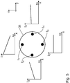
- four pupil or intensity spots I 1 to I 4 are thus illuminated in the pupil plane 31 and are shown in Fig. 5 , and are numbered consecutively beginning with the intensity spot I 1 shown uppermost in the anti-clockwise direction.
- Fig. 3 shows a first distribution of actual tilting angles of the individual mirrors, which leads to a corresponding distribution of actual angles of incidence ER x of the illumination light part bundles 15 on the first raster elements 28 of the first raster arrangement 18 of the raster module 19.
- the actual tilting angle distribution according to Fig. 3 leads to minimal angles of incidence ER x , ER y of the illumination light part bundles 15 on the first raster elements 28 of the raster module 19 and as a result leads to the fact that everywhere in the object field 3, in other words independently of the field, the four illumination directions, which correspond to the intensity spots I 1 to I 4 , are represented with the same intensity of the illumination light.
- Fig. 4 shows a variant of a distribution of actual tilting angles of the individual mirrors 11 of the MMA 10, which also leads to the quadrupole illumination setting with the four intensity spots (poles) I 1 to I 4 according to Fig. 5 , but with a different distribution of actual angles of incidence ER x , ER y of the illumination light part bundles 15 on the first raster elements 28 of the raster module 19.
- the actual tilting angle distribution according to Fig. 4 is such that, in comparison to Fig. 3 , substantially greater angles of incidence ER x , ER y result.
- the raster elements 28, 30 impinged upon by the illumination light part bundle 15 in the illumination according to Figs.
- FIG. 3 and 4 are configured such that the increase in the angle of incidence in the actual angle of incidence distribution according to Fig. 4 can lead to a tilting of the illumination angle intensities I(x) from the direction of the four intensity spots I 1 to I 4 over the object field 3.
- the effect on which this tilting is based is described in WO 2007/093433 A1 , where this tilting was produced by means of an additional illumination angle variation device of the raster module, in other words not by means of an MMA.
- An actual course of illumination angle intensity distributions resulting on the basis of the actual angle of incidence distribution according to Fig. 4 , with which object field points are impinged upon over the object field, is shown in Fig. 5 for the four illumination directions I 1 to I 4 of the quadrupole illumination setting there.
- FIG. 4 Only a part of the illumination light part bundles 15 is drawn in Fig. 4 , which lead to the field dependency according to Fig. 5 .
- the corresponding field dependency of the illumination intensity from the direction of the pole I 2 is shown on the left in Fig. 5 .
- the I 2 -intensity increases linearly, proceeding from the left field edge to the right field edge.
- the I(x)-dependency for the I 3 -pole is shown at the bottom in Fig. 5 .
- the intensity I 3 (x) from the direction of the I 3 -pole is independent in relation to the field coordinates (x).
- the I x -dependency for the illumination intensity from the direction of the I 4 -pole is shown on the right in Fig. 5 .
- the illumination intensity I 4 (x) from the direction of the I 4 -pole rises proceeding from the left field edge to the right field edge with a slope which is smaller in comparison to the slope of the dependency I 2 (x).
- a large bandwidth of other desired courses of illumination angle intensity distributions, with which object field points are impinged upon over the object field, can be predetermined.
- a desired distribution of angles of incidence ER x , ER y of the illumination light part bundles 15 on the raster elements 28 of the raster module 19 is then firstly determined for the predetermined desired course, during the adjustment of the illumination optical system 7 to prepare the operation of the projection exposure system 1.
- a distribution of desired tilting angles of the individual mirrors 11 is then allocated to this determined desired angle of incidence distribution.
- a desired tilting angle is therefore predetermined for each individual mirror 11.
- the tilting actuators 12 of the individual mirrors 11 are activated in such a way that the actual tilting angles of the individual mirrors 11 coincide with the associated desired tilting angles.
- a degree of dependency of the desired course I(x) of the illumination angle intensity distributions, with which the object field points are impinged upon over the object field 3, on the distribution of actual angles of incidence ER x , ER y of the illumination light part bundles 15 on the first raster elements 28 or ER x , ER y on the second raster elements 30 can be influenced by the positional relationship of the two raster arrangements 18, 21 of the raster module 19 with respect to the at least one pupil plane of the illumination optical system 7.
- the second illumination plane 20 coincides with a pupil plane of the illumination optical system 7 or whether a defined spacing is present between the second illumination plane 20 and the pupil plane of the illumination optical system 7, a weaker or stronger dependency of the desired course of illumination angle intensity distributions on the actual angle of incidence ER x may result.
- predetermined intensity distributions of the illumination light part bundles 15 on the raster module 19 and correspondingly predetermined intensity distributions in the pupil plane 31 may result.
- a further example to supplement the quadrupole intensity distribution described above in conjunction with Fig. 3 to 5 is a dipole intensity distribution, in which two pupil or intensity spots are illuminated in the pupil plane 31, the position of which may correspond to that of the intensity spots I 1 and I 3 in the view according to Fig. 5 .
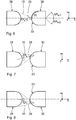
- the ratios in the guidance of an illumination light part bundle 15 with the two raster elements 28, 30, allocated to a light channel, of the raster arrangements 18, 21 of the raster module 19 will be described in detail below with the aid of Figs. 6 to 8 .
- the raster elements 28, 30 are in turn shown as plano-convex lenses in Figs. 6 to 8 . These may just as well be biconvex lenses.
- the course of the illumination light part bundle 15 focused between the raster elements 28 and 30 is symmetrical to the z-axis.
- the location region 29, in other words the diameter of the illumination light part bundle 15, is smaller than one half 35 of the total entry face 33 of the second raster element 30. Another area-size ratio between the location region 29 and the total entry face 33 is also possible.
- Fig. 7 shows a variant of a guidance of the illumination light part bundle 15 at an angle of incidence ER x on the second raster element 30 in the order of magnitude of 15°.
- the impingement location 29 of the illumination light part bundle 15, in the bundle guidance according to Fig. 7 lies completely in a half-plane located above the z-axis, in other words an axis of symmetry of the raster elements 28, 30.
- Fig. 8 shows a further variant of a bundle guidance of the illumination light part bundle 15 at an angle of incidence ER x on the second raster element 30 with an opposite sign in comparison to the situation according to Fig. 7 , but the same absolute size.
- the impingement location 29 of the illumination light part bundle 15 on the entry face 33 of the second raster element 30, in the bundle guidance according to Fig. 8 lies completely in the half-plane located below the z-axis.
- the impingement locations 29 there in other words the diameters of the illumination part bundle 15, which impinges on the second raster element 30, are completely separate from one another.
- a characteristic of a dependency of the emergent angle AR x of the illumination light part bundle 15 from the second raster element 30 on the angle of incidence ER x which is shown in Figs. 6 to 8 , can therefore be influenced by a suitable design of the entry face 33 of the second raster element 30.
- Fig. 9 schematically shows a dependency of emergent angles AR x , proceeding from the raster module 19, on the one hand on the angle of incidence ER x on the respective second raster element 30 and, on the other hand, on the impingement location AO of the respective illumination light part bundle 15 on the second raster element 30.
- the edges of the first raster element 28 are imaged on the field edges of the object field 3. Isolines of two emergent angles AR xr1 and AR xr2 , which define the two opposing x-field edges of the object field 3, are therefore produced in Fig. 9 .
- One field edge emergent angle AR xr1 is produced in each case for a given parameter pair (ER x ; AO) and the other field edge emergent angle AR xr2 is produced for another linear course of parameter pairs (ER x ; AO).
- This course of the parameter pairs is also called isolines 36, 37 for the field edge emergent angles AR xr1 , AR xr2 .
- the same emergent angle AR xr1 ⁇ 2 always results, so the field edges of the object field 3 in the x-direction, in other words the left field edge in the x-direction and the right field edge in the x-direction of the object field 3, remain sharply defined.
- the parameter pair dependencies do not have to run linearly, as shown in Fig. 9 , but may also have a different course. The linear course shown in Fig. 9 may lead to a homogenous illumination of the object field at the field edges.
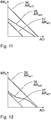
- Fig. 10 shows a view corresponding to Fig. 9 , a third isoline 38 for a third emergent angle AR xm defining an object field centre in the x-direction also being shown in addition to the isolines 36, 37 for the two field edge emergent angles.
- the isoline 38 extends equidistantly between the two isolines 36 and 37, which leads to a homogenous illumination of the object field 3 with the illumination light 8.
- Fig. 11 shows a variant of the course of the isoline 38 for the emergent angle AR xm defining the object field centre in the x-direction.
- the angles of incidence ER x for the isolines 37 and 38 are located close together. This means that, the angle of incidence ER xm , which leads to the emergent angle AR xm for the object field centre is already located, with regard to the impingement location on the respective second raster element 30 close to the angle of incidence ER x , which leads to the emergent angle AR xr2 for, for example, the left edge of the object field 3 in the x-direction.
- Fig. 12 shows by way of example a further course possibility of the isoline 38 for the emergent angle AR xm defining the object field centre.
- the isoline 38 changes from a course adjacent to the isoline 37 to a course adjacent to the isoline 36.
- the transition between stronger illumination of the left object field half to a stronger illumination of the right object field half is accordingly more abrupt depending on the respectively used region of the impingement locations.
- the situation according to Fig. 12 is approximately a limit case, in other words an arrangement, in which the face region 29 on one half of the entry face 33 of the raster element 30 illuminates one half of the object or illumination field 3 and the face region 29 opposing this (cf. Figs. 6 and 7 ) on the other half of the entry face 33 of the raster element 30 illuminates the other half of the object or illumination field 3.
- Fig. 13 shows an example of the structuring of the entry face 33 of one of the second raster elements 30 in order to achieve the limit case mentioned above.
- a conical contribution 40 is superposed on a spherical basic course 39 of the entry face 33, or an aspherical one with regard to the dependency on the spacing from the optical axis, said basic course being shown by dashed lines in Fig. 13 , so the entry face 33 is elevated centrally in the manner of a roof edge. The location of this elevation is illustrated in Fig. 13 by K.
- the elevation K may be absolutely selected such that owing to the raster element 30 having the elevation K, the incident illumination light part bundle 15 is deflected in the x-direction by half a width of the object field 3, as will be described below with the aid of Fig. 14 to 16 .
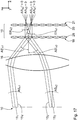
- a raster module 19 with a second raster arrangement 21 with second raster elements 30, the entry faces 33 of which are formed according to the design according to Fig. 13 is illustrated with the aid of Figs. 14 to 16.
- Figs. 14 to 16 in turn show the raster elements 28, 30 as biconvex lenses.
- the MMA 10 is shown divided into two parts, which are separated from one another. Each of these parts may have a plurality of individual mirrors 11 which can be individually tilted with respect to one another. A subdivision of the MMA 10 into a larger number of parts each with a plurality of individual mirrors 11 is also possible.
- Fig. 14 shows an illumination of the raster module 19 in the xz-plane from incidence directions with first angles of incidence ER xI .
- this illumination takes place obliquely from the top left.
- a displacement is produced of the illumination light part bundle 15 guided by the raster module 19 in the object field 3 to positive x-values, which is shown in the I(x)-graph of Fig. 14 at the bottom.
- the illumination according to Fig. 14 only the right object field half thus sees light from the direction of the pupil spot, which corresponds to the illuminated raster elements 28, 30.
- Fig. 15 shows the illumination of the same second raster element 30, but now with an angle of incidence ER xII with an opposite sign, in other words obliquely from the top right in the arrangement according to Fig. 15 .
- a displacement results of the illumination light part bundle 15 thus guided in the object field 3 in the negative x-direction, as shown in the I(x)-graph of Fig. 15 at the bottom.
- only the left object field half thus sees light from the direction of the pupil spot, which corresponds to the illuminated raster elements 28, 30.
- Fig. 16 shows the combination of the illuminations according to Figs. 14 and 15 .
- the entire object field is now illuminated from the direction of the illuminated raster elements 28, 30, in other words from the direction of the associated pupil spot.
- No additional I(x)-graph is shown in Fig. 16 .
- This I(x)-graph is produced form a superposition of the two I(x)-graphs of Fig. 14 and 15 .
- a desired dependency AR(ER, AO) of a course of resulting constant emergent angles AR x of the illumination light part bundles 15 from the second raster elements 30 depending on the impingement location AO of the illumination light part bundles 15 on these raster elements 30 and depending on the angles of incidence ER x of the illumination light part bundles 15 on these raster elements 30 can be predetermined.
- the entry faces 33 and optionally also the exit faces 34 of the second raster elements 30 are then structured in such a way that at a predetermined illumination of the raster module 19, an actual dependency of the emergent angle course is produced, which corresponds to the predetermined desired dependency.
- classes of desired dependencies AR(ER, AO) of a course of resulting constant emergent angles AR x of the illumination light part bundles 15 from the second raster elements 30 are determined depending on the impingement location AO of the illumination light part bundles 15 on these raster elements 30 of the second raster arrangement 21 and depending on the angle of incidence ER x of the illumination light part bundles 15 on these raster elements 30, which can be achieved with typical face designs of the entry faces 33 and/or the exit faces 34 of the second raster elements 30.
- These classes of desired dependencies AR(ER, AO) may have isoline courses of parameter pairs of angles of incidence ER x and of impingement locations AO, which lead to the same emergent angles AR x , as described above in conjunction with Figs. 9 to 12 .
- a desired dependency AR(ER, AO) obtained in one of the classes determined is then predetermined and the entry faces 33 and/or the exit faces 34 of the raster elements 30 of the second raster arrangement 21 are structured in such a way that with a predetermined illumination of the raster module 19, an actual dependency of the course is produced, which corresponds to the predetermined desired dependency within predetermined tolerance limits.
- the effect of the raster module 19 on the illumination light part bundles 15 was described above primarily in the xz-plane. Corresponding effects and dependencies are also produced in the yz-plane.
- This can be used in order to define the y-field edges of the object field 3 and to also predetermine an intensity distribution from the illumination angles predetermined by an illumination setting over the object field 3 in the y-direction. This may, in particular, be used in the case of the configuration of the projection exposure system 1 as a stepper, in which the entire object field 3 is simultaneously, in other words, not by a scanning method, illuminated and imaged.
- the raster elements 28, 30 are dioptric, in other words refractive raster elements.
- the raster elements 28, 30 may also be designed as catoptric, in other words reflective raster elements.
- Fig. 17 shows an arrangement corresponding to Fig. 2 , the refractive effect of the Fourier lens arrangement 16 being shown.
- Components which correspond to those which have already been discussed above with reference to the figures already described and, in particular, with reference to Fig. 2 have the same reference numerals and will not be described again in detail.
- the course of two illumination light part bundles 15 1 and 15 2 from the respective individual mirrors 11 1 and 11 2 of the micro mirror array 10 is in turn shown.
- the two part bundles 15 1 , 15 2 have angles of reflection AS x1 and AS x2 from the individual mirrors 11 1 and 11 2 .
- the refractive effect of the Fourier lens arrangement 16 leads to the conversion of these angles of reflection AS x1 and AS x2 to angles of reflection AS' x1 and AS' x2 after the Fourier lens arrangement 16.
- the angles of incidence ER x1 and ER x2 of the two illumination light part bundles 15 1 , 15 2 on the entry face 33 of the same raster element 30 of the second raster arrangement 21 are also shown. In the view according to Fig.
- Fig. 17 this is the third raster element 30 from the top.
- Fig. 17 now shows the situation in which the same angles of incidence on the Fourier lens arrangement 16, in other words the angles AS x1 and AS x2 are transferred into different angles of reflection AS' x1 and AS' x2
- Fig. 17 in turn shows two alternatively possible effects of the second raster arrangement 21 and the raster element 30 acted upon by the two part bundles 15 1 , 15 2 .
- a first bundle guidance shown by a continuous line in Fig. 17 the same emergent angle AR x1 , AR x2 results for the two illumination light part bundles of 15 1 , 15 2 leaving the raster element 30 of the second raster arrangement 21.
- these emergent angles AR x1 and AR x2 are in each case zero.
- an alternative optical effect of the second raster arrangement 21 shown by a dot-dash line in Fig.
- an emergent angle AR x1' less than zero results for the illumination light part bundle 15 1 , in other words with a course component in the negative x-direction, and an emergent angle AR x2' greater than zero, in other words with a course component in the positive x-direction results for the part bundle 15 2 .
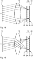
- Fig. 18 to 20 show alternative illuminations for the raster module 19, which, in the second illumination plane 20, in each case lead to the impingement of the same raster elements 30, but with different distributions of angles of incidence ER x .
- the refractive effect of the Fourier lens arrangement is taken into account in Fig. 18 to 20 . Because of the different angles of incidence of the part bundles 15 on the raster elements 28 and 30 of the two raster arrangements 18 and 21, different field-dependent effects of the illumination of the object field 3 can be produced, as already described above.
- a substrate or a wafer in the wafer plane 27 is firstly provided for the microlithographic production of microstructured or nanostructured components with the projection exposure system 1. At least one layer of a light-sensitive material is applied to the wafer. A reticle having structures to be imaged is furthermore provided in the reticle plane 4. The part of the reticle arranged in the object field 3 is then projected, using the projection exposure system 1, onto a region of the layer arranged in the image field.
Claims (10)
- Optisches Beleuchtungssystem (7) für Mikrolithographie zum Führen von Beleuchtungslicht (8) von einer Primärlichtquelle (6) zu einem Objektfeld (3),- mit einem Spiegelarray (10) mit einer Vielzahl von Einzelspiegeln (11), die unabhängig voneinander durch Aktuatoren kippbar sind und mit zugehörigen Kippaktuatoren (12) verbunden sind,- mit einer Steuerung (14) zum Aktivieren der Aktuatoren (12),- mit einem Rastermodul (19) mit einer Vielzahl von Rasterelementen (28, 30) zum Erzeugen einer räumlich verteilten Anordnung von Sekundärlichtquellen,- wobei das Rastermodul (19) im Bereich einer Ebene (20) des optischen Beleuchtungssystems (7) angeordnet ist, in der ein Austrittswinkel (ARx, ARy), unter dem ein Beleuchtungslichtteilbündel (15) eines der Rasterelemente (28, 30) verlässt, genau einem Positionsbereich im Objektfeld (3) zugeordnet ist, auf den das Beleuchtungslichtteilbündel (15) auf das Objektfeld (3) auftrifft,- wobei die Steuerung (14) derart ausgelegt ist, dass eine Spezifikation eines Kippwinkels für jeden Einzelspiegel (11) einem vorbestimmten feldabhängigen Sollverlauf von Beleuchtungswinkel-Intensitätsverteilungen (I1(x), I2(x), I3(x), I4(x)) zugeordnet ist, mit denen über das Objektfeld (3) verteilte Objektfeldpunkte bestrahlt werden,- wobei das Rastermodul (19) zwei im Strahlengang des Beleuchtungslichts (8) hintereinander angeordnete Rasteranordnungen (18, 21) mit jeweils einer Vielzahl von Rasterelementen (28, 30) aufweist,- dadurch gekennzeichnet, dass die Anordnung und Auslegung der zwei Rasteranordnungen (18, 21) derart ist, dass ein Durchmesser (29) des Beleuchtungslichtteilbündels (15), das auf eines der Rasterelemente (30) der zweiten Rasteranordnung (21) auftrifft, kleiner ist als die Hälfte (35) einer gesamten Eintritts- oder Auftrefffläche (33) des Rasterelements (30) der zweiten Rasteranordnung (21).
- Optisches Beleuchtungssystem nach Anspruch 1, dadurch gekennzeichnet, dass das Rastermodul (19) in einer Ebene (20) des optischen Beleuchtungssystems (7) angeordnet ist, die an eine Pupillenebene (31) oder eine dazu konjugierte Ebene angrenzt und von dieser beabstandet ist.
- Optisches Beleuchtungssystem nach Anspruch 1 oder 2, dadurch gekennzeichnet, dass die zwei Rasteranordnungen (18, 21) zumindest für spezifische Austrittswinkel (ARxr1, ARxr2) der Beleuchtungslichtteilbündel (15) derart ausgelegt sind, dass sich in Abhängigkeit vom Auftreffort (AO) auf die Rasterelemente (30) der zweiten Rasteranordnung (21) zumindest für Einfallswinkel (ERx) , die in jedem Fall dem jeweiligen Auftreffort (AO) zugeordnet sind, des Beleuchtungslichtteilbündels (15) auf die Rasterelemente (30) der zweiten Rasteranordnung (21) der gleiche Austrittswinkel (ARxr1, ARxr2) der Beleuchtungslichtteilbündel (15) aus dem Rasterelement (30) ergibt.
- Optisches Beleuchtungssystem nach einem der Ansprüche 1 bis 3, dadurch gekennzeichnet, dass die zwei Rasteranordnungen (18, 21) zumindest für spezifische Austrittswinkel (ARxm) der Beleuchtungslichtteilbündel (15) derart ausgelegt sind, dass kleine Änderungen des Einfallswinkels (ERx) der Beleuchtungslichtteilbündel (15) auf die Rasterelemente (30) der zweiten Rasteranordnung (21) zu großen Änderungen des Austrittswinkels (ARx) der Beleuchtungslichtteilbündel (15) aus den Rasterelementen (30) führen.
- Optisches Beleuchtungssystem nach Anspruch 3 oder 4, dadurch gekennzeichnet, dass die Abhängigkeit der Änderungen des Einfallswinkels (ERx) der Beleuchtungslichtteilbündel (15) auf die Rasterelemente (30) auf die Änderungen des Austrittswinkels (ARx) der Beleuchtungslichtteilbündel (15) aus den Rasterelementen (30) über den Auftreffort (AO) variiert.
- Optisches Beleuchtungssystem nach einem der Ansprüche 1 bis 5, dadurch gekennzeichnet, dass das Rastermodul (19) und die Steuerung (40) derart ausgelegt sind, dass eine vorbestimmte Verteilung tatsächlicher Kippwinkel der Einzelspiegel (11) und in der Folge eine vorbestimmte Verteilung tatsächlicher Einfallswinkel (ERx, ERy) der Beleuchtungslichtteilbündel (15) auf die Rasterelemente (28, 30) einem vorbestimmten Sollverlauf von Beleuchtungslicht-Winkelintensitätsverteilungen I1(x, y), I2(x, y) , I3(x, y) , I4(x, y) zugeordnet ist, mit denen über das Objektfeld (3) verteilte Objektfeldpunkte bestrahlt werden, und diese Zuordnung entlang zweier zueinander senkrechter Dimensionen (x, y) des Objektfeldes (3) vorliegt.
- Verfahren zum Justieren eines optischen Beleuchtungssystems (7) nach einem der Ansprüche 1 bis 6, umfassend die folgenden Schritte:- Vorbestimmen eines feldabhängigen Sollverlaufs von Beleuchtungswinkel-Intensitätsverteilungen (I1(x), I2(x), I3(x), I4(x), mit denen über das Objektfeld (3) verteilte Objektfeldpunkte bestrahlt werden sollen,- Bestimmen einer dem vorbestimmten feldabhängigen Sollverlauf der Beleuchtungswinkel-Intensitätsverteilungen zugeordneten Verteilung von Soll-Einfallswinkeln (ERx, ERy) der Beleuchtungslichtteilbündel (15) auf die Rasterelemente (28, 30),- Zuweisen einer Verteilung von Soll-Kippwinkeln an die Einzelspiegel (11) gemäß der bestimmten Verteilung des Soll-Einfallswinkels (ERx, ERy),- Aktivieren der Kippaktuatoren (12), so dass die tatsächlichen Kippwinkel der Einzelspiegel (11) mit den Soll-Kippwinkeln übereinstimmen,- wobei Gruppen von Einzelspiegeln (11) den gleichen Soll-Kippwinkel aufweisen.
- Optisches System mit einem optischen Beleuchtungssystem (7) nach einem der Ansprüche 1 bis 6 und mit einem optischen Projektionssystem (26) zum Abbilden des Objektfeldes (3) in einem Bildfeld in einer Bildebene (27).
- Mikrolithographie-Projektionsbelichtungssystem (1) mit einem optischen System nach Anspruch 8 und einer Primärlichtquelle (6).
- Verfahren zur mikrolithographischen Herstellung von mikrostrukturierten oder nanostrukturierten Komponenten, umfassend die folgenden Schritte:- Bereitstellen eines Substrats, auf das zumindest teilweise eine Schicht eines lichtempfindlichen Materials aufgebracht ist,- Bereitstellen eines Retikels, das abzubildende Strukturen aufweist,- Bereitstellen eines Projektionsbelichtungssystems (1) nach Anspruch 9,- Projizieren mindestens eines Teils des Retikels auf einen Bereich der Schicht mit Hilfe des Projektionsbelichtungssystems (1).
Applications Claiming Priority (3)
| Application Number | Priority Date | Filing Date | Title |
|---|---|---|---|
| US35477210P | 2010-06-15 | 2010-06-15 | |
| DE102010030089A DE102010030089A1 (de) | 2010-06-15 | 2010-06-15 | Beleuchtungsoptik für die Mikro-Lithografie sowie Projektionsbelichtungsanlage mit einer derartigen Beleuchtungsoptik |
| PCT/EP2011/059427 WO2011157601A2 (en) | 2010-06-15 | 2011-06-08 | Illumination optical system for microlithography and projection exposure system with an illumination optical system of this type |
Publications (2)
| Publication Number | Publication Date |
|---|---|
| EP2583141A2 EP2583141A2 (de) | 2013-04-24 |
| EP2583141B1 true EP2583141B1 (de) | 2021-04-14 |
Family
ID=45020111
Family Applications (1)
| Application Number | Title | Priority Date | Filing Date |
|---|---|---|---|
| EP11723967.3A Active EP2583141B1 (de) | 2010-06-15 | 2011-06-08 | Optisches beleuchtungssystem für mikrolithografie und projektionsbeleichtungssystem mit einem derartigen optischen beleuchtungssystem |
Country Status (6)
| Country | Link |
|---|---|
| US (1) | US9933704B2 (de) |
| EP (1) | EP2583141B1 (de) |
| JP (1) | JP5753260B2 (de) |
| DE (1) | DE102010030089A1 (de) |
| TW (1) | TWI539240B (de) |
| WO (1) | WO2011157601A2 (de) |
Families Citing this family (8)
| Publication number | Priority date | Publication date | Assignee | Title |
|---|---|---|---|---|
| WO2014010552A1 (ja) * | 2012-07-10 | 2014-01-16 | 株式会社ニコン | 照明光学系、露光装置、およびデバイス製造方法 |
| JP5864771B2 (ja) * | 2012-10-08 | 2016-02-17 | カール・ツァイス・エスエムティー・ゲーエムベーハー | マイクロリソグラフィ投影露光装置の照明系 |
| DE102013213545A1 (de) | 2013-07-10 | 2015-01-15 | Carl Zeiss Smt Gmbh | Beleuchtungsoptik für die Projektionslithografie |
| JP6488298B2 (ja) | 2013-08-09 | 2019-03-20 | ケーエルエー−テンカー コーポレイション | 改善した検出感度のマルチスポット照明 |
| DE102014203348A1 (de) | 2014-02-25 | 2015-08-27 | Carl Zeiss Smt Gmbh | Bündelverteilungsoptik, Beleuchtungsoptik mit einer derartigen Bündelverteilungsoptik, optisches System mit einer derartigen Beleuchtungsoptik sowie Projektionsbelichtungsanlage mit einem derartigen optischen System |
| DE102014203347B4 (de) | 2014-02-25 | 2017-09-14 | Carl Zeiss Smt Gmbh | Beleuchtungsoptik für die Mikro-Lithografie sowie Projektionsbelichtungsanlage mit einer derartigen Beleuchtungsoptik |
| US9575412B2 (en) * | 2014-03-31 | 2017-02-21 | Taiwan Semiconductor Manufacturing Company, Ltd. | Method and system for reducing pole imbalance by adjusting exposure intensity |
| DE102014219112A1 (de) | 2014-09-23 | 2016-03-24 | Carl Zeiss Smt Gmbh | Beleuchtungsoptik für die Projektionslithographie sowie Hohlwellenleiter-Komponente hierfür |
Family Cites Families (18)
| Publication number | Priority date | Publication date | Assignee | Title |
|---|---|---|---|---|
| US6259513B1 (en) | 1996-11-25 | 2001-07-10 | Svg Lithography Systems, Inc. | Illumination system with spatially controllable partial coherence |
| JP3005203B2 (ja) | 1997-03-24 | 2000-01-31 | キヤノン株式会社 | 照明装置、露光装置及びデバイス製造方法 |
| EP1262836B1 (de) | 2001-06-01 | 2018-09-12 | ASML Netherlands B.V. | Lithographischer Apparat und Verfahren zur Herstellung einer Vorrichtung |
| JP2004245912A (ja) * | 2003-02-12 | 2004-09-02 | Ushio Inc | 光照射装置 |
| DE102004063848A1 (de) * | 2004-02-26 | 2005-09-15 | Carl Zeiss Smt Ag | Beleuchtungssystem für eine Mikrolithographie-Projektionsbelichtungsanlage |
| JP2006253529A (ja) * | 2005-03-14 | 2006-09-21 | Nikon Corp | 照明光学装置、露光装置、および露光方法 |
| KR101314974B1 (ko) | 2006-02-17 | 2013-10-04 | 칼 짜이스 에스엠티 게엠베하 | 마이크로리소그래픽 조명 시스템 및 이를 구비한 투사 노출장치 |
| US8587764B2 (en) | 2007-03-13 | 2013-11-19 | Nikon Corporation | Optical integrator system, illumination optical apparatus, exposure apparatus, and device manufacturing method |
| US8937706B2 (en) | 2007-03-30 | 2015-01-20 | Asml Netherlands B.V. | Lithographic apparatus and method |
| US8379187B2 (en) | 2007-10-24 | 2013-02-19 | Nikon Corporation | Optical unit, illumination optical apparatus, exposure apparatus, and device manufacturing method |
| KR101644660B1 (ko) * | 2007-11-06 | 2016-08-01 | 가부시키가이샤 니콘 | 조명 광학 장치 및 노광 장치 |
| US9636187B2 (en) | 2007-11-21 | 2017-05-02 | Misonix Incorporated | Atomized-fluid shield for surgery and method of use |
| EP2238513B1 (de) * | 2007-12-21 | 2011-11-02 | Carl Zeiss SMT GmbH | Beleuchtungsmethode |
| DE102008009600A1 (de) * | 2008-02-15 | 2009-08-20 | Carl Zeiss Smt Ag | Facettenspiegel zum Einsatz in einer Projektionsbelichtungsanlage für die Mikro-Lithographie |
| DE102009017941A1 (de) * | 2008-06-19 | 2009-12-24 | Carl Zeiss Smt Ag | Beleuchtungssystem für die Mikro-Lithographie sowie Projektionsbelichtungsanlage mit einem derartigen Beleuchtungssystem |
| EP2146248B1 (de) * | 2008-07-16 | 2012-08-29 | Carl Zeiss SMT GmbH | Beleuchtungssystem eines mikrolithografischen Projektionsbelichtungsgerätes |
| DE102008042462B4 (de) | 2008-09-30 | 2010-11-04 | Carl Zeiss Smt Ag | Beleuchtungssystem für die EUV-Mikrolithographie |
| DE102009009568A1 (de) * | 2008-10-20 | 2010-04-29 | Carl Zeiss Smt Ag | Optische Baugruppe zur Führung eines EUV-Strahlungsbündels |
-
2010
- 2010-06-15 DE DE102010030089A patent/DE102010030089A1/de not_active Withdrawn
-
2011
- 2011-06-08 EP EP11723967.3A patent/EP2583141B1/de active Active
- 2011-06-08 JP JP2013514638A patent/JP5753260B2/ja active Active
- 2011-06-08 WO PCT/EP2011/059427 patent/WO2011157601A2/en active Application Filing
- 2011-06-15 TW TW100120852A patent/TWI539240B/zh active
-
2012
- 2012-11-20 US US13/681,938 patent/US9933704B2/en active Active
Non-Patent Citations (1)
| Title |
|---|
| None * |
Also Published As
| Publication number | Publication date |
|---|---|
| TWI539240B (zh) | 2016-06-21 |
| EP2583141A2 (de) | 2013-04-24 |
| JP2013530534A (ja) | 2013-07-25 |
| US9933704B2 (en) | 2018-04-03 |
| WO2011157601A2 (en) | 2011-12-22 |
| US20130077076A1 (en) | 2013-03-28 |
| DE102010030089A1 (de) | 2011-12-15 |
| WO2011157601A3 (en) | 2012-02-23 |
| JP5753260B2 (ja) | 2015-07-22 |
| TW201219987A (en) | 2012-05-16 |
Similar Documents
| Publication | Publication Date | Title |
|---|---|---|
| US9933704B2 (en) | Microlithography illumination optical system and microlithography projection exposure apparatus including same | |
| KR101470769B1 (ko) | 마이크로리소그래픽 투영 노광 장치의 조명 시스템 | |
| US9804499B2 (en) | Illumination system of a microlithographic projection exposure apparatus | |
| US10088754B2 (en) | Illumination system for microlithography | |
| KR20160088365A (ko) | 마이크로리소그래피 투영 노광 장치의 조명 시스템 | |
| TW201702756A (zh) | 微影投射設備的操作方法 | |
| JP5585761B2 (ja) | マイクロリソグラフィのための光学要素及び照明光学系 | |
| US8724080B2 (en) | Optical raster element, optical integrator and illumination system of a microlithographic projection exposure apparatus | |
| KR101712299B1 (ko) | 마이크로리소그래피 투영 노광 장치의 조명 시스템 | |
| US10488567B2 (en) | Faceted mirror for EUV projection lithography and illumination optical unit with same | |
| US10018917B2 (en) | Illumination optical unit for EUV projection lithography | |
| JP6457754B2 (ja) | 投影リソグラフィのための照明光学ユニット | |
| JP2008182244A (ja) | マイクロリソグラフ投影露光装置の照明系用光インテグレータ | |
| US10281823B2 (en) | Illumination system of a microlithographic projection exposure apparatus | |
| JP2017526969A5 (de) | ||
| KR101758958B1 (ko) | 마이크로리소그래피 투영 노광 장치의 조명 시스템 | |
| JP2005294840A (ja) | フィールド高さ及び瞳の変更を許容する照明システム及び方法 | |
| TW201626111A (zh) | 用以照明一照明場的照明光學單元以及包含此類照明光學單元的投射曝光裝置 |
Legal Events
| Date | Code | Title | Description |
|---|---|---|---|
| PUAI | Public reference made under article 153(3) epc to a published international application that has entered the european phase |
Free format text: ORIGINAL CODE: 0009012 |
|
| 17P | Request for examination filed |
Effective date: 20121213 |
|
| AK | Designated contracting states |
Kind code of ref document: A2 Designated state(s): AL AT BE BG CH CY CZ DE DK EE ES FI FR GB GR HR HU IE IS IT LI LT LU LV MC MK MT NL NO PL PT RO RS SE SI SK SM TR |
|
| DAX | Request for extension of the european patent (deleted) | ||
| STAA | Information on the status of an ep patent application or granted ep patent |
Free format text: STATUS: EXAMINATION IS IN PROGRESS |
|
| 17Q | First examination report despatched |
Effective date: 20190627 |
|
| GRAP | Despatch of communication of intention to grant a patent |
Free format text: ORIGINAL CODE: EPIDOSNIGR1 |
|
| STAA | Information on the status of an ep patent application or granted ep patent |
Free format text: STATUS: GRANT OF PATENT IS INTENDED |
|
| INTG | Intention to grant announced |
Effective date: 20210112 |
|
| GRAS | Grant fee paid |
Free format text: ORIGINAL CODE: EPIDOSNIGR3 |
|
| GRAA | (expected) grant |
Free format text: ORIGINAL CODE: 0009210 |
|
| STAA | Information on the status of an ep patent application or granted ep patent |
Free format text: STATUS: THE PATENT HAS BEEN GRANTED |
|
| AK | Designated contracting states |
Kind code of ref document: B1 Designated state(s): AL AT BE BG CH CY CZ DE DK EE ES FI FR GB GR HR HU IE IS IT LI LT LU LV MC MK MT NL NO PL PT RO RS SE SI SK SM TR |
|
| REG | Reference to a national code |
Ref country code: GB Ref legal event code: FG4D |
|
| REG | Reference to a national code |
Ref country code: CH Ref legal event code: EP |
|
| REG | Reference to a national code |
Ref country code: DE Ref legal event code: R096 Ref document number: 602011070681 Country of ref document: DE |
|
| REG | Reference to a national code |
Ref country code: IE Ref legal event code: FG4D |
|
| REG | Reference to a national code |
Ref country code: AT Ref legal event code: REF Ref document number: 1382971 Country of ref document: AT Kind code of ref document: T Effective date: 20210515 |
|
| REG | Reference to a national code |
Ref country code: NL Ref legal event code: FP |
|
| REG | Reference to a national code |
Ref country code: LT Ref legal event code: MG9D |
|
| REG | Reference to a national code |
Ref country code: AT Ref legal event code: MK05 Ref document number: 1382971 Country of ref document: AT Kind code of ref document: T Effective date: 20210414 |
|
| PG25 | Lapsed in a contracting state [announced via postgrant information from national office to epo] |
Ref country code: FI Free format text: LAPSE BECAUSE OF FAILURE TO SUBMIT A TRANSLATION OF THE DESCRIPTION OR TO PAY THE FEE WITHIN THE PRESCRIBED TIME-LIMIT Effective date: 20210414 Ref country code: LT Free format text: LAPSE BECAUSE OF FAILURE TO SUBMIT A TRANSLATION OF THE DESCRIPTION OR TO PAY THE FEE WITHIN THE PRESCRIBED TIME-LIMIT Effective date: 20210414 Ref country code: BG Free format text: LAPSE BECAUSE OF FAILURE TO SUBMIT A TRANSLATION OF THE DESCRIPTION OR TO PAY THE FEE WITHIN THE PRESCRIBED TIME-LIMIT Effective date: 20210714 Ref country code: AT Free format text: LAPSE BECAUSE OF FAILURE TO SUBMIT A TRANSLATION OF THE DESCRIPTION OR TO PAY THE FEE WITHIN THE PRESCRIBED TIME-LIMIT Effective date: 20210414 Ref country code: HR Free format text: LAPSE BECAUSE OF FAILURE TO SUBMIT A TRANSLATION OF THE DESCRIPTION OR TO PAY THE FEE WITHIN THE PRESCRIBED TIME-LIMIT Effective date: 20210414 |
|
| PG25 | Lapsed in a contracting state [announced via postgrant information from national office to epo] |
Ref country code: PT Free format text: LAPSE BECAUSE OF FAILURE TO SUBMIT A TRANSLATION OF THE DESCRIPTION OR TO PAY THE FEE WITHIN THE PRESCRIBED TIME-LIMIT Effective date: 20210816 Ref country code: NO Free format text: LAPSE BECAUSE OF FAILURE TO SUBMIT A TRANSLATION OF THE DESCRIPTION OR TO PAY THE FEE WITHIN THE PRESCRIBED TIME-LIMIT Effective date: 20210714 Ref country code: PL Free format text: LAPSE BECAUSE OF FAILURE TO SUBMIT A TRANSLATION OF THE DESCRIPTION OR TO PAY THE FEE WITHIN THE PRESCRIBED TIME-LIMIT Effective date: 20210414 Ref country code: ES Free format text: LAPSE BECAUSE OF FAILURE TO SUBMIT A TRANSLATION OF THE DESCRIPTION OR TO PAY THE FEE WITHIN THE PRESCRIBED TIME-LIMIT Effective date: 20210414 Ref country code: SE Free format text: LAPSE BECAUSE OF FAILURE TO SUBMIT A TRANSLATION OF THE DESCRIPTION OR TO PAY THE FEE WITHIN THE PRESCRIBED TIME-LIMIT Effective date: 20210414 Ref country code: RS Free format text: LAPSE BECAUSE OF FAILURE TO SUBMIT A TRANSLATION OF THE DESCRIPTION OR TO PAY THE FEE WITHIN THE PRESCRIBED TIME-LIMIT Effective date: 20210414 Ref country code: IS Free format text: LAPSE BECAUSE OF FAILURE TO SUBMIT A TRANSLATION OF THE DESCRIPTION OR TO PAY THE FEE WITHIN THE PRESCRIBED TIME-LIMIT Effective date: 20210814 Ref country code: LV Free format text: LAPSE BECAUSE OF FAILURE TO SUBMIT A TRANSLATION OF THE DESCRIPTION OR TO PAY THE FEE WITHIN THE PRESCRIBED TIME-LIMIT Effective date: 20210414 Ref country code: GR Free format text: LAPSE BECAUSE OF FAILURE TO SUBMIT A TRANSLATION OF THE DESCRIPTION OR TO PAY THE FEE WITHIN THE PRESCRIBED TIME-LIMIT Effective date: 20210715 |
|
| REG | Reference to a national code |
Ref country code: DE Ref legal event code: R097 Ref document number: 602011070681 Country of ref document: DE |
|
| PG25 | Lapsed in a contracting state [announced via postgrant information from national office to epo] |
Ref country code: SK Free format text: LAPSE BECAUSE OF FAILURE TO SUBMIT A TRANSLATION OF THE DESCRIPTION OR TO PAY THE FEE WITHIN THE PRESCRIBED TIME-LIMIT Effective date: 20210414 Ref country code: SM Free format text: LAPSE BECAUSE OF FAILURE TO SUBMIT A TRANSLATION OF THE DESCRIPTION OR TO PAY THE FEE WITHIN THE PRESCRIBED TIME-LIMIT Effective date: 20210414 Ref country code: EE Free format text: LAPSE BECAUSE OF FAILURE TO SUBMIT A TRANSLATION OF THE DESCRIPTION OR TO PAY THE FEE WITHIN THE PRESCRIBED TIME-LIMIT Effective date: 20210414 Ref country code: DK Free format text: LAPSE BECAUSE OF FAILURE TO SUBMIT A TRANSLATION OF THE DESCRIPTION OR TO PAY THE FEE WITHIN THE PRESCRIBED TIME-LIMIT Effective date: 20210414 Ref country code: CZ Free format text: LAPSE BECAUSE OF FAILURE TO SUBMIT A TRANSLATION OF THE DESCRIPTION OR TO PAY THE FEE WITHIN THE PRESCRIBED TIME-LIMIT Effective date: 20210414 Ref country code: RO Free format text: LAPSE BECAUSE OF FAILURE TO SUBMIT A TRANSLATION OF THE DESCRIPTION OR TO PAY THE FEE WITHIN THE PRESCRIBED TIME-LIMIT Effective date: 20210414 Ref country code: MC Free format text: LAPSE BECAUSE OF FAILURE TO SUBMIT A TRANSLATION OF THE DESCRIPTION OR TO PAY THE FEE WITHIN THE PRESCRIBED TIME-LIMIT Effective date: 20210414 |
|
| REG | Reference to a national code |
Ref country code: CH Ref legal event code: PL |
|
| PLBE | No opposition filed within time limit |
Free format text: ORIGINAL CODE: 0009261 |
|
| STAA | Information on the status of an ep patent application or granted ep patent |
Free format text: STATUS: NO OPPOSITION FILED WITHIN TIME LIMIT |
|
| REG | Reference to a national code |
Ref country code: BE Ref legal event code: MM Effective date: 20210630 |
|
| 26N | No opposition filed |
Effective date: 20220117 |
|
| GBPC | Gb: european patent ceased through non-payment of renewal fee |
Effective date: 20210714 |
|
| PG25 | Lapsed in a contracting state [announced via postgrant information from national office to epo] |
Ref country code: LU Free format text: LAPSE BECAUSE OF NON-PAYMENT OF DUE FEES Effective date: 20210608 |
|
| PG25 | Lapsed in a contracting state [announced via postgrant information from national office to epo] |
Ref country code: LI Free format text: LAPSE BECAUSE OF NON-PAYMENT OF DUE FEES Effective date: 20210630 Ref country code: IE Free format text: LAPSE BECAUSE OF NON-PAYMENT OF DUE FEES Effective date: 20210608 Ref country code: GB Free format text: LAPSE BECAUSE OF NON-PAYMENT OF DUE FEES Effective date: 20210714 Ref country code: CH Free format text: LAPSE BECAUSE OF NON-PAYMENT OF DUE FEES Effective date: 20210630 |
|
| PG25 | Lapsed in a contracting state [announced via postgrant information from national office to epo] |
Ref country code: IS Free format text: LAPSE BECAUSE OF FAILURE TO SUBMIT A TRANSLATION OF THE DESCRIPTION OR TO PAY THE FEE WITHIN THE PRESCRIBED TIME-LIMIT Effective date: 20210814 Ref country code: FR Free format text: LAPSE BECAUSE OF NON-PAYMENT OF DUE FEES Effective date: 20210614 Ref country code: AL Free format text: LAPSE BECAUSE OF FAILURE TO SUBMIT A TRANSLATION OF THE DESCRIPTION OR TO PAY THE FEE WITHIN THE PRESCRIBED TIME-LIMIT Effective date: 20210414 |
|
| PG25 | Lapsed in a contracting state [announced via postgrant information from national office to epo] |
Ref country code: IT Free format text: LAPSE BECAUSE OF FAILURE TO SUBMIT A TRANSLATION OF THE DESCRIPTION OR TO PAY THE FEE WITHIN THE PRESCRIBED TIME-LIMIT Effective date: 20210414 Ref country code: BE Free format text: LAPSE BECAUSE OF NON-PAYMENT OF DUE FEES Effective date: 20210630 |
|
| PG25 | Lapsed in a contracting state [announced via postgrant information from national office to epo] |
Ref country code: HU Free format text: LAPSE BECAUSE OF FAILURE TO SUBMIT A TRANSLATION OF THE DESCRIPTION OR TO PAY THE FEE WITHIN THE PRESCRIBED TIME-LIMIT; INVALID AB INITIO Effective date: 20110608 Ref country code: CY Free format text: LAPSE BECAUSE OF FAILURE TO SUBMIT A TRANSLATION OF THE DESCRIPTION OR TO PAY THE FEE WITHIN THE PRESCRIBED TIME-LIMIT Effective date: 20210414 |
|
| P01 | Opt-out of the competence of the unified patent court (upc) registered |
Effective date: 20230525 |
|
| PGFP | Annual fee paid to national office [announced via postgrant information from national office to epo] |
Ref country code: NL Payment date: 20230620 Year of fee payment: 13 Ref country code: DE Payment date: 20230620 Year of fee payment: 13 |
|
| PG25 | Lapsed in a contracting state [announced via postgrant information from national office to epo] |
Ref country code: MK Free format text: LAPSE BECAUSE OF FAILURE TO SUBMIT A TRANSLATION OF THE DESCRIPTION OR TO PAY THE FEE WITHIN THE PRESCRIBED TIME-LIMIT Effective date: 20210414 |