EP2582452B1 - Vorrichtung und verfahren zum behandeln von schlämmen - Google Patents
Vorrichtung und verfahren zum behandeln von schlämmen Download PDFInfo
- Publication number
- EP2582452B1 EP2582452B1 EP20110727417 EP11727417A EP2582452B1 EP 2582452 B1 EP2582452 B1 EP 2582452B1 EP 20110727417 EP20110727417 EP 20110727417 EP 11727417 A EP11727417 A EP 11727417A EP 2582452 B1 EP2582452 B1 EP 2582452B1
- Authority
- EP
- European Patent Office
- Prior art keywords
- treatment
- rotation
- rotor
- axis
- elements
- Prior art date
- Legal status (The legal status is an assumption and is not a legal conclusion. Google has not performed a legal analysis and makes no representation as to the accuracy of the status listed.)
- Active
Links
Images


Classifications
-
- C—CHEMISTRY; METALLURGY
- C02—TREATMENT OF WATER, WASTE WATER, SEWAGE, OR SLUDGE
- C02F—TREATMENT OF WATER, WASTE WATER, SEWAGE, OR SLUDGE
- C02F11/00—Treatment of sludge; Devices therefor
-
- C—CHEMISTRY; METALLURGY
- C02—TREATMENT OF WATER, WASTE WATER, SEWAGE, OR SLUDGE
- C02F—TREATMENT OF WATER, WASTE WATER, SEWAGE, OR SLUDGE
- C02F11/00—Treatment of sludge; Devices therefor
- C02F11/12—Treatment of sludge; Devices therefor by de-watering, drying or thickening
- C02F11/14—Treatment of sludge; Devices therefor by de-watering, drying or thickening with addition of chemical agents
-
- B—PERFORMING OPERATIONS; TRANSPORTING
- B01—PHYSICAL OR CHEMICAL PROCESSES OR APPARATUS IN GENERAL
- B01D—SEPARATION
- B01D37/00—Processes of filtration
- B01D37/03—Processes of filtration using flocculating agents
-
- B—PERFORMING OPERATIONS; TRANSPORTING
- B01—PHYSICAL OR CHEMICAL PROCESSES OR APPARATUS IN GENERAL
- B01F—MIXING, e.g. DISSOLVING, EMULSIFYING OR DISPERSING
- B01F27/00—Mixers with rotary stirring devices in fixed receptacles; Kneaders
-
- B—PERFORMING OPERATIONS; TRANSPORTING
- B01—PHYSICAL OR CHEMICAL PROCESSES OR APPARATUS IN GENERAL
- B01F—MIXING, e.g. DISSOLVING, EMULSIFYING OR DISPERSING
- B01F27/00—Mixers with rotary stirring devices in fixed receptacles; Kneaders
- B01F27/05—Stirrers
- B01F27/07—Stirrers characterised by their mounting on the shaft
- B01F27/072—Stirrers characterised by their mounting on the shaft characterised by the disposition of the stirrers with respect to the rotating axis
- B01F27/0722—Stirrers characterised by their mounting on the shaft characterised by the disposition of the stirrers with respect to the rotating axis perpendicular with respect to the rotating axis
-
- B—PERFORMING OPERATIONS; TRANSPORTING
- B01—PHYSICAL OR CHEMICAL PROCESSES OR APPARATUS IN GENERAL
- B01F—MIXING, e.g. DISSOLVING, EMULSIFYING OR DISPERSING
- B01F27/00—Mixers with rotary stirring devices in fixed receptacles; Kneaders
- B01F27/05—Stirrers
- B01F27/07—Stirrers characterised by their mounting on the shaft
- B01F27/072—Stirrers characterised by their mounting on the shaft characterised by the disposition of the stirrers with respect to the rotating axis
- B01F27/0724—Stirrers characterised by their mounting on the shaft characterised by the disposition of the stirrers with respect to the rotating axis directly mounted on the rotating axis
-
- B—PERFORMING OPERATIONS; TRANSPORTING
- B01—PHYSICAL OR CHEMICAL PROCESSES OR APPARATUS IN GENERAL
- B01F—MIXING, e.g. DISSOLVING, EMULSIFYING OR DISPERSING
- B01F27/00—Mixers with rotary stirring devices in fixed receptacles; Kneaders
- B01F27/05—Stirrers
- B01F27/11—Stirrers characterised by the configuration of the stirrers
- B01F27/112—Stirrers characterised by the configuration of the stirrers with arms, paddles, vanes or blades
- B01F27/1125—Stirrers characterised by the configuration of the stirrers with arms, paddles, vanes or blades with vanes or blades extending parallel or oblique to the stirrer axis
-
- B—PERFORMING OPERATIONS; TRANSPORTING
- B01—PHYSICAL OR CHEMICAL PROCESSES OR APPARATUS IN GENERAL
- B01F—MIXING, e.g. DISSOLVING, EMULSIFYING OR DISPERSING
- B01F27/00—Mixers with rotary stirring devices in fixed receptacles; Kneaders
- B01F27/21—Mixers with rotary stirring devices in fixed receptacles; Kneaders characterised by their rotating shafts
- B01F27/2122—Hollow shafts
-
- C—CHEMISTRY; METALLURGY
- C02—TREATMENT OF WATER, WASTE WATER, SEWAGE, OR SLUDGE
- C02F—TREATMENT OF WATER, WASTE WATER, SEWAGE, OR SLUDGE
- C02F2303/00—Specific treatment goals
- C02F2303/26—Reducing the size of particles, liquid droplets or bubbles, e.g. by crushing, grinding, spraying, creation of microbubbles or nanobubbles
-
- Y—GENERAL TAGGING OF NEW TECHNOLOGICAL DEVELOPMENTS; GENERAL TAGGING OF CROSS-SECTIONAL TECHNOLOGIES SPANNING OVER SEVERAL SECTIONS OF THE IPC; TECHNICAL SUBJECTS COVERED BY FORMER USPC CROSS-REFERENCE ART COLLECTIONS [XRACs] AND DIGESTS
- Y02—TECHNOLOGIES OR APPLICATIONS FOR MITIGATION OR ADAPTATION AGAINST CLIMATE CHANGE
- Y02W—CLIMATE CHANGE MITIGATION TECHNOLOGIES RELATED TO WASTEWATER TREATMENT OR WASTE MANAGEMENT
- Y02W10/00—Technologies for wastewater treatment
- Y02W10/10—Biological treatment of water, waste water, or sewage
Definitions
- the invention relates to a device and a method in each case for treating sludges, in particular of industrial or biogenic origin.
- Such apparatus and methods find use in the treatment or remediation of sludges, particularly sludges of industrial origin, sludges from mining, sediment sludges in waters and / or even biogenic sludges.
- Biogenic sludges of animal or human origin are usually mixtures of liquid phase or liquid, usually mainly water, and solid phase or solid particles.
- the solid phase comprises biogenic particles or organic solids, cells and microorganisms, in particular bacteria, and aggregates thereof.
- biogenic sludges may include organic or inorganic matter as well as a gaseous phase, e.g. B. in the form of gas bubbles or dissolved gas.
- the gas may be from aerobic or anaerobic degradation of organic matter.
- Biogenic wastewater treatment sludges are also referred to as sewage sludge.
- sewage treatment sewage or dirty water usually comes after a mechanical pre-treatment in a primary clarifier, in which settle undissolved substances such as faeces and paper, etc. or float on the surface.
- Pre-clarified wastewater is then usually subjected to a biological treatment stage.
- organic substances in particular aerobically degraded by microorganisms, and partially oxidized inorganic substances.
- Typical processes for this biological stage are activated sludge processes with subsequent clarification.
- the activated sludge process uses biogenic ingredients the waste or dirty water by adding activated sludge, which z. B. contains flocculated aggregated bacteria, aerobically degraded aerobically under air supply biotics oxidative.
- the activated sludge sediments and is separated from the wastewater. Part of the sludge can be returned to the activated sludge process as so-called return sludge, in order to keep the concentration of the microorganisms sufficiently high.
- the excess sludge caused by biomass growth in the final clarification is thickened for further treatment together with the primary sludge of the primary treatment and then z. B. in digestion towers anaerobically further degraded. Resulting digested sludge is fed after passing through a Nacheindickers a sludge press for drainage and can be disposed of after dewatering. Clarification processes can also be carried out without primary treatment. In this case, only the excess sludge from the secondary clarification via a pre-thickener, usually without digester, fed to the sludge press.
- sludges for dewatering sludges, in particular sewage or industrial sludges or sediment sludges, it is known to separate the substantially water-containing liquid fraction of the sludge with a filter system or a centrifuge, at the same time solid components are separated from the sludge. Furthermore, drainage with bags or hoses made of (geo) textile filter materials are known.
- the sludge is now usually before dewatering a flocculant (flocculant) containing polymers, added to increase the degree of dewatering or the degree of drying of the sludge, so to better drain the sludge.
- the mode of action of the flocculant can be thought of as the polymers binding the particulate matter in the sludge in flakes or flocculation and thereby assisting or improving their separation from the water.
- the filtered dehydrated dry matter is also used as a filter cake designated.
- the polymers also improve the passage of water through the filter cake at the subsequent sludge levels.
- a device for conditioning conditioner (flocculant) for aqueous sludge known with a rotating distributor head for mixing a mixture of active ingredient stock solution and make-up water in a mixing chamber and a Impf diagnosed that mixed in the mixing agent solution as a conditioning agent to the in a delivery pipe gives off flowing watery mud.
- the distributor head has distributed about its axis of rotation substantially two parallel to the axis of rotation extending longitudinal slots as fluid outlets for the mixture and two radially outwardly and along the axis of rotation extending as a strip mixing blades on.
- the longitudinal slots are arranged in the circumferential direction between the mixing blades.
- the mixture flows through a shaft of the distributor head and through the slit-shaped fluid outlets to the outside into the mixing chamber where it is mixed by the two mixing blades.
- the mixing vanes have on their outer circumference or radially outermost region in a first embodiment parallel to the axis of rotation extending interference and axially front and rear subsequent curved inwardly extending end edges or in a second embodiment circular in a longitudinal axis containing the axis of rotation extending interference edges.
- the mixing edges of the mixing blades swirl and mix the flocculant introduced through the slots in the mud.
- the speed of the distributor head is set in a range between 700 rpm (revolutions per minute) and 2,500 rpm.
- the effectiveness of the biological treatment stage in sewage treatment plants can be increased by using homogenizers or disintegrators for treating the sewage sludge, in particular the return sludge, primary sludge or excess sludge and also the digested sludge.
- a disintegration rotor for sewage sludge is for example from the DE 37 19 441 A1 known.
- the known disintegration rotor has twisted wings with a curved front. A rotation of the disintegration rotor in the mud leads to disintegrating cavitation effects.
- the US 6,402,065 B1 discloses a disintegration rotor with vanes arranged parallel to the axis of rotation, in which the mud flows radially.
- a disintegration rotor in which the sludge is guided radially from inside to outside through partially nozzle-like cavities.
- the DE 74 618 C discloses a wedge-shaped driving or transport knife on mixing machines for powdery and granular material, which in addition to the feed of the material in the direction of the axis of rotation causing Surface still has a counter surface, which has the opposite inclination to the axis of rotation and therefore the tendency to move the material in a downward direction.
- the transport knives are prismatic with a triangular base.
- the device according to claim 1 is suitable and intended for treating sludges, in particular of biogenic or industrial origin, and comprises at least one treating rotor arranged or disposable in the sludge, which rotates or rotates about a rotation axis extending generally through, preferably centrally through, the treatment rotor rotatable and seen from the rotation axis outwardly projecting treatment elements between which spaces are formed, wherein at least a portion of the treatment elements at least one, preferably each, adjacent gap each have at least one treatment edge, preferably at least two spaced treatment edges, each of which Treatment edges seen from the rotation axis from the inside out.
- the course of the treatment edges is in particular such that the distance of the points on the treatment edge from the axis of rotation along the course or the extension of the treatment edge steadily, preferably strictly monotone, increases.
- the course of the treatment edges is radial or linear, but may also be curved or even linear and oblique to the radial direction.
- the width measured in the direction parallel to the axis of rotation of at least one part of the treatment elements decreases in the direction of rotation (or: circumferential direction, circumferential direction) first and then again, preferably in such a way that the treatment elements have a concavely curved, preferably biconcave curved shape to have.
- the inner dimension of at least part of the interspaces between the treatment elements initially increases and then decreases again, preferably such that the interspaces are each convexly curved, preferably biconvex curved.
- the variation of the width or inner dimension in the direction of rotation or circulation is preferably continuous, but does not exclude, for example, that the width or inner dimension is constant in sections.
- the decompression and subsequent compression of the sludge-conditioning agent mixture leads to additional treatment effects due to the pressure differences to cavitation effects.
- the inlet opening of the intermediate spaces can be selected in this embodiment in shape and size equal to the outlet opening, but also be different.
- the treatment of the sludge is in an advantageous embodiment, a mixing of conditioning, in particular flocculant, in the mud, wherein the treatment rotor is then formed as a mixing rotor and the treatment elements of the treatment rotor are formed as Einmischemia and each treatment edge is formed as a mixing edge.
- the treatment of the sludge is a disintegration of the sludge, wherein the treatment rotor is designed as a disintegration rotor and the treatment elements of the treatment rotor are designed as disintegration elements and each treatment edge is designed as a disintegration edge.
- inventions for mixing in conditioning agents and for disintegrating can also be combined with one another, in particular in two-stage systems or processes one after the other.
- the invention is based on the consideration of providing a treatment rotor with a plurality of treatment elements (or: projecting teeth) projecting outwardly away from the axis of rotation of the treatment rotor or transverse to the axis of rotation, separated by spaces (or: gaps) are spaced apart and further to the adjacent or adjacent space or the adjacent or adjacent spaces towards each at least two outwardly in the direction of the Have rotational axis away and spaced apart treatment edges.
- This set of measures according to the invention synergistically improves the treatment effect, in particular mixing effect or disintegration effect, of the treatment rotor and increases the input treatment energy, in particular mixing energy or decomposition energy for disintegrating components of the sludge, in particular cell aggregates or cells.
- the effective edge length of the (effective) treatment edges is increased, which considerably increase the mixing of the flocculant in the sludge or the disintegration of the sludge as swirling edges.
- the interstices between the treatment elements pass the mud-conditioning agent mixture or slurry past the treatment edges as the rotor rotates, so that the treatment edges can also act on the mixture or sludge and apply treatment energy over virtually their full length.
- the speed of the rotor can be reduced due to its higher efficiency and thus, generally electrical, drive energy can be saved.
- the introduced mixing energy is directly correlated to the binding energy in the flocculation / formation of the flocs, so that therefore also the flocculation as a result of the measures according to the invention can be improved.
- sludges may be any sludge, in particular sewage sludge or industrial sludge.
- the treatment elements or alternatively or additionally the intermediate spaces between the treatment elements have a special shape with regard to their cross-sections.
- the ratio of a maximum width to a minimum width of the treatment elements is preferably greater than 2, preferably between 2 and 3.5.
- the ratio of a maximum width to a minimum width of the intermediate spaces is preferably greater than 1.4, preferably between 1.5 and 2.8.
- the conditioning agent is preferably introduced into the sludge between two treatment elements following one another in the direction of rotation, in particular by the conditioner being supplied to the outside from a rotor interior through openings or openings in the rotor located between the treatment elements.
- the conditioning means can alternatively or additionally be introduced into the interspaces directly through outlet openings in the rotor which are arranged between the treatment elements provided at the respective intermediate space and which open directly into the intermediate spaces.
- the treatment rotor proves to be particularly effective if, during its rotation about the axis of rotation, it is completely immersed in the sludge or surrounded by it.
- the treatment edges are preferably arranged on or in edge regions of the intermediate spaces, which inlet openings or outlet openings of the intermediate spaces for the mixture of sludge and conditioning agent form. Since the flow cross sections of the interspaces are also smallest at these edge regions, the flow velocity is greatest there and thus also the turbulence at the treatment edges is optimized.
- two treatment edges of two different adjacent to the same space treatment elements face each other, whereby the mixture between the two practically simultaneously or jointly acting interference edges is particularly strongly fluidized and charged with mixing energy.
- two front treatment edges at the inlet opening of the intermediate space are arranged opposite one another and two rear treatment edges are arranged opposite one another at the outlet opening of the intermediate space.
- two treatment edges at the narrowest points in each case can act on the mixture directly from both sides or together, and specifically at its entry into the space and then on its exit from the space.
- At least two treatment edges of a treatment element are connected by a flat side, in particular two treatment edges by a first flat side and two further treatment edges by a second, preferably flat to the first flat side flat side.
- preferably opposite treatment edges on the two flat sides are connected to one another via concavely curved side walls, which form lateral boundary walls of the intermediate spaces.
- the side walls are preferably mirror-symmetrical with respect to at least one plane of symmetry, preferably with respect to a symmetry plane lying in the middle between the two flat sides and parallel to them and / or with respect to a plane of symmetry orthogonal in the middle between two treatment edges and to the flat sides.
- a (radially outer) outer surface of the treatment element connecting the end points of the treatment edges may be formed as a flat side and / or an inner (radially inner) boundary wall of the intermediate space may be formed as a flat side.
- the length of the treatment elements or the treatment edges is generally greater than the clear width of the intermediate spaces, in particular preferably at least 1.5 times to 3 times.
- the treatment rotor has a rotor base body on which the treatment elements are attached or molded.
- the rotor base body is preferably hollow inside with an interior, which is enclosed by a, preferably substantially hollow cylindrical, wall.
- At least one opening in the wall is provided, via which the interior of the rotor base body is in flow communication with the exterior space, so that conditioning medium flowing through or through the interior can be introduced or introduced through the at least one opening in the sludge located in the exterior space ,
- At least one breakthrough may be formed as extending substantially parallel to the axis of rotation axial slot.
- the aperture or apertures are arranged between treatment elements and / or between at least two treatment elements, at least one aperture is arranged in the direction of rotation.
- the apertures are preferably mutually offset in the direction of rotation, preferably distributed equidistantly, arranged, in particular offset in pairs to each other by about 180 ° and / or offset to the, preferably offset by 180 ° treatment elements in each case by about 90 °.
- the treatment rotor generally has a coupling element which adjoins the rotor base body axially to the axis of rotation and via which the treatment rotor can be coupled to a preferably speed-controlled or speed-controllable rotary drive, in particular a rotary shaft of the rotary drive, for rotating the treatment rotor about the axis of rotation.
- a plurality of treatment elements of the treatment rotor are arranged offset in the direction parallel to the axis of rotation, in particular in at least one row, preferably in at least two rows, wherein preferably or each row is parallel to the axis of rotation or helically around the axis of rotation.
- at least two treatment elements are preferably arranged on a circle around the axis of rotation or at the same axial position along the axis of rotation and relative to each other by a distance angle offset, wherein preferably these at least two treatment elements in a pairwise rotationally symmetrical arrangement or at equal spacing angles are arranged to each other and / or wherein the rows of several treatment elements are arranged at equal spacings to each other or under a rotational symmetry,
- treatment elements are spaced apart from one another on the outer side facing away from the axis of rotation and / or the gaps between these treatment elements are open on the outer side facing away from the axis of rotation.
- the spaces are easier to keep free of blockages, without significant sacrifices in the efficiency are acceptable.
- the treatment elements in particular the treatment elements in each case a row or a line, on the outside facing away from the axis of rotation may be connected to each other by an outer region of the treatment rotor and / or the spaces between these treatment elements facing away from the axis of rotation Outside are completed.
- the treatment rotor in particular its treatment elements, are arranged and configured such that the center of gravity of the rotor lies on the axis of rotation or the axis of rotation is a main axis of inertia of the rotor.
- the same number of treatment elements can be arranged on opposite sides or lines of the treatment rotor. This implies that the treatment elements are arranged in a pairwise rotation-, mirror- or point-symmetrical arrangement.
- a further embodiment of the invention relates to a device for treating sludge, in particular biogenic sludge, which comprises at least one treatment device according to the invention and at least one downstream of the sludge downstream or downstream liquid removal device, in particular dewatering device, in particular filter press or centrifuge or textile dewatering hoses or bags for reducing the liquid content, in particular water content, of the sludge.
- the axis of rotation of the treatment rotor is preferably transversely, preferably perpendicular, directed to the transport direction of the sludge, which is guided in particular by a transport line.
- a further aspect of the invention relates to a method for mixing conditioning agent, in particular flocculant, into a slurry, wherein a device according to one of the preceding claims is used and the treatment rotor is surrounded substantially completely, but at least with its treatment elements, with the sludge or in the Mud is arranged or immersed.
- the conditioner added to the slurry, especially flocculant preferably promotes or enhances the separation of the liquid phase or liquid, particularly water, from solids, including solid fractions of cells of organic origin contained in the slurry, of the slurry.
- particulate matter and / or solid cell constituents of the sludge and flocculant form flake formations of various sizes and liquid, especially water, of the sludge is released.
- a further aspect of the invention relates to a method for disintegrating sludges, wherein a device according to the invention is used and the treatment rotor is substantially complete, at least but with its treatment elements surrounding the sludge or being placed or submerged in the sludge and rotated about its axis of rotation
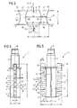
- FIG. 5 show a first embodiment of a treatment rotor 1 and parts thereof
- FIG. 6 A second embodiment of a treatment rotor.
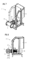
- FIGS. 7 and 8 show a device 7 for treating sludge S, in particular biogenic sludge, (or possibly also a mixture of sludge S and flocculant F), in particular for mixing in flocculant F or disintegrating sludge S.
- the treatment rotor 1 in a T-shaped Section of a transport or feed line 9 shown only in sections for the sludge S is rotatably mounted. The treatment rotor 1 protrudes into the interior of the feed line.
- the treatment rotor 1 has an inner hollow rotor base body 2 with an inner space 20, which is enclosed by a substantially hollow cylindrical wall 21, and a plurality of treatment elements 4 projecting or projecting on the rotor base body 2 and projecting outwards, in particular in the radial direction R radial direction and 14 on.
- the treatment rotor 1 is rotatable about an axis of rotation R extending centrally through the treatment rotor 1 and for this purpose has a coupling element (connection shaft) 3 adjoining the rotor base body 2 axially of the rotation axis R, via which the treatment rotor 1 is provided with an in FIG. 1 Not shown rotary drive (10 in FIG. 6 and 7
- the rotation direction of the rotational movement of the treatment rotor 1 is denoted by T and is generally a direction tangent to a circle about the rotation axis R or one along a circle about the rotation axis R running and the circle curvature following the following direction. In the example of FIG. 1 If the direction of rotation T is selected clockwise, but may also be directed in the opposite or counterclockwise direction or to avoid a clogging of the treatment rotor 1 are also changed regularly.
- the treatment elements 4 and 14 are in particular designed as treatment pins or treatment teeth.
- the treatment rotor 1 offset on opposite sides by approximately 180 ° two parallel to the axis of rotation R extending rectilinear rows of substantially equal to each other, each example five, treatment elements 4 on one side and 14 on the other side.
- the treatment rotor 1 is used as a mixing rotor and its treatment elements are designed as mixing elements and their treatment edges as mixing edges.
- Such an application is preferably described here.
- the treatment rotor 1 is a disintegration rotor and its treatment elements are designed as disintegration elements and their treatment edges as disintegration edges.
- apertures 6 are provided in the wall 21 in the circumferential direction or in the direction of rotation T.
- the openings as in FIG. 1, 2 and 5 to see as parallel to the axis of rotation R extending axial slots are formed, but also designed differently or arranged or can be varied in number.
- the openings 6 are also mutually offset by about 180 ° and the treatment elements 4 and 14 each about 90 °. Through the openings 6, the interior 20 of the rotor base body 2 with the outside space in flow communication.
- FIG. 6 are additional outlet openings 55 in the boundary walls 50 seen axially between the treatment elements 4 and 14, which open directly into the interstices 5 and 15 and also connect the interior 20 of the rotor body 2 with the outside space.
- the treatment elements 4 are spaced or separated by gaps 5 and the treatment elements 14 by gaps 15. However, it is also possible for more than two such rows of spaced-apart treatment elements to be provided.
- the treatment elements 4 and 14 all protrude outwardly substantially radially with respect to the axis of rotation R and each have four preferably rectilinear treatment edges 41, 42, 43 and 44 which are parallel to a radial direction perpendicular to the axis of rotation R, substantially perpendicular to the direction of rotation T and parallel to each other to the outside and have substantially the same length L4.
- the inlet opening 51 and the outlet opening 52 can, as shown, the same size or an equal (flow) cross-sectional area, preferably also have the same shape, but may also be different.
- the two treatment edges 41 and 43 are connected by a flat side 47 of the treatment element 4 and 14, while between the treatment edges 42 and 44 a further flat side 47 parallel flat side 48 of the treatment element 4 and 14 is located.
- the opposite treatment edges 41 and 42 and 43 and 44 on the two flat sides 47 and 48 are connected by concave, ie inwardly curved side walls 45 and 46, which thus also form the lateral boundary walls of the intermediate spaces 5 and 15, respectively from the perspective of the spaces 5 and 15 so convex, ie outwards, are curved.
- the shape of the side walls 45 and 46 is in each case in particular mirror-symmetrical with respect to a symmetry plane lying in the middle between the two flat sides 47 and 48 and parallel thereto, for example cylindrical.
- the two side walls 45 and 46 are preferably also mirror-symmetrical with respect to one another in the middle between the two treatment edges 41 and 43 and to the flat sides 47 and 48 orthogonal plane of symmetry.
- the axial width of the treatment elements 4 and 14, measured parallel to the axis of rotation R or perpendicular to the direction of rotation T first increases inwardly from a maximum width L2 at the front on the flat side 47 to a minimum at the center of the treatment element 4 or 14 Width from and then back to a maximum width L2 back of the flat side 48 too.
- the axial width of the intermediate spaces 5 and 15 measured parallel to the axis of rotation R or in the direction of rotation T increases from a minimum width L3 at the front to the center of the intermediate space 5 or 15 to a maximum width and then back to the rear a minimum width L3 outside.
- FIG 3 This is especially good in FIG 3 to recognize where, by way of example, a greater width B1 of the treatment element 4 with a corresponding smaller width W1 of the intermediate space 5 and a smaller width B2 of the treatment element 4 further inside with an associated larger width W2 of the intermediate space 5 are shown.
- This (more general) teaching for the design of the treatment elements or spaces is also by other embodiments except those in 1 to 5 illustrated, for example, by another design of their cross sections with different curved and / or asymmetric side walls 45 and 46 and other axial widths or widths.
- only one side wall 45 or 46 may be concave and the other flat or even convex.
- the outer surface of the treatment elements 4 and 14, which connects the end points of the treatment edges 41 to 44, is designated by 49 and is preferably designed as a flat side.
- the inner boundary walls of the intermediate spaces 5 and 15 are designated 50 and preferably also formed flat.
- treatment elements 7 and 17 are spaced from the adjacent first treatment element 4 and 14, however, which are curved at the end face to the rear Treatment rotor 1 better transverse to a pipe cross-section of a flow pipe for the mud S to fit. Due to the beveled or curved shaping beforehand, the treatment rotor 1 can be adapted to the curved inner walls of the tubular transport or feed line 9 and transversely to the longitudinal direction of the feed line 9, ie the transport direction of the sludge S, as far as possible into the feed line, without strike the treatment elements on rotation of the treatment rotor 1 on the inner walls, or touch them.
- the treatment elements or the treatment rotor 1 may vary according to the particular shape of the feed line.
- the treatment elements 4 and 14 may have substantially the same shape.
- At the rear ends of the two rows of treatment elements 4 and 14 is at a distance from the adjacent last treatment element 4 and 14 fastener 8 and 18 for attaching the treatment rotor 1 to a co-rotating part of a mechanical seal, not shown.
- the depth of the intermediate spaces 5 and 15 corresponds to the length L4 of the treatment edges 41 to 44.
- the space between the fastening element 8 or 18 and treatment element 4 or 14 is less deep with depth L8 for reasons of stability.
- the treatment elements 4 and 14 and 7 and 17 are preferably in pairs at the same axial positions along the axis of rotation R, as well as the fasteners 8 and 18. This is achieved in particular in an embodiment in which the treatment rotor 1 has a symmetry with respect to a rotation through 180 ° having. In one embodiment with three or four or generally n rows of treatment elements instead of only two, this rotational symmetry is then to be formed with respect to 120 ° or 90 ° or in general 360 ° / n.
- the total length of the two lateral rows of treatment elements 17 and 4 or 7 and 14 on the one hand and fastener 8 or 18 is denoted by L6.
- the outer diameter of the treatment rotor 1 between the outer sides of the two rows, corresponding to the outer surfaces 49 of the treatment elements 4 and 14, is denoted by L5.
- L7 is the diameter of the main body 2, so its (maximum) dimension is perpendicular to the axis of rotation R.
- L1 to L7 can be chosen without loss of generality: L1 between 6 mm and 28 mm, L2 between 3 mm and 17 mm, L3 between 2 mm and 14 mm, L4 between 12 mm and 220 mm, L5 between 80 mm and 510 mm, L6 between 88 mm and 530 mm and L7 between 21 mm and 270 mm.
- the mode of operation of the treatment rotor 1 can be described as follows:
- a flocculant F passed through or flowing through the interior space 20, as best shown in FIG. 2 can be seen, introduced through the apertures 6 substantially radially away from the axis of rotation R outwards into the sludge S located in the outer space.
- the mixture or mixture of sludge S and flocculant F is designated S + F.
- the flocculant F is used in a known manner and already described above for conditioning the sludge S, in particular for improving the efficiency in a subsequent mechanical liquid withdrawal, in particular dewatering, in particular by means of a press or centrifuge or a water-permeable textile bag or the like.
- the flocculant F introduced via the apertures 6 into the sludge S is then mixed further into the sludge S from the respective next and possibly following treatment element (s) 4 or 14 with treatment energy input and with a better degree of treatment.
- the sludge-flocculant mixture S + F is pressed or guided in a direction opposite to the direction of rotation T flow direction through the interstices 5 between the treatment elements 4 (or intermediate spaces 15 between the treatment elements 14), such as good at FIG. 3 to see.
- the mixture S + F enters through the inlet opening 51, which lies between the front in the direction of rotation T treatment edges 41 and 43 of the adjacent treatment elements 4, in the intermediate space 5 and thereby flows past these front treatment edges 41 and 43.
- the front treatment edges 41 and 43 operate or act as swirling and tear-off edges for the flow of the mud-flocculant mixture S + F.
- the mixture is now not pressed out or thrown outwards due to the centrifugal forces, but, in the case of the treatment rotor 1 according to the invention, forcedly initially remains on the treatment rotor 1.
- the mixture S + F of sludge S and flocculant F is pressed or guided through the gap 5, and flows out of the gap 5 only at the exit port 52.
- the mixture S + F also flows in forced flow past the second pair of opposing treatment edges 42 and 44 at the outlet opening 52 and is once again subjected to mixing energy and swirled by them.
- the number of effective or on the same volume of the mud-flocculant mixture S + F acting treatment edges is increased by four according to a first effect of the invention by four, namely the four adjacent to the gap 5 (or 15) treatment edges 41 to 44 of the adjacent treatment elements 4 (or 14).
- an effective edge length of the treatment edges is obtained or swirl edges of 4 L4 per gap 5 or 15 and 4 L8 in the last two spaces.
- the total edge length would be 40 L4 + 8 L8.
- This increased treatment edge number or length according to the invention results in a significant improvement of the treatment result or the mixing energy input.
- a second effect results from the change of the flow cross-section in the gap 5 (or 15) for the mixture S + F flowing through.
- the mixture S + F is decompressed first due to the initially increasing cross-section of the gap 5 (or 15) in the direction of flow, ie the static pressure is reduced due to the higher dynamic pressure, and subsequently due to the subsequently decreasing cross-section of the gap 5 (or 15). compressed. If the inlet opening 51 and the outlet opening 52 have substantially the same flow cross-section, so are the static pressures at the entrance and exit of the mixture S + F in and out of the gap 5 (or 15) is substantially equal.
- the mixture S + F is sucked into the interspaces 5 (15) by the pressure curve within the interspaces 5 (15) and does not deviate outwards before the rear treatment edges 42 and 44, but instead also flows over the rear treatment edges 42 and 44 at Exit from the spaces 5 (15) almost completely.
- the same volume element of the sludge-flocculant mixture S + F is thus guided past both the front treatment edges 41 and 43 and the rear treatment edges 42 and 44 and further vortexed and mixed.
- the said second effect is itself caused by the pressure differences, which may cause cavitation effects even beyond a certain size, such as in a cavitation nozzle, which improve the mixing of the mixture S + F also during the flow within the gap 5 (15) between the treatment edges ,
- the axial width of the treatment elements 4 and 14 increases in the direction of rotation T, the axial width of the treatment elements 4 and 14 from a minimum width B2 front of the flat side 47 to a maximum width B1 rear of the flat side 48 and accordingly in the direction of rotation T.
- the axial width of the intermediate spaces 5 and 15 decreases from a maximum width W2 in the front to a minimum width W1 at the rear.
- the inlet opening 51 of the intermediate spaces 5 and 15 in this embodiment is therefore always larger than the outlet opening 52 of the intermediate spaces 5 and 15.
- the sludge-flocculant mixture S + F is only compressed on its way through the intermediate spaces between the treatment elements and not decompressed first. Also in this embodiment good mixing results are achieved.
- treatment edges can also be provided only at the outlet opening 52, while at the inlet opening also blunt or curved and / or funnel-shaped inlet regions can be provided.
- the ratio B1 / B2 of the maximum axial width B1 to the minimum width B2 of the treatment elements 4 and 14 is preferably greater than 2, preferably between 2 and 3.5.
- the ratio W2 / W1 of the maximum axial width W2 to the minimum width W1 of the interstices 5 and 15 is preferably greater than 1.4, preferably between 1.5 and 2.8, selected.
- These ratios B1 / B2 or W2 / W1 are a measure of the relative decrease or increase in the axial width of the treatment elements or the axial width of the spaces between the treatment elements and thus also determine the degree of compression (or decompression, if necessary) of the sludge flocculant Mixture S + F.
- the gaps 5 and 15 may also be completed radially outward to prevent squeezing out of the sludge-flocculant mixture S + F due to the centrifugal forces.
- the longitudinal part may again treatment edges, in particular axially extending treatment edges on the outside, and in particular be designed as a square or square tube, which is applied from the outside to the outer surfaces of the treatment elements, for example by welding.
- a reversing function or a reversing operation for cleaning the gaps 5 and 15 may be provided, in which the rotor is rotated in the opposite direction to the provided in mixing operation direction of rotation T, especially to remove larger particles from the spaces.
- the treatment edges 41 to 44 are preferably formed sharp-edged, in order to achieve a good turbulence.
- the surface of the treatment rotor 1 can be provided at least at the treatment edges with a wear protection layer, e.g. a layer produced by plasma nitriding or a ceramic coating, in particular an aluminum oxide layer, for example by spraying, or else a hard material layer, e.g. be provided a TiN or TiCN layer.
- the treatment elements 4 and 14 may be integrally connected to each other and / or with the base body or inserted as prefabricated parts in openings in the body and inserted into the interior and then fastened by means of screws and / or transverse pins.
- FIGS. 7 and 8 is to rotate the treatment rotor 1 in the feed line 9 of this, z. B. non-positively coupled via the coupling element 3 with a motor 10.
- sludge S is pumped or guided through the feed line 9 while the treatment rotor 1 is rotated by the motor 10.
- flocculant is supplied by the treatment rotor 1.
- the treatment rotor 1 is preferably completely surrounded by sludge S, which is particularly advantageous with regard to the treatment efficiency.
- the cross-sectional area claimed by the treatment rotor 1, which corresponds in particular to the product L5 ⁇ L6 in the illustrated embodiment, is greater than 50% and less than 74% of the flow cross-sectional area of the feed line section of the feed line 9, in which the treatment rotor 1 is arranged ,
- sealing elements can be provided to seal the coupling element 3 against the feed line 9 against the passage of sludge S or liquid.
- a Control unit for the motor 10 and the non-illustrated (s) for the flocculant F and preferably also the sludge S is denoted by 11.
- the speed of the treatment rotor 1 can advantageously between 1200 and 4000 rev / min. can be selected, the sludge volume flow in the feed line 9 may typically be from 3 to 400 m 3 per hour.
- the apparatus 7 may be downstream of a drying device, not shown, in particular, a filter press or a centrifuge for drying or dewatering of the sludge S in the flow direction or transport direction of the sludge S, wherein the flocculant F remains largely in the separated water or liquid.
- FIGS. 7 and 8 Device shown can also further, the treatment rotor 1 shown upstream or downstream or also connected in parallel specialistssgrunsgrotoren 1, which can be integrated analogously to the manner described above in the feed line 9.
- the operation and design of the treatment rotor 1 can remain substantially the same.
- the disintegration effect is greatly improved by the design of the treatment rotor according to the invention, in particular the described Verwirbelungs- and compression and decompression, analogous to the interference effect.
- the breakthroughs 6 can serve here for the passage of sludge S or omitted altogether.
Landscapes
- Chemical & Material Sciences (AREA)
- Chemical Kinetics & Catalysis (AREA)
- Life Sciences & Earth Sciences (AREA)
- Hydrology & Water Resources (AREA)
- Engineering & Computer Science (AREA)
- Environmental & Geological Engineering (AREA)
- Water Supply & Treatment (AREA)
- Organic Chemistry (AREA)
- General Chemical & Material Sciences (AREA)
- Treatment Of Sludge (AREA)
- Mixers Of The Rotary Stirring Type (AREA)
- Crushing And Grinding (AREA)
Priority Applications (1)
| Application Number | Priority Date | Filing Date | Title |
|---|---|---|---|
| PL11727417T PL2582452T3 (pl) | 2010-06-15 | 2011-06-09 | Urządzenie i sposób przetwarzania osadów |
Applications Claiming Priority (2)
| Application Number | Priority Date | Filing Date | Title |
|---|---|---|---|
| DE102010023793A DE102010023793A1 (de) | 2010-06-15 | 2010-06-15 | Vorrichtung und Verfahren zum Einmischen von Konditioniermittel, insbesondere Flockmittel, in Schlämme |
| PCT/EP2011/059620 WO2011157633A2 (de) | 2010-06-15 | 2011-06-09 | Vorrichtung und verfahren zum behandeln von schlämmen |
Publications (2)
| Publication Number | Publication Date |
|---|---|
| EP2582452A2 EP2582452A2 (de) | 2013-04-24 |
| EP2582452B1 true EP2582452B1 (de) | 2015-05-13 |
Family
ID=44359810
Family Applications (1)
| Application Number | Title | Priority Date | Filing Date |
|---|---|---|---|
| EP20110727417 Active EP2582452B1 (de) | 2010-06-15 | 2011-06-09 | Vorrichtung und verfahren zum behandeln von schlämmen |
Country Status (9)
| Country | Link |
|---|---|
| US (2) | US9289705B2 (pl) |
| EP (1) | EP2582452B1 (pl) |
| KR (1) | KR101700006B1 (pl) |
| CA (1) | CA2800924C (pl) |
| DE (1) | DE102010023793A1 (pl) |
| DK (1) | DK2582452T3 (pl) |
| ES (1) | ES2545128T3 (pl) |
| PL (1) | PL2582452T3 (pl) |
| WO (1) | WO2011157633A2 (pl) |
Families Citing this family (9)
| Publication number | Priority date | Publication date | Assignee | Title |
|---|---|---|---|---|
| US6912626B1 (en) * | 2000-08-31 | 2005-06-28 | Micron Technology, Inc. | Method and apparatus for connecting a massively parallel processor array to a memory array in a bit serial manner |
| DE102010023793A1 (de) | 2010-06-15 | 2011-12-15 | J. F. Knauer Industrie-Elektronik Gmbh | Vorrichtung und Verfahren zum Einmischen von Konditioniermittel, insbesondere Flockmittel, in Schlämme |
| KR101040927B1 (ko) | 2011-03-30 | 2011-06-16 | (주)플록마스터 | 슬러지 파쇄용 믹스장치 |
| CA2937341C (en) * | 2015-07-28 | 2023-10-03 | Douglas G. Pullman | Mixing apparatus and system |
| CN107915346B (zh) * | 2017-11-20 | 2020-01-10 | 哈尔滨商业大学 | 一种中心混合-同心圆扇形廊道网格絮凝-扇形斜管沉淀一体化装置 |
| IT201800010289A1 (it) * | 2018-11-13 | 2020-05-13 | Tt Italy S P A | Testa di miscelazione |
| EP3898498B1 (en) | 2018-12-20 | 2025-02-19 | The Coca-Cola Company | Dispensing nozzle assemblies with static mixers |
| WO2020227271A1 (en) | 2019-05-08 | 2020-11-12 | The Coca-Cola Company | Dispensing nozzle assemblies with static mixers |
| CN113731210B (zh) * | 2021-09-24 | 2024-09-10 | 智涂机器人(深圳)有限公司 | 一种混合器、混合装置及设计方法 |
Family Cites Families (30)
| Publication number | Priority date | Publication date | Assignee | Title |
|---|---|---|---|---|
| DE74618C (de) * | TH. GROKE in Merseburg, Halleschestrafse 26 | Keilförmiges Treibmesser an Mischmaschinen für pulverförmiges und körniges Gut | ||
| US2592709A (en) * | 1950-02-25 | 1952-04-15 | Universal Oil Prod Co | Mixing and homogenizing apparatus |
| JPS6259132U (pl) * | 1985-10-02 | 1987-04-13 | ||
| DE3719441A1 (de) | 1987-06-11 | 1988-12-22 | Kupczik Guenter | Verfahren zur zerlegung von verklammerten organischen und mineralischen bestandteilen in suspensionen, wie schlaemmen und abwaessern, und vorrichtung zur durchfuehrung des verfahrens |
| JPH09117654A (ja) * | 1995-10-24 | 1997-05-06 | Ishikawajima Harima Heavy Ind Co Ltd | 攪拌槽の洗浄装置 |
| DE19613679A1 (de) * | 1996-04-05 | 1997-10-09 | Lobbe Xenex Gmbh | Verfahren und Vorrichtung zur Konditionierung von feuchtem oder nassem Gelände, insbesondere von Schlammbecken |
| JP2002506387A (ja) | 1997-06-24 | 2002-02-26 | キャディ インターナショナル | 懸濁液の沈殿物分解並びに固形物の分離装置及び方法 |
| US6350054B1 (en) * | 1997-12-08 | 2002-02-26 | Bp Corporation North America Inc. | Agitator for a horizontal polymerization reactor having contiguous paddle stations with paddles and sub-stations with sub-station paddles |
| DE19808156A1 (de) | 1998-02-27 | 1999-09-02 | Knauer | Vorrichtung zum Aufbereiten von Konditioniermittel für wäßrigen Schlamm |
| DE19919521A1 (de) * | 1999-04-29 | 2000-11-02 | Micafil Ag Zuerich | Vorrichtung zum Mischen und Entgasen einer fliessfähigen Masse |
| ATE273065T1 (de) * | 1999-11-12 | 2004-08-15 | Kettenbach Gmbh & Co Kg | Vorrichtung zum vermischen zweier pastöser massen,insbesondere zum vermischen einer dental- abformmasse mit einer katalysatormasse |
| US6443612B1 (en) * | 1999-12-02 | 2002-09-03 | Wilhelm A. Keller | Dynamic mixer |
| JP2002248493A (ja) | 2001-02-27 | 2002-09-03 | Torishima Pump Mfg Co Ltd | 汚泥処理装置 |
| US6499727B1 (en) | 2001-06-15 | 2002-12-31 | Jack Bill Sylvester | Internal drive aerator for body of liquids |
| US6808305B2 (en) * | 2002-03-25 | 2004-10-26 | Sharpe Mixers, Inc. | Method and apparatus for mixing additives with sludge in a powered line blender |
| JP2004130181A (ja) * | 2002-10-09 | 2004-04-30 | Asahi Recycle Support Kk | 有機廃棄物の処理装置における攪拌装置 |
| DE10310091A1 (de) * | 2003-03-06 | 2004-09-16 | Abb Lummus Global Gmbh | Segmentierter Rührreaktor |
| DE10335552B4 (de) * | 2003-08-02 | 2005-07-28 | Stephan Machinery Gmbh & Co. | Mischwelle zur Durchmischung und Zerteilung von Lebensmittelprodukten sowie Verfahren zur Herstellung eines Überzugs für eine derartige Mischwelle |
| EP1510248B1 (en) * | 2003-08-14 | 2005-06-08 | 3M Espe Ag | Mixer element for a mixer for multi-component pastes, and mixer using the same |
| DE202005000875U1 (de) | 2005-01-20 | 2006-06-01 | BIONIK GmbH - Innovative Technik für die Umwelt | Vorrichtung zum Zerkleinern partikulärer organischer Substanzen in Suspensionen von Mikroorganismen in einem Trägermedium, insbesondere in Abwässern |
| DE102005019010A1 (de) * | 2005-04-22 | 2006-10-26 | Maschinenfabrik Gustav Eirich Gmbh & Co. Kg | Mischflügel mit lösbarem Verschleißelement |
| JP4861899B2 (ja) * | 2006-06-02 | 2012-01-25 | Dic株式会社 | C.i.ピグメントレッド57:1及びその製造方法 |
| JP2009039683A (ja) * | 2007-08-10 | 2009-02-26 | Toyo Manufacturing Co Ltd | 濁水処理装置 |
| DE102008017045B9 (de) * | 2008-04-03 | 2012-07-05 | Umicore Ag & Co. Kg | Rührsystem und Verfahren zum Homogenisieren von Glasschmelzen |
| WO2010082391A1 (ja) * | 2009-01-16 | 2010-07-22 | Dic株式会社 | 撹拌装置及び撹拌方法 |
| KR200447694Y1 (ko) | 2009-06-02 | 2010-02-11 | (주)동방엔지니어링 | 수분을 함유한 폐기물 처리장치용 스크류 |
| SG178021A1 (en) * | 2009-08-21 | 2012-03-29 | Umicore Ag & Co Kg | Mixing apparatus |
| DE102010023793A1 (de) | 2010-06-15 | 2011-12-15 | J. F. Knauer Industrie-Elektronik Gmbh | Vorrichtung und Verfahren zum Einmischen von Konditioniermittel, insbesondere Flockmittel, in Schlämme |
| EP2399666B1 (en) * | 2010-06-22 | 2013-02-20 | 3M Innovative Properties Company | Mixer for preparing a dental material, and system comprising the same |
| KR101291949B1 (ko) * | 2011-11-18 | 2013-07-31 | 아반스트레이트 가부시키가이샤 | 유리의 제조 방법 및 교반 장치 |
-
2010
- 2010-06-15 DE DE102010023793A patent/DE102010023793A1/de not_active Withdrawn
-
2011
- 2011-06-09 WO PCT/EP2011/059620 patent/WO2011157633A2/de not_active Ceased
- 2011-06-09 CA CA2800924A patent/CA2800924C/en active Active
- 2011-06-09 KR KR1020137001002A patent/KR101700006B1/ko active Active
- 2011-06-09 EP EP20110727417 patent/EP2582452B1/de active Active
- 2011-06-09 PL PL11727417T patent/PL2582452T3/pl unknown
- 2011-06-09 DK DK11727417.5T patent/DK2582452T3/en active
- 2011-06-09 ES ES11727417.5T patent/ES2545128T3/es active Active
-
2012
- 2012-12-14 US US13/715,373 patent/US9289705B2/en active Active
-
2016
- 2016-01-18 US US14/997,646 patent/US10227248B2/en active Active
Also Published As
| Publication number | Publication date |
|---|---|
| WO2011157633A2 (de) | 2011-12-22 |
| PL2582452T3 (pl) | 2016-01-29 |
| US20160130167A1 (en) | 2016-05-12 |
| US10227248B2 (en) | 2019-03-12 |
| DE102010023793A1 (de) | 2011-12-15 |
| WO2011157633A3 (de) | 2012-05-10 |
| KR20130108242A (ko) | 2013-10-02 |
| KR101700006B1 (ko) | 2017-02-13 |
| EP2582452A2 (de) | 2013-04-24 |
| US9289705B2 (en) | 2016-03-22 |
| US20130098843A1 (en) | 2013-04-25 |
| CA2800924C (en) | 2018-03-06 |
| CA2800924A1 (en) | 2011-12-22 |
| DK2582452T3 (en) | 2015-08-24 |
| ES2545128T3 (es) | 2015-09-08 |
Similar Documents
| Publication | Publication Date | Title |
|---|---|---|
| EP2582452B1 (de) | Vorrichtung und verfahren zum behandeln von schlämmen | |
| WO2009065509A1 (de) | Verfahren und vorrichtung zum behandeln von schlamm | |
| DE102005037026B4 (de) | Kavitationsmischer | |
| WO2001080985A1 (de) | Statisches mischelement | |
| DE202016000169U1 (de) | Pump- und/oder Mischeinrichtung zum Fördern, Homogenisieren und/oder Dispergieren fließfähiger Produkte | |
| EP2403632A1 (de) | Zerkleinerungs- und dispergiervorrichtung | |
| EP3102332A1 (de) | Rührwerkskugelmühle | |
| DE602005003356T2 (de) | Verfahren, vorrichtung und rotor zur homogenisierung eines mediums | |
| EP1896184A2 (de) | Verfahren und vorrichtung zur erzaufbereitung | |
| DE10343602A1 (de) | Vorrichtung und Verfahren zur Behandlung eines Mediums wie Abwasser, Klärschlamm oder dergleichen | |
| DE102004051063A1 (de) | Innenmischer zum Kneten von plastischen Massen | |
| WO2017129419A1 (de) | Vorrichtung und verfahren zur flokkulation von feststoffanteilen eines fest-fluessig-gemisches | |
| DE102007005622A1 (de) | Vorrichtung und Verfahren zur kontinuierlichen Herstellung einer Mischung aus wenigstens zwei fließfähigen Phasen | |
| EP2624943B1 (de) | Vorrichtung zur behandlung einer flüssigkeit und verfahren zum behandeln einer suspension | |
| EP3652114B1 (de) | Verfahren und vorrichtung zur behandlung von schadstoffen im wasser durch kavitation | |
| EP1771385B1 (de) | Hydrodynamische homogenisation | |
| WO2009062654A1 (de) | Verfahren und vorrichtung zum behandeln eines biogenen schlammes, insbesondere eines klärschlammes | |
| DE102006016067B3 (de) | Flockenformeinrichtung | |
| DE202005018432U1 (de) | Homogenisator-Vorrichtung mit gegenläufig rotierbaren Zahnkränzen | |
| DE102012016998B3 (de) | Mischvorrichtung | |
| EP3253554B1 (de) | Stopfschnecke | |
| DE3100909A1 (de) | Behandlungsgefaess zur chemisch-mechanischen wasseraufbereitung | |
| EP3922609A1 (de) | Walzenbaugruppe, insbesondere zur wasseraufbearbeitung, und aufbereitungsvorrichtung | |
| DE202015101484U1 (de) | Schneckenpressenvorrichtung | |
| DE3627428C2 (pl) |
Legal Events
| Date | Code | Title | Description |
|---|---|---|---|
| PUAI | Public reference made under article 153(3) epc to a published international application that has entered the european phase |
Free format text: ORIGINAL CODE: 0009012 |
|
| 17P | Request for examination filed |
Effective date: 20121121 |
|
| AK | Designated contracting states |
Kind code of ref document: A2 Designated state(s): AL AT BE BG CH CY CZ DE DK EE ES FI FR GB GR HR HU IE IS IT LI LT LU LV MC MK MT NL NO PL PT RO RS SE SI SK SM TR |
|
| DAX | Request for extension of the european patent (deleted) | ||
| 17Q | First examination report despatched |
Effective date: 20140226 |
|
| RIC1 | Information provided on ipc code assigned before grant |
Ipc: B01F 7/00 20060101AFI20141121BHEP Ipc: C02F 11/14 20060101ALI20141121BHEP |
|
| GRAP | Despatch of communication of intention to grant a patent |
Free format text: ORIGINAL CODE: EPIDOSNIGR1 |
|
| INTG | Intention to grant announced |
Effective date: 20150109 |
|
| GRAS | Grant fee paid |
Free format text: ORIGINAL CODE: EPIDOSNIGR3 |
|
| GRAA | (expected) grant |
Free format text: ORIGINAL CODE: 0009210 |
|
| AK | Designated contracting states |
Kind code of ref document: B1 Designated state(s): AL AT BE BG CH CY CZ DE DK EE ES FI FR GB GR HR HU IE IS IT LI LT LU LV MC MK MT NL NO PL PT RO RS SE SI SK SM TR |
|
| REG | Reference to a national code |
Ref country code: GB Ref legal event code: FG4D Free format text: NOT ENGLISH |
|
| REG | Reference to a national code |
Ref country code: CH Ref legal event code: EP |
|
| REG | Reference to a national code |
Ref country code: IE Ref legal event code: FG4D Free format text: LANGUAGE OF EP DOCUMENT: GERMAN |
|
| REG | Reference to a national code |
Ref country code: AT Ref legal event code: REF Ref document number: 726608 Country of ref document: AT Kind code of ref document: T Effective date: 20150615 |
|
| REG | Reference to a national code |
Ref country code: DE Ref legal event code: R096 Ref document number: 502011006837 Country of ref document: DE Effective date: 20150625 |
|
| REG | Reference to a national code |
Ref country code: DK Ref legal event code: T3 Effective date: 20150817 |
|
| REG | Reference to a national code |
Ref country code: NL Ref legal event code: T3 |
|
| REG | Reference to a national code |
Ref country code: SE Ref legal event code: TRGR |
|
| REG | Reference to a national code |
Ref country code: ES Ref legal event code: FG2A Ref document number: 2545128 Country of ref document: ES Kind code of ref document: T3 Effective date: 20150908 Ref country code: FR Ref legal event code: PLFP Year of fee payment: 5 |
|
| REG | Reference to a national code |
Ref country code: DE Ref legal event code: R082 Ref document number: 502011006837 Country of ref document: DE Representative=s name: MICHALSKI HUETTERMANN & PARTNER PATENTANWAELTE, DE Ref country code: DE Ref legal event code: R081 Ref document number: 502011006837 Country of ref document: DE Owner name: ECOLAB USA INC. (N.D.GES.D.STAATES DELAWARE), , US Free format text: FORMER OWNER: J. F. KNAUER INDUSTRIE-ELEKTRONIK GMBH, 60437 FRANKFURT, DE |
|
| REG | Reference to a national code |
Ref country code: NO Ref legal event code: T2 Effective date: 20150513 Ref country code: LT Ref legal event code: MG4D |
|
| PG25 | Lapsed in a contracting state [announced via postgrant information from national office to epo] |
Ref country code: HR Free format text: LAPSE BECAUSE OF FAILURE TO SUBMIT A TRANSLATION OF THE DESCRIPTION OR TO PAY THE FEE WITHIN THE PRESCRIBED TIME-LIMIT Effective date: 20150513 Ref country code: PT Free format text: LAPSE BECAUSE OF FAILURE TO SUBMIT A TRANSLATION OF THE DESCRIPTION OR TO PAY THE FEE WITHIN THE PRESCRIBED TIME-LIMIT Effective date: 20150914 Ref country code: LT Free format text: LAPSE BECAUSE OF FAILURE TO SUBMIT A TRANSLATION OF THE DESCRIPTION OR TO PAY THE FEE WITHIN THE PRESCRIBED TIME-LIMIT Effective date: 20150513 |
|
| PG25 | Lapsed in a contracting state [announced via postgrant information from national office to epo] |
Ref country code: RS Free format text: LAPSE BECAUSE OF FAILURE TO SUBMIT A TRANSLATION OF THE DESCRIPTION OR TO PAY THE FEE WITHIN THE PRESCRIBED TIME-LIMIT Effective date: 20150513 Ref country code: LV Free format text: LAPSE BECAUSE OF FAILURE TO SUBMIT A TRANSLATION OF THE DESCRIPTION OR TO PAY THE FEE WITHIN THE PRESCRIBED TIME-LIMIT Effective date: 20150513 Ref country code: GR Free format text: LAPSE BECAUSE OF FAILURE TO SUBMIT A TRANSLATION OF THE DESCRIPTION OR TO PAY THE FEE WITHIN THE PRESCRIBED TIME-LIMIT Effective date: 20150814 Ref country code: BG Free format text: LAPSE BECAUSE OF FAILURE TO SUBMIT A TRANSLATION OF THE DESCRIPTION OR TO PAY THE FEE WITHIN THE PRESCRIBED TIME-LIMIT Effective date: 20150813 Ref country code: IS Free format text: LAPSE BECAUSE OF FAILURE TO SUBMIT A TRANSLATION OF THE DESCRIPTION OR TO PAY THE FEE WITHIN THE PRESCRIBED TIME-LIMIT Effective date: 20150913 |
|
| RAP2 | Party data changed (patent owner data changed or rights of a patent transferred) |
Owner name: ECOLAB USA INC. |
|
| PG25 | Lapsed in a contracting state [announced via postgrant information from national office to epo] |
Ref country code: EE Free format text: LAPSE BECAUSE OF FAILURE TO SUBMIT A TRANSLATION OF THE DESCRIPTION OR TO PAY THE FEE WITHIN THE PRESCRIBED TIME-LIMIT Effective date: 20150513 |
|
| REG | Reference to a national code |
Ref country code: DE Ref legal event code: R097 Ref document number: 502011006837 Country of ref document: DE |
|
| PG25 | Lapsed in a contracting state [announced via postgrant information from national office to epo] |
Ref country code: CZ Free format text: LAPSE BECAUSE OF FAILURE TO SUBMIT A TRANSLATION OF THE DESCRIPTION OR TO PAY THE FEE WITHIN THE PRESCRIBED TIME-LIMIT Effective date: 20150513 Ref country code: MC Free format text: LAPSE BECAUSE OF FAILURE TO SUBMIT A TRANSLATION OF THE DESCRIPTION OR TO PAY THE FEE WITHIN THE PRESCRIBED TIME-LIMIT Effective date: 20150513 Ref country code: SK Free format text: LAPSE BECAUSE OF FAILURE TO SUBMIT A TRANSLATION OF THE DESCRIPTION OR TO PAY THE FEE WITHIN THE PRESCRIBED TIME-LIMIT Effective date: 20150513 Ref country code: RO Free format text: LAPSE BECAUSE OF NON-PAYMENT OF DUE FEES Effective date: 20150513 |
|
| REG | Reference to a national code |
Ref country code: CH Ref legal event code: NV Representative=s name: WEINMANN ZIMMERLI, CH Ref country code: CH Ref legal event code: PUE Owner name: ECOLAB USA INC., US Free format text: FORMER OWNER: J.F. KNAUER INDUSTRIE-ELEKTRONIK GMBH, DE |
|
| PLBE | No opposition filed within time limit |
Free format text: ORIGINAL CODE: 0009261 |
|
| STAA | Information on the status of an ep patent application or granted ep patent |
Free format text: STATUS: NO OPPOSITION FILED WITHIN TIME LIMIT |
|
| REG | Reference to a national code |
Ref country code: GB Ref legal event code: 732E Free format text: REGISTERED BETWEEN 20160225 AND 20160302 |
|
| 26N | No opposition filed |
Effective date: 20160216 |
|
| REG | Reference to a national code |
Ref country code: FR Ref legal event code: PLFP Year of fee payment: 6 |
|
| PG25 | Lapsed in a contracting state [announced via postgrant information from national office to epo] |
Ref country code: SI Free format text: LAPSE BECAUSE OF FAILURE TO SUBMIT A TRANSLATION OF THE DESCRIPTION OR TO PAY THE FEE WITHIN THE PRESCRIBED TIME-LIMIT Effective date: 20150513 |
|
| REG | Reference to a national code |
Ref country code: AT Ref legal event code: PC Ref document number: 726608 Country of ref document: AT Kind code of ref document: T Owner name: ECOLAB USA INC., US Effective date: 20160615 |
|
| REG | Reference to a national code |
Ref country code: NL Ref legal event code: PD Owner name: ECOLAB USA INC.; US Free format text: DETAILS ASSIGNMENT: VERANDERING VAN EIGENAAR(S), OVERDRACHT; FORMER OWNER NAME: J.F. KNAUER INDUSTRIE-ELEKTRONIK GMBH Effective date: 20160606 |
|
| PG25 | Lapsed in a contracting state [announced via postgrant information from national office to epo] |
Ref country code: MT Free format text: LAPSE BECAUSE OF FAILURE TO SUBMIT A TRANSLATION OF THE DESCRIPTION OR TO PAY THE FEE WITHIN THE PRESCRIBED TIME-LIMIT Effective date: 20150513 |
|
| REG | Reference to a national code |
Ref country code: FR Ref legal event code: PLFP Year of fee payment: 7 |
|
| PG25 | Lapsed in a contracting state [announced via postgrant information from national office to epo] |
Ref country code: HU Free format text: LAPSE BECAUSE OF FAILURE TO SUBMIT A TRANSLATION OF THE DESCRIPTION OR TO PAY THE FEE WITHIN THE PRESCRIBED TIME-LIMIT; INVALID AB INITIO Effective date: 20110609 Ref country code: SM Free format text: LAPSE BECAUSE OF FAILURE TO SUBMIT A TRANSLATION OF THE DESCRIPTION OR TO PAY THE FEE WITHIN THE PRESCRIBED TIME-LIMIT Effective date: 20150513 |
|
| PG25 | Lapsed in a contracting state [announced via postgrant information from national office to epo] |
Ref country code: CY Free format text: LAPSE BECAUSE OF FAILURE TO SUBMIT A TRANSLATION OF THE DESCRIPTION OR TO PAY THE FEE WITHIN THE PRESCRIBED TIME-LIMIT Effective date: 20150513 |
|
| PG25 | Lapsed in a contracting state [announced via postgrant information from national office to epo] |
Ref country code: TR Free format text: LAPSE BECAUSE OF FAILURE TO SUBMIT A TRANSLATION OF THE DESCRIPTION OR TO PAY THE FEE WITHIN THE PRESCRIBED TIME-LIMIT Effective date: 20150513 |
|
| PG25 | Lapsed in a contracting state [announced via postgrant information from national office to epo] |
Ref country code: LU Free format text: LAPSE BECAUSE OF NON-PAYMENT OF DUE FEES Effective date: 20150609 |
|
| REG | Reference to a national code |
Ref country code: FR Ref legal event code: PLFP Year of fee payment: 8 |
|
| PG25 | Lapsed in a contracting state [announced via postgrant information from national office to epo] |
Ref country code: MK Free format text: LAPSE BECAUSE OF FAILURE TO SUBMIT A TRANSLATION OF THE DESCRIPTION OR TO PAY THE FEE WITHIN THE PRESCRIBED TIME-LIMIT Effective date: 20150513 |
|
| PG25 | Lapsed in a contracting state [announced via postgrant information from national office to epo] |
Ref country code: AL Free format text: LAPSE BECAUSE OF FAILURE TO SUBMIT A TRANSLATION OF THE DESCRIPTION OR TO PAY THE FEE WITHIN THE PRESCRIBED TIME-LIMIT Effective date: 20150513 |
|
| REG | Reference to a national code |
Ref country code: DE Ref legal event code: R079 Ref document number: 502011006837 Country of ref document: DE Free format text: PREVIOUS MAIN CLASS: B01F0007000000 Ipc: B01F0027000000 |
|
| REG | Reference to a national code |
Ref country code: FR Ref legal event code: PLFP Year of fee payment: 13 |
|
| PGFP | Annual fee paid to national office [announced via postgrant information from national office to epo] |
Ref country code: SE Payment date: 20250310 Year of fee payment: 15 |
|
| PGFP | Annual fee paid to national office [announced via postgrant information from national office to epo] |
Ref country code: NL Payment date: 20250409 Year of fee payment: 15 |
|
| PGFP | Annual fee paid to national office [announced via postgrant information from national office to epo] |
Ref country code: FI Payment date: 20250620 Year of fee payment: 15 |
|
| PGFP | Annual fee paid to national office [announced via postgrant information from national office to epo] |
Ref country code: PL Payment date: 20250409 Year of fee payment: 15 Ref country code: DE Payment date: 20250402 Year of fee payment: 15 |
|
| PGFP | Annual fee paid to national office [announced via postgrant information from national office to epo] |
Ref country code: GB Payment date: 20250401 Year of fee payment: 15 Ref country code: DK Payment date: 20250618 Year of fee payment: 15 |
|
| PGFP | Annual fee paid to national office [announced via postgrant information from national office to epo] |
Ref country code: NO Payment date: 20250610 Year of fee payment: 15 |
|
| PGFP | Annual fee paid to national office [announced via postgrant information from national office to epo] |
Ref country code: BE Payment date: 20250410 Year of fee payment: 15 Ref country code: IT Payment date: 20250522 Year of fee payment: 15 |
|
| PGFP | Annual fee paid to national office [announced via postgrant information from national office to epo] |
Ref country code: FR Payment date: 20250401 Year of fee payment: 15 |
|
| PGFP | Annual fee paid to national office [announced via postgrant information from national office to epo] |
Ref country code: AT Payment date: 20250528 Year of fee payment: 15 |
|
| PGFP | Annual fee paid to national office [announced via postgrant information from national office to epo] |
Ref country code: IE Payment date: 20250402 Year of fee payment: 15 |
|
| PGFP | Annual fee paid to national office [announced via postgrant information from national office to epo] |
Ref country code: ES Payment date: 20250703 Year of fee payment: 15 |
|
| PGFP | Annual fee paid to national office [announced via postgrant information from national office to epo] |
Ref country code: CH Payment date: 20250701 Year of fee payment: 15 |