EP2582452B1 - Apparatus and method for treating slurries - Google Patents
Apparatus and method for treating slurries Download PDFInfo
- Publication number
- EP2582452B1 EP2582452B1 EP20110727417 EP11727417A EP2582452B1 EP 2582452 B1 EP2582452 B1 EP 2582452B1 EP 20110727417 EP20110727417 EP 20110727417 EP 11727417 A EP11727417 A EP 11727417A EP 2582452 B1 EP2582452 B1 EP 2582452B1
- Authority
- EP
- European Patent Office
- Prior art keywords
- treatment
- rotation
- rotor
- axis
- elements
- Prior art date
- Legal status (The legal status is an assumption and is not a legal conclusion. Google has not performed a legal analysis and makes no representation as to the accuracy of the status listed.)
- Active
Links
Images


Classifications
-
- C—CHEMISTRY; METALLURGY
- C02—TREATMENT OF WATER, WASTE WATER, SEWAGE, OR SLUDGE
- C02F—TREATMENT OF WATER, WASTE WATER, SEWAGE, OR SLUDGE
- C02F11/00—Treatment of sludge; Devices therefor
-
- C—CHEMISTRY; METALLURGY
- C02—TREATMENT OF WATER, WASTE WATER, SEWAGE, OR SLUDGE
- C02F—TREATMENT OF WATER, WASTE WATER, SEWAGE, OR SLUDGE
- C02F11/00—Treatment of sludge; Devices therefor
- C02F11/12—Treatment of sludge; Devices therefor by de-watering, drying or thickening
- C02F11/14—Treatment of sludge; Devices therefor by de-watering, drying or thickening with addition of chemical agents
-
- B—PERFORMING OPERATIONS; TRANSPORTING
- B01—PHYSICAL OR CHEMICAL PROCESSES OR APPARATUS IN GENERAL
- B01D—SEPARATION
- B01D37/00—Processes of filtration
- B01D37/03—Processes of filtration using flocculating agents
-
- B—PERFORMING OPERATIONS; TRANSPORTING
- B01—PHYSICAL OR CHEMICAL PROCESSES OR APPARATUS IN GENERAL
- B01F—MIXING, e.g. DISSOLVING, EMULSIFYING OR DISPERSING
- B01F27/00—Mixers with rotary stirring devices in fixed receptacles; Kneaders
-
- B—PERFORMING OPERATIONS; TRANSPORTING
- B01—PHYSICAL OR CHEMICAL PROCESSES OR APPARATUS IN GENERAL
- B01F—MIXING, e.g. DISSOLVING, EMULSIFYING OR DISPERSING
- B01F27/00—Mixers with rotary stirring devices in fixed receptacles; Kneaders
- B01F27/05—Stirrers
- B01F27/07—Stirrers characterised by their mounting on the shaft
- B01F27/072—Stirrers characterised by their mounting on the shaft characterised by the disposition of the stirrers with respect to the rotating axis
- B01F27/0722—Stirrers characterised by their mounting on the shaft characterised by the disposition of the stirrers with respect to the rotating axis perpendicular with respect to the rotating axis
-
- B—PERFORMING OPERATIONS; TRANSPORTING
- B01—PHYSICAL OR CHEMICAL PROCESSES OR APPARATUS IN GENERAL
- B01F—MIXING, e.g. DISSOLVING, EMULSIFYING OR DISPERSING
- B01F27/00—Mixers with rotary stirring devices in fixed receptacles; Kneaders
- B01F27/05—Stirrers
- B01F27/07—Stirrers characterised by their mounting on the shaft
- B01F27/072—Stirrers characterised by their mounting on the shaft characterised by the disposition of the stirrers with respect to the rotating axis
- B01F27/0724—Stirrers characterised by their mounting on the shaft characterised by the disposition of the stirrers with respect to the rotating axis directly mounted on the rotating axis
-
- B—PERFORMING OPERATIONS; TRANSPORTING
- B01—PHYSICAL OR CHEMICAL PROCESSES OR APPARATUS IN GENERAL
- B01F—MIXING, e.g. DISSOLVING, EMULSIFYING OR DISPERSING
- B01F27/00—Mixers with rotary stirring devices in fixed receptacles; Kneaders
- B01F27/05—Stirrers
- B01F27/11—Stirrers characterised by the configuration of the stirrers
- B01F27/112—Stirrers characterised by the configuration of the stirrers with arms, paddles, vanes or blades
- B01F27/1125—Stirrers characterised by the configuration of the stirrers with arms, paddles, vanes or blades with vanes or blades extending parallel or oblique to the stirrer axis
-
- B—PERFORMING OPERATIONS; TRANSPORTING
- B01—PHYSICAL OR CHEMICAL PROCESSES OR APPARATUS IN GENERAL
- B01F—MIXING, e.g. DISSOLVING, EMULSIFYING OR DISPERSING
- B01F27/00—Mixers with rotary stirring devices in fixed receptacles; Kneaders
- B01F27/21—Mixers with rotary stirring devices in fixed receptacles; Kneaders characterised by their rotating shafts
- B01F27/2122—Hollow shafts
-
- C—CHEMISTRY; METALLURGY
- C02—TREATMENT OF WATER, WASTE WATER, SEWAGE, OR SLUDGE
- C02F—TREATMENT OF WATER, WASTE WATER, SEWAGE, OR SLUDGE
- C02F2303/00—Specific treatment goals
- C02F2303/26—Reducing the size of particles, liquid droplets or bubbles, e.g. by crushing, grinding, spraying, creation of microbubbles or nanobubbles
-
- Y—GENERAL TAGGING OF NEW TECHNOLOGICAL DEVELOPMENTS; GENERAL TAGGING OF CROSS-SECTIONAL TECHNOLOGIES SPANNING OVER SEVERAL SECTIONS OF THE IPC; TECHNICAL SUBJECTS COVERED BY FORMER USPC CROSS-REFERENCE ART COLLECTIONS [XRACs] AND DIGESTS
- Y02—TECHNOLOGIES OR APPLICATIONS FOR MITIGATION OR ADAPTATION AGAINST CLIMATE CHANGE
- Y02W—CLIMATE CHANGE MITIGATION TECHNOLOGIES RELATED TO WASTEWATER TREATMENT OR WASTE MANAGEMENT
- Y02W10/00—Technologies for wastewater treatment
- Y02W10/10—Biological treatment of water, waste water, or sewage
Definitions
- the invention relates to a device and a method in each case for treating sludges, in particular of industrial or biogenic origin.
- Such apparatus and methods find use in the treatment or remediation of sludges, particularly sludges of industrial origin, sludges from mining, sediment sludges in waters and / or even biogenic sludges.
- Biogenic sludges of animal or human origin are usually mixtures of liquid phase or liquid, usually mainly water, and solid phase or solid particles.
- the solid phase comprises biogenic particles or organic solids, cells and microorganisms, in particular bacteria, and aggregates thereof.
- biogenic sludges may include organic or inorganic matter as well as a gaseous phase, e.g. B. in the form of gas bubbles or dissolved gas.
- the gas may be from aerobic or anaerobic degradation of organic matter.
- Biogenic wastewater treatment sludges are also referred to as sewage sludge.
- sewage treatment sewage or dirty water usually comes after a mechanical pre-treatment in a primary clarifier, in which settle undissolved substances such as faeces and paper, etc. or float on the surface.
- Pre-clarified wastewater is then usually subjected to a biological treatment stage.
- organic substances in particular aerobically degraded by microorganisms, and partially oxidized inorganic substances.
- Typical processes for this biological stage are activated sludge processes with subsequent clarification.
- the activated sludge process uses biogenic ingredients the waste or dirty water by adding activated sludge, which z. B. contains flocculated aggregated bacteria, aerobically degraded aerobically under air supply biotics oxidative.
- the activated sludge sediments and is separated from the wastewater. Part of the sludge can be returned to the activated sludge process as so-called return sludge, in order to keep the concentration of the microorganisms sufficiently high.
- the excess sludge caused by biomass growth in the final clarification is thickened for further treatment together with the primary sludge of the primary treatment and then z. B. in digestion towers anaerobically further degraded. Resulting digested sludge is fed after passing through a Nacheindickers a sludge press for drainage and can be disposed of after dewatering. Clarification processes can also be carried out without primary treatment. In this case, only the excess sludge from the secondary clarification via a pre-thickener, usually without digester, fed to the sludge press.
- sludges for dewatering sludges, in particular sewage or industrial sludges or sediment sludges, it is known to separate the substantially water-containing liquid fraction of the sludge with a filter system or a centrifuge, at the same time solid components are separated from the sludge. Furthermore, drainage with bags or hoses made of (geo) textile filter materials are known.
- the sludge is now usually before dewatering a flocculant (flocculant) containing polymers, added to increase the degree of dewatering or the degree of drying of the sludge, so to better drain the sludge.
- the mode of action of the flocculant can be thought of as the polymers binding the particulate matter in the sludge in flakes or flocculation and thereby assisting or improving their separation from the water.
- the filtered dehydrated dry matter is also used as a filter cake designated.
- the polymers also improve the passage of water through the filter cake at the subsequent sludge levels.
- a device for conditioning conditioner (flocculant) for aqueous sludge known with a rotating distributor head for mixing a mixture of active ingredient stock solution and make-up water in a mixing chamber and a Impf diagnosed that mixed in the mixing agent solution as a conditioning agent to the in a delivery pipe gives off flowing watery mud.
- the distributor head has distributed about its axis of rotation substantially two parallel to the axis of rotation extending longitudinal slots as fluid outlets for the mixture and two radially outwardly and along the axis of rotation extending as a strip mixing blades on.
- the longitudinal slots are arranged in the circumferential direction between the mixing blades.
- the mixture flows through a shaft of the distributor head and through the slit-shaped fluid outlets to the outside into the mixing chamber where it is mixed by the two mixing blades.
- the mixing vanes have on their outer circumference or radially outermost region in a first embodiment parallel to the axis of rotation extending interference and axially front and rear subsequent curved inwardly extending end edges or in a second embodiment circular in a longitudinal axis containing the axis of rotation extending interference edges.
- the mixing edges of the mixing blades swirl and mix the flocculant introduced through the slots in the mud.
- the speed of the distributor head is set in a range between 700 rpm (revolutions per minute) and 2,500 rpm.
- the effectiveness of the biological treatment stage in sewage treatment plants can be increased by using homogenizers or disintegrators for treating the sewage sludge, in particular the return sludge, primary sludge or excess sludge and also the digested sludge.
- a disintegration rotor for sewage sludge is for example from the DE 37 19 441 A1 known.
- the known disintegration rotor has twisted wings with a curved front. A rotation of the disintegration rotor in the mud leads to disintegrating cavitation effects.
- the US 6,402,065 B1 discloses a disintegration rotor with vanes arranged parallel to the axis of rotation, in which the mud flows radially.
- a disintegration rotor in which the sludge is guided radially from inside to outside through partially nozzle-like cavities.
- the DE 74 618 C discloses a wedge-shaped driving or transport knife on mixing machines for powdery and granular material, which in addition to the feed of the material in the direction of the axis of rotation causing Surface still has a counter surface, which has the opposite inclination to the axis of rotation and therefore the tendency to move the material in a downward direction.
- the transport knives are prismatic with a triangular base.
- the device according to claim 1 is suitable and intended for treating sludges, in particular of biogenic or industrial origin, and comprises at least one treating rotor arranged or disposable in the sludge, which rotates or rotates about a rotation axis extending generally through, preferably centrally through, the treatment rotor rotatable and seen from the rotation axis outwardly projecting treatment elements between which spaces are formed, wherein at least a portion of the treatment elements at least one, preferably each, adjacent gap each have at least one treatment edge, preferably at least two spaced treatment edges, each of which Treatment edges seen from the rotation axis from the inside out.
- the course of the treatment edges is in particular such that the distance of the points on the treatment edge from the axis of rotation along the course or the extension of the treatment edge steadily, preferably strictly monotone, increases.
- the course of the treatment edges is radial or linear, but may also be curved or even linear and oblique to the radial direction.
- the width measured in the direction parallel to the axis of rotation of at least one part of the treatment elements decreases in the direction of rotation (or: circumferential direction, circumferential direction) first and then again, preferably in such a way that the treatment elements have a concavely curved, preferably biconcave curved shape to have.
- the inner dimension of at least part of the interspaces between the treatment elements initially increases and then decreases again, preferably such that the interspaces are each convexly curved, preferably biconvex curved.
- the variation of the width or inner dimension in the direction of rotation or circulation is preferably continuous, but does not exclude, for example, that the width or inner dimension is constant in sections.
- the decompression and subsequent compression of the sludge-conditioning agent mixture leads to additional treatment effects due to the pressure differences to cavitation effects.
- the inlet opening of the intermediate spaces can be selected in this embodiment in shape and size equal to the outlet opening, but also be different.
- the treatment of the sludge is in an advantageous embodiment, a mixing of conditioning, in particular flocculant, in the mud, wherein the treatment rotor is then formed as a mixing rotor and the treatment elements of the treatment rotor are formed as Einmischemia and each treatment edge is formed as a mixing edge.
- the treatment of the sludge is a disintegration of the sludge, wherein the treatment rotor is designed as a disintegration rotor and the treatment elements of the treatment rotor are designed as disintegration elements and each treatment edge is designed as a disintegration edge.
- inventions for mixing in conditioning agents and for disintegrating can also be combined with one another, in particular in two-stage systems or processes one after the other.
- the invention is based on the consideration of providing a treatment rotor with a plurality of treatment elements (or: projecting teeth) projecting outwardly away from the axis of rotation of the treatment rotor or transverse to the axis of rotation, separated by spaces (or: gaps) are spaced apart and further to the adjacent or adjacent space or the adjacent or adjacent spaces towards each at least two outwardly in the direction of the Have rotational axis away and spaced apart treatment edges.
- This set of measures according to the invention synergistically improves the treatment effect, in particular mixing effect or disintegration effect, of the treatment rotor and increases the input treatment energy, in particular mixing energy or decomposition energy for disintegrating components of the sludge, in particular cell aggregates or cells.
- the effective edge length of the (effective) treatment edges is increased, which considerably increase the mixing of the flocculant in the sludge or the disintegration of the sludge as swirling edges.
- the interstices between the treatment elements pass the mud-conditioning agent mixture or slurry past the treatment edges as the rotor rotates, so that the treatment edges can also act on the mixture or sludge and apply treatment energy over virtually their full length.
- the speed of the rotor can be reduced due to its higher efficiency and thus, generally electrical, drive energy can be saved.
- the introduced mixing energy is directly correlated to the binding energy in the flocculation / formation of the flocs, so that therefore also the flocculation as a result of the measures according to the invention can be improved.
- sludges may be any sludge, in particular sewage sludge or industrial sludge.
- the treatment elements or alternatively or additionally the intermediate spaces between the treatment elements have a special shape with regard to their cross-sections.
- the ratio of a maximum width to a minimum width of the treatment elements is preferably greater than 2, preferably between 2 and 3.5.
- the ratio of a maximum width to a minimum width of the intermediate spaces is preferably greater than 1.4, preferably between 1.5 and 2.8.
- the conditioning agent is preferably introduced into the sludge between two treatment elements following one another in the direction of rotation, in particular by the conditioner being supplied to the outside from a rotor interior through openings or openings in the rotor located between the treatment elements.
- the conditioning means can alternatively or additionally be introduced into the interspaces directly through outlet openings in the rotor which are arranged between the treatment elements provided at the respective intermediate space and which open directly into the intermediate spaces.
- the treatment rotor proves to be particularly effective if, during its rotation about the axis of rotation, it is completely immersed in the sludge or surrounded by it.
- the treatment edges are preferably arranged on or in edge regions of the intermediate spaces, which inlet openings or outlet openings of the intermediate spaces for the mixture of sludge and conditioning agent form. Since the flow cross sections of the interspaces are also smallest at these edge regions, the flow velocity is greatest there and thus also the turbulence at the treatment edges is optimized.
- two treatment edges of two different adjacent to the same space treatment elements face each other, whereby the mixture between the two practically simultaneously or jointly acting interference edges is particularly strongly fluidized and charged with mixing energy.
- two front treatment edges at the inlet opening of the intermediate space are arranged opposite one another and two rear treatment edges are arranged opposite one another at the outlet opening of the intermediate space.
- two treatment edges at the narrowest points in each case can act on the mixture directly from both sides or together, and specifically at its entry into the space and then on its exit from the space.
- At least two treatment edges of a treatment element are connected by a flat side, in particular two treatment edges by a first flat side and two further treatment edges by a second, preferably flat to the first flat side flat side.
- preferably opposite treatment edges on the two flat sides are connected to one another via concavely curved side walls, which form lateral boundary walls of the intermediate spaces.
- the side walls are preferably mirror-symmetrical with respect to at least one plane of symmetry, preferably with respect to a symmetry plane lying in the middle between the two flat sides and parallel to them and / or with respect to a plane of symmetry orthogonal in the middle between two treatment edges and to the flat sides.
- a (radially outer) outer surface of the treatment element connecting the end points of the treatment edges may be formed as a flat side and / or an inner (radially inner) boundary wall of the intermediate space may be formed as a flat side.
- the length of the treatment elements or the treatment edges is generally greater than the clear width of the intermediate spaces, in particular preferably at least 1.5 times to 3 times.
- the treatment rotor has a rotor base body on which the treatment elements are attached or molded.
- the rotor base body is preferably hollow inside with an interior, which is enclosed by a, preferably substantially hollow cylindrical, wall.
- At least one opening in the wall is provided, via which the interior of the rotor base body is in flow communication with the exterior space, so that conditioning medium flowing through or through the interior can be introduced or introduced through the at least one opening in the sludge located in the exterior space ,
- At least one breakthrough may be formed as extending substantially parallel to the axis of rotation axial slot.
- the aperture or apertures are arranged between treatment elements and / or between at least two treatment elements, at least one aperture is arranged in the direction of rotation.
- the apertures are preferably mutually offset in the direction of rotation, preferably distributed equidistantly, arranged, in particular offset in pairs to each other by about 180 ° and / or offset to the, preferably offset by 180 ° treatment elements in each case by about 90 °.
- the treatment rotor generally has a coupling element which adjoins the rotor base body axially to the axis of rotation and via which the treatment rotor can be coupled to a preferably speed-controlled or speed-controllable rotary drive, in particular a rotary shaft of the rotary drive, for rotating the treatment rotor about the axis of rotation.
- a plurality of treatment elements of the treatment rotor are arranged offset in the direction parallel to the axis of rotation, in particular in at least one row, preferably in at least two rows, wherein preferably or each row is parallel to the axis of rotation or helically around the axis of rotation.
- at least two treatment elements are preferably arranged on a circle around the axis of rotation or at the same axial position along the axis of rotation and relative to each other by a distance angle offset, wherein preferably these at least two treatment elements in a pairwise rotationally symmetrical arrangement or at equal spacing angles are arranged to each other and / or wherein the rows of several treatment elements are arranged at equal spacings to each other or under a rotational symmetry,
- treatment elements are spaced apart from one another on the outer side facing away from the axis of rotation and / or the gaps between these treatment elements are open on the outer side facing away from the axis of rotation.
- the spaces are easier to keep free of blockages, without significant sacrifices in the efficiency are acceptable.
- the treatment elements in particular the treatment elements in each case a row or a line, on the outside facing away from the axis of rotation may be connected to each other by an outer region of the treatment rotor and / or the spaces between these treatment elements facing away from the axis of rotation Outside are completed.
- the treatment rotor in particular its treatment elements, are arranged and configured such that the center of gravity of the rotor lies on the axis of rotation or the axis of rotation is a main axis of inertia of the rotor.
- the same number of treatment elements can be arranged on opposite sides or lines of the treatment rotor. This implies that the treatment elements are arranged in a pairwise rotation-, mirror- or point-symmetrical arrangement.
- a further embodiment of the invention relates to a device for treating sludge, in particular biogenic sludge, which comprises at least one treatment device according to the invention and at least one downstream of the sludge downstream or downstream liquid removal device, in particular dewatering device, in particular filter press or centrifuge or textile dewatering hoses or bags for reducing the liquid content, in particular water content, of the sludge.
- the axis of rotation of the treatment rotor is preferably transversely, preferably perpendicular, directed to the transport direction of the sludge, which is guided in particular by a transport line.
- a further aspect of the invention relates to a method for mixing conditioning agent, in particular flocculant, into a slurry, wherein a device according to one of the preceding claims is used and the treatment rotor is surrounded substantially completely, but at least with its treatment elements, with the sludge or in the Mud is arranged or immersed.
- the conditioner added to the slurry, especially flocculant preferably promotes or enhances the separation of the liquid phase or liquid, particularly water, from solids, including solid fractions of cells of organic origin contained in the slurry, of the slurry.
- particulate matter and / or solid cell constituents of the sludge and flocculant form flake formations of various sizes and liquid, especially water, of the sludge is released.
- a further aspect of the invention relates to a method for disintegrating sludges, wherein a device according to the invention is used and the treatment rotor is substantially complete, at least but with its treatment elements surrounding the sludge or being placed or submerged in the sludge and rotated about its axis of rotation
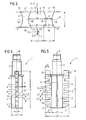
- FIG. 5 show a first embodiment of a treatment rotor 1 and parts thereof
- FIG. 6 A second embodiment of a treatment rotor.
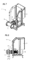
- FIGS. 7 and 8 show a device 7 for treating sludge S, in particular biogenic sludge, (or possibly also a mixture of sludge S and flocculant F), in particular for mixing in flocculant F or disintegrating sludge S.
- the treatment rotor 1 in a T-shaped Section of a transport or feed line 9 shown only in sections for the sludge S is rotatably mounted. The treatment rotor 1 protrudes into the interior of the feed line.
- the treatment rotor 1 has an inner hollow rotor base body 2 with an inner space 20, which is enclosed by a substantially hollow cylindrical wall 21, and a plurality of treatment elements 4 projecting or projecting on the rotor base body 2 and projecting outwards, in particular in the radial direction R radial direction and 14 on.
- the treatment rotor 1 is rotatable about an axis of rotation R extending centrally through the treatment rotor 1 and for this purpose has a coupling element (connection shaft) 3 adjoining the rotor base body 2 axially of the rotation axis R, via which the treatment rotor 1 is provided with an in FIG. 1 Not shown rotary drive (10 in FIG. 6 and 7
- the rotation direction of the rotational movement of the treatment rotor 1 is denoted by T and is generally a direction tangent to a circle about the rotation axis R or one along a circle about the rotation axis R running and the circle curvature following the following direction. In the example of FIG. 1 If the direction of rotation T is selected clockwise, but may also be directed in the opposite or counterclockwise direction or to avoid a clogging of the treatment rotor 1 are also changed regularly.
- the treatment elements 4 and 14 are in particular designed as treatment pins or treatment teeth.
- the treatment rotor 1 offset on opposite sides by approximately 180 ° two parallel to the axis of rotation R extending rectilinear rows of substantially equal to each other, each example five, treatment elements 4 on one side and 14 on the other side.
- the treatment rotor 1 is used as a mixing rotor and its treatment elements are designed as mixing elements and their treatment edges as mixing edges.
- Such an application is preferably described here.
- the treatment rotor 1 is a disintegration rotor and its treatment elements are designed as disintegration elements and their treatment edges as disintegration edges.
- apertures 6 are provided in the wall 21 in the circumferential direction or in the direction of rotation T.
- the openings as in FIG. 1, 2 and 5 to see as parallel to the axis of rotation R extending axial slots are formed, but also designed differently or arranged or can be varied in number.
- the openings 6 are also mutually offset by about 180 ° and the treatment elements 4 and 14 each about 90 °. Through the openings 6, the interior 20 of the rotor base body 2 with the outside space in flow communication.
- FIG. 6 are additional outlet openings 55 in the boundary walls 50 seen axially between the treatment elements 4 and 14, which open directly into the interstices 5 and 15 and also connect the interior 20 of the rotor body 2 with the outside space.
- the treatment elements 4 are spaced or separated by gaps 5 and the treatment elements 14 by gaps 15. However, it is also possible for more than two such rows of spaced-apart treatment elements to be provided.
- the treatment elements 4 and 14 all protrude outwardly substantially radially with respect to the axis of rotation R and each have four preferably rectilinear treatment edges 41, 42, 43 and 44 which are parallel to a radial direction perpendicular to the axis of rotation R, substantially perpendicular to the direction of rotation T and parallel to each other to the outside and have substantially the same length L4.
- the inlet opening 51 and the outlet opening 52 can, as shown, the same size or an equal (flow) cross-sectional area, preferably also have the same shape, but may also be different.
- the two treatment edges 41 and 43 are connected by a flat side 47 of the treatment element 4 and 14, while between the treatment edges 42 and 44 a further flat side 47 parallel flat side 48 of the treatment element 4 and 14 is located.
- the opposite treatment edges 41 and 42 and 43 and 44 on the two flat sides 47 and 48 are connected by concave, ie inwardly curved side walls 45 and 46, which thus also form the lateral boundary walls of the intermediate spaces 5 and 15, respectively from the perspective of the spaces 5 and 15 so convex, ie outwards, are curved.
- the shape of the side walls 45 and 46 is in each case in particular mirror-symmetrical with respect to a symmetry plane lying in the middle between the two flat sides 47 and 48 and parallel thereto, for example cylindrical.
- the two side walls 45 and 46 are preferably also mirror-symmetrical with respect to one another in the middle between the two treatment edges 41 and 43 and to the flat sides 47 and 48 orthogonal plane of symmetry.
- the axial width of the treatment elements 4 and 14, measured parallel to the axis of rotation R or perpendicular to the direction of rotation T first increases inwardly from a maximum width L2 at the front on the flat side 47 to a minimum at the center of the treatment element 4 or 14 Width from and then back to a maximum width L2 back of the flat side 48 too.
- the axial width of the intermediate spaces 5 and 15 measured parallel to the axis of rotation R or in the direction of rotation T increases from a minimum width L3 at the front to the center of the intermediate space 5 or 15 to a maximum width and then back to the rear a minimum width L3 outside.
- FIG 3 This is especially good in FIG 3 to recognize where, by way of example, a greater width B1 of the treatment element 4 with a corresponding smaller width W1 of the intermediate space 5 and a smaller width B2 of the treatment element 4 further inside with an associated larger width W2 of the intermediate space 5 are shown.
- This (more general) teaching for the design of the treatment elements or spaces is also by other embodiments except those in 1 to 5 illustrated, for example, by another design of their cross sections with different curved and / or asymmetric side walls 45 and 46 and other axial widths or widths.
- only one side wall 45 or 46 may be concave and the other flat or even convex.
- the outer surface of the treatment elements 4 and 14, which connects the end points of the treatment edges 41 to 44, is designated by 49 and is preferably designed as a flat side.
- the inner boundary walls of the intermediate spaces 5 and 15 are designated 50 and preferably also formed flat.
- treatment elements 7 and 17 are spaced from the adjacent first treatment element 4 and 14, however, which are curved at the end face to the rear Treatment rotor 1 better transverse to a pipe cross-section of a flow pipe for the mud S to fit. Due to the beveled or curved shaping beforehand, the treatment rotor 1 can be adapted to the curved inner walls of the tubular transport or feed line 9 and transversely to the longitudinal direction of the feed line 9, ie the transport direction of the sludge S, as far as possible into the feed line, without strike the treatment elements on rotation of the treatment rotor 1 on the inner walls, or touch them.
- the treatment elements or the treatment rotor 1 may vary according to the particular shape of the feed line.
- the treatment elements 4 and 14 may have substantially the same shape.
- At the rear ends of the two rows of treatment elements 4 and 14 is at a distance from the adjacent last treatment element 4 and 14 fastener 8 and 18 for attaching the treatment rotor 1 to a co-rotating part of a mechanical seal, not shown.
- the depth of the intermediate spaces 5 and 15 corresponds to the length L4 of the treatment edges 41 to 44.
- the space between the fastening element 8 or 18 and treatment element 4 or 14 is less deep with depth L8 for reasons of stability.
- the treatment elements 4 and 14 and 7 and 17 are preferably in pairs at the same axial positions along the axis of rotation R, as well as the fasteners 8 and 18. This is achieved in particular in an embodiment in which the treatment rotor 1 has a symmetry with respect to a rotation through 180 ° having. In one embodiment with three or four or generally n rows of treatment elements instead of only two, this rotational symmetry is then to be formed with respect to 120 ° or 90 ° or in general 360 ° / n.
- the total length of the two lateral rows of treatment elements 17 and 4 or 7 and 14 on the one hand and fastener 8 or 18 is denoted by L6.
- the outer diameter of the treatment rotor 1 between the outer sides of the two rows, corresponding to the outer surfaces 49 of the treatment elements 4 and 14, is denoted by L5.
- L7 is the diameter of the main body 2, so its (maximum) dimension is perpendicular to the axis of rotation R.
- L1 to L7 can be chosen without loss of generality: L1 between 6 mm and 28 mm, L2 between 3 mm and 17 mm, L3 between 2 mm and 14 mm, L4 between 12 mm and 220 mm, L5 between 80 mm and 510 mm, L6 between 88 mm and 530 mm and L7 between 21 mm and 270 mm.
- the mode of operation of the treatment rotor 1 can be described as follows:
- a flocculant F passed through or flowing through the interior space 20, as best shown in FIG. 2 can be seen, introduced through the apertures 6 substantially radially away from the axis of rotation R outwards into the sludge S located in the outer space.
- the mixture or mixture of sludge S and flocculant F is designated S + F.
- the flocculant F is used in a known manner and already described above for conditioning the sludge S, in particular for improving the efficiency in a subsequent mechanical liquid withdrawal, in particular dewatering, in particular by means of a press or centrifuge or a water-permeable textile bag or the like.
- the flocculant F introduced via the apertures 6 into the sludge S is then mixed further into the sludge S from the respective next and possibly following treatment element (s) 4 or 14 with treatment energy input and with a better degree of treatment.
- the sludge-flocculant mixture S + F is pressed or guided in a direction opposite to the direction of rotation T flow direction through the interstices 5 between the treatment elements 4 (or intermediate spaces 15 between the treatment elements 14), such as good at FIG. 3 to see.
- the mixture S + F enters through the inlet opening 51, which lies between the front in the direction of rotation T treatment edges 41 and 43 of the adjacent treatment elements 4, in the intermediate space 5 and thereby flows past these front treatment edges 41 and 43.
- the front treatment edges 41 and 43 operate or act as swirling and tear-off edges for the flow of the mud-flocculant mixture S + F.
- the mixture is now not pressed out or thrown outwards due to the centrifugal forces, but, in the case of the treatment rotor 1 according to the invention, forcedly initially remains on the treatment rotor 1.
- the mixture S + F of sludge S and flocculant F is pressed or guided through the gap 5, and flows out of the gap 5 only at the exit port 52.
- the mixture S + F also flows in forced flow past the second pair of opposing treatment edges 42 and 44 at the outlet opening 52 and is once again subjected to mixing energy and swirled by them.
- the number of effective or on the same volume of the mud-flocculant mixture S + F acting treatment edges is increased by four according to a first effect of the invention by four, namely the four adjacent to the gap 5 (or 15) treatment edges 41 to 44 of the adjacent treatment elements 4 (or 14).
- an effective edge length of the treatment edges is obtained or swirl edges of 4 L4 per gap 5 or 15 and 4 L8 in the last two spaces.
- the total edge length would be 40 L4 + 8 L8.
- This increased treatment edge number or length according to the invention results in a significant improvement of the treatment result or the mixing energy input.
- a second effect results from the change of the flow cross-section in the gap 5 (or 15) for the mixture S + F flowing through.
- the mixture S + F is decompressed first due to the initially increasing cross-section of the gap 5 (or 15) in the direction of flow, ie the static pressure is reduced due to the higher dynamic pressure, and subsequently due to the subsequently decreasing cross-section of the gap 5 (or 15). compressed. If the inlet opening 51 and the outlet opening 52 have substantially the same flow cross-section, so are the static pressures at the entrance and exit of the mixture S + F in and out of the gap 5 (or 15) is substantially equal.
- the mixture S + F is sucked into the interspaces 5 (15) by the pressure curve within the interspaces 5 (15) and does not deviate outwards before the rear treatment edges 42 and 44, but instead also flows over the rear treatment edges 42 and 44 at Exit from the spaces 5 (15) almost completely.
- the same volume element of the sludge-flocculant mixture S + F is thus guided past both the front treatment edges 41 and 43 and the rear treatment edges 42 and 44 and further vortexed and mixed.
- the said second effect is itself caused by the pressure differences, which may cause cavitation effects even beyond a certain size, such as in a cavitation nozzle, which improve the mixing of the mixture S + F also during the flow within the gap 5 (15) between the treatment edges ,
- the axial width of the treatment elements 4 and 14 increases in the direction of rotation T, the axial width of the treatment elements 4 and 14 from a minimum width B2 front of the flat side 47 to a maximum width B1 rear of the flat side 48 and accordingly in the direction of rotation T.
- the axial width of the intermediate spaces 5 and 15 decreases from a maximum width W2 in the front to a minimum width W1 at the rear.
- the inlet opening 51 of the intermediate spaces 5 and 15 in this embodiment is therefore always larger than the outlet opening 52 of the intermediate spaces 5 and 15.
- the sludge-flocculant mixture S + F is only compressed on its way through the intermediate spaces between the treatment elements and not decompressed first. Also in this embodiment good mixing results are achieved.
- treatment edges can also be provided only at the outlet opening 52, while at the inlet opening also blunt or curved and / or funnel-shaped inlet regions can be provided.
- the ratio B1 / B2 of the maximum axial width B1 to the minimum width B2 of the treatment elements 4 and 14 is preferably greater than 2, preferably between 2 and 3.5.
- the ratio W2 / W1 of the maximum axial width W2 to the minimum width W1 of the interstices 5 and 15 is preferably greater than 1.4, preferably between 1.5 and 2.8, selected.
- These ratios B1 / B2 or W2 / W1 are a measure of the relative decrease or increase in the axial width of the treatment elements or the axial width of the spaces between the treatment elements and thus also determine the degree of compression (or decompression, if necessary) of the sludge flocculant Mixture S + F.
- the gaps 5 and 15 may also be completed radially outward to prevent squeezing out of the sludge-flocculant mixture S + F due to the centrifugal forces.
- the longitudinal part may again treatment edges, in particular axially extending treatment edges on the outside, and in particular be designed as a square or square tube, which is applied from the outside to the outer surfaces of the treatment elements, for example by welding.
- a reversing function or a reversing operation for cleaning the gaps 5 and 15 may be provided, in which the rotor is rotated in the opposite direction to the provided in mixing operation direction of rotation T, especially to remove larger particles from the spaces.
- the treatment edges 41 to 44 are preferably formed sharp-edged, in order to achieve a good turbulence.
- the surface of the treatment rotor 1 can be provided at least at the treatment edges with a wear protection layer, e.g. a layer produced by plasma nitriding or a ceramic coating, in particular an aluminum oxide layer, for example by spraying, or else a hard material layer, e.g. be provided a TiN or TiCN layer.
- the treatment elements 4 and 14 may be integrally connected to each other and / or with the base body or inserted as prefabricated parts in openings in the body and inserted into the interior and then fastened by means of screws and / or transverse pins.
- FIGS. 7 and 8 is to rotate the treatment rotor 1 in the feed line 9 of this, z. B. non-positively coupled via the coupling element 3 with a motor 10.
- sludge S is pumped or guided through the feed line 9 while the treatment rotor 1 is rotated by the motor 10.
- flocculant is supplied by the treatment rotor 1.
- the treatment rotor 1 is preferably completely surrounded by sludge S, which is particularly advantageous with regard to the treatment efficiency.
- the cross-sectional area claimed by the treatment rotor 1, which corresponds in particular to the product L5 ⁇ L6 in the illustrated embodiment, is greater than 50% and less than 74% of the flow cross-sectional area of the feed line section of the feed line 9, in which the treatment rotor 1 is arranged ,
- sealing elements can be provided to seal the coupling element 3 against the feed line 9 against the passage of sludge S or liquid.
- a Control unit for the motor 10 and the non-illustrated (s) for the flocculant F and preferably also the sludge S is denoted by 11.
- the speed of the treatment rotor 1 can advantageously between 1200 and 4000 rev / min. can be selected, the sludge volume flow in the feed line 9 may typically be from 3 to 400 m 3 per hour.
- the apparatus 7 may be downstream of a drying device, not shown, in particular, a filter press or a centrifuge for drying or dewatering of the sludge S in the flow direction or transport direction of the sludge S, wherein the flocculant F remains largely in the separated water or liquid.
- FIGS. 7 and 8 Device shown can also further, the treatment rotor 1 shown upstream or downstream or also connected in parallel specialistssgrunsgrotoren 1, which can be integrated analogously to the manner described above in the feed line 9.
- the operation and design of the treatment rotor 1 can remain substantially the same.
- the disintegration effect is greatly improved by the design of the treatment rotor according to the invention, in particular the described Verwirbelungs- and compression and decompression, analogous to the interference effect.
- the breakthroughs 6 can serve here for the passage of sludge S or omitted altogether.
Description
Die Erfindung betrifft eine Vorrichtung und ein Verfahren jeweils zum Behandeln von Schlämmen, insbesondere industrieller oder biogener Herkunft.The invention relates to a device and a method in each case for treating sludges, in particular of industrial or biogenic origin.
Solche Vorrichtungen und Verfahren finden zur Behandlung oder auch Sanierung von Schlämmen Verwendung, insbesondere von Schlämmen industrieller Herkunft, von Schlämmen aus dem Bergbau, von Sedimentschlämmen in Gewässern und/oder auch von biogenen Schlämmen.Such apparatus and methods find use in the treatment or remediation of sludges, particularly sludges of industrial origin, sludges from mining, sediment sludges in waters and / or even biogenic sludges.
Bei biogenen Schlämmen tierischen oder menschlichen Ursprungs handelt es sich üblicherweise um Gemische aus flüssiger Phase oder Flüssigkeit, meist hauptsächlich Wasser, und fester Phase oder Feststoffteilchen. Die feste Phase umfasst dabei in der Regel biogene Partikel oder organische Feststoffe, Zellen und Mikroorganismen, insbesondere Bakterien, und Aggregate daraus. Zusätzlich können biogene Schlämme organische oder anorganische Stoffe umfassen sowie eine Gasphase, z. B. in Form von Gasblasen oder gelöstem Gas. Das Gas kann aus aerobem oder anaerobem Abbau von organischem Material stammen. Biogene Schlämme der Abwasserreinigung werden auch als Klärschlämme bezeichnet.Biogenic sludges of animal or human origin are usually mixtures of liquid phase or liquid, usually mainly water, and solid phase or solid particles. As a rule, the solid phase comprises biogenic particles or organic solids, cells and microorganisms, in particular bacteria, and aggregates thereof. In addition, biogenic sludges may include organic or inorganic matter as well as a gaseous phase, e.g. B. in the form of gas bubbles or dissolved gas. The gas may be from aerobic or anaerobic degradation of organic matter. Biogenic wastewater treatment sludges are also referred to as sewage sludge.
Bei Kläranlangen kommt das zu reinigende Abwasser bzw. Schmutzwasser üblicherweise nach einer mechanischen Vorreinigung in ein Vorklärbecken, in dem sich ungelöste Stoffe wie Fäkalstoffe und Papier etc. absetzen oder an der Oberfläche aufschwimmen. Vorgeklärtes Schmutzwasser wird dann üblicherweise einer biologischen Klärstufe unterzogen. Dabei werden organische Stoffe, insbesondere aerob durch Mikroorganismen, abgebaut und anorganische Stoffe teilweise oxidiert. Übliche Verfahren für diese biologische Stufe sind Belebtschlammverfahren mit nachgeschalteter Nachklärung. Beim Belebtschlammverfahren werden biogene Inhaltsstoffe des Ab- bzw. Schmutzwassers durch Zugabe von Belebtschlamm, welcher z. B. geflockt aggregierte Bakterien enthält, unter Luftzufuhr biotisch oxidativ aerob kontinuierlich abgebaut. Bei der Nachklärung sedimentiert der Belebtschlamm und wird so aus dem Abwasser abgetrennt. Ein Teil des Schlamms kann als sog. Rücklaufschlamm ins Belebtschlammverfahren rückgeführt werden, um die Konzentration der Mikroorganismen ausreichend hoch zu halten. Der überschüssige Schlamm, der durch Biomassewachstum bei der Nachklärung entstanden ist, wird zur Weiterbehandlung zusammen mit dem Primärschlamm der Vorklärung eingedickt und dann z. B. in Faultürmen anaerob weiter abgebaut. Daraus resultierender Faulschlamm wird nach Durchlaufen eines Nacheindickers einer Schlammpresse zur Entwässerung zugeführt und kann nach Entwässern entsorgt werden. Klärverfahren können auch ohne Vorklärung durchgeführt werden. Dabei wird nur der Überschussschlamm aus der Nachklärung über einen Voreindicker, in der Regel ohne Faulturm, der Schlammpresse zugeführt.In sewage treatment sewage or dirty water usually comes after a mechanical pre-treatment in a primary clarifier, in which settle undissolved substances such as faeces and paper, etc. or float on the surface. Pre-clarified wastewater is then usually subjected to a biological treatment stage. In this case, organic substances, in particular aerobically degraded by microorganisms, and partially oxidized inorganic substances. Typical processes for this biological stage are activated sludge processes with subsequent clarification. The activated sludge process uses biogenic ingredients the waste or dirty water by adding activated sludge, which z. B. contains flocculated aggregated bacteria, aerobically degraded aerobically under air supply biotics oxidative. In the secondary clarification, the activated sludge sediments and is separated from the wastewater. Part of the sludge can be returned to the activated sludge process as so-called return sludge, in order to keep the concentration of the microorganisms sufficiently high. The excess sludge caused by biomass growth in the final clarification is thickened for further treatment together with the primary sludge of the primary treatment and then z. B. in digestion towers anaerobically further degraded. Resulting digested sludge is fed after passing through a Nacheindickers a sludge press for drainage and can be disposed of after dewatering. Clarification processes can also be carried out without primary treatment. In this case, only the excess sludge from the secondary clarification via a pre-thickener, usually without digester, fed to the sludge press.
Zum Entwässern von Schlämmen, insbesondere Klär- oder Industrieschlämmen oder Sedimentschlämmen, ist es bekannt, den im Wesentlichen aus Wasser bestehenden Flüssigkeitsanteil des Schlamms mit einer Filteranlage oder einer Zentrifuge abzuscheiden, wobei gleichzeitig feste Bestandteile aus dem Schlamm abgeschieden werden. Ferner sind auch Entwässerungen mit Säcken oder Schläuchen aus (geo)textilen Filtermaterialen bekannt.For dewatering sludges, in particular sewage or industrial sludges or sediment sludges, it is known to separate the substantially water-containing liquid fraction of the sludge with a filter system or a centrifuge, at the same time solid components are separated from the sludge. Furthermore, drainage with bags or hoses made of (geo) textile filter materials are known.
Dem Schlamm wird nun üblicherweise vor der Entwässerung ein Flockmittel (Flockungshilfsmittel), das Polymere enthält, versetzt, um den Entwässerungsgrad oder den Trocknungsgrad des Schlammes zu erhöhen, also den Schlamm besser zu entwässern. Die Wirkungsweise des Flockmittels kann man sich so vorstellen, dass die Polymere die Feststoffteilchen im Schlamm in Flocken oder unter Flockenbildung aneinander binden und dadurch deren Trennung vom Wasser unterstützen oder verbessern. Die herausgefilterte entwässerte Trockenmasse wird auch als Filterkuchen bezeichnet. Die Polymere verbessern auch den Durchgang des Wassers durch den Filterkuchen bei den nachfolgenden Schlammmengen.The sludge is now usually before dewatering a flocculant (flocculant) containing polymers, added to increase the degree of dewatering or the degree of drying of the sludge, so to better drain the sludge. The mode of action of the flocculant can be thought of as the polymers binding the particulate matter in the sludge in flakes or flocculation and thereby assisting or improving their separation from the water. The filtered dehydrated dry matter is also used as a filter cake designated. The polymers also improve the passage of water through the filter cake at the subsequent sludge levels.
Aus der
Die Wirksamkeit der biologischen Reinigungsstufe in Kläranlagen kann dadurch erhöht werden, dass man Homogenisatoren oder auch Desintegratoren zum Behandeln des Klärschlamms, insbesondere des Rücklaufschlamms, Primärschlamms oder Überschussschlamms und auch des Faulschlamms, einsetzt.The effectiveness of the biological treatment stage in sewage treatment plants can be increased by using homogenizers or disintegrators for treating the sewage sludge, in particular the return sludge, primary sludge or excess sludge and also the digested sludge.
nen Feststoffpartikel verkleinert und homogenisiert werden, wodurch eine größere effektive Oberfläche für den Abbau zur Verfügung gestellt wird. Ferner können durch Desintegration an Zellwänden anhaftende Enzyme und biogene Partikel abgelöst und somit in die flüssige Phase eingebracht werden. Weiter können bei der Desintegration Zellwände von Zellen und dgl. zumindest teilweises aufgeschlossen werden, wodurch Endoenzyme der Zellen freigesetzt werden. Insbesondere die genannten Wirkungen der Desintegration erhöhen den Wirkungsgrad des biologischen Abbaus durch Mikroorganismen im Schlamm, insbesondere im Belebtschlamm der biologischen Abbaustufe.reduced solid particles and homogenized, whereby a larger effective surface for the degradation is provided. Furthermore, by disintegration on cell walls adhering enzymes and biogenic particles can be detached and thus introduced into the liquid phase. Further, in the disintegration, cell walls of cells and the like can be at least partially disrupted, thereby releasing endoenzymes of the cells. In particular, the above-mentioned effects of disintegration increase the efficiency of biodegradation by microorganisms in the sludge, especially in the activated sludge of the biological degradation stage.
Ein Desintegrationsrotor für Klärschlämme ist beispielsweise aus der
Aus der
Die
Aus der
Die
Aus
Zwar kann mit den bekannten Desintegrationsrotoren eine Desintegration von Schlämmen erreicht werden. Die erreichbare Desintegrationswirkung ist jedoch noch verbesserungswürdig.Although a disintegration of sludge can be achieved with the known disintegration rotors. However, the achievable disintegration effect is still in need of improvement.
Ausgehend davon ist es insbesondere eine Aufgabe der Erfindung, eine neue Vorrichtung sowie ein neues Verfahren jeweils zum Behandeln, insbesondere Einmischen von Konditioniermittel und/oder Desintegrieren, von Schlämmen bereitzustellen.On the basis of this, it is a particular object of the invention to provide a new device and a new method in each case for treating, in particular mixing of conditioning agent and / or disintegrating, of sludges.
Diese Aufgabe wird gelöst durch die Merkmale des Patentanspruchs 1. Ausgestaltungen und Weiterbildungen gemäß der Erfindung ergeben sich aus den abhängigen Ansprüchen.This object is achieved by the features of
Die Vorrichtung gemäß Patentanspruch 1 ist zum Behandeln von Schlämmen, insbesondere biogenen oder industriellen Ursprungs, geeignet und bestimmt und umfasst zumindest einen im Schlamm angeordneten oder anordenbaren Behandlungsrotor, der um eine, im Allgemeinen durch, vorzugsweise zentral durch, den Behandlungsrotor verlaufende, Rotationsachse rotiert oder rotierbar ist und von der Rotationsachse gesehen nach außen vorspringende Behandlungselementen, zwischen denen Zwischenräume gebildet sind, wobei wenigstens ein Teil der Behandlungselemente an wenigstens einem, vorzugsweise jedem, angrenzenden Zwischenraum jeweils wenigstens eine Behandlungskante, vorzugsweise wenigstens zwei voneinander beabstandete Behandlungskanten, aufweisen, wobei jede dieser Behandlungskanten von der Rotationsachse gesehen von innen nach außen verläuft. Der Verlauf der Behandlungskanten ist insbesondere so, dass der Abstand der Punkte auf der Behandlungskante von der Rotationsachse entlang des Verlaufs oder der Erstreckung der Behandlungskante stetig, vorzugsweise streng monoton, zunimmt. Insbesondere ist der Verlauf der Behandlungskanten radial oder linear, kann aber auch gekrümmt oder auch linear und schräg zur radialen Richtung sein. Gemäß Patentanspruch 1 nimmt die in Richtung parallel zur Rotationsachse gemessene Breite wenigstens eines Teils der Behandlungselemente in Rotationsrichtung (oder: Umlaufrichtung, Umfangsrichtung) zunächst ab und dann erst wieder zu, vorzugsweise derart, dass die die Behandlungselemente eine konkav gekrümmte, vorzugsweise bikonkav gekrümmte, Gestalt haben. Zusätzlich nimmt die in Richtung parallel zur Rotationsachse gemessene Innenabmessung wenigstens eines Teils der Zwischenräume zwischen den Behandlungselementen in Rotationsrichtung zunächst zu und dann wieder ab, vorzugsweise derart, dass die Zwischenräume jeweils konvex gekrümmt, vorzugsweise bikonvex gekrümmt, ausgebildet sind. Die Variation der Breite oder Innenabmessung in Rotations- oder Umlaufrichtung ist bevorzugt kontinuierlich, schließt es aber beispielsweise nicht aus, dass die Breite oder Innenabmessung abschnittsweise konstant ist.The device according to
Durch diese Veränderung der Breite der Behandlungselemente bzw. der Innenabmessung der Zwischenräume kommt es an den Behandlungselementen oder in den Zwischenräumen zwischen benachbarten Behandlungselementen zu einer zusätzlichen Dekompression und anschließenden Kompression des Schlamm-Konditioniermittel-Gemisches oder des Schlammes. Einerseits wird aufgrund dieser Druck- und Strömungsverhältnisse die Strömungsführung des Schlamm-Konditioniermittel-Gemischs oder des Schlammes in den Zwischenräumen verbessert und dieses auch an einer zweiten in Rotationsrichtung hinter einer vorderen Behandlungskante gelegenen Behandlungskante am Zwischenraum verwirbelt und somit an wenigstens zwei Behandlungskanten nacheinander mit Mischenergie beaufschlagt. Aufgrund dieser erzwungenen Strömung durch den Zwischenraum infolge dessen Geometrie entsteht also ein zusätzlicher Behandlungseffekt mit weiter gesteigertem Mischenergieeintrag. Andererseits führt die Dekompression und anschließende Kompression des Schlamm-Konditioniermittel-Gemischs zu zusätzlichen Behandlungseffekten infolge der Druckunterschiede bis hin zu Kavitationseffekten. Die Eintrittsöffnung der Zwischenräume kann in dieser Ausführungsform in Gestalt und Größe gleich zur Austrittsöffnung gewählt sein, jedoch auch unterschiedlich sein.As a result of this change in the width of the treatment elements or the inner dimensions of the interstices, additional decompression and subsequent compression of the sludge-conditioning agent mixture or of the sludge occurs at the treatment elements or in the intermediate spaces between adjacent treatment elements. On the one hand, owing to these pressure and flow conditions, the flow guidance of the sludge-conditioning agent mixture or of the sludge in the intermediate spaces is improved and this is also swirled at a second treatment edge located behind a front treatment edge in the direction of rotation at the intermediate space and thus subjected to mixing energy at least two treatment edges in succession , Due to this forced flow through the gap due to its geometry thus creates an additional treatment effect with further increased mixing energy input. on the other hand The decompression and subsequent compression of the sludge-conditioning agent mixture leads to additional treatment effects due to the pressure differences to cavitation effects. The inlet opening of the intermediate spaces can be selected in this embodiment in shape and size equal to the outlet opening, but also be different.
Das Behandeln des Schlammes ist in einer vorteilhaften Ausführungsform ein Einmischen von Konditioniermittel, insbesondere Flockmittel, in den Schlamm, wobei der Behandlungsrotor dann als Einmischrotor ausgebildet ist und die Behandlungselemente des Behandlungsrotors als Einmischelemente ausgebildet sind und jede Behandlungskante als Einmischkante ausgebildet ist.The treatment of the sludge is in an advantageous embodiment, a mixing of conditioning, in particular flocculant, in the mud, wherein the treatment rotor is then formed as a mixing rotor and the treatment elements of the treatment rotor are formed as Einmischelemente and each treatment edge is formed as a mixing edge.
In einer weiteren vorteilhaften Ausführungsform ist das Behandeln des Schlammes eine Desintegration des Schlammes, wobei der Behandlungsrotor als Desintegrationsrotor ausgebildet ist und die Behandlungselemente des Behandlungsrotors als Desintegrationselemente ausgebildet sind und jede Behandlungskante als Desintegrationskante ausgebildet ist.In a further advantageous embodiment, the treatment of the sludge is a disintegration of the sludge, wherein the treatment rotor is designed as a disintegration rotor and the treatment elements of the treatment rotor are designed as disintegration elements and each treatment edge is designed as a disintegration edge.
Die Ausführungsformen zum Einmischen von Konditioniermittel und zum Desintegrieren können auch miteinander kombiniert werden, insbesondere in zweistufigen Systemen oder Prozessen nacheinander.The embodiments for mixing in conditioning agents and for disintegrating can also be combined with one another, in particular in two-stage systems or processes one after the other.
Die Erfindung beruht auf der Überlegung, an einem Behandlungsrotor mehrere nach außen von der Rotationsachse des Behandlungsrotors weg oder quer zur Rotationsachse vorragende (oder: vorspringende) Behandlungselemente (oder: Behandlungszähne, Behandlungszapfen) vorzusehen, die durch Zwischenräume (oder: Spalte) voneinander getrennt oder beabstandet sind und die ferner zu dem anschließenden oder angrenzenden Zwischenraum oder den anschließenden oder angrenzenden Zwischenräumen hin jeweils wenigstens zwei nach außen in Richtung von der Rotationsachse weg verlaufende und voneinander beabstandete Behandlungskanten aufweisen.The invention is based on the consideration of providing a treatment rotor with a plurality of treatment elements (or: projecting teeth) projecting outwardly away from the axis of rotation of the treatment rotor or transverse to the axis of rotation, separated by spaces (or: gaps) are spaced apart and further to the adjacent or adjacent space or the adjacent or adjacent spaces towards each at least two outwardly in the direction of the Have rotational axis away and spaced apart treatment edges.
Dieses Maßnahmenbündel gemäß der Erfindung verbessert in synergistischer Weise die Behandlungswirkung, insbesondere Einmischwirkung oder Desintegrationswirkung, des Behandlungsrotors und vergrößert die einbringbare Behandlungsenergie, insbesondere Mischenergie oder Zersetzungsenergie zum Desintegrieren von Bestandteilen des Schlammes, insbesondere Zellaggregaten oder Zellen.This set of measures according to the invention synergistically improves the treatment effect, in particular mixing effect or disintegration effect, of the treatment rotor and increases the input treatment energy, in particular mixing energy or decomposition energy for disintegrating components of the sludge, in particular cell aggregates or cells.
Insbesondere wird durch die Mäandrierung oder Einführung beabstandeter Behandlungselemente die effektive Kantenlänge der (wirksamen) Behandlungskanten vergrößert, die als Verwirbelungskanten die Vermischung des Flockmittels im Schlamm oder die Desintegration des Schlammes erheblich vergrößern. Die Zwischenräume zwischen den Behandlungselementen führen das Schlamm-Konditioniermittel-Gemisch oder den Schlamm bei der Rotation des Rotors an den Behandlungskanten vorbei, so dass auch die Behandlungskanten praktisch über ihre volle Länge auf das Gemisch oder den Schlamm einwirken und Behandlungsenergie eintragen können. Außerdem kann die Drehzahl des Rotors aufgrund dessen höheren Wirkungsgrades reduziert und damit, im Allgemeinen elektrische, Antriebsenergie eingespart werden.In particular, by meandering or introducing spaced-apart treatment elements, the effective edge length of the (effective) treatment edges is increased, which considerably increase the mixing of the flocculant in the sludge or the disintegration of the sludge as swirling edges. The interstices between the treatment elements pass the mud-conditioning agent mixture or slurry past the treatment edges as the rotor rotates, so that the treatment edges can also act on the mixture or sludge and apply treatment energy over virtually their full length. In addition, the speed of the rotor can be reduced due to its higher efficiency and thus, generally electrical, drive energy can be saved.
Bei einem Flockmittel als Konditioniermittel steht die eingebrachte Mischenergie in direkter Korrelation zur Bindungsenergie bei der Flockulation/Ausbildung der Flocken, so dass also auch die Flockulierung infolge der Maßnahmen gemäß der Erfindung verbessert werden kann.In the case of a flocculant as a conditioning agent, the introduced mixing energy is directly correlated to the binding energy in the flocculation / formation of the flocs, so that therefore also the flocculation as a result of the measures according to the invention can be improved.
Damit wird gemäß der Erfindung eine vollständig neue Generation von Mischvorrichtungen zum Einmischen von Konditioniermitteln, insbesondere Flockmitteln, in Schlämme geschaffen, die aufgrund der enormen Steigerungen im Wirkungsgrad und der damit erzielten Energieeinsparung die bisherigen Mischvorrichtungen technologisch ablösen wird. Die Erfindung stellt somit einen technologischen und wirtschaftlichen Quantensprung im Bereich der Flockulations- und Einmischtechnik dar. Vergleichbares lässt sich über die Anwendung zur Desintegration von Schlämmen sagen. Bei den Schlämmen kann es sich um beliebige Schlämme, insbesondere Klärschlämme oder Industrieschlämme, handeln.Thus, according to the invention, a completely new generation of mixing devices for mixing of conditioning agents, especially flocculants, created in sludge, which will replace the previous mixing devices technologically due to the enormous increases in efficiency and thus achieved energy savings. The invention represents a technological and economic quantum leap in the field of flocculation and mixing technology. Comparable can be said about the application for the disintegration of sludge. The sludges may be any sludge, in particular sewage sludge or industrial sludge.
In vorteilhaften Varianten gemäß der Erfindung weisen die Behandlungselemente oder alternativ oder zusätzlich die Zwischenräume zwischen den Behandlungselementen eine besondere Form hinsichtlich ihrer Querschnitte auf.In advantageous variants according to the invention, the treatment elements or alternatively or additionally the intermediate spaces between the treatment elements have a special shape with regard to their cross-sections.
Das Verhältnis einer maximalen Breite zu einer minimalen Breite der Behandlungselemente ist bevorzugt größer 2, vorzugsweise zwischen 2 und 3,5, gewählt. Das Verhältnis einer maximalen Weite zu einer minimalen Weite der Zwischenräume ist bevorzugt größer 1,4, vorzugsweise zwischen 1,5 und 2,8, gewählt.The ratio of a maximum width to a minimum width of the treatment elements is preferably greater than 2, preferably between 2 and 3.5. The ratio of a maximum width to a minimum width of the intermediate spaces is preferably greater than 1.4, preferably between 1.5 and 2.8.
Bevorzugt wird das Konditioniermittel zwischen zwei in Rotationsrichtung aufeinander folgenden Behandlungselementen in den Schlamm eingebracht, insbesondere indem das Konditioniermittel durch zwischen den Behandlungselementen liegende Durchbrüche oder Öffnungen in dem Rotor von einem Rotorinnenraum nach außen zugeführt wird. Das Konditioniermittel kann aber auch alternativ oder zusätzlich in die Zwischenräume direkt durch zwischen den an den jeweiligen Zwischenraum vorgesehenen Behandlungselementen angeordnete Auslassöffnungen im Rotor eingebracht werden, die in die Zwischenräume direkt münden.The conditioning agent is preferably introduced into the sludge between two treatment elements following one another in the direction of rotation, in particular by the conditioner being supplied to the outside from a rotor interior through openings or openings in the rotor located between the treatment elements. However, the conditioning means can alternatively or additionally be introduced into the interspaces directly through outlet openings in the rotor which are arranged between the treatment elements provided at the respective intermediate space and which open directly into the intermediate spaces.
Besonders effektiv erweist sich der Behandlungsrotor, wenn dieser bei dessen Rotation um die Rotationsachse vollständig in den Schlamm eintaucht bzw. von diesem umgeben ist.
Die Behandlungskanten sind bevorzugt an oder in Randbereichen der Zwischenräume angeordnet, welche Eintrittsöffnungen oder Austrittsöffnungen der Zwischenräume für das Gemisch aus Schlamm und Konditioniermittel bilden. Da an diesen Randbereichen zusätzlich die Strömungsquerschnitte der Zwischenräume am kleinsten sind, ist die Strömungsgeschwindigkeit dort am größten und damit auch die Verwirbelung an den Behandlungskanten optimiert.The treatment rotor proves to be particularly effective if, during its rotation about the axis of rotation, it is completely immersed in the sludge or surrounded by it.
The treatment edges are preferably arranged on or in edge regions of the intermediate spaces, which inlet openings or outlet openings of the intermediate spaces for the mixture of sludge and conditioning agent form. Since the flow cross sections of the interspaces are also smallest at these edge regions, the flow velocity is greatest there and thus also the turbulence at the treatment edges is optimized.
In einer besonders vorteilhaften Ausführungsform liegen zwei Behandlungskanten von zwei verschiedenen an denselben Zwischenraum angrenzenden Behandlungselementen einander gegenüber, wodurch das Gemisch zwischen den beiden praktisch gleichzeitig oder gemeinsam einwirkenden Einmischkanten besonders stark verwirbelt und mit Mischenergie beaufschlagt wird.In a particularly advantageous embodiment, two treatment edges of two different adjacent to the same space treatment elements face each other, whereby the mixture between the two practically simultaneously or jointly acting interference edges is particularly strongly fluidized and charged with mixing energy.
Bevorzugt sind zwei vordere Behandlungskanten an der Eintrittsöffnung des Zwischenraumes einander gegenüber liegend und zwei hintere Behandlungskanten an der Austrittsöffnung des Zwischenraumes einander gegenüber liegend angeordnet. Dadurch können jeweils zwei Behandlungskanten an den engsten Stellen unmittelbar von beiden Seiten oder gemeinsam auf das Gemisch einwirken und zwar zunächst bei dessen Eintritt in den Zwischenraum und dann bei dessen Austritt aus dem Zwischenraum.Preferably, two front treatment edges at the inlet opening of the intermediate space are arranged opposite one another and two rear treatment edges are arranged opposite one another at the outlet opening of the intermediate space. As a result, two treatment edges at the narrowest points in each case can act on the mixture directly from both sides or together, and specifically at its entry into the space and then on its exit from the space.
Diese Maßnahmen führen zu einem weiter verbesserten Behandlungswirkungsgrad.These measures lead to a further improved treatment efficiency.
In einer besonderen konstruktiven Ausgestaltung sind wenigstens zwei Behandlungskanten eines Behandlungselementes durch eine Flachseite verbunden, insbesondere zwei Behandlungskanten durch eine erste Flachseite und zwei weitere Behandlungskanten durch eine weitere, vorzugsweise zur ersten Flachseite parallele zweite Flachseite. Ferner sind bevorzugt gegenüberliegende Behandlungskanten an den beiden Flachseiten über konkav gekrümmte Seitenwände miteinander verbunden, die seitliche Begrenzungswände der Zwischenräume bilden. Die Seitenwände sind vorzugsweise spiegelsymmetrisch bezüglich wenigstens einer Symmetrieebene ausgebildet, vorzugsweise bezüglich einer in der Mitte zwischen den beiden Flachseiten liegenden und zu diesen parallelen Symmetrieebene und/oder bezüglich einer in der Mitte zwischen zwei Behandlungskanten und zu den Flachseiten orthogonalen Symmetrieebene.In a particular structural embodiment, at least two treatment edges of a treatment element are connected by a flat side, in particular two treatment edges by a first flat side and two further treatment edges by a second, preferably flat to the first flat side flat side. Furthermore, preferably opposite treatment edges on the two flat sides are connected to one another via concavely curved side walls, which form lateral boundary walls of the intermediate spaces. The side walls are preferably mirror-symmetrical with respect to at least one plane of symmetry, preferably with respect to a symmetry plane lying in the middle between the two flat sides and parallel to them and / or with respect to a plane of symmetry orthogonal in the middle between two treatment edges and to the flat sides.
Ferner kann eine die Endpunkte der Behandlungskanten verbindende (radial außen liegende) Außenfläche des Behandlungselements als Flachseite ausgebildet sein und/oder eine innere (radial innen liegende) Begrenzungswand des Zwischenraumes als Flachseite ausgebildet sein. Die Länge der Behandlungselemente oder der Behandlungskanten ist im Allgemeinen größer als die lichte Weite der Zwischenräume, insbesondere vorzugsweise wenigstens um das 1,5-fache bis 3-fache.Furthermore, a (radially outer) outer surface of the treatment element connecting the end points of the treatment edges may be formed as a flat side and / or an inner (radially inner) boundary wall of the intermediate space may be formed as a flat side. The length of the treatment elements or the treatment edges is generally greater than the clear width of the intermediate spaces, in particular preferably at least 1.5 times to 3 times.
Im Allgemeinen weist der Behandlungsrotor einen Rotorgrundkörper auf, an dem die Behandlungselemente befestigt oder angeformt sind. Der Rotorgrundkörper ist bevorzugt innen hohl mit einem Innenraum, der von einer, vorzugsweise im Wesentlichen hohlzylindrischen, Wandung umschlossen ist.In general, the treatment rotor has a rotor base body on which the treatment elements are attached or molded. The rotor base body is preferably hollow inside with an interior, which is enclosed by a, preferably substantially hollow cylindrical, wall.
Vorzugsweise ist wenigstens ein Durchbruch in der Wandung vorgesehen, über den der Innenraum des Rotorgrundkörpers mit dem Außenraum in Strömungsverbindung steht, so dass in dem oder durch den Innenraum strömendes Konditioniermittel durch den wenigstens einen Durchbruch in den im Außenraum befindlichen Schlamm einbringbar ist oder eingebracht werden kann. Wenigstens ein Durchbruch kann als im Wesentlichen parallel zur Rotationsachse verlaufender axialer Schlitz ausgebildet sein.Preferably, at least one opening in the wall is provided, via which the interior of the rotor base body is in flow communication with the exterior space, so that conditioning medium flowing through or through the interior can be introduced or introduced through the at least one opening in the sludge located in the exterior space , At least one breakthrough may be formed as extending substantially parallel to the axis of rotation axial slot.
Es ist besonders vorteilhaft, wenn der oder die Durchbrüche in Rotationsrichtung gesehen zwischen Behandlungselementen angeordnet und/oder zwischen jeweils zwei Behandlungselementen ist in Rotationsrichtung gesehen jeweils wenigstens ein Durchbruch angeordnet. Die Durchbrüche sind vorzugsweise zueinander in Rotationsrichtung versetzt, vorzugsweise äquidistant verteilt, angeordnet, insbesondere paarweise zueinander um etwa 180° versetzt und/oder zu den, vorzugsweise um 180° versetzten Behandlungselementen jeweils um etwa 90° versetzt.It is particularly advantageous if, viewed in the direction of rotation, the aperture or apertures are arranged between treatment elements and / or between at least two treatment elements, at least one aperture is arranged in the direction of rotation. The apertures are preferably mutually offset in the direction of rotation, preferably distributed equidistantly, arranged, in particular offset in pairs to each other by about 180 ° and / or offset to the, preferably offset by 180 ° treatment elements in each case by about 90 °.
Der Behandlungsrotor weist im Allgemeinen ein sich an den Rotorgrundkörper axial zur Rotationsachse anschließendes Kopplungselement auf, über welches der Behandlungsrotor mit einem, vorzugsweise drehzahlgeregelten oder drehzahlregelbaren, Rotationsantrieb, insbesondere einer Drehwelle des Rotationsantriebs, gekoppelt werden kann zum Rotieren des Behandlungsrotors um die Rotationsachse.The treatment rotor generally has a coupling element which adjoins the rotor base body axially to the axis of rotation and via which the treatment rotor can be coupled to a preferably speed-controlled or speed-controllable rotary drive, in particular a rotary shaft of the rotary drive, for rotating the treatment rotor about the axis of rotation.
Gemäß einer vorteilhaften Ausgestaltung sind mehrere Behandlungselemente des Behandlungsrotors in Richtung parallel zur Rotationsachse versetzt angeordnet, insbesondere in wenigstens einer Reihe, vorzugsweise in zumindest zwei Reihen, wobei vorzugsweise die oder jede Reihe parallel zur Rotationsachse oder auch helikal um die Rotationsachse verläuft. Ferner sind bevorzugt wenigstens zwei Behandlungselemente auf einem Kreis um die Rotationsachse oder bei der gleichen axialen Position entlang der Rotationsachse angeordnet und zueinander um einen Abstandwinkel versetzt, wobei vorzugsweise diese wenigstens zwei Behandlungselemente in paarweise rotationssymmetrischer Anordnung oder unter gleichen Abstandswinkeln zueinander angeordnet sind und/oder wobei die Reihen von mehreren Behandlungselementen unter gleichen Abstandswinkeln zueinander oder unter einer drehzähligen Symmetrie angeordnet sind,According to an advantageous embodiment, a plurality of treatment elements of the treatment rotor are arranged offset in the direction parallel to the axis of rotation, in particular in at least one row, preferably in at least two rows, wherein preferably or each row is parallel to the axis of rotation or helically around the axis of rotation. Furthermore, at least two treatment elements are preferably arranged on a circle around the axis of rotation or at the same axial position along the axis of rotation and relative to each other by a distance angle offset, wherein preferably these at least two treatment elements in a pairwise rotationally symmetrical arrangement or at equal spacing angles are arranged to each other and / or wherein the rows of several treatment elements are arranged at equal spacings to each other or under a rotational symmetry,
Weiterhin sind im Allgemeinen wenigstens ein Teil der, vorzugsweise alle, Behandlungselemente an der von der Rotationsachse abgewandten Außenseite voneinander beabstandet und/oder die Zwischenräume zwischen diesen Behandlungselementen an ihrer von der Rotationsachse abgewandten Außenseite nach außen offen ausgebildet. Bei einer solchen Ausführung sind die Zwischenräume leichter von Verstopfungen frei zu halten, ohne dass wesentliche Abstriche bei dem Wirkungsgrad hinzunehmen sind.Furthermore, generally at least a part of, preferably all, treatment elements are spaced apart from one another on the outer side facing away from the axis of rotation and / or the gaps between these treatment elements are open on the outer side facing away from the axis of rotation. In such an embodiment, the spaces are easier to keep free of blockages, without significant sacrifices in the efficiency are acceptable.
Alternativ können aber auch wenigstens ein Teil der Behandlungselemente, insbesondere die Behandlungselemente in jeweils einer Reihe oder einer Linie, an der von der Rotationsachse abgewandten Außenseite miteinander durch einen Außenbereich des Behandlungsrotors verbunden sein und/oder die Zwischenräume zwischen diesen Behandlungselementen an ihrer von der Rotationsachse abgewandten Außenseite abgeschlossen sind.Alternatively, however, at least a part of the treatment elements, in particular the treatment elements in each case a row or a line, on the outside facing away from the axis of rotation may be connected to each other by an outer region of the treatment rotor and / or the spaces between these treatment elements facing away from the axis of rotation Outside are completed.
Zur Vermeidung von Unwuchten bei dem Behandlungsrotor ist es vorteilhaft, wenn der Behandlungsrotor, insbesondere seine Behandlungselemente, derart angeordnet und ausgebildet sind, dass der Massenschwerpunkt des Rotors auf der Rotationsachse liegt oder die Rotationsachse eine Hauptträgheitsachse (Eigenachse) des Rotors ist. Beispielsweise können auf gegenüberliegenden Seiten bzw. Linien des Behandlungsrotors jeweils gleich viele Behandlungselemente angeordnet sein. Das schließt mit ein, dass die Behandlungselemente in paarweise rotations-, spiegel- oder punktsymmetrischer Anordnung angeordnet sind.To avoid imbalances in the treatment rotor, it is advantageous if the treatment rotor, in particular its treatment elements, are arranged and configured such that the center of gravity of the rotor lies on the axis of rotation or the axis of rotation is a main axis of inertia of the rotor. For example, the same number of treatment elements can be arranged on opposite sides or lines of the treatment rotor. This implies that the treatment elements are arranged in a pairwise rotation-, mirror- or point-symmetrical arrangement.
Eine weitere Ausführungsform der Erfindung betrifft eine Vorrichtung zum Behandeln von Schlamm, insbesondere biogenem Schlamm, die zumindest eine Behandlungsvorrichtung gemäß der Erfindung umfasst und zumindest eine in Strömungsrichtung des Schlamms nachgeordnete oder nachgeschaltete Flüssigkeitsentzugseinrichtung, insbesondere Entwässerungseinrichtung, insbesondere Filterpresse oder Zentrifuge oder textile Entwässerungsschläuche oder -säcke, zum Reduzieren des Flüssigkeitsgehalts, insbesondere Wassergehaltes, des Schlammes umfasst.A further embodiment of the invention relates to a device for treating sludge, in particular biogenic sludge, which comprises at least one treatment device according to the invention and at least one downstream of the sludge downstream or downstream liquid removal device, in particular dewatering device, in particular filter press or centrifuge or textile dewatering hoses or bags for reducing the liquid content, in particular water content, of the sludge.
Die Rotationsachse des Behandlungsrotors ist bevorzugt quer, vorzugsweise senkrecht, zur Transportrichtung des Schlamms, der insbesondere durch eine Transportleitung geführt wird, gerichtet.The axis of rotation of the treatment rotor is preferably transversely, preferably perpendicular, directed to the transport direction of the sludge, which is guided in particular by a transport line.
Ein weiterer Aspekt der Erfindung betrifft ein Verfahren zum Einmischen von Konditioniermittel, insbesondere Flockmittel, in einen Schlamm, wobei eine Vorrichtung nach einem der vorhergehenden Ansprüche verwendet wird und der Behandlungsrotor im Wesentlichen vollständig, zumindest jedoch mit seinen Behandlungselementen, mit dem Schlamm umgeben wird oder im Schlamm angeordnet oder eingetaucht wird.A further aspect of the invention relates to a method for mixing conditioning agent, in particular flocculant, into a slurry, wherein a device according to one of the preceding claims is used and the treatment rotor is surrounded substantially completely, but at least with its treatment elements, with the sludge or in the Mud is arranged or immersed.
Das dem Schlamm zugesetzte Konditioniermittel, insbesondere Flockmittel, fördert oder verstärkt vorzugsweise die Trennung der Flüssigphase oder Flüssigkeit, insbesondere Wasser, von Feststoffen, einschließlich Festanteilen von im Schlamm enthaltenen Zellen organischen Ursprungs, des Schlammes. Es werden insbesondere aus Feststoffteilchen und/oder festen Zellbestandteilen des Schlammes und Flockmittel Flockengebilde verschiedener Größe gebildet und Flüssigkeit, insbesondere Wasser, des Schlammes freigesetzt.The conditioner added to the slurry, especially flocculant, preferably promotes or enhances the separation of the liquid phase or liquid, particularly water, from solids, including solid fractions of cells of organic origin contained in the slurry, of the slurry. In particular, particulate matter and / or solid cell constituents of the sludge and flocculant form flake formations of various sizes and liquid, especially water, of the sludge is released.
Ein weiterer Aspekt der Erfindung betrifft ein Verfahren zur Desintegration von Schlämmen wobei eine Vorrichtung gemäß der Erfindung verwendet wird und der Behandlungsrotor im Wesentlichen vollständig, zumindest jedoch mit seinen Behandlungselementen, mit dem Schlamm umgeben wird oder im Schlamm angeordnet oder eingetaucht wird und um seine Rotationsachse rotiert wirdA further aspect of the invention relates to a method for disintegrating sludges, wherein a device according to the invention is used and the treatment rotor is substantially complete, at least but with its treatment elements surrounding the sludge or being placed or submerged in the sludge and rotated about its axis of rotation
Nachfolgend werden Ausführungsbeispiele der Erfindung anhand von Figuren näher beschrieben. Es zeigen:
- FIG 1
- in perspektivischer Darstellung einen Behandlungsrotor,
- FIG 2
- einen Querschnitt des Behandlungsrotors der
FIG 1 entlang einer senkrecht zur Rotationsachse gerichteten Schnittebene, - FIG 3
- zwei Behandlungselemente mit Zwischenraum in einem Längsschnitt,
- FIG 4
- eine Seitenansicht des Behandlungsrotors nach
FIG 1 , - FIG 5
- eine Draufsicht auf den Behandlungsrotor nach
FIG 1 , - FIG 6
- eine weitere Ausführungsform eines Behandlungsrotors in einer Seitenansicht,
- FIG 7
- eine perspektivische Ansicht einer Vorrichtung zum Einmischen von Konditioniermittel, insbesondere Flockmittel, in einen Schlamm und
- FIG 8
- eine Seitenansicht der Vorrichtung nach
FIG 7 .
- FIG. 1
- in a perspective view a treatment rotor,
- FIG. 2
- a cross section of the treatment rotor of
FIG. 1 along a cutting plane directed perpendicular to the axis of rotation, - FIG. 3
- two treatment elements with space in a longitudinal section,
- FIG. 4
- a side view of the treatment rotor after
FIG. 1 . - FIG. 5
- a plan view of the treatment rotor after
FIG. 1 . - FIG. 6
- a further embodiment of a treatment rotor in a side view,
- FIG. 7
- a perspective view of a device for mixing of conditioning, in particular flocculant, in a sludge and
- FIG. 8
- a side view of the device according to
FIG. 7 ,
In den
Die
Die
Der Behandlungsrotor 1 weist einen innen hohlen Rotorgrundkörper 2 mit einem Innenraum 20, der von einer im Wesentlichen hohlzylindrischen Wandung 21 umschlossen ist, und mehrere am Rotorgrundkörper 2 befestigte oder angeformte und nach außen, insbesondere in zur Rotationsachse R radialer Richtung, vorspringende oder vorragende Behandlungselemente 4 und 14 auf.The
Der Behandlungsrotor 1 ist um eine zentral durch den Behandlungsrotor 1 verlaufende Rotationsachse R rotierbar und weist dazu ein sich an den Rotorgrundkörper 2 axial zur Rotationsachse R anschließendes Kopplungselement (Anschlusswelle) 3 auf, über welches der Behandlungsrotor 1 mit einem in
Die Behandlungselemente 4 und 14 sind insbesondere als Behandlungszapfen oder Behandlungszähne ausgebildet. Im dargestellten Ausführungsbeispiel weist der Behandlungsrotor 1 an gegenüberliegenden Seiten um etwa 180° versetzt zwei parallel zur Rotationsachse R verlaufende geradlinige Reihen von im Wesentlichen zueinander gleich ausgestalteten, jeweils beispielsweise fünf, Behandlungselementen 4 auf einer Seite und 14 auf der anderen Seite auf.The
Zum Einmischen von Konditioniermittel, insbesondere Flockmittel F, in einen Schlamm S ist der Behandlungsrotor 1 als Einmischrotor und sind seine Behandlungselemente als Einmischelemente sowie deren Behandlungskanten als Einmischkanten ausgebildet. Eine solche Anwendung ist hier bevorzugt beschrieben.For mixing conditioning agent, in particular flocculant F, into a slurry S, the
Zur Desintegration eines Schlammes S (oder ggf. eines Gemisches aus Schlamm S und Flockmittel F) ist der Behandlungsrotor 1 als Desintegrationsrotor und sind seine Behandlungselemente als Desintegrationselemente sowie deren Behandlungskanten als Desintegrationskanten ausgebildet.For disintegration of a sludge S (or possibly a mixture of sludge S and flocculant F), the
Zwischen den Behandlungselementen 4 einerseits und den Behandlungselementen 14 andererseits sind in Umfangsrichtung oder Rotationsrichtung T gesehen jeweils Durchbrüche 6 in der Wandung 21 vorgesehen, die wie in
In
Die Behandlungselemente 4 und 14 ragen alle im Wesentlichen radial zur Rotationsachse R nach außen und haben jeweils vier vorzugsweise geradlinige Behandlungskanten 41, 42, 43 und 44, die parallel zu einer zur Rotationsachse R senkrechten, radialen Richtung, im Wesentlichen senkrecht zur Rotationsrichtung T sowie parallel zueinander nach außen verlaufen sowie im Wesentlichen die gleiche Länge L4 aufweisen.The
Jeweils zwei Behandlungskanten 41 und 42 eines Behandlungselements 4 und 43 und 44 eines benachbarten Behandlungselementes grenzen, wie in
Die Eintrittsöffnung 51 und die Austrittsöffnung 52 können wie dargestellt gleich groß oder einen gleich große (Strömungs-)querschnittsfläche, vorzugsweise auch die gleiche Gestalt aufweisen, können aber auch unterschiedlich sein.The
Die beiden Behandlungskanten 41 und 43 sind durch eine Flachseite 47 des Behandlungselements 4 bzw. 14 verbunden, während zwischen den Behandlungskanten 42 und 44 eine weitere, zur Flachseite 47 parallele Flachseite 48 des Behandlungselements 4 bzw. 14 liegt.The two
Die gegenüberliegenden Behandlungskanten 41 und 42 sowie 43 und 44 an den beiden Flachseiten 47 und 48 sind dagegen über konkav, also nach innen, gekrümmte Seitenwände 45 bzw. 46 miteinander verbunden, die somit auch die seitlichen Begrenzungswände der Zwischenräume 5 bzw. 15 bilden, die aus Sicht der Zwischenräume 5 bzw. 15 also konvex, d.h. nach außen, gekrümmt sind. Die Gestalt der Seitenwände 45 und 46 ist jeweils insbesondere spiegelsymmetrisch bezüglich einer in der Mitte zwischen den beiden Flachseiten 47 und 48 liegenden und zu diesen parallelen Symmetrieebene, beispielsweise zylindrisch. Ferner sind vorzugsweise die beiden Seitenwände 45 und 46 auch zueinander spiegelsymmetrisch bezüglich einer in der Mitte zwischen den beiden Behandlungskanten 41 und 43 und zu den Flachseiten 47 und 48 orthogonalen Symmetrieebene.The opposite treatment edges 41 and 42 and 43 and 44 on the two
Damit nimmt, in allgemeinerer Betrachtung, die parallel zur Rotationsachse R oder senkrecht zur Rotationsrichtung T gemessene axiale Breite der Behandlungselemente 4 und 14 von einer maximalen Breite L2 vorne an der Flachseite 47 zunächst nach innen bis zur Mitte des Behandlungselements 4 bzw. 14 auf eine minimale Breite ab und dann wieder bis zu einer maximalen Breite L2 hinten an der Flachseite 48 zu. Komplementär dazu nimmt die parallel zur Rotationsachse R oder in Rotationsrichtung T gemessene axiale Breite der Zwischenräume 5 und 15 von einer minimalen Breite L3 vorne zunächst nach innen bis zur Mitte des Zwischenraumes 5 bzw. 15 auf eine maximale Breite zu und dann wieder nach hinten bis zu einer minimalen Breite L3 außen ab. Dies ist besonders gut in
Die die Endpunkte der Behandlungskanten 41 bis 44 verbindende Außenfläche der Behandlungselemente 4 bzw. 14 ist mit 49 bezeichnet und vorzugsweise als Flachseite ausgebildet. Die inneren Begrenzungswände der Zwischenräume 5 und 15 sind mit 50 bezeichnet und vorzugsweise ebenfalls flach ausgebildet.The outer surface of the
An der Stirnseite vor der Reihe der Behandlungselemente 4 oder 14 sind jeweils weitere nach außen ragende und zueinander gleich gestaltete Behandlungselemente 7 bzw. 17 unter Abstand zum benachbarten ersten Behandlungselement 4 bzw. 14 angeordnet, die jedoch an der Stirnfläche nach hinten gekrümmt sind, um den Behandlungsrotor 1 besser quer in einen Rohrquerschnitt eines Strömungsrohres für den Schlamm S einpassen zu können. Durch die vorne abgeschrägte oder gekrümmte Formgebung kann der Behandlungsrotor 1 an die gekrümmten Innenwände der rohrförmigen Transport- bzw. Speiseleitung 9 angepasst werden und quer zur Längsrichtung der Speiseleitung 9, d. h. der Transportrichtung des Schlamms S, möglichst weit in die Speiseleitung eingeführt werden, ohne dass die Behandlungselemente bei Rotation des Behandlungsrotors 1 an den Innenwänden anschlagen, bzw. diese berühren.On the front side in front of the row of
Weitere, zu diesem Zweck geeignete Formgebungen sind für die Behandlungselemente bzw. den Behandlungsrotor 1 auch denkbar. Beispielsweise kann auch die radiale Länge L4 der Behandlungselemente 4 und 14 entsprechend der jeweiligen Form der Speiseleitung variieren. Ferner ist es nicht zwingend, dass, wie beim vorliegenden Ausführungsbeispiel, die Behandlungselemente 4 und 14 im Wesentlichen die gleiche Form aufweisen.Further, suitable for this purpose shapes are also conceivable for the treatment elements or the
An den hinteren Enden der beiden Reihen von Behandlungselementen 4 und 14 ist jeweils ein unter Abstand zum benachbarten letzten Behandlungselement 4 bzw. 14 Befestigungselement 8 bzw. 18 zum Befestigen des Behandlungsrotors 1 an einem mitrotierenden Teil einer nicht dargestellten Gleitringdichtung.At the rear ends of the two rows of
Die Tiefe der Zwischenräume 5 und 15 entspricht der Länge L4 der Behandlungskanten 41 bis 44. Der Zwischenraum zwischen Befestigungselement 8 oder 18 und Behandlungselement 4 bzw. 14 ist aus Stabilitätsgründen weniger tief mit der Tiefe L8.The depth of the
Die Behandlungselemente 4 und 14 sowie 7 und 17 liegen bevorzugt paarweise an den gleichen axialen Positionen entlang der Rotationsachse R, ebenso die Befestigungselemente 8 und 18. Dies wird insbesondere in einer Ausführungsform erreicht, in der der Behandlungsrotor 1 eine Symmetrie bezüglich einer Drehung um 180° aufweist. Bei einer Ausführungsform mit drei oder vier oder allgemein n Reihen von Behandlungselementen statt nur zwei ist diese drehzählige Symmetrie dann bezüglich 120° bzw. 90° bzw. allgemein 360°/n auszubilden.The
Die Gesamtlänge der beiden seitlichen Reihen aus Behandlungselementen 17 und 4 oder 7 und 14 einerseits und Befestigungselement 8 oder 18 ist mit L6 bezeichnet. Der Außendurchmesser des Behandlungsrotors 1 zwischen von den Außenseiten der beiden Reihen, entsprechend den Außenflächen 49 der Behandlungselemente 4 und 14, ist mit L5 bezeichnet. Mit L7 ist der Durchmesser des Grundkörpers 2, also seine (maximale) Abmessung senkrecht zur Rotationsachse R bezeichnet.The total length of the two lateral rows of
Die Abmessungen L1 bis L7 können ohne Beschränkung der Allgemeinheit wie folgt gewählt werden: L1 zwischen 6 mm und 28 mm, L2 zwischen 3 mm und 17 mm, L3 zwischen 2 mm und 14 mm, L4 zwischen 12 mm und 220 mm, L5 zwischen 80 mm und 510 mm, L6 zwischen 88 mm und 530 mm und L7 zwischen 21 mm und 270 mm.The dimensions L1 to L7 can be chosen without loss of generality: L1 between 6 mm and 28 mm, L2 between 3 mm and 17 mm, L3 between 2 mm and 14 mm, L4 between 12 mm and 220 mm, L5 between 80 mm and 510 mm, L6 between 88 mm and 530 mm and L7 between 21 mm and 270 mm.
Die Funktionsweise des Behandlungsrotors 1 kann man wie folgt beschreiben:The mode of operation of the
Während der Rotation des Behandlungsrotors 1 wird, zum Einmischen von Flockmittel F in einen Schlamm S, ein durch den Innenraum 20 geführtes oder strömendes Flockmittel F, wie am Besten in
Das Flockmittel F dient in an sich bekannter und vorne schon beschriebener Weise zur Konditionierung des Schlammes S, insbesondere zur Verbesserung des Wirkungsgrades bei einem anschließenden mechanischen Flüssigkeitsentzug, insbesondere Entwässerung, insbesondere mittels einer Presse oder Zentrifuge oder eines wasserdurchlässigen Textilsackes oder dergleichen.The flocculant F is used in a known manner and already described above for conditioning the sludge S, in particular for improving the efficiency in a subsequent mechanical liquid withdrawal, in particular dewatering, in particular by means of a press or centrifuge or a water-permeable textile bag or the like.
Das über die Durchbrüche 6 in den Schlamm S eingebrachte Flockmittel F wird dann von dem jeweils nächsten und ggf. folgenden Behandlungselement(en) 4 oder 14 unter Behandlungsenergieeintrag weiter und mit besserem Behandlungsgrad in den Schlamm S eingemischt.The flocculant F introduced via the
Dabei wird beim Rotieren des Behandlungsrotors 1 im Schlamm S das Schlamm-Flockmittel-Gemisch S+F in einer entgegengesetzt zur Rotationsrichtung T gerichteten Strömungsrichtung durch die Zwischenräume 5 zwischen den Behandlungselementen 4 (bzw. Zwischenräume 15 zwischen den Behandlungselementen 14) gepresst oder geführt, wie gut in
Das Gemisch S+F aus Schlamm S und Flockmittel F wird nämlich durch den Zwischenraum 5 gepresst oder geführt und strömt erst bei der Austrittsöffnung 52 wieder aus dem Zwischenraum 5 heraus. Dadurch strömt das Gemisch S+F auch in erzwungener Strömung auch an dem zweiten Paar von gegenüber liegenden Behandlungskanten 42 und 44 an der Austrittsöffnung 52 vorbei und wird von diesen erneut mit Mischenergie beaufschlagt und verwirbelt.Namely, the mixture S + F of sludge S and flocculant F is pressed or guided through the
Gegenüber dem Stand der Technik wird also die Zahl der wirksamen oder auf dasselbe Volumenteil des Schlamm-Flockmittel-Gemischs S+F einwirkenden Behandlungskanten gemäß einem ersten Effekt der Erfindung um vier erhöht, nämlich die vier an den Zwischenraum 5 (bzw. 15) angrenzenden Behandlungskanten 41 bis 44 der benachbarten Behandlungselemente 4 (bzw. 14).Compared to the prior art, therefore, the number of effective or on the same volume of the mud-flocculant mixture S + F acting treatment edges is increased by four according to a first effect of the invention by four, namely the four adjacent to the gap 5 (or 15) treatment edges 41 to 44 of the adjacent treatment elements 4 (or 14).
Gegenüber einem Behandlungsrotor mit außen axial durchgehender Behandlungskante gewinnt man eine wirksame Kantenlänge der Behandlungskanten oder Verwirbelungskanten von 4 L4 pro Zwischenraum 5 oder 15 und 4 L8 bei den letzten beiden Zwischenräumen. Bei dem dargestellten Behandlungsrotor 1 wäre also die Gesamtkantenlänge 40 L4 + 8 L8. Beispielsweise mit L4 = 20 mm und L8 = 16 mm gewinnt man also eine Verwirbelungskantenlänge von 928 mm.Compared to a treatment rotor having an axially axially continuous treatment edge, an effective edge length of the treatment edges is obtained or swirl edges of 4 L4 per
Diese vergrößerte Behandlungskantenzahl oder -länge gemäß der Erfindung hat eine erhebliche Verbesserung des Behandlungsergebnisses oder des Mischenergieeintrages zur Folge.This increased treatment edge number or length according to the invention results in a significant improvement of the treatment result or the mixing energy input.
Ein zweiter Effekt, der ein verbessertes Behandlungsergebnis zeitigt, resultiert aus der Veränderung des Strömungsquerschnitts im Zwischenraum 5 (oder 15) für das durchströmende Gemisch S+F. Das Gemisch S+F wird aufgrund des in Strömungsrichtung zunächst zunehmenden Querschnitts des Zwischenraumes 5 (oder 15) zuerst dekomprimiert, also der statische Druck reduziert aufgrund des höheren dynamischen Drucks, und anschließend aufgrund des im Anschluss wieder abnehmenden Querschnitts des Zwischenraumes 5 (oder 15) komprimiert. Wenn die Eintrittsöffnung 51 und die Austrittsöffnung 52 im Wesentlichen den gleichen Strömungsquerschnitt aufweisen, so sind auch die statischen Drücke beim Eintritt und beim Austritt des Gemisches S+F in den bzw. aus dem Zwischenraum 5 (oder 15) im Wesentlichen gleich.A second effect, which gives an improved treatment result, results from the change of the flow cross-section in the gap 5 (or 15) for the mixture S + F flowing through. The mixture S + F is decompressed first due to the initially increasing cross-section of the gap 5 (or 15) in the direction of flow, ie the static pressure is reduced due to the higher dynamic pressure, and subsequently due to the subsequently decreasing cross-section of the gap 5 (or 15). compressed. If the
Durch diese Dekomprimierung und anschließende Komprimierung des Schlamm-Flockmittel-Gemisches S+F treten gegenüber herkömmlichen Behandlungsrotoren zusätzliche Einmischeffekte auf, die zu einer verbesserten Einmischung des Flockmittels F in den Schlamm S führen.As a result of this decompression and subsequent compression of the sludge-flocculant mixture S + F, additional mixing-in effects occur compared with conventional treatment rotors, which lead to improved mixing of the flocculant F into the sludge S.
Einerseits wird zunächst in Verbindung mit dem ersten Effekt durch den Druckverlauf innerhalb der Zwischenräume 5 (15) das Gemisch S+F in die Zwischenräume 5 (15) regelrecht eingesaugt und weicht nicht bereits vor den hinteren Behandlungskanten 42 und 44 bereits nach außen aus, sondern überströmt auch die hinteren Behandlungskanten 42 und 44 beim Austritt aus den Zwischenräumen 5 (15) fast vollständig. Dasselbe Volumenelement des Schlamm-Flockmittel-Gemisches S+F wird also sowohl an den vorderen Behandlungskanten 41 und 43 als auch an den hinteren Behandlungskanten 42 und 44 vorbeigeführt und weiter verwirbelt und vermischt.On the one hand, in conjunction with the first effect, the mixture S + F is sucked into the interspaces 5 (15) by the pressure curve within the interspaces 5 (15) and does not deviate outwards before the rear treatment edges 42 and 44, but instead Also flows over the rear treatment edges 42 and 44 at Exit from the spaces 5 (15) almost completely. The same volume element of the sludge-flocculant mixture S + F is thus guided past both the front treatment edges 41 and 43 and the rear treatment edges 42 and 44 and further vortexed and mixed.
Der genannte zweite Effekt wird jedoch durch die Druckunterschiede, die sogar ab einer gewissen Größe wie in einer Kavitationsdüse Kavitationseffekte bewirken können, selbst verursacht, die die Vermischung des Gemischs S+F auch während des Strömens innerhalb des Zwischenraumes 5 (15) zwischen den Behandlungskanten verbessern.The said second effect, however, is itself caused by the pressure differences, which may cause cavitation effects even beyond a certain size, such as in a cavitation nozzle, which improve the mixing of the mixture S + F also during the flow within the gap 5 (15) between the treatment edges ,
Schließlich ist es auch in einer nicht dargestellten Ausführungsform möglich, dass in Rotationsrichtung T die axiale Breite der Behandlungselemente 4 und 14 von einer minimalen Breite B2 vorne an der Flachseite 47 bis zu einer maximalen Breite B1 hinten an der Flachseite 48 zunimmt und entsprechend in Rotationsrichtung T die axiale Weite der Zwischenräume 5 und 15 von einer maximalen Weite W2 vorne bis zu einer minimalen Weite W1 hinten abnimmt. Die Eintrittsöffnung 51 der Zwischenräume 5 und 15 ist in dieser Ausführungsform also immer größer als die Austrittsöffnung 52 der Zwischenräume 5 und 15. Somit wird in dieser Ausführungsform das Schlamm-Flockmittel-Gemisch S+F auf seinem Weg durch die Zwischenräume zwischen den Behandlungselementen nur komprimiert und nicht erst dekomprimiert. Auch in dieser Ausführungsform werden gute Durchmischungsergebnisse erzielt. Insbesondere in dieser, aber auch in allen anderen Ausführungsformen können auch nur an der Austrittsöffnung 52 Behandlungskanten vorgesehen sein, während an der Eintrittsöffnung auch stumpfe oder gekrümmte und/oder trichterförmige Einlaufbereiche vorgesehen sein können.Finally, it is also possible in an embodiment not shown that increases in the direction of rotation T, the axial width of the
Das Verhältnis B1/B2 der maximalen axialen Breite B1 zur minimalen Breite B2 der Behandlungselemente 4 und 14 ist bevorzugt größer 2, vorzugsweise zwischen 2 und 3,5, gewählt. Das Verhältnis W2/W1 der maximalen axialen Weite W2 zur minimalen Weite W1 der Zwischenräume 5 und 15 ist bevorzugt größer 1,4, vorzugsweise zwischen 1,5 und 2,8, gewählt. Diese Verhältnisse B1/B2 oder W2/W1 sind ein Maß für die relative Abnahme oder Zunahme der axialen Breite der Behandlungselemente oder der axialen Weite der Zwischenräume zwischen den Behandlungselementen und bestimmen somit auch den Grad der Kompression (oder ggf. Dekompression) des Schlamm-Flockmittel-Gemisches S+F.The ratio B1 / B2 of the maximum axial width B1 to the minimum width B2 of the
Schließlich ist es in einer weiteren nicht dargestellten Ausführungsform auch möglich, die Breite der Behandlungselemente 4 und 14 oder die Weite der Zwischenräume nicht zu variieren also in Rotationsrichtung T konstant zu halten.Finally, in a further embodiment not shown, it is also possible not to vary the width of the
In einer weiteren, nicht dargestellten Ausführungsform können die Zwischenräume 5 und 15 auch radial nach außen abgeschlossen sein, um ein Herausdrängen des Schlamm-Flockmittel-Gemisches S+F aufgrund der Zentrifugalkräfte zu verhindern. Beispielsweise kann über die kammartige Struktur jeder Reihe von Behandlungselementen 4 und 14 außen ein axial zur Rotationsachse R verlaufendes balken- oder stabförmiges Längsteil angeordnet werden, das alle Zwischenräume 5 und 15 verschließt. Es entsteht dadurch eine leiterartige Struktur anstelle einer kammartigen Struktur. Auch das Längsteil kann wieder Behandlungskanten, insbesondere axial verlaufende Behandlungskanten an der Außenseite, aufweisen und insbesondere als Vierkant oder Vierkantrohr ausgebildet sein, das von außen auf die Außenflächen der Behandlungselemente aufgebracht wird, beispielsweise durch Schweißen.In a further, not shown embodiment, the
Ferner kann in allen Ausführungsformen eine Reversierfunktion oder ein Reversierbetrieb zum Reinigen der Zwischenräume 5 und 15 vorgesehen sein, bei dem der Rotor in entgegen gesetzter Richtung zur im Mischbetrieb vorgesehenen Rotationsrichtung T gedreht wird, vor allem um größere Partikel aus den Zwischenräumen zu entfernen.Furthermore, in all embodiments, a reversing function or a reversing operation for cleaning the
Die Behandlungskanten 41 bis 44 sind bevorzugt scharfkantig ausgebildet, um eine gute Verwirbelung zu erreichen. Die Oberfläche des Behandlungsrotors 1 kann in einer weiteren Ausführungsform zumindest an den Behandlungskanten mit einer Verschleißschutzschicht z.B. einer durch Plasma-Nitrieren hergestellten Schicht oder einer Keramikbeschichtung, insbesondere eine Aluminiumoxidschicht, beispielsweise durch Aufspritzen, oder auch einer Hartstoffschicht z.B. einer TiN- oder TiCN-Schicht versehen sein.The treatment edges 41 to 44 are preferably formed sharp-edged, in order to achieve a good turbulence. In a further embodiment, the surface of the
Die Behandlungselemente 4 und 14 können einstückig miteinander und/oder mit dem Grundkörper verbunden sein oder auch als vorgefertigte Teile in Öffnungen in dem Grundkörper eingesteckt und in den Innenraum eingeführt werden und dann mittels Schrauben und/oder Querstiften befestigt werden.The
Gemäß
Vorteilhaft ist es, wenn die von dem Behandlungsrotor 1 beanspruchte Querschnittesfläche, die insbesondere im dargestellten Ausführungsbeispiel dem Produkt L5 · L6 entspricht, größer als 50 % und kleiner als 74 % der Strömungsquerschnittsfläche des Speiseleitungsabschnitts der Speiseleitung 9 ist, in welchem der Behandlungsrotor 1 angeordnet ist.It is advantageous if the cross-sectional area claimed by the
Im Bereich des Kopplungselements 3 können auch Dichtelemente vorgesehen werden, um das Kopplungselement 3 gegenüber der Speiseleitung 9 gegen Durchtritt von Schlamm S oder Flüssigkeit abzudichten. Eine Kontrolleinheit für den Motor 10 und die nicht dargestellte(n) Förderpumpe(n) für das Flockmittel F und vorzugsweise auch den Schlamm S ist mit 11 bezeichnet. Die Drehzahl des Behandlungsrotors 1 kann vorteilhafterweise zwischen 1200 und 4000 U/min. gewählt werden, der Schlammvolumenstrom in der Speiseleitung 9 kann typischerweise von 3 bis 400 m3 pro Stunde betragen.In the region of the
Die in
Die in
Beim Desintegrieren von Schlamm S ist das Schlamm-Flockmittel-Gemisch S+F wie beschrieben durch den Schlamm S zu ersetzen, die Betriebsweise und Ausbildung des Behandlungsrotors 1 kann im Wesentlichen gleich bleiben. Auch die Desintegrationswirkung wird durch die Gestaltung des Behandlungsrotors gemäß der Erfindung, insbesondere die beschriebenen Verwirbelungs- und Kompressions- und Dekompressionseffekte, analog wie die Einmischwirkung stark verbessert. Die Durchbrüche 6 können hier zum Durchtritt von Schlamm S dienen oder auch ganz entfallen.When disintegrating sludge S, the sludge-flocculant mixture S + F is to be replaced by the sludge S as described, the operation and design of the
- 11
- Behandlungsrotortreatment rotor
- 22
- RotorgrundkörperRotor body
- 33
- Kopplungselementcoupling element
- 44
- Behandlungselementtreatment member
- 55
- Zwischenraumgap
- 66
- Durchbruchbreakthrough
- 77
- Behandlungselementtreatment member
- 88th
- Befestigungselementfastener
- 99
- Transport- bzw. SpeiseleitungTransport or feed line
- 1010
- Motorengine
- 1111
- Kontrolleinheitcontrol unit
- 1414
- Behandlungselementtreatment member
- 1515
- Zwischenraumgap
- 1717
- Behandlungselementtreatment member
- 1818
- Befestigungselementfastener
- 2020
- Innenrauminner space
- 2121
- Wandungwall
- 41 bis 4441 to 44
- Behandlungskantetreatment edge
- 45, 4645, 46
- SeitenwandSide wall
- 47, 4847, 48
- Flachseiteflat side
- 4949
- Außenflächeouter surface
- 5050
- Begrenzungswandboundary wall
- 5151
- Eintrittsöffnunginlet opening
- 5252
- Austrittsöffnungoutlet opening
- 5353
- Auslassöffnungenoutlet
- RR
- Rotationsachseaxis of rotation
- TT
- Rotationsrichtungdirection of rotation
- B1B1
- erste axiale Breitefirst axial width
- B2B2
- zweite axiale Breitesecond axial width
- DD
- InnendurchmesserInner diameter
- L1 bis L8L1 to L8
- Abmessungdimension
- FF
- Flockmittelflocculant
- SS
- Schlammmud
Claims (12)
- Apparatus for treating slurries, in particular biogenic or industrial slurries,
comprising- at least one treatment rotor (1) which can be arranged in the slurry and which rotates or is rotatable about an axis of rotation (R),- with treatment elements (4) which project outward, as seen from the axis of rotation (R), and between which interspaces (5) are formed,- at least some of the treatment elements (4) having, at at least one, preferably each, adjacent interspace, in each case at least one treatment edge (41, 42, 43, 44), each of these treatment edges (41, 42, 43, 44) running from the inside outward, as seen from the axis of rotation,- characterized in that the width (B1, B2), measured in the direction parallel to the axis of rotation (R), of at least some of the treatment elements (4) first decreases in the direction of rotation (T) and then increases again, and the internal dimension (W1, W2), measured in the direction parallel to the axis of rotation (R), of at least some of the interspaces (5, 15) between the treatment elements (4) first increasing in the direction of rotation (T) and then decreasing again. - Apparatus according to Claim 1, suitable and intended for mixing conditioning agent, in particular flocculent, into the slurries, the treatment rotor (1) being designed as a mixing-in rotor and the treatment elements (4) of the treatment rotor being designed as mixing-in elements and each treatment edge (41, 42, 43, 44) being designed as a mixing-in edge.
- Apparatus according to Claim 1 or Claim 2, suitable and intended for the disintegration of the slurries, the treatment rotor (1) being designed as a disintegration rotor and the treatment elements (4) of the treatment rotor being designed as disintegration elements and each treatment edge (41, 42, 43, 44) being designed as a disintegration edge.
- Apparatus according to one of the preceding claims, with at least one or with any combination of two or more of the following features:- the width (B1, B2), measured in the direction parallel to the axis of rotation (R), of at least some of the treatment elements (4) first decreases in the direction of rotation (T) and then increases again, in such a way that the treatment elements (4) have a concavely curved, preferably biconcavely curved configuration,- the internal dimension (W1, W2), measured in the direction parallel to the axis of rotation (R), of at least some of the interspaces (5, 15) between the treatment elements (4) first increases in the direction of rotation (T) and then decreases again, in such a way that the interspaces (5, 15) are in each case of convexly curved, preferably biconvexly curved form.
- Apparatus according to one of the preceding claims, with at least one of the following features:- the selected ratio of a maximum width (B1) to a minimum width (B2) of the treatment elements (4, 14) is greater than 2, preferably between 2 and 3.5,- the selected ratio of a maximum width (W2) to a minimum width (W1) of the interspaces (5, 15) is greater than 1.4, preferably between 1.5 and 2.8.
- Apparatus according to one of the preceding claims, at least some of the treatment elements (4) having, at at least one, preferably each, adjacent interspace, in each case at least two treatment edges (41, 42, 43, 44) spaced apart from one another, each of these treatment edges (41, 42, 43, 44) running from the inside outward, as seen from the axis of rotation.
- Apparatus according to one of the preceding claims, with at least one or any combination of two or more of the following features:- the treatment edges (41, 42, 43, 44) are arranged at marginal regions of the interspaces (5, 15), which marginal regions form inlet orifices (51) or outlet orifices (52) for slurry (S) or for a mixture (S+F) of slurry (S) and of flocculent (F),- at least two treatment edges (41 and 43, 42 and 44) of two different treatment elements (4) adjacent to the same interspace (5) lie opposite one another, in particular two treatment edges (41 and 43) at an inlet orifice (51) of the interspace (5) and two treatment edges (42 and 44) at an outlet orifice (52) of the interspace (5),- at least two treatment edges (41 and 43) of a treatment element (4, 14) are connected by means of a flat side (47) of the treatment element (4, 14), in particular two treatment edges (41, 43) by means of a first flat side (47) and two further treatment edges (42, 44) by means of a further second flat side (48), preferably parallel to the first flat side (47), of the treatment element (4, 14),- opposite treatment edges (41 and 42, 43 and 44) on the two flat sides (47, 48) are connected to one another via concavely curved side walls (45, 46) which form lateral boundary walls of the interspaces (5, 15), the side walls (45, 46) being designed, in particular, to be mirror-symmetrical with respect to at least one plane of symmetry, preferably a plane of symmetry lying in the middle between the two flat sides (47, 48) and parallel to these and/or a plane of symmetry lying in the middle between two treatment edges (41, 43) and orthogonal to the flat sides (47, 48),- an outer face (49), connecting the end points of the treatment edges (41, 44), of the treatment element (4, 14) is designed as a flat side and/or an inner boundary wall (50) of the interspace (5, 15) is designed as a flat side,- the length (L4) of the treatment elements (4) or of their treatment edges (41 to 44) is, in particular, preferably at least 1.5 times to 3 times larger than the clear width (L2) of the interspaces (5, 15).
- Apparatus according to one of the preceding claims, with at least one or any combination of two or more of the following features:- the treatment rotor (1) has a rotor basic body (2) on which the treatment elements (4, 14) are fastened or integrally formed,- the rotor basic body (2) is internally hollow with an inner space (20), which is enclosed by a preferably essentially hollow-cylindrical wall (21), and preferably has at least one perforation (6) in the wall (21),- in each case the inner space (20) of the rotor basic body (2) is flow-connected to the outside space via the at least one perforation (6), so that flocculent (F) flowing in or through the inner space (20) is introducible or can be introduced through the at least one perforation (6) into the slurry (S) located in the outside space,- at least one perforation (6) is designed as an axial slot running essentially parallel to the axis of rotation (R),- the perforation or perforations (6) is or are arranged between treatment elements (4, 14), as seen in the circumferential direction or direction of rotation (T), and/or in each case at least one perforation (6) is arranged in each case between two treatment elements (4, 14), as seen in the circumferential direction or direction of rotation (T),- the perforations (6) are offset to one another in the circumferential direction or direction of rotation (T), preferably distributed equidistantly, in particular offset in pairs to one another by about 180° and/or offset to the treatment elements (4, 14) in each case by about 90°,- the treatment rotor (1) has a coupling element (3) which adjoins the rotor basic body (2) axially with respect to the axis of rotation (R) and via which the treatment rotor (1) can be coupled to a rotary drive (10), in particular a rotary shaft of the rotary drive (10), for the purpose of rotating the treatment rotor (1) about the axis of rotation (R).
- Apparatus according to one of the preceding claims, with at least one or any combination of two or more of the following features:- a plurality of treatment elements (4) of the treatment rotor (1) are arranged so as to be offset in a direction parallel to the axis of rotation (R), preferably in at least one row, preferably in at least two rows, preferably the or each row running parallel to the axis of rotation (R) or helically about the axis of rotation (R),- at least two treatment elements (4) are arranged on a circle about the axis of rotation (R) or in the same axial position along the axis of rotation (R) and are offset to one another by a spacing angle, preferably these at least two treatment elements being arranged in a paired rotationally symmetrical arrangement or at identical spacing angles to one another and/or the rows of pluralities of treatment elements being arranged at equal spacing angles to one another or with rotational-speed symmetry,- at least some, preferably all, of the treatment elements (4) are spaced apart from one another on the outside facing away from the axis of rotation (R) and/or the interspaces (5) between these treatment elements are open outward on their outside facing away from the axis of rotation (R),- the mass center of gravity of the rotor lies on the axis of rotation and/or the axis of rotation forms a main axis of inertia of the rotor.
- Apparatus according to one of the preceding claims, with at least one or any combination of two or more of the following features:- the run of the treatment edges is selected such that the spacing of the points on the treatment edge from the axis of rotation increases along the run of the treatment edge continuously, preferably strictly monotonically,- the run of the treatment edges is radial or curved or linear and oblique with respect to the radial direction.
- Method for mixing conditioning agent, in particular flocculent (F), into a slurry (S), an apparatus according to Claim 2 or one of the claims referring back to Claim 2 being used, and the mixing-in rotor (1) being surrounded essentially completely, but at least with its mixing-in elements (4), by the slurry or being arranged or dipped in the slurry, preferably the conditioning agent, in particular flocculent, added to the slurry promoting or intensifying the separation of the liquid phase or liquid, in particular water, from solids, including solid fractions of cells of organic origin contained in the slurry, of the slurry, and/or in which flaky structures of different size are formed from solid particles and/or solid cellular constituents of the slurry and flocculent and liquid, in particular water, is released from the slurry.
- Method for the disintegration of slurries (S), an apparatus according to Claim 3 or one of the claims referring back to Claim 3 being used and its treatment rotor (1) being surrounded essentially completely, but at least with its treatment elements (4), by the slurry or being arranged or dipped in the slurry and being rotated about its axis of rotation (A).
Priority Applications (1)
| Application Number | Priority Date | Filing Date | Title |
|---|---|---|---|
| PL11727417T PL2582452T3 (en) | 2010-06-15 | 2011-06-09 | Apparatus and method for treating slurries |
Applications Claiming Priority (2)
| Application Number | Priority Date | Filing Date | Title |
|---|---|---|---|
| DE102010023793A DE102010023793A1 (en) | 2010-06-15 | 2010-06-15 | Apparatus and method for mixing conditioning agent, in particular flocculant, in sludge |
| PCT/EP2011/059620 WO2011157633A2 (en) | 2010-06-15 | 2011-06-09 | Apparatus and method for treating slurries |
Publications (2)
| Publication Number | Publication Date |
|---|---|
| EP2582452A2 EP2582452A2 (en) | 2013-04-24 |
| EP2582452B1 true EP2582452B1 (en) | 2015-05-13 |
Family
ID=44359810
Family Applications (1)
| Application Number | Title | Priority Date | Filing Date |
|---|---|---|---|
| EP20110727417 Active EP2582452B1 (en) | 2010-06-15 | 2011-06-09 | Apparatus and method for treating slurries |
Country Status (9)
| Country | Link |
|---|---|
| US (2) | US9289705B2 (en) |
| EP (1) | EP2582452B1 (en) |
| KR (1) | KR101700006B1 (en) |
| CA (1) | CA2800924C (en) |
| DE (1) | DE102010023793A1 (en) |
| DK (1) | DK2582452T3 (en) |
| ES (1) | ES2545128T3 (en) |
| PL (1) | PL2582452T3 (en) |
| WO (1) | WO2011157633A2 (en) |
Families Citing this family (8)
| Publication number | Priority date | Publication date | Assignee | Title |
|---|---|---|---|---|
| US6912626B1 (en) * | 2000-08-31 | 2005-06-28 | Micron Technology, Inc. | Method and apparatus for connecting a massively parallel processor array to a memory array in a bit serial manner |
| DE102010023793A1 (en) | 2010-06-15 | 2011-12-15 | J. F. Knauer Industrie-Elektronik Gmbh | Apparatus and method for mixing conditioning agent, in particular flocculant, in sludge |
| KR101040927B1 (en) | 2011-03-30 | 2011-06-16 | (주)플록마스터 | Mixing apparatus for sludge spallation |
| US10507443B2 (en) * | 2015-07-28 | 2019-12-17 | Surface To Surface Inc. | Mixing apparatus and system |
| CN107915346B (en) * | 2017-11-20 | 2020-01-10 | 哈尔滨商业大学 | Central mixing-concentric circle fan-shaped gallery grid flocculation-fan-shaped inclined tube sedimentation integrated device |
| IT201800010289A1 (en) * | 2018-11-13 | 2020-05-13 | Tt Italy S P A | Mixing head |
| WO2020227271A1 (en) | 2019-05-08 | 2020-11-12 | The Coca-Cola Company | Dispensing nozzle assemblies with static mixers |
| CN113731210A (en) * | 2021-09-24 | 2021-12-03 | 智涂机器人(深圳)有限公司 | Mixer, mixing device and design method |
Family Cites Families (30)
| Publication number | Priority date | Publication date | Assignee | Title |
|---|---|---|---|---|
| DE74618C (en) * | TH. GROKE in Merseburg, Halleschestrafse 26 | Wedge-shaped driving knife on mixing machines for powdery and granular goods | ||
| US2592709A (en) * | 1950-02-25 | 1952-04-15 | Universal Oil Prod Co | Mixing and homogenizing apparatus |
| JPS6259132U (en) * | 1985-10-02 | 1987-04-13 | ||
| DE3719441A1 (en) | 1987-06-11 | 1988-12-22 | Kupczik Guenter | Method for breaking down aggregated organic and mineral constituents in suspensions, such as sludges and wastewaters, and apparatus for carrying out the method |
| JPH09117654A (en) * | 1995-10-24 | 1997-05-06 | Ishikawajima Harima Heavy Ind Co Ltd | Washing device for agitating tank |
| DE19613679A1 (en) * | 1996-04-05 | 1997-10-09 | Lobbe Xenex Gmbh | Method and device for conditioning wet or damp terrain, in particular mud pools |
| AU726125B2 (en) | 1997-06-24 | 2000-11-02 | Kady International | Method and apparatus for lysing sludge and dividing solids in liquid suspension |
| US6350054B1 (en) * | 1997-12-08 | 2002-02-26 | Bp Corporation North America Inc. | Agitator for a horizontal polymerization reactor having contiguous paddle stations with paddles and sub-stations with sub-station paddles |
| DE19808156A1 (en) | 1998-02-27 | 1999-09-02 | Knauer | Assembly for preparation of flocking conditioning agent for aqueous sludge |
| DE19919521A1 (en) * | 1999-04-29 | 2000-11-02 | Micafil Ag Zuerich | Device for mixing and degassing a flowable mass |
| ATE273065T1 (en) * | 1999-11-12 | 2004-08-15 | Kettenbach Gmbh & Co Kg | DEVICE FOR MIXING TWO PASTY MASSES, IN PARTICULAR FOR MIXING A DENTAL IMPRESSION MATERIAL WITH A CATALYST MATERIAL |
| US6443612B1 (en) * | 1999-12-02 | 2002-09-03 | Wilhelm A. Keller | Dynamic mixer |
| JP2002248493A (en) | 2001-02-27 | 2002-09-03 | Torishima Pump Mfg Co Ltd | Sludge treatment apparatus |
| US6499727B1 (en) | 2001-06-15 | 2002-12-31 | Jack Bill Sylvester | Internal drive aerator for body of liquids |
| US6808305B2 (en) * | 2002-03-25 | 2004-10-26 | Sharpe Mixers, Inc. | Method and apparatus for mixing additives with sludge in a powered line blender |
| JP2004130181A (en) * | 2002-10-09 | 2004-04-30 | Asahi Recycle Support Kk | Agitator in organic waste treatment apparatus |
| DE10310091A1 (en) * | 2003-03-06 | 2004-09-16 | Abb Lummus Global Gmbh | Segmented stirred reactor |
| DE10335552B4 (en) * | 2003-08-02 | 2005-07-28 | Stephan Machinery Gmbh & Co. | Mixing shaft for mixing and dividing food products and method for producing a coating for such a mixing shaft |
| DE60300822T2 (en) * | 2003-08-14 | 2006-04-13 | 3M Espe Ag | Mixing element for a multi-component paste mixer, and mixer with this mixing element |
| DE202005000875U1 (en) | 2005-01-20 | 2006-06-01 | BIONIK GmbH - Innovative Technik für die Umwelt | Apparatus for comminuting particulate organic substances in suspensions of microorganisms in a carrier medium, in particular in waste water |
| DE102005019010A1 (en) * | 2005-04-22 | 2006-10-26 | Maschinenfabrik Gustav Eirich Gmbh & Co. Kg | Mixing blades with detachable wear element |
| JP4861899B2 (en) * | 2006-06-02 | 2012-01-25 | Dic株式会社 | C. I. Pigment Red 57: 1 and manufacturing method thereof |
| JP2009039683A (en) * | 2007-08-10 | 2009-02-26 | Toyo Manufacturing Co Ltd | Turbid water treatment apparatus |
| DE102008017045B9 (en) * | 2008-04-03 | 2012-07-05 | Umicore Ag & Co. Kg | Stirring system and method for homogenizing glass melts |
| WO2010082391A1 (en) * | 2009-01-16 | 2010-07-22 | Dic株式会社 | Stirring device and stirring method |
| KR200447694Y1 (en) | 2009-06-02 | 2010-02-11 | (주)동방엔지니어링 | Screw for moist waste disposer |
| JP5757946B2 (en) * | 2009-08-21 | 2015-08-05 | ユミコア・アクチエンゲゼルシャフト・ウント・コムパニー・コマンディットゲゼルシャフトUmicore AG & Co.KG | Mixing equipment |
| DE102010023793A1 (en) | 2010-06-15 | 2011-12-15 | J. F. Knauer Industrie-Elektronik Gmbh | Apparatus and method for mixing conditioning agent, in particular flocculant, in sludge |
| EP2399666B1 (en) * | 2010-06-22 | 2013-02-20 | 3M Innovative Properties Company | Mixer for preparing a dental material, and system comprising the same |
| EP2626334B1 (en) * | 2011-11-18 | 2019-01-16 | Avanstrate Inc. | Method for producing glass and stirring device |
-
2010
- 2010-06-15 DE DE102010023793A patent/DE102010023793A1/en not_active Withdrawn
-
2011
- 2011-06-09 CA CA2800924A patent/CA2800924C/en active Active
- 2011-06-09 ES ES11727417.5T patent/ES2545128T3/en active Active
- 2011-06-09 DK DK11727417.5T patent/DK2582452T3/en active
- 2011-06-09 KR KR1020137001002A patent/KR101700006B1/en active IP Right Grant
- 2011-06-09 WO PCT/EP2011/059620 patent/WO2011157633A2/en active Application Filing
- 2011-06-09 PL PL11727417T patent/PL2582452T3/en unknown
- 2011-06-09 EP EP20110727417 patent/EP2582452B1/en active Active
-
2012
- 2012-12-14 US US13/715,373 patent/US9289705B2/en active Active
-
2016
- 2016-01-18 US US14/997,646 patent/US10227248B2/en active Active
Also Published As
| Publication number | Publication date |
|---|---|
| US10227248B2 (en) | 2019-03-12 |
| US20130098843A1 (en) | 2013-04-25 |
| WO2011157633A3 (en) | 2012-05-10 |
| WO2011157633A2 (en) | 2011-12-22 |
| DK2582452T3 (en) | 2015-08-24 |
| CA2800924A1 (en) | 2011-12-22 |
| CA2800924C (en) | 2018-03-06 |
| US20160130167A1 (en) | 2016-05-12 |
| KR101700006B1 (en) | 2017-02-13 |
| KR20130108242A (en) | 2013-10-02 |
| US9289705B2 (en) | 2016-03-22 |
| DE102010023793A1 (en) | 2011-12-15 |
| ES2545128T3 (en) | 2015-09-08 |
| EP2582452A2 (en) | 2013-04-24 |
| PL2582452T3 (en) | 2016-01-29 |
Similar Documents
| Publication | Publication Date | Title |
|---|---|---|
| EP2582452B1 (en) | Apparatus and method for treating slurries | |
| WO2009065509A1 (en) | Method and device for treating sludge | |
| DE102005037026B4 (en) | cavitation mixer | |
| DE2954535C2 (en) | ||
| DE602005003356T2 (en) | METHOD, DEVICE AND ROTOR FOR HOMOGENIZING A MEDIUM | |
| EP3202489B1 (en) | Device for homogenizing and/or dispersing flowable products | |
| EP1397311A2 (en) | Device for thickening or dewatering sludge, watery sediments or the like, especially surplus sludge in sewage treatment plants | |
| WO2001080985A1 (en) | Static mixing element | |
| WO2010099767A1 (en) | Comminuting and dispersing apparatus | |
| EP1896184A2 (en) | Method and device for recovering ore | |
| EP3334519B1 (en) | Device and method for dispersing at least one substance in a fluid | |
| WO2017129419A1 (en) | Apparatus and process for flocculation of solids fractions of a solid-liquid mixture | |
| EP1964604A2 (en) | Method and device for continuous production of a mixture composed of at least two different flow-capable phases | |
| DE10343602A1 (en) | Apparatus and method for treating a medium such as sewage, sewage sludge or the like | |
| DE4129594C2 (en) | Device for treating a liquid | |
| DE202005018432U1 (en) | Homogenizer for viscous fluids has a central feed to two rotating concentric toothed profile rings and with flow guides to increase fluid pressure and prevent cavitation | |
| DE102006016067B3 (en) | Flakes forming device | |
| DE202007013820U1 (en) | Device for conveying a flowable conveying mass, in particular a fibrous biomass | |
| WO2009062654A1 (en) | Method and device for treating biogenic slurry, particularly sewage slurry | |
| DE102012016998B3 (en) | Mixing device used for treatment of sewage, has aggregate supply portion that is provided at end of pipe section chamber and is equipped with mixing chamber for mixing of aggregate containing water and flocculants | |
| WO2007128484A1 (en) | Filter device | |
| DE102020004653B4 (en) | Method and device for processing a thixotropic bentonite soil suspension | |
| EP3922609A1 (en) | Roller assembly, in particular for water treatment, and treatment device | |
| DE3100909A1 (en) | Treatment vessel for chemical/mechanical water processing | |
| DE1232313C2 (en) | Device for crushing, mixing and dissolving cellulose xanthate in sodium hydroxide solution |
Legal Events
| Date | Code | Title | Description |
|---|---|---|---|
| PUAI | Public reference made under article 153(3) epc to a published international application that has entered the european phase |
Free format text: ORIGINAL CODE: 0009012 |
|
| 17P | Request for examination filed |
Effective date: 20121121 |
|
| AK | Designated contracting states |
Kind code of ref document: A2 Designated state(s): AL AT BE BG CH CY CZ DE DK EE ES FI FR GB GR HR HU IE IS IT LI LT LU LV MC MK MT NL NO PL PT RO RS SE SI SK SM TR |
|
| DAX | Request for extension of the european patent (deleted) | ||
| 17Q | First examination report despatched |
Effective date: 20140226 |
|
| RIC1 | Information provided on ipc code assigned before grant |
Ipc: B01F 7/00 20060101AFI20141121BHEP Ipc: C02F 11/14 20060101ALI20141121BHEP |
|
| GRAP | Despatch of communication of intention to grant a patent |
Free format text: ORIGINAL CODE: EPIDOSNIGR1 |
|
| INTG | Intention to grant announced |
Effective date: 20150109 |
|
| GRAS | Grant fee paid |
Free format text: ORIGINAL CODE: EPIDOSNIGR3 |
|
| GRAA | (expected) grant |
Free format text: ORIGINAL CODE: 0009210 |
|
| AK | Designated contracting states |
Kind code of ref document: B1 Designated state(s): AL AT BE BG CH CY CZ DE DK EE ES FI FR GB GR HR HU IE IS IT LI LT LU LV MC MK MT NL NO PL PT RO RS SE SI SK SM TR |
|
| REG | Reference to a national code |
Ref country code: GB Ref legal event code: FG4D Free format text: NOT ENGLISH |
|
| REG | Reference to a national code |
Ref country code: CH Ref legal event code: EP |
|
| REG | Reference to a national code |
Ref country code: IE Ref legal event code: FG4D Free format text: LANGUAGE OF EP DOCUMENT: GERMAN |
|
| REG | Reference to a national code |
Ref country code: AT Ref legal event code: REF Ref document number: 726608 Country of ref document: AT Kind code of ref document: T Effective date: 20150615 |
|
| REG | Reference to a national code |
Ref country code: DE Ref legal event code: R096 Ref document number: 502011006837 Country of ref document: DE Effective date: 20150625 |
|
| REG | Reference to a national code |
Ref country code: DK Ref legal event code: T3 Effective date: 20150817 |
|
| REG | Reference to a national code |
Ref country code: NL Ref legal event code: T3 |
|
| REG | Reference to a national code |
Ref country code: SE Ref legal event code: TRGR |
|
| REG | Reference to a national code |
Ref country code: ES Ref legal event code: FG2A Ref document number: 2545128 Country of ref document: ES Kind code of ref document: T3 Effective date: 20150908 Ref country code: FR Ref legal event code: PLFP Year of fee payment: 5 |
|
| REG | Reference to a national code |
Ref country code: DE Ref legal event code: R082 Ref document number: 502011006837 Country of ref document: DE Representative=s name: MICHALSKI HUETTERMANN & PARTNER PATENTANWAELTE, DE Ref country code: DE Ref legal event code: R081 Ref document number: 502011006837 Country of ref document: DE Owner name: ECOLAB USA INC. (N.D.GES.D.STAATES DELAWARE), , US Free format text: FORMER OWNER: J. F. KNAUER INDUSTRIE-ELEKTRONIK GMBH, 60437 FRANKFURT, DE |
|
| REG | Reference to a national code |
Ref country code: NO Ref legal event code: T2 Effective date: 20150513 Ref country code: LT Ref legal event code: MG4D |
|
| PG25 | Lapsed in a contracting state [announced via postgrant information from national office to epo] |
Ref country code: HR Free format text: LAPSE BECAUSE OF FAILURE TO SUBMIT A TRANSLATION OF THE DESCRIPTION OR TO PAY THE FEE WITHIN THE PRESCRIBED TIME-LIMIT Effective date: 20150513 Ref country code: PT Free format text: LAPSE BECAUSE OF FAILURE TO SUBMIT A TRANSLATION OF THE DESCRIPTION OR TO PAY THE FEE WITHIN THE PRESCRIBED TIME-LIMIT Effective date: 20150914 Ref country code: LT Free format text: LAPSE BECAUSE OF FAILURE TO SUBMIT A TRANSLATION OF THE DESCRIPTION OR TO PAY THE FEE WITHIN THE PRESCRIBED TIME-LIMIT Effective date: 20150513 |
|
| PG25 | Lapsed in a contracting state [announced via postgrant information from national office to epo] |
Ref country code: RS Free format text: LAPSE BECAUSE OF FAILURE TO SUBMIT A TRANSLATION OF THE DESCRIPTION OR TO PAY THE FEE WITHIN THE PRESCRIBED TIME-LIMIT Effective date: 20150513 Ref country code: LV Free format text: LAPSE BECAUSE OF FAILURE TO SUBMIT A TRANSLATION OF THE DESCRIPTION OR TO PAY THE FEE WITHIN THE PRESCRIBED TIME-LIMIT Effective date: 20150513 Ref country code: GR Free format text: LAPSE BECAUSE OF FAILURE TO SUBMIT A TRANSLATION OF THE DESCRIPTION OR TO PAY THE FEE WITHIN THE PRESCRIBED TIME-LIMIT Effective date: 20150814 Ref country code: BG Free format text: LAPSE BECAUSE OF FAILURE TO SUBMIT A TRANSLATION OF THE DESCRIPTION OR TO PAY THE FEE WITHIN THE PRESCRIBED TIME-LIMIT Effective date: 20150813 Ref country code: IS Free format text: LAPSE BECAUSE OF FAILURE TO SUBMIT A TRANSLATION OF THE DESCRIPTION OR TO PAY THE FEE WITHIN THE PRESCRIBED TIME-LIMIT Effective date: 20150913 |
|
| RAP2 | Party data changed (patent owner data changed or rights of a patent transferred) |
Owner name: ECOLAB USA INC. |
|
| PG25 | Lapsed in a contracting state [announced via postgrant information from national office to epo] |
Ref country code: EE Free format text: LAPSE BECAUSE OF FAILURE TO SUBMIT A TRANSLATION OF THE DESCRIPTION OR TO PAY THE FEE WITHIN THE PRESCRIBED TIME-LIMIT Effective date: 20150513 |
|
| REG | Reference to a national code |
Ref country code: DE Ref legal event code: R097 Ref document number: 502011006837 Country of ref document: DE |
|
| PG25 | Lapsed in a contracting state [announced via postgrant information from national office to epo] |
Ref country code: CZ Free format text: LAPSE BECAUSE OF FAILURE TO SUBMIT A TRANSLATION OF THE DESCRIPTION OR TO PAY THE FEE WITHIN THE PRESCRIBED TIME-LIMIT Effective date: 20150513 Ref country code: MC Free format text: LAPSE BECAUSE OF FAILURE TO SUBMIT A TRANSLATION OF THE DESCRIPTION OR TO PAY THE FEE WITHIN THE PRESCRIBED TIME-LIMIT Effective date: 20150513 Ref country code: SK Free format text: LAPSE BECAUSE OF FAILURE TO SUBMIT A TRANSLATION OF THE DESCRIPTION OR TO PAY THE FEE WITHIN THE PRESCRIBED TIME-LIMIT Effective date: 20150513 Ref country code: RO Free format text: LAPSE BECAUSE OF NON-PAYMENT OF DUE FEES Effective date: 20150513 |
|
| REG | Reference to a national code |
Ref country code: CH Ref legal event code: NV Representative=s name: WEINMANN ZIMMERLI, CH Ref country code: CH Ref legal event code: PUE Owner name: ECOLAB USA INC., US Free format text: FORMER OWNER: J.F. KNAUER INDUSTRIE-ELEKTRONIK GMBH, DE |
|
| PLBE | No opposition filed within time limit |
Free format text: ORIGINAL CODE: 0009261 |
|
| STAA | Information on the status of an ep patent application or granted ep patent |
Free format text: STATUS: NO OPPOSITION FILED WITHIN TIME LIMIT |
|
| REG | Reference to a national code |
Ref country code: GB Ref legal event code: 732E Free format text: REGISTERED BETWEEN 20160225 AND 20160302 |
|
| 26N | No opposition filed |
Effective date: 20160216 |
|
| REG | Reference to a national code |
Ref country code: FR Ref legal event code: PLFP Year of fee payment: 6 |
|
| PG25 | Lapsed in a contracting state [announced via postgrant information from national office to epo] |
Ref country code: SI Free format text: LAPSE BECAUSE OF FAILURE TO SUBMIT A TRANSLATION OF THE DESCRIPTION OR TO PAY THE FEE WITHIN THE PRESCRIBED TIME-LIMIT Effective date: 20150513 |
|
| REG | Reference to a national code |
Ref country code: AT Ref legal event code: PC Ref document number: 726608 Country of ref document: AT Kind code of ref document: T Owner name: ECOLAB USA INC., US Effective date: 20160615 |
|
| REG | Reference to a national code |
Ref country code: NL Ref legal event code: PD Owner name: ECOLAB USA INC.; US Free format text: DETAILS ASSIGNMENT: VERANDERING VAN EIGENAAR(S), OVERDRACHT; FORMER OWNER NAME: J.F. KNAUER INDUSTRIE-ELEKTRONIK GMBH Effective date: 20160606 |
|
| PG25 | Lapsed in a contracting state [announced via postgrant information from national office to epo] |
Ref country code: MT Free format text: LAPSE BECAUSE OF FAILURE TO SUBMIT A TRANSLATION OF THE DESCRIPTION OR TO PAY THE FEE WITHIN THE PRESCRIBED TIME-LIMIT Effective date: 20150513 |
|
| REG | Reference to a national code |
Ref country code: FR Ref legal event code: PLFP Year of fee payment: 7 |
|
| PG25 | Lapsed in a contracting state [announced via postgrant information from national office to epo] |
Ref country code: HU Free format text: LAPSE BECAUSE OF FAILURE TO SUBMIT A TRANSLATION OF THE DESCRIPTION OR TO PAY THE FEE WITHIN THE PRESCRIBED TIME-LIMIT; INVALID AB INITIO Effective date: 20110609 Ref country code: SM Free format text: LAPSE BECAUSE OF FAILURE TO SUBMIT A TRANSLATION OF THE DESCRIPTION OR TO PAY THE FEE WITHIN THE PRESCRIBED TIME-LIMIT Effective date: 20150513 |
|
| PG25 | Lapsed in a contracting state [announced via postgrant information from national office to epo] |
Ref country code: CY Free format text: LAPSE BECAUSE OF FAILURE TO SUBMIT A TRANSLATION OF THE DESCRIPTION OR TO PAY THE FEE WITHIN THE PRESCRIBED TIME-LIMIT Effective date: 20150513 |
|
| PG25 | Lapsed in a contracting state [announced via postgrant information from national office to epo] |
Ref country code: TR Free format text: LAPSE BECAUSE OF FAILURE TO SUBMIT A TRANSLATION OF THE DESCRIPTION OR TO PAY THE FEE WITHIN THE PRESCRIBED TIME-LIMIT Effective date: 20150513 |
|
| PG25 | Lapsed in a contracting state [announced via postgrant information from national office to epo] |
Ref country code: LU Free format text: LAPSE BECAUSE OF NON-PAYMENT OF DUE FEES Effective date: 20150609 |
|
| REG | Reference to a national code |
Ref country code: FR Ref legal event code: PLFP Year of fee payment: 8 |
|
| PG25 | Lapsed in a contracting state [announced via postgrant information from national office to epo] |
Ref country code: MK Free format text: LAPSE BECAUSE OF FAILURE TO SUBMIT A TRANSLATION OF THE DESCRIPTION OR TO PAY THE FEE WITHIN THE PRESCRIBED TIME-LIMIT Effective date: 20150513 |
|
| PG25 | Lapsed in a contracting state [announced via postgrant information from national office to epo] |
Ref country code: AL Free format text: LAPSE BECAUSE OF FAILURE TO SUBMIT A TRANSLATION OF THE DESCRIPTION OR TO PAY THE FEE WITHIN THE PRESCRIBED TIME-LIMIT Effective date: 20150513 |
|
| REG | Reference to a national code |
Ref country code: DE Ref legal event code: R079 Ref document number: 502011006837 Country of ref document: DE Free format text: PREVIOUS MAIN CLASS: B01F0007000000 Ipc: B01F0027000000 |
|
| REG | Reference to a national code |
Ref country code: FR Ref legal event code: PLFP Year of fee payment: 13 |
|
| PGFP | Annual fee paid to national office [announced via postgrant information from national office to epo] |
Ref country code: SE Payment date: 20230314 Year of fee payment: 13 |
|
| PGFP | Annual fee paid to national office [announced via postgrant information from national office to epo] |
Ref country code: NL Payment date: 20230417 Year of fee payment: 13 |
|
| PGFP | Annual fee paid to national office [announced via postgrant information from national office to epo] |
Ref country code: NO Payment date: 20230608 Year of fee payment: 13 Ref country code: IT Payment date: 20230510 Year of fee payment: 13 Ref country code: IE Payment date: 20230412 Year of fee payment: 13 Ref country code: FR Payment date: 20230411 Year of fee payment: 13 Ref country code: DK Payment date: 20230613 Year of fee payment: 13 Ref country code: DE Payment date: 20230412 Year of fee payment: 13 |
|
| PGFP | Annual fee paid to national office [announced via postgrant information from national office to epo] |
Ref country code: PL Payment date: 20230509 Year of fee payment: 13 Ref country code: FI Payment date: 20230615 Year of fee payment: 13 Ref country code: AT Payment date: 20230525 Year of fee payment: 13 |
|
| PGFP | Annual fee paid to national office [announced via postgrant information from national office to epo] |
Ref country code: BE Payment date: 20230517 Year of fee payment: 13 |
|
| PGFP | Annual fee paid to national office [announced via postgrant information from national office to epo] |
Ref country code: GB Payment date: 20230420 Year of fee payment: 13 Ref country code: ES Payment date: 20230707 Year of fee payment: 13 Ref country code: CH Payment date: 20230702 Year of fee payment: 13 |