EP2626334B1 - Method for producing glass and stirring device - Google Patents
Method for producing glass and stirring device Download PDFInfo
- Publication number
- EP2626334B1 EP2626334B1 EP11849898.9A EP11849898A EP2626334B1 EP 2626334 B1 EP2626334 B1 EP 2626334B1 EP 11849898 A EP11849898 A EP 11849898A EP 2626334 B1 EP2626334 B1 EP 2626334B1
- Authority
- EP
- European Patent Office
- Prior art keywords
- molten glass
- chamber
- shaft
- flow
- stirred tank
- Prior art date
- Legal status (The legal status is an assumption and is not a legal conclusion. Google has not performed a legal analysis and makes no representation as to the accuracy of the status listed.)
- Active
Links
- 238000003756 stirring Methods 0.000 title claims description 128
- 239000011521 glass Substances 0.000 title claims description 72
- 238000004519 manufacturing process Methods 0.000 title claims description 37
- 239000006060 molten glass Substances 0.000 claims description 321
- 239000007788 liquid Substances 0.000 claims description 44
- 238000011144 upstream manufacturing Methods 0.000 claims description 24
- 238000002844 melting Methods 0.000 claims description 22
- 230000008018 melting Effects 0.000 claims description 22
- 238000007599 discharging Methods 0.000 claims description 12
- 239000000463 material Substances 0.000 claims description 11
- 230000001174 ascending effect Effects 0.000 claims description 8
- 230000005484 gravity Effects 0.000 description 34
- 238000012986 modification Methods 0.000 description 15
- 230000004048 modification Effects 0.000 description 15
- 206010040925 Skin striae Diseases 0.000 description 14
- GOLCXWYRSKYTSP-UHFFFAOYSA-N Arsenious Acid Chemical compound O1[As]2O[As]1O2 GOLCXWYRSKYTSP-UHFFFAOYSA-N 0.000 description 6
- VYPSYNLAJGMNEJ-UHFFFAOYSA-N Silicium dioxide Chemical compound O=[Si]=O VYPSYNLAJGMNEJ-UHFFFAOYSA-N 0.000 description 6
- MCMNRKCIXSYSNV-UHFFFAOYSA-N Zirconium dioxide Chemical compound O=[Zr]=O MCMNRKCIXSYSNV-UHFFFAOYSA-N 0.000 description 6
- BASFCYQUMIYNBI-UHFFFAOYSA-N platinum Chemical compound [Pt] BASFCYQUMIYNBI-UHFFFAOYSA-N 0.000 description 6
- XOLBLPGZBRYERU-UHFFFAOYSA-N tin dioxide Chemical compound O=[Sn]=O XOLBLPGZBRYERU-UHFFFAOYSA-N 0.000 description 6
- 239000000203 mixture Substances 0.000 description 4
- 230000000694 effects Effects 0.000 description 3
- 239000005357 flat glass Substances 0.000 description 3
- JEIPFZHSYJVQDO-UHFFFAOYSA-N iron(III) oxide Inorganic materials O=[Fe]O[Fe]=O JEIPFZHSYJVQDO-UHFFFAOYSA-N 0.000 description 3
- 238000000034 method Methods 0.000 description 3
- 229910052697 platinum Inorganic materials 0.000 description 3
- 239000000377 silicon dioxide Substances 0.000 description 3
- 229910000575 Ir alloy Inorganic materials 0.000 description 2
- 229910001260 Pt alloy Inorganic materials 0.000 description 2
- 239000003513 alkali Substances 0.000 description 2
- GHPGOEFPKIHBNM-UHFFFAOYSA-N antimony(3+);oxygen(2-) Chemical compound [O-2].[O-2].[O-2].[Sb+3].[Sb+3] GHPGOEFPKIHBNM-UHFFFAOYSA-N 0.000 description 2
- 238000010586 diagram Methods 0.000 description 2
- 238000003280 down draw process Methods 0.000 description 2
- 238000010438 heat treatment Methods 0.000 description 2
- 229910052741 iridium Inorganic materials 0.000 description 2
- GKOZUEZYRPOHIO-UHFFFAOYSA-N iridium atom Chemical compound [Ir] GKOZUEZYRPOHIO-UHFFFAOYSA-N 0.000 description 2
- KKCBUQHMOMHUOY-UHFFFAOYSA-N Na2O Inorganic materials [O-2].[Na+].[Na+] KKCBUQHMOMHUOY-UHFFFAOYSA-N 0.000 description 1
- 238000009825 accumulation Methods 0.000 description 1
- PNEYBMLMFCGWSK-UHFFFAOYSA-N aluminium oxide Inorganic materials [O-2].[O-2].[O-2].[Al+3].[Al+3] PNEYBMLMFCGWSK-UHFFFAOYSA-N 0.000 description 1
- ADCOVFLJGNWWNZ-UHFFFAOYSA-N antimony trioxide Inorganic materials O=[Sb]O[Sb]=O ADCOVFLJGNWWNZ-UHFFFAOYSA-N 0.000 description 1
- 229910052785 arsenic Inorganic materials 0.000 description 1
- 238000006243 chemical reaction Methods 0.000 description 1
- 229910052681 coesite Inorganic materials 0.000 description 1
- 238000001816 cooling Methods 0.000 description 1
- 229910052593 corundum Inorganic materials 0.000 description 1
- 229910052906 cristobalite Inorganic materials 0.000 description 1
- 238000007496 glass forming Methods 0.000 description 1
- 239000004973 liquid crystal related substance Substances 0.000 description 1
- 230000003287 optical effect Effects 0.000 description 1
- 230000000704 physical effect Effects 0.000 description 1
- 238000009877 rendering Methods 0.000 description 1
- 230000000717 retained effect Effects 0.000 description 1
- 238000009751 slip forming Methods 0.000 description 1
- 229910052682 stishovite Inorganic materials 0.000 description 1
- 239000000758 substrate Substances 0.000 description 1
- YEAUATLBSVJFOY-UHFFFAOYSA-N tetraantimony hexaoxide Chemical compound O1[Sb](O2)O[Sb]3O[Sb]1O[Sb]2O3 YEAUATLBSVJFOY-UHFFFAOYSA-N 0.000 description 1
- 229910052905 tridymite Inorganic materials 0.000 description 1
- 229910001845 yogo sapphire Inorganic materials 0.000 description 1
Images


Classifications
-
- C—CHEMISTRY; METALLURGY
- C03—GLASS; MINERAL OR SLAG WOOL
- C03B—MANUFACTURE, SHAPING, OR SUPPLEMENTARY PROCESSES
- C03B5/00—Melting in furnaces; Furnaces so far as specially adapted for glass manufacture
- C03B5/16—Special features of the melting process; Auxiliary means specially adapted for glass-melting furnaces
- C03B5/18—Stirring devices; Homogenisation
- C03B5/187—Stirring devices; Homogenisation with moving elements
- C03B5/1875—Stirring devices; Homogenisation with moving elements of the screw or pump-action type
-
- B—PERFORMING OPERATIONS; TRANSPORTING
- B01—PHYSICAL OR CHEMICAL PROCESSES OR APPARATUS IN GENERAL
- B01F—MIXING, e.g. DISSOLVING, EMULSIFYING OR DISPERSING
- B01F27/00—Mixers with rotary stirring devices in fixed receptacles; Kneaders
- B01F27/05—Stirrers
- B01F27/11—Stirrers characterised by the configuration of the stirrers
- B01F27/112—Stirrers characterised by the configuration of the stirrers with arms, paddles, vanes or blades
- B01F27/1123—Stirrers characterised by the configuration of the stirrers with arms, paddles, vanes or blades sickle-shaped, i.e. curved in at least one direction
-
- B—PERFORMING OPERATIONS; TRANSPORTING
- B01—PHYSICAL OR CHEMICAL PROCESSES OR APPARATUS IN GENERAL
- B01F—MIXING, e.g. DISSOLVING, EMULSIFYING OR DISPERSING
- B01F27/00—Mixers with rotary stirring devices in fixed receptacles; Kneaders
- B01F27/05—Stirrers
- B01F27/11—Stirrers characterised by the configuration of the stirrers
- B01F27/112—Stirrers characterised by the configuration of the stirrers with arms, paddles, vanes or blades
- B01F27/1125—Stirrers characterised by the configuration of the stirrers with arms, paddles, vanes or blades with vanes or blades extending parallel or oblique to the stirrer axis
-
- B—PERFORMING OPERATIONS; TRANSPORTING
- B01—PHYSICAL OR CHEMICAL PROCESSES OR APPARATUS IN GENERAL
- B01F—MIXING, e.g. DISSOLVING, EMULSIFYING OR DISPERSING
- B01F27/00—Mixers with rotary stirring devices in fixed receptacles; Kneaders
- B01F27/50—Pipe mixers, i.e. mixers wherein the materials to be mixed flow continuously through pipes, e.g. column mixers
-
- B—PERFORMING OPERATIONS; TRANSPORTING
- B01—PHYSICAL OR CHEMICAL PROCESSES OR APPARATUS IN GENERAL
- B01F—MIXING, e.g. DISSOLVING, EMULSIFYING OR DISPERSING
- B01F33/00—Other mixers; Mixing plants; Combinations of mixers
- B01F33/80—Mixing plants; Combinations of mixers
- B01F33/81—Combinations of similar mixers, e.g. with rotary stirring devices in two or more receptacles
- B01F33/811—Combinations of similar mixers, e.g. with rotary stirring devices in two or more receptacles in two or more consecutive, i.e. successive, mixing receptacles or being consecutively arranged
-
- C—CHEMISTRY; METALLURGY
- C03—GLASS; MINERAL OR SLAG WOOL
- C03B—MANUFACTURE, SHAPING, OR SUPPLEMENTARY PROCESSES
- C03B5/00—Melting in furnaces; Furnaces so far as specially adapted for glass manufacture
- C03B5/16—Special features of the melting process; Auxiliary means specially adapted for glass-melting furnaces
- C03B5/235—Heating the glass
Definitions
- the present invention relates to a method of manufacturing glass, and to a stirring device.
- a glass material is heated to produce molten glass, and the molten glass so produced is formed to manufacture glass articles such as plate glass.
- the molten glass is heterogeneous, striae may form in the glass articles. Striae are zones of striated appearance differing in refractive index and/or specific gravity from the surrounding area; in optical components such as lenses, substrates for liquid crystal displays (LCD), and other such applications, there is a need to rigorously eliminate them from the glass articles.
- Stirring of the molten glass by a stirring device is performed in order to prevent striae.
- a typical stirring device is provided with a chamber of round cylindrical shape, and a stirrer.
- the stirrer has a shaft serving as a rotation axis, and blades connected to the side wall of the shaft.
- molten glass is supplied into a chamber in which the stirrer is disposed, and the molten glass is stirred by axially rotating blades, rendering the molten glass homogeneous.
- Patent Document 1 Japanese Unexamined Patent Application Publication 2001-72426 discloses a stirring device for molten glass, provided with a stirrer having a shaft serving as a rotation axis, and blades connected to the side wall of the shaft.
- the stirrer because the stirrer is arranged in a state in which some of the blades are in proximity to the inner wall of the stirred tank, the molten glass can be homogeneously stirred.
- Patent Document 2 Japanese Unexamined Patent Application Publication 2007-204357 discloses a stirring device for molten glass, in which higher stirring effect can be achieved by connecting a plurality of stirring devices.
- US 2009/0282872 A1 discloses a method of manufacturing glass, comprising a melting step for melting a glass material and obtaining molten glass; a stirring step for stirring the molten glass obtained in the melting step; and a forming step for forming glass from the molten glass stirred in the stirring step; wherein the stirring step comprises a first stirring step in which the molten glass is stirred while being directed upward from below in the interior of a first stirred tank, and a second stirring step in which the molten glass stirred in the first stirring step is stirred while being directed downward from above in the interior of a second stirred tank; the first stirred tank comprises a first chamber a first stirrer for stirring the molten glass in the first chamber, the first chamber communicating with an upstream conduit attached to the side wall at the bottom of the first chamber and; the upstream conduit being configured such that the molten glass flows into the first chamber in the lateral direction; the second stirred tank comprises a second chamber and a second stirrer for stirring the molten
- an object of the present invention is to provide a method of manufacturing glass and a stirring device, whereby molten glass can be stirred in a more homogeneous manner.
- a method of manufacturing glass according to the present invention comprises: a melting step for melting a glass material and obtaining molten glass; a stirring step for stirring the molten glass obtained in the melting step; and a forming step for forming glass from the molten glass stirred in the stirring step.
- the stirring step comprises a first stirring step and a second stirring step.
- the first stirring step the molten glass is stirred while being directed upward from below in the interior of a first stirred tank.
- the second stirring step the molten glass stirred in the first stirring step is stirred while being directed downward from above in the interior of a second stirred tank.
- the first stirred tank comprises a first chamber, a first stirrer for stirring the molten glass in the first chamber, and a first discharge pipe capable of discharging the molten glass from the bottom of the first chamber.
- the second stirred tank comprises a second chamber, a second stirrer for stirring the molten glass in the second chamber, and a second discharge pipe capable of discharging the molten glass from the liquid level of the molten glass in the second chamber.
- the upper lateral part of the first stirred tank is connected by a connecting pipe to the upper lateral part of the second stirred tank. The molten glass is transferred from the first stirred tank to the second stirred tank via the connecting pipe.
- the molten glass obtained in the melting step is stirred in the first stirred tank, and thereafter stirred further in the second stirred tank.
- the molten glass is stirred while being directed upward from below.
- the molten glass stirred in the first stirred tank is fed to the second stirred tank via the connecting pipe.
- the molten glass is stirred while being directed downward from above.
- components of high specific gravity (zirconia-rich molten glass and the like) included in the molten glass may accumulate at the bottom of the first chamber in some instances.
- the molten glass ascends within the first chamber and is fed to the second chamber, components of high specific gravity having accumulated at the bottom of the first chamber do not readily flow into the second chamber. And the first discharge pipe is attached to the bottom face of the first chamber. Therefore, components of high specific gravity having accumulated at the bottom of the first chamber can be discharged from the first chamber via the discharge pipe.
- components of low specific gravity silicon-rich molten glass, and/or tiny bubbles in the molten glass, and the like
- components of low specific gravity within the first chamber are fed, together with the molten glass, to the second chamber via the connecting pipe connecting the first chamber and the second chamber.
- components of low specific gravity included in the molten glass ultimately accumulate in proximity to the liquid level of the molten glass within the second chamber.
- the second discharge tube is attached to the second chamber at a heightwise position in proximity to the liquid level. Therefore, the components of low specific gravity having accumulated in proximity to the liquid level of the molten glass can be discharged from the second chamber via the second discharge pipe.
- a method of manufacturing glass according to the present invention comprises: a melting step for melting a glass material and obtaining molten glass; a stirring step for stirring the molten glass obtained in the melting step; and a forming step for forming glass from the molten glass stirred in the stirring step.
- the stirring step comprises a first stirring step and a second stirring step.
- the first stirring step the molten glass is stirred while being directed upward from below in the interior of a first stirred tank.
- the second stirring step the molten glass stirred in the first stirring step is stirred while being directed downward from above in the interior of a second stirred tank.
- the first stirred tank comprises a first chamber, a first stirrer for stirring the molten glass in the first chamber, and a first discharge pipe capable of discharging the molten glass from the bottom of the first chamber.
- the second stirred tank comprises a second chamber, a second stirrer for stirring the molten glass in the second chamber, and a second discharge pipe capable of discharging the molten glass from the liquid level of the molten glass in the second chamber.
- the upper lateral part of the first stirred tank is connected by a connecting pipe to the upper lateral part of the second stirred tank. The molten glass is transferred from the first stirred tank to the second stirred tank via the connecting pipe.
- the second stirrer rotates about a second shaft as the rotation axis, whereby second ancillary plates create, in the molten glass, a flow in the radial direction of the second shaft, and the second ancillary plates positioned between second support plates of second blades disposed in two adjacent tiers create, in the molten glass, a flow in the same direction.
- the second ancillary plates arranged on the upper principal surfaces of the second support plates of the second blade positioned in the uppermost tier create, above the second support plates of the second blade positioned in the uppermost tier, a first flow moving the molten glass from an inner wall of the second chamber towards the second shaft, and create a second flow ascending the molten glass moved by the first flow along a side wall of the second shaft.
- the stirring device is a stirring device for stirring molten glass, comprising a first stirred tank, a second stirred tank, and a connecting pipe.
- the first stirred tank has a first chamber, a first stirrer for stirring the molten glass in the first chamber, and a first discharge pipe capable of discharging the molten glass from the bottom of the first chamber.
- the second stirred tank has a second chamber, a second stirrer for stirring the molten glass in the second chamber, and a second discharge pipe capable of discharging the molten glass from the liquid level of the molten glass in the second chamber.
- the connecting pipe connects the upper lateral part of the first stirred tank to the upper lateral part of the second stirred tank.
- the connecting pipe transfers the molten glass from the first stirred tank to the second stirred tank via the connecting pipe.
- the molten glass is stirred while being directed upward from below.
- the molten glass stirred by the first stirrer is stirred while being directed downward from above.
- the method of manufacturing glass and the stirring device according to the present invention can stir molten glass in a more homogeneous manner.
- FIG. 1 is a generic view showing an example of a configuration of a glass manufacturing device 200 according to the present embodiment.
- the glass manufacturing device 200 is provided with a melting tank 40; a fining tank 41; a stirring device 100; a forming device 42; and conduits 43a, 43b, 43c connecting these.
- Molten glass MG produced in the melting tank 40 flows through the conduit 43a and into the fining tank 41; the MG having been fined in the fining tank 41 flows through the conduit 43b and into the stirring device 100; and the MG having been stirred homogeneously by the stirring device 100, flows through the conduit 43c and into the forming device 42, where a glass ribbon GR is formed from the molten glass MG by the forming device 42 employing a downdraw method.
- Heating means such as a burner or the like (not shown) is arranged in the melting tank 40, so that a glass material can be melted to obtain the molten glass MG.
- the glass material may be adjusted appropriately so that glass having the desired physical properties can be obtained.
- the glass material may be prepared so as to obtain glass having substantially the following composition, expressed as mass percent. SiO 2 57-65% Al 2 O 3 15-19% B 2 O 3 8-13% MgO 1-3% CaO 4-7% SrO 1-4% BaO 0-2% Na 2 O 0-1% K 2 O 0-1% As 2 O 3 0-1% Sb 2 O 3 0-1% SnO 2 0-1% Fe 2 O 3 0-1% ZrO 2 0-1%
- substantially means that the presence of trace amounts of components within a range of less than 0.1 mass% is permissible. Consequently, it is permissible for the glass having the aforedescribed composition to have admixed therein trace amounts of other components, within a range of less than 0.1 mass%.
- the proportions of Fe 2 O 3 , As 2 O 3 , Sb 2 O 3 , and SnO 2 in the aforedescribed composition are values derived through conversion, treating all of the components Fe, As, Sb, or Sn having plural valence as Fe 2 O 3 , As 2 O 3 , Sb 2 O 3 , or SnO 2 .
- the glass material prepared in the aforedescribed manner is charged to the melting tank 40.
- the glass material is melted at a temperature set according to the composition thereof, for example, 1500°C or above, to obtain the molten glass MG.
- the molten glass MG obtained in the melting tank 40 passes from the melting tank 40 through the conduit 43a and flows into the fining tank 41.
- Heating means (not shown) comparable to that of the melting tank 40 is arranged in the fining tank 41.
- the fining tank 41 further raises the temperature of the molten glass MG to bring about fining.
- the temperature of the molten glass MG is raised to 1550°C or above, and further to 1600°C or above. Fining of the molten glass MG is brought about by the rise in temperature, removing tiny bubbles included in the molten glass MG.
- the fined molten glass MG in the fining tank 41 passes from the fining tank 41 through the conduit 43b and flows into the stirring device 100. During passage through the conduit 43b, the molten glass MG cools down.
- the stirring device 100 the molten glass MG is stirred and homogenized at a lower temperature than in the fining tank 41.
- the molten glass MG is stirred while adjusted to within a temperature range of 1400°C-1550°C.
- the viscosity of the molten glass MG stirred by the stirring device 100 is 450 poise-2400 poise.
- the molten glass MG having been homogenized by the stirring device 100 passes from the stirring device 100 through the conduit 43c and flows into the forming device 42. During passage through the conduit 43c, the molten glass MG cools down again, cooling to a temperature of about 1200°C, suitable for forming. In the forming device 42, the molten glass MG is formed by the downdraw method. In specific terms, the molten glass MG flowing into the forming device 42 spills out over the top of the forming device 42 and flows downward along the side wall of the forming device 42. A glass ribbon GR is thereby continuously formed from the bottom edge of the forming device 42. The glass ribbon GR gradually cools as it moves downward, and finally is cut into plate glass of the desired size.
- FIG. 2 is a side view of the stirring device 100.
- the stirring device 100 is primarily constituted by a first stirred tank 100a and a second stirred tank 100b.
- the first stirred tank 100a is primarily constituted by a first chamber 101a, and a first stirrer 102a housed inside the first chamber 101a.
- the second stirred tank 100b is primarily constituted by a second chamber 101b, and a second stirrer 102b housed inside the second chamber 101b.
- FIG. 3 is a perspective view of the first stirrer 102a
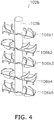
- FIG. 4 is a perspective view of the second stirrer 102b.
- the first chamber 101a and the second chamber 101b are both heat resistant receptacles of cylindrical shape having the same size.
- the first chamber 101a communicates with an upstream conduit 103 attached to the side wall at the bottom thereof, and with a connecting pipe 107 attached to the side wall at the top thereof.
- the second chamber 101b communicates with the connecting pipe 107 which is attached to the side wall at the top thereof, and with a downstream conduit 104 attached to the side wall at the bottom thereof.
- the conduit 43b corresponds to the upstream conduit 103
- the 43c corresponds to the downstream conduit 104.
- the upstream conduit 103 (conduit 43b) has a section that inclines downward towards the stirring device 100 from the fining tank 41.
- the downstream conduit 104 (conduit 43c) has a section that inclines downward towards the forming device 42 from the stirring device 100.
- the connecting pipe 107 is disposed on the horizontal.
- the first chamber 101a communicates with a first discharge pipe 110a attached to the bottom face.
- the second chamber 101b communicates with a second discharge pipe 110b attached to the side wall at the top thereof.
- the second discharge pipe 110b is installed such that the upper edge of the opening of the side wall of the second chamber 101b is positioned above the liquid level LL of the molten glass MG, and the lower edge of the opening is positioned below the liquid level LL of the molten glass MG.
- the first chamber 101a, the second chamber 101b, the first stirrer 102a, the second stirrer 102b, the upstream conduit 103, the downstream conduit 104, the connecting pipe 107, the first discharge pipe 110a, and the second discharge pipe 110b come into contact with the molten glass MG, and therefore are made of materials that can withstand the high temperature of the molten glass MG.
- these members may be made of platinum, platinum alloy, iridium, iridium alloy, or the like.
- platinum, platinum alloy, iridium, and iridium alloy are costly, it is preferable to minimize the amounts in which these are used.
- the first chamber 101a and the second chamber 101b may have multilayer structures in which a platinum layer is formed only on the inner wall thereof.
- the molten glass MG flows into the first chamber 101a in the lateral direction from the upstream conduit 103, and is stirred while being directed upward from below in the vertical direction within the first chamber 101a, then flows out in the horizontal direction from within the first chamber 101a to a connecting pipe 107.
- the molten glass MG flows into the second chamber 101b from the connecting pipe 107 in the horizontal direction, and is stirred while being directed downward from above in the vertical direction within the second chamber 101b, and then flows out in the lateral direction from the second chamber 101b to the downstream conduit 104.
- the temperature of the molten glass MG within the first chamber 101a is preferably adjusted to be 40°C-70°C higher than the temperature of the molten glass MG in the second chamber 101b.
- the first stirrer 102a is provided with a first shaft 105a of axially rotating cylindrical post shape; and first blades 106a1, 106a2, 106a3, 106a4 connected to the side wall of the first shaft 105a.
- the first shaft 105a is disposed within the first chamber 101a with the rotation axis thereof lying along the perpendicular direction.
- the first shaft 105a is disposed with the rotation axis thereof aligned with the center axis of the cylindrical shape of the first chamber 101a.
- the first blades 106a1 to 106a4 are disposed, in that order, downward from above at equidistant spacing along the axial direction of the shaft 105a.
- the first blades 106a1 to 106a4 are disposed in four tiers along the axial direction of the first shaft 105a.
- the upper end of the first shaft 105a is linked to an external motor or the like, and the first stirrer 102a can rotate with the first shaft 105a as the rotation axis.
- the second stirrer 102b has a size and configuration comparable to the first stirrer 102a, and is provided with a second shaft 105b of axially rotating cylindrical post shape; and second blades 106b1, 106b2, 106b3, 106b4, 106b5 connected to the side wall of the second shaft 105b.
- the second blades 106b1 to 106b5 are disposed in five tiers along the axial direction of the second shaft 105b.
- the upper end of the second shaft 105b is linked to an external motor or the like, and the second stirrer 102b can rotate with the second shaft 105b as the rotation axis.
- FIGS. 5 and 6 are respectively a side view and a plan view of the first blade 106a1, 106a3.
- FIGS. 7 and 8 are respectively a side view and a plan view of the first blade 106a2, 106a4.
- FIGS. 6 and 8 are plan views of the first blades 106a1 to 106a4 viewed from above along the rotation axis of the first shaft 105a.
- Each of the first blades 106a1 to 106a4 is composed of first support plates 108a directly connected to the first shaft 105a; first upper ancillary plates 109a1 arranged on the principal surface on the upper side of each first support plate 108a; and first lower ancillary plates 109a2 arranged on the principal surface on the lower side of each first support plate 108a.
- each of the first blades 106a1 to 106a4 has a configuration in which two support plates 108a are arranged perpendicular to the first shaft 105a, and two first upper ancillary plates 109a1 and two first lower ancillary plates 109a2 are respectively arranged on the principal surface on the upper side and the principal surface on the lower side of the support plates 108a.
- the first upper ancillary plates 109a1 and the first lower ancillary plates 109a2 are referred to collectively as the first ancillary plates.
- the first blades 106a1 and 106a3 have mutually identical shape, and the first blades 106a2 and 106a4 have mutually identical shape.
- the first blades 106a1, 106a3 differ from the first blades 106a2 and 106a4 in the disposition of the first support plates 108a and the first ancillary plates.
- the two first support plates 108a are attached at mutually opposite positions centered about the rotation axis of the first shaft 105a.
- the first support plates 108a are oriented with the principal surfaces thereof inclined with respect to a plane perpendicular to the rotation axis of the first shaft 105a. For this reason, when the first stirrer 102a rotates about the first shaft 105a as the rotation axis, the molten glass MG flows along the principal surfaces of the first support plates 108a, thereby giving rise to an upward or downward flow in the molten glass MG. Specifically, through axial rotation of the first stirrer 102a, the first support plates 108a push the molten glass MG upward or push it downward.
- the first blades 106a1, 106a3 and the first blades 106a2, 106a4 differ in the direction of incline of the first support plates 108a. For this reason, the flows arising in the molten glass MG due to the first blades 106a1, 106a3 and the first blades 106a2, 106a4 differ in direction from one another.
- the first ancillary plates are attached to the principal surface of the first support plate 108a in such a way that the principal surface thereof is approximately perpendicular to the principal surface of the first support plate 108a.
- the first upper ancillary plates 109a1 are attached to the principal surface on the upper side of the first support plate 108a, while the first lower ancillary plates 109a2 are attached to the principal surface on the lower side of the first support plate 108a.
- the first lower ancillary plates 109a2 are shown by broken lines.
- Each of the first ancillary plates has an inside edge 109e1 which is the edge on the side closest to the first shaft 105a, and an outside edge 109e2 which is the edge situated at the opposite side from the inside edge 109e1.
- the first ancillary plates are arranged such that, moving from the inside edge 109e1 towards the outside edge 109e2, the principal surfaces thereof diverge from a straight line 111a connecting the inside edge 109e1 and a center point 113a where the rotation axis of the first shaft 105a is positioned.
- the first upper ancillary plates 109a1 are arranged such that the principal surfaces thereof diverge from the straight lines 111a in the clockwise direction, while the first lower ancillary plates 109a2 are arranged such that the principal surfaces thereof diverge from the straight lines 111a in the counterclockwise direction.
- the first upper ancillary plates 109a1 are arranged such that the principal surfaces thereof diverge from the straight lines 111a in the counterclockwise direction
- the first lower ancillary plates 109a2 are arranged such that the principal surfaces thereof diverge from the straight lines 111a in the clockwise direction.
- the first upper ancillary plates 109a1 and the first lower ancillary plates 109a2 are arranged to extend in mutually opposite directions. Pairs of ancillary plates situated in opposition between two of the first blades 106a1 to 106a4 that are situated adjacently along the rotation axis of the first shaft 105a are arranged with the principal surfaces thereof diverging from the straight lines 111a, in the same direction as one another.
- first lower ancillary plates 109a2 of the first blade 106a1 positioned in the uppermost tier, and the first upper ancillary plates 109a1 of the first blade 106a2 positioned one tier below the first blade 106a1, are arranged such that the principal surfaces thereof diverge from the straight lines 111a in the counterclockwise direction.
- the second blades 106b1 to 106b5 have configurations comparable to the first blades 106a1 to 106a4.
- Each of the second blades 106b1 to 106b5 is composed of two second support plates 108b directly connected to a second shaft 105b; two second upper ancillary plates 109b1 arranged on the principal surface on the upper side of each second support plate 108b; and two second lower ancillary plates 109b2 arranged on the principal surface on the lower side of each second support plate 108b.
- the second upper ancillary plates 109b1 and the second lower ancillary plates 109b2 are referred to collectively as the second ancillary plates.
- the second blades 106b1, 106b3, and 106b5 have mutually identical shape, and have a configuration identical to the configuration shown in FIGS. 5 and 6 .
- the second blades 106b2, 106b4 have mutually identical shape, and have a configuration identical to the configuration shown in FIGS. 7 and 8 .
- the second support plates 108b of the second blade 106b1 positioned in the uppermost tier are disposed at substantially the same heightwise position as the lower edge of the opening of the connecting pipe 107 in the side wall of the second chamber 101b.
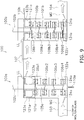
- FIG. 9 is a diagram depicting flows of molten glass MG in the stirring device 100.
- the molten glass MG having been fined in the fining tank 41 is stirred homogeneously through passage through the first stirred tank 100a and the second stirred tank 100b, and is fed to the forming device 42.
- the molten glass MG fills the interior of the first chamber 101a of the first stirred tank 100a, and the interior of the second chamber 101b of the second stirred tank 100b, to a predetermined heightwise position.
- the liquid levels LL of the molten glass MG within the first chamber 101a, the connecting pipe 107, and the second chamber 101b are at substantially identical heightwise positions. Specifically, as shown in FIG. 9 , the heightwise position of the liquid level LL of the molten glass MG is a position lower than the upper edge of the connecting pipe 107. For this reason, the spaces above the liquid level LL of the molten glass MG inside the first chamber 101a and the second chamber 101b communicate with one another via the connecting pipe 107.
- the molten glass MG inflows in the lateral direction from the upstream conduit 103 and into the first chamber 101a of the first stirred tank 100a. Within the first chamber 101a, the molten glass MG is stirred by the first stirrer 102a while being directed upward from below. The stirred molten glass MG then outflows from within the first chamber 101a to the connecting pipe 107 in the horizontal direction.
- the molten glass MG is primarily stirred by rotation of the first blades 106a1 to 106a4 of the first stirrer 102a, about the first shaft 105a as the rotation axis.
- the first ancillary plates of the first blades 106a1 to 106a4 rake the molten glass MG from the inner wall of the first chamber 101a towards the first shaft 105a, or push it from the first shaft 105a towards the inner wall of the first chamber 101a.
- first upper ancillary plates 109a1 or the first lower ancillary plates 109a2 rake the molten glass MG from the inner wall of the first chamber 101a towards the first shaft 105a, while the others push the molten glass MG from the first shaft 105a towards the inner wall of the first chamber 101a.
- the molten glass MG flows in mutually opposite directions, in the radial direction of the first shaft 105a.
- the first upper ancillary plates 109a1 of the first blade 106a1 positioned in the uppermost tier of the first shaft 105a create a flow raking the molten glass MG from the inner wall of the first chamber 101a towards the first shaft 105a, as shown in FIG. 9 .
- first lower ancillary plates 109a2 of the first blade 106a2, and the first upper ancillary plates 109a1 of the first blade 106a3, create a flow raking the molten glass MG from the inner wall of the first chamber 101a towards the first shaft 105a.
- the first lower ancillary plates 109a2 of the first blade 106a4 positioned in the lowermost tier then create a flow pushing the molten glass MG from the inner wall of the first chamber 101a towards the first shaft 105a.
- the molten glass MG flows in the direction shown by arrows 124a in FIG. 9 .
- the flow direction shown by these arrows 124a is the direction of flow in which the molten glass MG is directed from the upstream conduit 103 to inside the first chamber 101a.
- the first upper ancillary plates 109a1 of the first blade 106a1 positioned in the uppermost tier create, above the support plates 108a of the first blade 106a1, a flow moving the molten glass MG from the inner wall of the first chamber 101a towards the first shaft 105a, and create a flow ascending the molten glass MG moved by this flow along the side wall of the first shaft 105a.
- the molten glass MG having ascended into proximity with the liquid level LL of the molten glass MG then flows from the first shaft 105a towards the inner wall of the first chamber 101a, and then further descends along the inner wall of the first chamber 101a.
- the molten glass MG forms a circulating flow 123a shown by FIG. 9 .
- the flow direction of the circulating flow 123a is a flow direction such that the molten glass MG is directed from within the first chamber 101a to the connecting pipe 107. Due to this circulating flow 123a, outflow of the molten glass MG to the connecting pipe 107 without passing through the upper space 121a is minimized, and stagnation of the molten glass MG without being stirred in the upper space 121a is minimized.
- the molten glass MG flows in from the connecting pipe 107 in the horizontal direction.
- the molten glass MG is stirred by the second stirrer 102b while being directed downward from above.
- the stirred molten glass MG is then discharged from within the second chamber 101b to the downstream conduit 104 in the lateral direction.
- the flows of the molten glass MG the second stirrer 102b creates within the second chamber 101b are basically the same as the flows of the molten glass MG the first stirrer 102a creates in the first chamber 101a.
- the flows of the molten glass MG in the radial direction of the second shaft 105b are in mutually opposite directions.
- the first stirrer 102a has four tiers of the first blades 106a1 to 106a4
- the second stirrer 120b has five tiers of the second blades 106b1 to 106b5.
- the second upper ancillary plates 109b1 of the second blade 106b1 positioned in the uppermost tier of the second shaft 105b create a flow raking the molten glass MG from the inner wall of the second chamber 101b towards the second shaft 105b, as shown in FIG. 9 .
- the second lower ancillary plates 109b2 of the second blade 106b1, and the second upper ancillary plates 109b1 of the second blade 106b2 positioned one tier therebelow create a flow pushing the molten glass MG from the second shaft 105b towards the inner wall of the second chamber 101b.
- the second lower ancillary plates 109b2 of the second blade 106b2, and the second upper ancillary plates 109b1 of the second blade 106b3, create a flow raking the molten glass MG from the inner wall of the second chamber 101b towards the second shaft 105b.
- the second lower ancillary plates 109b2 of the second blade 106b5 positioned in the lowermost tier then create a flow pushing the molten glass MG from the second shaft 105b towards the inner wall of the second chamber 101b.
- the molten glass MG flows in the direction shown by arrows 124b in FIG. 9 .
- the flow direction shown by these arrows 124b is the direction in which the molten glass MG is directed from within the second chamber 101b into the downstream conduit 104. Stagnation of the molten glass MG without being stirred in the lower space 121b is minimized thereby.
- the second upper ancillary plates 109b1 of the second blade 106b1 positioned in the uppermost tier create, above the support plates 108b of the second blade 106b1, a flow moving the molten glass MG from the inner wall of the second chamber 101b towards the second shaft 105b, and create a flow ascending the molten glass MG moved by this flow along the side wall of the second shaft 105b.
- the molten glass MG having ascended into proximity with the liquid level LL of the molten glass MG then flows from the second shaft 105b towards the inner wall of the second chamber 101b, and then further descends along the inner wall of the second chamber 101b.
- the molten glass MG forms a circulating flow 123b shown by FIG. 9 .
- the flow direction of the circulating flow 123b is a flow direction such that the molten glass MG is directed from the connecting pipe 107 to within the second chamber 101b. Due to this circulating flow 123b, stagnation of the molten glass MG without being stirred in the upper space 121b is minimized.
- the stirring device 100 through axial rotation of the first stirrer 102a, between any two adjacent blades 106a1 to 106a4, the molten glass MG flowing from the upstream conduit 103 into the first chamber 101a of the first stirred tank 100a is raked from the inner wall of the first chamber 101a towards the first shaft 105a, or is pushed from the first shaft 105a towards the inner wall of the first chamber 101a.
- the flow direction of the molten glass MG in the radial direction of the first shaft 105a switches between opposite directions in each tier, moving upward from below inside the first chamber 101a. Specifically, the molten glass MG is effectively stirred by being moved in the radial direction of the first shaft 105a, while being directed progressively upward from below within the first chamber 101a.
- the molten glass MG that has been stirred within the first chamber 101a and flowed from the connecting pipe 107 into the second chamber 101b of the second stirred tank 100b is effectively stirred by being moved in the radial direction of the second shaft 105b, while being directed progressively downward from above within the second chamber 101b.
- the stirring device 100 can stir the molten glass MG in a sufficiently homogeneous fashion through rotation of the first stirrer 102a and the second stirrer 102b, in the first stirred tank 100a and the second stirred tank 100b.
- the glass manufacturing device 200 according to the present embodiment can minimize the occurrence of striae, and a high-quality glass product can be obtained.
- the first discharge pipe 110a is attached to the bottom face of the first chamber 101a of the first stirred tank 100a.
- the first discharge pipe 110a is employed to discharge the molten glass MG from the lower space 122a within the first chamber 101a.
- components of high specific gravity included in the molten glass MG may accumulate in the lower space 122a of the first chamber 101a.
- Zirconia-rich molten glass for example, is a component of high specific gravity included in the molten glass MG. Because the molten glass MG flows upward from below within the first chamber 101a, components of high specific gravity included in the molten glass MG do not readily flow into the second chamber 101b via the connecting pipe 107. For this reason, in the stirring device 100, components of high specific gravity included in the molten glass MG may accumulate in the lower space 122a at the bottom of the first chamber 101a in some cases.
- the molten glass MG that includes the components of high specific gravity and that has accumulated at the bottom of the first chamber 101a may experience concentration of the high-specific gravity components over time, and come to include components of even higher specific gravity.
- the molten glass MG including the components of high specific gravity is then supplied to the forming device 42, striae will occur in the formed glass article.
- the molten glass MG is stirred even at the bottom of the first chamber 101a, and therefore accumulation and concentration of molten glass MG including components of high specific gravity at the bottom of the first chamber 101a is minimized.
- the first discharge pipe 110a is placed on the lower space 122a of the first chamber 101a, even if molten glass MG including components of high specific gravity which flows into the chamber 101a from the upstream conduit 103 should accumulate at the bottom of the first chamber 101a, the components of high specific gravity included in the molten glass MG can be removed via the first discharge pipe 110a.
- the molten glass MG can be stirred in sufficiently homogeneous fashion in the first stirred tank 100a.
- the glass manufacturing device 200 according to the present embodiment can minimize the occurrence of striae, and a high-quality glass product can be obtained.
- the second discharge pipe 110b is attached to the second stirred tank 100b at a heightwise position in proximity to the liquid level LL of the molten glass MG within the second chamber 101b.
- the second discharge pipe 110b is employed for discharging the molten glass MG from the liquid level LL of the molten glass MG within the second chamber 101b.
- components of low specific gravity included in the molten glass MG may accumulate in proximity to the liquid level LL of the molten glass MG within the first chamber 101a, the second chamber 101b, and the connecting pipe 107.
- Silica-rich molten glass, and/or tiny air bubbles within the molten glass, and the like, for example, are components of low specific gravity included in the molten glass MG. Due to the overall flow of the molten glass MG from the first chamber 101a towards the second chamber 101b, components of low specific gravity ultimately flow into the second chamber 101b.
- the components of low specific gravity included in the molten glass MG can be removed, via the second discharge pipe 110b, from in proximity to the liquid level LL of the molten glass MG within the second chamber 101b.
- the molten glass MG flows from the second shaft 105b towards the inner wall of the second chamber 101b, at a heightwise position in proximity to the liquid level LL of the molten glass MG.
- the molten glass MG within the second chamber 101b can readily flow into the second discharge pipe 110b which is arranged on the side wall of the second chamber 101b.
- the molten glass MG can be stirred in sufficiently homogeneous fashion in the second stirred tank 100b.
- the glass manufacturing device 200 according to the present embodiment can minimize the occurrence of striae, and a high-quality glass product can be obtained.
- the molten glass MG in the lower space 122a between the first blade 106a4 positioned in the lowermost tier of the first stirrer 102a and the bottom face of the first chamber 101a flows from the inner wall of the first chamber 101a towards the first shaft 105a, as shown by the arrows 124a in FIG. 9 .
- This flow direction of the molten glass MG is a flow direction that accelerates inflow of the molten glass MG into the first chamber 101a from the upstream conduit 103.
- the molten glass MG flows from the first shaft 105a towards the inner wall of the first chamber 101a.
- This flow direction of the molten glass MG is a flow direction that minimizes inflow of the molten glass MG into the first chamber 101a from the upstream conduit 103.
- components of high specific gravity included in the molten glass MG supplied to the first stirred tank 100a inflow to the first chamber 101a along the bottom of the upstream conduit 103.
- the direction of flow of the molten glass MG in the lower space 122a of the first chamber 101a is the opposite direction from the arrows 124a in FIG. 9
- the components of high specific gravity flowing along the bottom of the upstream conduit 103 would hinder inflow to the first chamber 101a.
- the components of high specific gravity included in the molten glass MG would readily be retained at the bottom of the upstream conduit 103, just short of the first chamber 101a. In this case, there would be a risk that components of high specific gravity, having accumulated and concentrated at the bottom of the upstream conduit 103, would become entrained in the flow of the molten glass MG, and pass through the stirring device 100. This could cause striae to occur in the glass ribbon GR formed by the forming device 42.
- the molten glass MG flowing through the upstream conduit 103 experiences accelerated inflow to the lower space 122a within the first chamber 101a, while inflow to the space between the first blade 106a4 positioned in the lowermost tier and the first blade 106a3 positioned one tier thereabove is minimized. For this reason, initially, the molten glass MG flowing through the upstream conduit 103 is supplied to the lower space 122a within the first chamber 101a, and is next stirred in succession by the first blades 106a4, 106a3, 106a2, and 106a1, and thereafter fed to the connecting pipe 107.
- the molten glass MG can be stirred in sufficiently homogeneous fashion in the first stirred tank 100a.
- the glass manufacturing device 200 according to the present embodiment can minimize the occurrence of striae, and a high-quality glass product can be obtained.
- the molten glass MG in the lower space 122b between the second blade 106b5 positioned in the lowermost tier of the second stirrer 102b and the bottom face of the second chamber 101b flows from the second shaft 105b towards the inner wall of the second chamber 101b, as shown by the arrows 124b in FIG. 9 .
- This flow direction of the molten glass MG is a flow direction that accelerates outflow of the molten glass MG into the downstream conduit 104 from within the second chamber 101b.
- the molten glass MG flows from the inner wall of the second chamber 101b towards the second shaft 105b.
- This flow direction of the molten glass MG is a flow direction that minimizes outflow of the molten glass MG into the downstream conduit 104 from within the second chamber 101b.
- the molten glass MG can be stirred in sufficiently homogeneous fashion in the second stirred tank 100b.
- the glass manufacturing device 200 according to the present embodiment can minimize the occurrence of striae, and a high-quality glass product can be obtained.
- the stirring device 100 in the upper space 121a lying between the liquid level LL of the molten glass MG and the first blade 106a1 positioned in the uppermost tier within the first chamber 101a of the first stirred tank 100a, the molten glass MG forms an ascending flow at the perimeter of the first shaft 105a, while the molten glass MG forms a descending flow along the inner wall of the first chamber 101a. For this reason, outflow of the molten glass MG to the connecting pipe 107 without having passed through the upper space 121a is minimized, and stagnation of the molten glass MG without being stirred in the upper space 121a is minimized.
- this circulating flow 123a has a speed such that ripples do not form on liquid level LL of the molten glass MG; or in more specific terms, a speed such that air in proximity to the liquid level LL is not entrained.
- the spacing between the first blade 106a1 and the liquid level LL of the molten glass MG is preferably from 50 mm to 200 mm; and moreover that the temperature of the molten glass MG in the upper space 121a is preferably from 1400°C to 1550°C, and the viscosity is from 2400 to 450 Poise.
- the molten glass MG can be stirred in sufficiently homogeneous fashion in the first stirred tank 100a.
- the glass manufacturing device 200 according to the present embodiment can minimize the occurrence of striae, and a high-quality glass product can be obtained.
- the stirring device 100 in the upper space 121b lying between the liquid level LL of the molten glass MG and the second blade 106b1 positioned in the uppermost tier within the second chamber 101b of the second stirred tank 100b, the molten glass MG forms an ascending flow at the perimeter of the second shaft 105b, while the molten glass MG forms a descending flow along the inner wall of the second chamber 101b. For this reason, stagnation of the molten glass MG without being stirred in the upper space 121b is minimized.
- a circulating flow 123b of the molten glass MG is formed in the upper space 121b. For this reason, stagnation of the molten glass MG in proximity to the liquid level LL of the molten glass MG is minimized. In preferred practice, this circulating flow 123b has a speed such that ripples do not form on liquid level LL of the molten glass MG.
- the spacing between the second blade 106b1 and the liquid level LL of the molten glass MG is preferably from 50 mm to 200 mm; and moreover that the temperature/viscosity of the molten glass MG in the upper space 121b is preferably from 2400 Poise/1400°C to 450 Poise/1550°C.
- the molten glass MG can be stirred in sufficiently homogeneous fashion in the second stirred tank 100b.
- the glass manufacturing device 200 according to the present embodiment can minimize the occurrence of striae, and a high-quality glass product can be obtained.
- the first blades 106a1 to 106a4 are disposed in four tiers on the first shaft 105a; and in the second stirrer 102b, the second blades 106b1 to 106b5 are disposed in five tiers on the second shaft 105b.
- the number of tiers of the first blades 106a1 to 106a4 and the second blades 106b1 to 106b5 may be determined appropriately in consideration of the size of the first chamber 101a and the second chamber 101b, and/or the length of the first shaft 105a and the second shaft 105b, and so on, provided that the flow directions of the molten glass MG discussed previously are assured.
- the spacing between two of the blades situated adjacently in the axial direction along the first shaft 105a and the second shaft 105b may be determined appropriately in consideration of the size of the first chamber 101a and the second chamber 101b, and so on.
- each of the first blades 106a1 to 106a4 is composed of two first support plates 108a, but could instead be composed of three or more first support plates 108a.
- each of the second blades 106b1 to 106b5 is composed of two second support plates 108b, but could instead be composed of three or more second support plates 108b.
- FIG. 10 shows a perspective view of a first blade 206 having three first support plates 208. The present modification example is applicable to the second blades 106b1 to 106b5 of the second stirrer 102b as well.
- the first stirrer 102a has the first blades 106a1 to 106a4.
- Through-holes 112a may be formed in the principal surfaces of the first support plates 108a of the first blades 106a1 to 106a4.
- FIG. 11 is a plan view of a first blade 106a1, 106a3 having through-holes 112a.
- a portion of the molten glass MG can pass through the through-holes 112a. Passage of a portion of the molten glass MG through the through-holes 112a creates an upward or downward flow of the molten glass MG.
- the through-holes 112a create a flow in the axial direction of the first shaft 105a, in addition to the flow in the radial direction of the first shaft 105a produced by the first ancillary plates, and the flow in the axial direction of the first shaft 105a produced by inclination of the first support plates 108a. For this reason, within the first chamber 101a, more complex flows arise in the molten glass MG, and higher stirring effect can be obtained.
- the resistance the first blades 106a1 to 106a4 receive from the molten glass MG during rotation of the first stirrer 102a is lower, and less power is needed to create the intended flow in the molten glass MG.
- the present modification example is applicable to the second blades 106b1 to 106b5 of the second stirrer 102b as well.
- the second discharge pipe 110b is positioned such that the upper edge of the opening of the side wall of the second chamber 101b is above the liquid level of the molten glass MG, and the lower edge of the opening is positioned below the liquid level of the molten glass MG.
- the second discharge pipe 110b may be arranged so that the liquid level of the molten glass MG is positioned above the upper edge of the opening of the side wall of the second chamber 101b.
- the second discharge pipe 110b may be arranged at a heightwise position such that components of low specific gravity present in proximity to the liquid level LL of the molten glass MG within the first chamber 101a can inflow to the second chamber 101b through the connecting pipe 107.
- the molten glass MG employed in the glass manufacturing device 200 is alkali-free glass or low-alkali glass; and in the stirring device 100, the molten glass MG is stirred in a temperature range of 1400°C to 1550°C.
- the molten glass MG employed in the glass manufacturing device 200 may be a molten glass to which a larger alkali component has been added, as compared with the molten glass MG used in the present embodiment. In this case, in the stirring device 100, the molten glass MG would be stirred in a temperature range of 1300°C to 1400°C.
- the first blades 106a1 to 106a4 are arranged such that the two first support plates 108a are orthogonal to the axial direction of the first shaft 105a.
- the first support plates 108a may be attached to the first shaft 105a in an inclined state with respect to a plane orthogonal to the first shaft 105a.
- the present modification example is applicable to the second blades 106b1 to 106b5 of the second stirrer 102b as well.
- the first shaft 105a is disposed with the rotation axis thereof coincident with the center axis of the cylindrical shape of the first chamber 101a. However, the first shaft 105a is disposed with the rotation axis thereof away from the center axis of the cylindrical shape of the first chamber 101a.
- the second stirrer 102b has the same size as the first stirrer 102a, but may have a different size than the first stirrer 102a.
- the second stirrer 102b may have a smaller size than the first stirrer 102a.
Description
- The present invention relates to a method of manufacturing glass, and to a stirring device.
- In processes for high-volume production of glass articles such as plate glass, a glass material is heated to produce molten glass, and the molten glass so produced is formed to manufacture glass articles such as plate glass. If the molten glass is heterogeneous, striae may form in the glass articles. Striae are zones of striated appearance differing in refractive index and/or specific gravity from the surrounding area; in optical components such as lenses, substrates for liquid crystal displays (LCD), and other such applications, there is a need to rigorously eliminate them from the glass articles. Stirring of the molten glass by a stirring device is performed in order to prevent striae. A typical stirring device is provided with a chamber of round cylindrical shape, and a stirrer. The stirrer has a shaft serving as a rotation axis, and blades connected to the side wall of the shaft. In the stirring device, molten glass is supplied into a chamber in which the stirrer is disposed, and the molten glass is stirred by axially rotating blades, rendering the molten glass homogeneous.
- Patent Document 1 (Japanese Unexamined Patent Application Publication
2001-72426 - Patent Document 2 (Japanese Unexamined Patent Application Publication
2007-204357 -
US 2009/0282872 A1 discloses a method of manufacturing glass, comprising a melting step for melting a glass material and obtaining molten glass; a stirring step for stirring the molten glass obtained in the melting step; and a forming step for forming glass from the molten glass stirred in the stirring step; wherein the stirring step comprises a first stirring step in which the molten glass is stirred while being directed upward from below in the interior of a first stirred tank, and a second stirring step in which the molten glass stirred in the first stirring step is stirred while being directed downward from above in the interior of a second stirred tank; the first stirred tank comprises a first chamber a first stirrer for stirring the molten glass in the first chamber, the first chamber communicating with an upstream conduit attached to the side wall at the bottom of the first chamber and; the upstream conduit being configured such that the molten glass flows into the first chamber in the lateral direction; the second stirred tank comprises a second chamber and a second stirrer for stirring the molten glass in the second chamber, the second chamber communicating with a downstream conduit attached to the side wall at the bottom of the second chamber, and the downstream conduit discharging the stirred molten glass from within the second chamber in the lateral direction; the upper lateral part of the first stirred tank is connected by a connecting pipe to the upper lateral part of the second stirred tank; and the molten glass is transferred from the first stirred tank to the second stirred tank via the connecting pipe. - Various stirring devices have been proposed in the prior art, with the object of stirring molten glass. However, these prior art stirring devices lack sufficient capability to homogenize molten glass in a stable manner. Therefore, there exists a need for a stirring device that can homogenize in a more stable manner molten glass that is supplied to a glass forming step.
- With the foregoing in view, an object of the present invention is to provide a method of manufacturing glass and a stirring device, whereby molten glass can be stirred in a more homogeneous manner.
- A method of manufacturing glass according to the present invention comprises: a melting step for melting a glass material and obtaining molten glass; a stirring step for stirring the molten glass obtained in the melting step; and a forming step for forming glass from the molten glass stirred in the stirring step. The stirring step comprises a first stirring step and a second stirring step. In the first stirring step, the molten glass is stirred while being directed upward from below in the interior of a first stirred tank. In the second stirring step, the molten glass stirred in the first stirring step is stirred while being directed downward from above in the interior of a second stirred tank. The first stirred tank comprises a first chamber, a first stirrer for stirring the molten glass in the first chamber, and a first discharge pipe capable of discharging the molten glass from the bottom of the first chamber. The second stirred tank comprises a second chamber, a second stirrer for stirring the molten glass in the second chamber, and a second discharge pipe capable of discharging the molten glass from the liquid level of the molten glass in the second chamber. The upper lateral part of the first stirred tank is connected by a connecting pipe to the upper lateral part of the second stirred tank. The molten glass is transferred from the first stirred tank to the second stirred tank via the connecting pipe.
- In the method of manufacturing glass according to the present invention, in the stirring step, the molten glass obtained in the melting step is stirred in the first stirred tank, and thereafter stirred further in the second stirred tank. In the first chamber of the first stirred tank, the molten glass is stirred while being directed upward from below. The molten glass stirred in the first stirred tank is fed to the second stirred tank via the connecting pipe. In the second chamber of the second stirred tank, the molten glass is stirred while being directed downward from above. In the stirring step, components of high specific gravity (zirconia-rich molten glass and the like) included in the molten glass may accumulate at the bottom of the first chamber in some instances. Because the molten glass ascends within the first chamber and is fed to the second chamber, components of high specific gravity having accumulated at the bottom of the first chamber do not readily flow into the second chamber. And the first discharge pipe is attached to the bottom face of the first chamber. Therefore, components of high specific gravity having accumulated at the bottom of the first chamber can be discharged from the first chamber via the discharge pipe. In the first chamber, components of low specific gravity (silica-rich molten glass, and/or tiny bubbles in the molten glass, and the like) included in the molten glass may accumulate in proximity to the liquid level in some instances. Components of low specific gravity within the first chamber are fed, together with the molten glass, to the second chamber via the connecting pipe connecting the first chamber and the second chamber. Specifically, components of low specific gravity included in the molten glass ultimately accumulate in proximity to the liquid level of the molten glass within the second chamber. And the second discharge tube is attached to the second chamber at a heightwise position in proximity to the liquid level. Therefore, the components of low specific gravity having accumulated in proximity to the liquid level of the molten glass can be discharged from the second chamber via the second discharge pipe.
- It follows from the above that, in the stirring step of the method for manufacturing glass according to the present invention, components of high specific gravity included in the molten glass can be efficiently eliminated through the first discharge pipe, and components of low specific gravity included in the molten glass can be efficiently eliminated through the second discharge pipe. If components of different specific gravities included in the molten glass accumulate and become concentrated in the stirring step, and are then fed to the forming step, striae can occur in the formed glass. With the method for manufacturing glass according to the present invention, components of different specific gravities included in the molten glass can be readily eliminated, and therefore the molten glass can be stirred homogeneously in the first stirred tank and the second stirred tank, and the occurrence of striae in the glass can be suppressed.
- A method of manufacturing glass according to the present invention comprises: a melting step for melting a glass material and obtaining molten glass; a stirring step for stirring the molten glass obtained in the melting step; and a forming step for forming glass from the molten glass stirred in the stirring step. The stirring step comprises a first stirring step and a second stirring step. In the first stirring step, the molten glass is stirred while being directed upward from below in the interior of a first stirred tank. In the second stirring step, the molten glass stirred in the first stirring step is stirred while being directed downward from above in the interior of a second stirred tank. The first stirred tank comprises a first chamber, a first stirrer for stirring the molten glass in the first chamber, and a first discharge pipe capable of discharging the molten glass from the bottom of the first chamber. The second stirred tank comprises a second chamber, a second stirrer for stirring the molten glass in the second chamber, and a second discharge pipe capable of discharging the molten glass from the liquid level of the molten glass in the second chamber. The upper lateral part of the first stirred tank is connected by a connecting pipe to the upper lateral part of the second stirred tank. The molten glass is transferred from the first stirred tank to the second stirred tank via the connecting pipe. In the second stirring step, the second stirrer rotates about a second shaft as the rotation axis, whereby second ancillary plates create, in the molten glass, a flow in the radial direction of the second shaft, and the second ancillary plates positioned between second support plates of second blades disposed in two adjacent tiers create, in the molten glass, a flow in the same direction. In the second stirring step, the second ancillary plates arranged on the upper principal surfaces of the second support plates of the second blade positioned in the uppermost tier create, above the second support plates of the second blade positioned in the uppermost tier, a first flow moving the molten glass from an inner wall of the second chamber towards the second shaft, and create a second flow ascending the molten glass moved by the first flow along a side wall of the second shaft.
- The stirring device according to the present invention is a stirring device for stirring molten glass, comprising a first stirred tank, a second stirred tank, and a connecting pipe. The first stirred tank has a first chamber, a first stirrer for stirring the molten glass in the first chamber, and a first discharge pipe capable of discharging the molten glass from the bottom of the first chamber. The second stirred tank has a second chamber, a second stirrer for stirring the molten glass in the second chamber, and a second discharge pipe capable of discharging the molten glass from the liquid level of the molten glass in the second chamber. The connecting pipe connects the upper lateral part of the first stirred tank to the upper lateral part of the second stirred tank. The connecting pipe transfers the molten glass from the first stirred tank to the second stirred tank via the connecting pipe. In the interior of the first stirred tank, the molten glass is stirred while being directed upward from below. In the interior of the second stirred tank, the molten glass stirred by the first stirrer is stirred while being directed downward from above.
- The method of manufacturing glass and the stirring device according to the present invention can stir molten glass in a more homogeneous manner.
-
-
FIG. 1 is a schematic showing an example of a configuration of a glass manufacturing device according to an embodiment; -
FIG. 2 is a side view of the stirring device according to the embodiment; -
FIG. 3 is a perspective view of a first stirrer according to the embodiment; -
FIG. 4 is a perspective view of a second stirrer according to the embodiment; -
FIG. 5 is a side view of a first blade of the first stirrer according to the embodiment; -
FIG. 6 is a plan view of a first blade of the first stirrer according to the embodiment; -
FIG. 7 is a side view of a first blade of the first stirrer according to the embodiment; -
FIG. 8 is a plan view of a first blade of the first stirrer according to the embodiment; -
FIG. 9 is a diagram depicting flows of molten glass in the stirring device according to the embodiment; -
FIG. 10 is a perspective view of a first blade of a first stirrer according to a modification example B of the embodiment; and -
FIG. 11 is a plan view of a first blade of a first stirrer according to a modification example C of the embodiment. - An embodiment of a glass manufacturing device employing the method of manufacturing glass and the stirring device according to the present invention will be described with reference to the drawings.
FIG. 1 is a generic view showing an example of a configuration of aglass manufacturing device 200 according to the present embodiment. Theglass manufacturing device 200 is provided with amelting tank 40; afining tank 41; astirring device 100; a formingdevice 42; andconduits melting tank 40 flows through the conduit 43a and into the finingtank 41; the MG having been fined in thefining tank 41 flows through theconduit 43b and into the stirringdevice 100; and the MG having been stirred homogeneously by the stirringdevice 100, flows through theconduit 43c and into the formingdevice 42, where a glass ribbon GR is formed from the molten glass MG by the formingdevice 42 employing a downdraw method. - Heating means such as a burner or the like (not shown) is arranged in the
melting tank 40, so that a glass material can be melted to obtain the molten glass MG. The glass material may be adjusted appropriately so that glass having the desired physical properties can be obtained. For example, the glass material may be prepared so as to obtain glass having substantially the following composition, expressed as mass percent.SiO2 57-65% Al2O3 15-19% B2O3 8-13% MgO 1-3% CaO 4-7% SrO 1-4% BaO 0-2% Na2O 0-1% K2O 0-1% As2O3 0-1% Sb2O3 0-1% SnO2 0-1% Fe2O3 0-1% ZrO2 0-1% - Herein, "substantially" means that the presence of trace amounts of components within a range of less than 0.1 mass% is permissible. Consequently, it is permissible for the glass having the aforedescribed composition to have admixed therein trace amounts of other components, within a range of less than 0.1 mass%. The proportions of Fe2O3, As2O3, Sb2O3, and SnO2 in the aforedescribed composition are values derived through conversion, treating all of the components Fe, As, Sb, or Sn having plural valence as Fe2O3, As2O3, Sb2O3, or SnO2.
- In the present embodiment, the glass material prepared in the aforedescribed manner is charged to the
melting tank 40. In themelting tank 40, the glass material is melted at a temperature set according to the composition thereof, for example, 1500°C or above, to obtain the molten glass MG. - The molten glass MG obtained in the
melting tank 40 passes from themelting tank 40 through the conduit 43a and flows into the finingtank 41. Heating means (not shown) comparable to that of themelting tank 40 is arranged in thefining tank 41. The finingtank 41 further raises the temperature of the molten glass MG to bring about fining. In specific terms, in thefining tank 41, the temperature of the molten glass MG is raised to 1550°C or above, and further to 1600°C or above. Fining of the molten glass MG is brought about by the rise in temperature, removing tiny bubbles included in the molten glass MG. - The fined molten glass MG in the
fining tank 41 passes from the finingtank 41 through theconduit 43b and flows into the stirringdevice 100. During passage through theconduit 43b, the molten glass MG cools down. In thestirring device 100, the molten glass MG is stirred and homogenized at a lower temperature than in thefining tank 41. In specific terms, in thestirring device 100, the molten glass MG is stirred while adjusted to within a temperature range of 1400°C-1550°C. The viscosity of the molten glass MG stirred by the stirringdevice 100 is 450 poise-2400 poise. - The molten glass MG having been homogenized by the stirring
device 100 passes from the stirringdevice 100 through theconduit 43c and flows into the formingdevice 42. During passage through theconduit 43c, the molten glass MG cools down again, cooling to a temperature of about 1200°C, suitable for forming. In the formingdevice 42, the molten glass MG is formed by the downdraw method. In specific terms, the molten glass MG flowing into the formingdevice 42 spills out over the top of the formingdevice 42 and flows downward along the side wall of the formingdevice 42. A glass ribbon GR is thereby continuously formed from the bottom edge of the formingdevice 42. The glass ribbon GR gradually cools as it moves downward, and finally is cut into plate glass of the desired size. -
FIG. 2 is a side view of the stirringdevice 100. The stirringdevice 100 is primarily constituted by a first stirredtank 100a and a second stirredtank 100b. The first stirredtank 100a is primarily constituted by afirst chamber 101a, and afirst stirrer 102a housed inside thefirst chamber 101a. The second stirredtank 100b is primarily constituted by asecond chamber 101b, and asecond stirrer 102b housed inside thesecond chamber 101b.FIG. 3 is a perspective view of thefirst stirrer 102a, andFIG. 4 is a perspective view of thesecond stirrer 102b. - The
first chamber 101a and thesecond chamber 101b are both heat resistant receptacles of cylindrical shape having the same size. Thefirst chamber 101a communicates with anupstream conduit 103 attached to the side wall at the bottom thereof, and with a connectingpipe 107 attached to the side wall at the top thereof. Thesecond chamber 101b communicates with the connectingpipe 107 which is attached to the side wall at the top thereof, and with adownstream conduit 104 attached to the side wall at the bottom thereof. InFIG. 1 , theconduit 43b corresponds to theupstream conduit 103, and the 43c corresponds to thedownstream conduit 104. The upstream conduit 103 (conduit 43b) has a section that inclines downward towards the stirringdevice 100 from the finingtank 41. The downstream conduit 104 (conduit 43c) has a section that inclines downward towards the formingdevice 42 from the stirringdevice 100. The connectingpipe 107 is disposed on the horizontal. - The
first chamber 101a communicates with afirst discharge pipe 110a attached to the bottom face. Thesecond chamber 101b communicates with asecond discharge pipe 110b attached to the side wall at the top thereof. Thesecond discharge pipe 110b is installed such that the upper edge of the opening of the side wall of thesecond chamber 101b is positioned above the liquid level LL of the molten glass MG, and the lower edge of the opening is positioned below the liquid level LL of the molten glass MG. - In the present embodiment, the
first chamber 101a, thesecond chamber 101b, thefirst stirrer 102a, thesecond stirrer 102b, theupstream conduit 103, thedownstream conduit 104, the connectingpipe 107, thefirst discharge pipe 110a, and thesecond discharge pipe 110b come into contact with the molten glass MG, and therefore are made of materials that can withstand the high temperature of the molten glass MG. For example, these members may be made of platinum, platinum alloy, iridium, iridium alloy, or the like. However, because platinum, platinum alloy, iridium, and iridium alloy are costly, it is preferable to minimize the amounts in which these are used. For example, thefirst chamber 101a and thesecond chamber 101b may have multilayer structures in which a platinum layer is formed only on the inner wall thereof. - In the first stirred
tank 100a, the molten glass MG flows into thefirst chamber 101a in the lateral direction from theupstream conduit 103, and is stirred while being directed upward from below in the vertical direction within thefirst chamber 101a, then flows out in the horizontal direction from within thefirst chamber 101a to a connectingpipe 107. Then, in the second stirredtank 100b, the molten glass MG flows into thesecond chamber 101b from the connectingpipe 107 in the horizontal direction, and is stirred while being directed downward from above in the vertical direction within thesecond chamber 101b, and then flows out in the lateral direction from thesecond chamber 101b to thedownstream conduit 104. The temperature of the molten glass MG within thefirst chamber 101a is preferably adjusted to be 40°C-70°C higher than the temperature of the molten glass MG in thesecond chamber 101b. - As shown in
FIG. 3 , thefirst stirrer 102a is provided with afirst shaft 105a of axially rotating cylindrical post shape; and first blades 106a1, 106a2, 106a3, 106a4 connected to the side wall of thefirst shaft 105a. Thefirst shaft 105a is disposed within thefirst chamber 101a with the rotation axis thereof lying along the perpendicular direction. Thefirst shaft 105a is disposed with the rotation axis thereof aligned with the center axis of the cylindrical shape of thefirst chamber 101a. The first blades 106a1 to 106a4 are disposed, in that order, downward from above at equidistant spacing along the axial direction of theshaft 105a. Specifically, on thefirst stirrer 102a, the first blades 106a1 to 106a4 are disposed in four tiers along the axial direction of thefirst shaft 105a. The upper end of thefirst shaft 105a is linked to an external motor or the like, and thefirst stirrer 102a can rotate with thefirst shaft 105a as the rotation axis. - As shown in
FIG. 4 , thesecond stirrer 102b has a size and configuration comparable to thefirst stirrer 102a, and is provided with asecond shaft 105b of axially rotating cylindrical post shape; and second blades 106b1, 106b2, 106b3, 106b4, 106b5 connected to the side wall of thesecond shaft 105b. Specifically, on thesecond stirrer 102b, the second blades 106b1 to 106b5 are disposed in five tiers along the axial direction of thesecond shaft 105b. The upper end of thesecond shaft 105b is linked to an external motor or the like, and thesecond stirrer 102b can rotate with thesecond shaft 105b as the rotation axis. - Next, the configuration of the first blades 106a1 to 106a4 will be described while making reference to
FIGS. 5 to 8 .FIGS. 5 and 6 are respectively a side view and a plan view of the first blade 106a1, 106a3.FIGS. 7 and 8 are respectively a side view and a plan view of the first blade 106a2, 106a4.FIGS. 6 and8 are plan views of the first blades 106a1 to 106a4 viewed from above along the rotation axis of thefirst shaft 105a. Each of the first blades 106a1 to 106a4 is composed offirst support plates 108a directly connected to thefirst shaft 105a; first upper ancillary plates 109a1 arranged on the principal surface on the upper side of eachfirst support plate 108a; and first lower ancillary plates 109a2 arranged on the principal surface on the lower side of eachfirst support plate 108a. In the present embodiment, each of the first blades 106a1 to 106a4 has a configuration in which twosupport plates 108a are arranged perpendicular to thefirst shaft 105a, and two first upper ancillary plates 109a1 and two first lower ancillary plates 109a2 are respectively arranged on the principal surface on the upper side and the principal surface on the lower side of thesupport plates 108a. Herein, the first upper ancillary plates 109a1 and the first lower ancillary plates 109a2 are referred to collectively as the first ancillary plates. In the present embodiment, the first blades 106a1 and 106a3 have mutually identical shape, and the first blades 106a2 and 106a4 have mutually identical shape. The first blades 106a1, 106a3 differ from the first blades 106a2 and 106a4 in the disposition of thefirst support plates 108a and the first ancillary plates. - The two
first support plates 108a are attached at mutually opposite positions centered about the rotation axis of thefirst shaft 105a. Thefirst support plates 108a are oriented with the principal surfaces thereof inclined with respect to a plane perpendicular to the rotation axis of thefirst shaft 105a. For this reason, when thefirst stirrer 102a rotates about thefirst shaft 105a as the rotation axis, the molten glass MG flows along the principal surfaces of thefirst support plates 108a, thereby giving rise to an upward or downward flow in the molten glass MG. Specifically, through axial rotation of thefirst stirrer 102a, thefirst support plates 108a push the molten glass MG upward or push it downward. In the present embodiment, the first blades 106a1, 106a3 and the first blades 106a2, 106a4 differ in the direction of incline of thefirst support plates 108a. For this reason, the flows arising in the molten glass MG due to the first blades 106a1, 106a3 and the first blades 106a2, 106a4 differ in direction from one another. - The first ancillary plates are attached to the principal surface of the
first support plate 108a in such a way that the principal surface thereof is approximately perpendicular to the principal surface of thefirst support plate 108a. The first upper ancillary plates 109a1 are attached to the principal surface on the upper side of thefirst support plate 108a, while the first lower ancillary plates 109a2 are attached to the principal surface on the lower side of thefirst support plate 108a. InFIGS. 6 and8 , the first lower ancillary plates 109a2 are shown by broken lines. - Each of the first ancillary plates has an inside edge 109e1 which is the edge on the side closest to the
first shaft 105a, and an outside edge 109e2 which is the edge situated at the opposite side from the inside edge 109e1. As shown inFIGS. 6 and8 , the first ancillary plates are arranged such that, moving from the inside edge 109e1 towards the outside edge 109e2, the principal surfaces thereof diverge from astraight line 111a connecting the inside edge 109e1 and acenter point 113a where the rotation axis of thefirst shaft 105a is positioned. In specific terms, as shown inFIG. 6 , for the blades 106a1, 106a3, the first upper ancillary plates 109a1 are arranged such that the principal surfaces thereof diverge from thestraight lines 111a in the clockwise direction, while the first lower ancillary plates 109a2 are arranged such that the principal surfaces thereof diverge from thestraight lines 111a in the counterclockwise direction. On the other hand, as shown inFIG. 8 , for the blades 106a2, 106a4, the first upper ancillary plates 109a1 are arranged such that the principal surfaces thereof diverge from thestraight lines 111a in the counterclockwise direction, while the first lower ancillary plates 109a2 are arranged such that the principal surfaces thereof diverge from thestraight lines 111a in the clockwise direction. Specifically, in each of the blades 106a1 to 106a4, the first upper ancillary plates 109a1 and the first lower ancillary plates 109a2 are arranged to extend in mutually opposite directions. Pairs of ancillary plates situated in opposition between two of the first blades 106a1 to 106a4 that are situated adjacently along the rotation axis of thefirst shaft 105a are arranged with the principal surfaces thereof diverging from thestraight lines 111a, in the same direction as one another. For example, the first lower ancillary plates 109a2 of the first blade 106a1 positioned in the uppermost tier, and the first upper ancillary plates 109a1 of the first blade 106a2 positioned one tier below the first blade 106a1, are arranged such that the principal surfaces thereof diverge from thestraight lines 111a in the counterclockwise direction. - The second blades 106b1 to 106b5 have configurations comparable to the first blades 106a1 to 106a4. Each of the second blades 106b1 to 106b5 is composed of two second support plates 108b directly connected to a
second shaft 105b; two second upper ancillary plates 109b1 arranged on the principal surface on the upper side of each second support plate 108b; and two second lower ancillary plates 109b2 arranged on the principal surface on the lower side of each second support plate 108b. Herein, the second upper ancillary plates 109b1 and the second lower ancillary plates 109b2 are referred to collectively as the second ancillary plates. In the present embodiment, the second blades 106b1, 106b3, and 106b5 have mutually identical shape, and have a configuration identical to the configuration shown inFIGS. 5 and 6 . The second blades 106b2, 106b4 have mutually identical shape, and have a configuration identical to the configuration shown inFIGS. 7 and 8 . The second support plates 108b of the second blade 106b1 positioned in the uppermost tier are disposed at substantially the same heightwise position as the lower edge of the opening of the connectingpipe 107 in the side wall of thesecond chamber 101b. - The operation of the stirring
device 100 according to the present embodiment is now described.FIG. 9 is a diagram depicting flows of molten glass MG in thestirring device 100. The molten glass MG having been fined in thefining tank 41 is stirred homogeneously through passage through the first stirredtank 100a and the second stirredtank 100b, and is fed to the formingdevice 42. In thestirring device 100, the molten glass MG fills the interior of thefirst chamber 101a of the first stirredtank 100a, and the interior of thesecond chamber 101b of the second stirredtank 100b, to a predetermined heightwise position. In the present embodiment, the liquid levels LL of the molten glass MG within thefirst chamber 101a, the connectingpipe 107, and thesecond chamber 101b are at substantially identical heightwise positions. Specifically, as shown inFIG. 9 , the heightwise position of the liquid level LL of the molten glass MG is a position lower than the upper edge of the connectingpipe 107. For this reason, the spaces above the liquid level LL of the molten glass MG inside thefirst chamber 101a and thesecond chamber 101b communicate with one another via the connectingpipe 107. - The molten glass MG inflows in the lateral direction from the
upstream conduit 103 and into thefirst chamber 101a of the first stirredtank 100a. Within thefirst chamber 101a, the molten glass MG is stirred by thefirst stirrer 102a while being directed upward from below. The stirred molten glass MG then outflows from within thefirst chamber 101a to the connectingpipe 107 in the horizontal direction. - Within the
first chamber 101a, the molten glass MG is primarily stirred by rotation of the first blades 106a1 to 106a4 of thefirst stirrer 102a, about thefirst shaft 105a as the rotation axis. In specific terms, the first ancillary plates of the first blades 106a1 to 106a4 rake the molten glass MG from the inner wall of thefirst chamber 101a towards thefirst shaft 105a, or push it from thefirst shaft 105a towards the inner wall of thefirst chamber 101a. In the present embodiment, in each of the first blades 106a1 to 106a4, either the first upper ancillary plates 109a1 or the first lower ancillary plates 109a2 rake the molten glass MG from the inner wall of thefirst chamber 101a towards thefirst shaft 105a, while the others push the molten glass MG from thefirst shaft 105a towards the inner wall of thefirst chamber 101a. Specifically, above thefirst support plates 108a and below thefirst support plates 108a of each of the first blades 106a1 to 106a4, the molten glass MG flows in mutually opposite directions, in the radial direction of thefirst shaft 105a. For any two of the first blades 106a1 to 106a4 situated adjacently along the rotation axis of thefirst shaft 105a, the principal surfaces of the first lower ancillary plates 109a2 positioned in a tier above, and those of the first upper ancillary plates 109a1 positioned in the tier therebelow, diverge in the same direction from thestraight lines 111a. For this reason, the flows of molten glass MG arising in the radial direction of thefirst shaft 105a due to a pair of mutually opposed ancillary plates 109a will move in the same direction. - In the present embodiment, through rotation of the
first stirrer 102a in the clockwise direction as seen from above, the first upper ancillary plates 109a1 of the first blade 106a1 positioned in the uppermost tier of thefirst shaft 105a create a flow raking the molten glass MG from the inner wall of thefirst chamber 101a towards thefirst shaft 105a, as shown inFIG. 9 . For this reason, the first lower ancillary plates 109a2 of the first blade 106a1, and the first upper ancillary plates 109a1 of the first blade 106a2 positioned one tier below, create a flow pushing the molten glass MG from thefirst shaft 105a towards the inner wall of thefirst chamber 101a. Likewise, the first lower ancillary plates 109a2 of the first blade 106a2, and the first upper ancillary plates 109a1 of the first blade 106a3, create a flow raking the molten glass MG from the inner wall of thefirst chamber 101a towards thefirst shaft 105a. The first lower ancillary plates 109a2 of the first blade 106a4 positioned in the lowermost tier then create a flow pushing the molten glass MG from the inner wall of thefirst chamber 101a towards thefirst shaft 105a. Specifically, in alower space 122a between the first blade 106a4 positioned in the lowermost tier and the bottom face of thefirst chamber 101a, the molten glass MG flows in the direction shown byarrows 124a inFIG. 9 . The flow direction shown by thesearrows 124a is the direction of flow in which the molten glass MG is directed from theupstream conduit 103 to inside thefirst chamber 101a. - In the present embodiment, through axial rotation of the
first stirrer 102a, the first upper ancillary plates 109a1 of the first blade 106a1 positioned in the uppermost tier create, above thesupport plates 108a of the first blade 106a1, a flow moving the molten glass MG from the inner wall of thefirst chamber 101a towards thefirst shaft 105a, and create a flow ascending the molten glass MG moved by this flow along the side wall of thefirst shaft 105a. The molten glass MG having ascended into proximity with the liquid level LL of the molten glass MG then flows from thefirst shaft 105a towards the inner wall of thefirst chamber 101a, and then further descends along the inner wall of thefirst chamber 101a. Specifically, in anupper space 121a between the first blade 106a1 positioned in the uppermost tier, and the liquid level LL of the molten glass MG, the molten glass MG forms a circulatingflow 123a shown byFIG. 9 . In proximity to the liquid level LL, the flow direction of the circulatingflow 123a is a flow direction such that the molten glass MG is directed from within thefirst chamber 101a to the connectingpipe 107. Due to this circulatingflow 123a, outflow of the molten glass MG to the connectingpipe 107 without passing through theupper space 121a is minimized, and stagnation of the molten glass MG without being stirred in theupper space 121a is minimized. - Within the
second chamber 101b of the second stirredtank 100b, the molten glass MG flows in from the connectingpipe 107 in the horizontal direction. Within thesecond chamber 101b, the molten glass MG is stirred by thesecond stirrer 102b while being directed downward from above. The stirred molten glass MG is then discharged from within thesecond chamber 101b to thedownstream conduit 104 in the lateral direction. - The flows of the molten glass MG the
second stirrer 102b creates within thesecond chamber 101b are basically the same as the flows of the molten glass MG thefirst stirrer 102a creates in thefirst chamber 101a. Specifically, above the second support plates 108b and below the second support plates 108b of each of the second blades 106b1 to 106b5, the flows of the molten glass MG in the radial direction of thesecond shaft 105b are in mutually opposite directions. The flows of the molten glass MG in the radial direction of thesecond shaft 105b, arising from the pairs of mutually opposed ancillary plates 109b, go in the same direction. However, whereas thefirst stirrer 102a has four tiers of the first blades 106a1 to 106a4, the second stirrer 120b has five tiers of the second blades 106b1 to 106b5. - In the present embodiment, through rotation of the
second stirrer 102b in the clockwise direction as seen from above, the second upper ancillary plates 109b1 of the second blade 106b1 positioned in the uppermost tier of thesecond shaft 105b create a flow raking the molten glass MG from the inner wall of thesecond chamber 101b towards thesecond shaft 105b, as shown inFIG. 9 . For this reason, the second lower ancillary plates 109b2 of the second blade 106b1, and the second upper ancillary plates 109b1 of the second blade 106b2 positioned one tier therebelow, create a flow pushing the molten glass MG from thesecond shaft 105b towards the inner wall of thesecond chamber 101b. Likewise, the second lower ancillary plates 109b2 of the second blade 106b2, and the second upper ancillary plates 109b1 of the second blade 106b3, create a flow raking the molten glass MG from the inner wall of thesecond chamber 101b towards thesecond shaft 105b. The second lower ancillary plates 109b2 of the second blade 106b5 positioned in the lowermost tier then create a flow pushing the molten glass MG from thesecond shaft 105b towards the inner wall of thesecond chamber 101b. Specifically, in alower space 122b between the second blade 106b5 positioned in the lowermost tier and the bottom face of thechamber 101b, the molten glass MG flows in the direction shown byarrows 124b inFIG. 9 . The flow direction shown by thesearrows 124b is the direction in which the molten glass MG is directed from within thesecond chamber 101b into thedownstream conduit 104. Stagnation of the molten glass MG without being stirred in thelower space 121b is minimized thereby. - In the present embodiment, through axial rotation of the
second stirrer 102b, the second upper ancillary plates 109b1 of the second blade 106b1 positioned in the uppermost tier create, above the support plates 108b of the second blade 106b1, a flow moving the molten glass MG from the inner wall of thesecond chamber 101b towards thesecond shaft 105b, and create a flow ascending the molten glass MG moved by this flow along the side wall of thesecond shaft 105b. The molten glass MG having ascended into proximity with the liquid level LL of the molten glass MG then flows from thesecond shaft 105b towards the inner wall of thesecond chamber 101b, and then further descends along the inner wall of thesecond chamber 101b. Specifically, in anupper space 121b between the second blade 106b1 positioned in the uppermost tier, and the liquid level LL of the molten glass MG, the molten glass MG forms a circulatingflow 123b shown byFIG. 9 . In proximity to the second blade 106b1, the flow direction of the circulatingflow 123b is a flow direction such that the molten glass MG is directed from the connectingpipe 107 to within thesecond chamber 101b. Due to this circulatingflow 123b, stagnation of the molten glass MG without being stirred in theupper space 121b is minimized. - In the
stirring device 100 according to the present embodiment, through axial rotation of thefirst stirrer 102a, between any two adjacent blades 106a1 to 106a4, the molten glass MG flowing from theupstream conduit 103 into thefirst chamber 101a of the first stirredtank 100a is raked from the inner wall of thefirst chamber 101a towards thefirst shaft 105a, or is pushed from thefirst shaft 105a towards the inner wall of thefirst chamber 101a. The flow direction of the molten glass MG in the radial direction of thefirst shaft 105a switches between opposite directions in each tier, moving upward from below inside thefirst chamber 101a. Specifically, the molten glass MG is effectively stirred by being moved in the radial direction of thefirst shaft 105a, while being directed progressively upward from below within thefirst chamber 101a. - Likewise, through axial rotation of the
second stirrer 102b, the molten glass MG that has been stirred within thefirst chamber 101a and flowed from the connectingpipe 107 into thesecond chamber 101b of the second stirredtank 100b is effectively stirred by being moved in the radial direction of thesecond shaft 105b, while being directed progressively downward from above within thesecond chamber 101b. - Consequently, the stirring
device 100 according to the present embodiment can stir the molten glass MG in a sufficiently homogeneous fashion through rotation of thefirst stirrer 102a and thesecond stirrer 102b, in the first stirredtank 100a and the second stirredtank 100b. For this reason, theglass manufacturing device 200 according to the present embodiment can minimize the occurrence of striae, and a high-quality glass product can be obtained. - As shown in
FIG. 9 , in thestirring device 100 according to the present embodiment, thefirst discharge pipe 110a is attached to the bottom face of thefirst chamber 101a of the first stirredtank 100a. Thefirst discharge pipe 110a is employed to discharge the molten glass MG from thelower space 122a within thefirst chamber 101a. - Herein, it is conceivable that in some cases, components of high specific gravity included in the molten glass MG may accumulate in the
lower space 122a of thefirst chamber 101a. Zirconia-rich molten glass, for example, is a component of high specific gravity included in the molten glass MG. Because the molten glass MG flows upward from below within thefirst chamber 101a, components of high specific gravity included in the molten glass MG do not readily flow into thesecond chamber 101b via the connectingpipe 107. For this reason, in thestirring device 100, components of high specific gravity included in the molten glass MG may accumulate in thelower space 122a at the bottom of thefirst chamber 101a in some cases. In such a case, the molten glass MG that includes the components of high specific gravity and that has accumulated at the bottom of thefirst chamber 101a may experience concentration of the high-specific gravity components over time, and come to include components of even higher specific gravity. When the molten glass MG including the components of high specific gravity is then supplied to the formingdevice 42, striae will occur in the formed glass article. In the present embodiment, the molten glass MG is stirred even at the bottom of thefirst chamber 101a, and therefore accumulation and concentration of molten glass MG including components of high specific gravity at the bottom of thefirst chamber 101a is minimized. - Additionally, because the
first discharge pipe 110a is placed on thelower space 122a of thefirst chamber 101a, even if molten glass MG including components of high specific gravity which flows into thechamber 101a from theupstream conduit 103 should accumulate at the bottom of thefirst chamber 101a, the components of high specific gravity included in the molten glass MG can be removed via thefirst discharge pipe 110a. - Consequently, in the
stirring device 100 according to the present embodiment, the molten glass MG can be stirred in sufficiently homogeneous fashion in the first stirredtank 100a. For this reason, theglass manufacturing device 200 according to the present embodiment can minimize the occurrence of striae, and a high-quality glass product can be obtained. - As shown in
FIG. 9 , in thestirring device 100 of the present embodiment, thesecond discharge pipe 110b is attached to the second stirredtank 100b at a heightwise position in proximity to the liquid level LL of the molten glass MG within thesecond chamber 101b. Thesecond discharge pipe 110b is employed for discharging the molten glass MG from the liquid level LL of the molten glass MG within thesecond chamber 101b. - Herein, it is conceivable that in some cases, components of low specific gravity included in the molten glass MG may accumulate in proximity to the liquid level LL of the molten glass MG within the
first chamber 101a, thesecond chamber 101b, and the connectingpipe 107. Silica-rich molten glass, and/or tiny air bubbles within the molten glass, and the like, for example, are components of low specific gravity included in the molten glass MG. Due to the overall flow of the molten glass MG from thefirst chamber 101a towards thesecond chamber 101b, components of low specific gravity ultimately flow into thesecond chamber 101b. For this reason, the components of low specific gravity included in the molten glass MG can be removed, via thesecond discharge pipe 110b, from in proximity to the liquid level LL of the molten glass MG within thesecond chamber 101b. Within thesecond chamber 101b, the molten glass MG flows from thesecond shaft 105b towards the inner wall of thesecond chamber 101b, at a heightwise position in proximity to the liquid level LL of the molten glass MG. For this reason, the molten glass MG within thesecond chamber 101b can readily flow into thesecond discharge pipe 110b which is arranged on the side wall of thesecond chamber 101b. - Consequently, in the
stirring device 100 according to the present embodiment, the molten glass MG can be stirred in sufficiently homogeneous fashion in the second stirredtank 100b. For this reason, theglass manufacturing device 200 according to the present embodiment can minimize the occurrence of striae, and a high-quality glass product can be obtained. - In the stirred
tank 100a of the stirringdevice 100 according to the present embodiment, the molten glass MG in thelower space 122a between the first blade 106a4 positioned in the lowermost tier of thefirst stirrer 102a and the bottom face of thefirst chamber 101a flows from the inner wall of thefirst chamber 101a towards thefirst shaft 105a, as shown by thearrows 124a inFIG. 9 . This flow direction of the molten glass MG is a flow direction that accelerates inflow of the molten glass MG into thefirst chamber 101a from theupstream conduit 103. Between the first blade 106a4 and the first blade 106a3 which is positioned one tier above the first blade 106a4, the molten glass MG flows from thefirst shaft 105a towards the inner wall of thefirst chamber 101a. This flow direction of the molten glass MG is a flow direction that minimizes inflow of the molten glass MG into thefirst chamber 101a from theupstream conduit 103. - In the present embodiment, components of high specific gravity included in the molten glass MG supplied to the first stirred
tank 100a inflow to thefirst chamber 101a along the bottom of theupstream conduit 103. Here, in a case in which the direction of flow of the molten glass MG in thelower space 122a of thefirst chamber 101a is the opposite direction from thearrows 124a inFIG. 9 , specifically, in a case of a direction towards the inner wall of thefirst chamber 101a from thefirst shaft 105a, the components of high specific gravity flowing along the bottom of theupstream conduit 103 would hinder inflow to thefirst chamber 101a. As a result, the components of high specific gravity included in the molten glass MG would readily be retained at the bottom of theupstream conduit 103, just short of thefirst chamber 101a. In this case, there would be a risk that components of high specific gravity, having accumulated and concentrated at the bottom of theupstream conduit 103, would become entrained in the flow of the molten glass MG, and pass through the stirringdevice 100. This could cause striae to occur in the glass ribbon GR formed by the formingdevice 42. - In the present embodiment, the molten glass MG flowing through the
upstream conduit 103 experiences accelerated inflow to thelower space 122a within thefirst chamber 101a, while inflow to the space between the first blade 106a4 positioned in the lowermost tier and the first blade 106a3 positioned one tier thereabove is minimized. For this reason, initially, the molten glass MG flowing through theupstream conduit 103 is supplied to thelower space 122a within thefirst chamber 101a, and is next stirred in succession by the first blades 106a4, 106a3, 106a2, and 106a1, and thereafter fed to the connectingpipe 107. - Consequently, in the
stirring device 100 according to the present embodiment, the molten glass MG can be stirred in sufficiently homogeneous fashion in the first stirredtank 100a. For this reason, theglass manufacturing device 200 according to the present embodiment can minimize the occurrence of striae, and a high-quality glass product can be obtained. - In the second stirred
tank 100b of the stirringdevice 100 according to the present embodiment, the molten glass MG in thelower space 122b between the second blade 106b5 positioned in the lowermost tier of thesecond stirrer 102b and the bottom face of thesecond chamber 101b flows from thesecond shaft 105b towards the inner wall of thesecond chamber 101b, as shown by thearrows 124b inFIG. 9 . This flow direction of the molten glass MG is a flow direction that accelerates outflow of the molten glass MG into thedownstream conduit 104 from within thesecond chamber 101b. Between the second blade 106b5 and the second blade 106b4 which is positioned one tier above the second blade 106b5, the molten glass MG flows from the inner wall of thesecond chamber 101b towards thesecond shaft 105b. This flow direction of the molten glass MG is a flow direction that minimizes outflow of the molten glass MG into thedownstream conduit 104 from within thesecond chamber 101b. - In the present embodiment, the molten glass MG stirred by the
second stirrer 102b and reaching thelower space 122b within thesecond chamber 101b experiences accelerated outflow to thedownstream conduit 104. Meanwhile, outflow of the molten glass MG to thedownstream conduit 104 from between the second blade 106b5 positioned in the lowermost tier and the second blade 106b4 positioned one tier thereabove is minimized. For this reason, instances in which insufficiently stirred molten glass MG flows out to thedownstream conduit 104 from within thesecond chamber 101b are minimized. - Consequently, in the
stirring device 100 according to the present embodiment, the molten glass MG can be stirred in sufficiently homogeneous fashion in the second stirredtank 100b. For this reason, theglass manufacturing device 200 according to the present embodiment can minimize the occurrence of striae, and a high-quality glass product can be obtained. - In the
stirring device 100 according to the present embodiment, in theupper space 121a lying between the liquid level LL of the molten glass MG and the first blade 106a1 positioned in the uppermost tier within thefirst chamber 101a of the first stirredtank 100a, the molten glass MG forms an ascending flow at the perimeter of thefirst shaft 105a, while the molten glass MG forms a descending flow along the inner wall of thefirst chamber 101a. For this reason, outflow of the molten glass MG to the connectingpipe 107 without having passed through theupper space 121a is minimized, and stagnation of the molten glass MG without being stirred in theupper space 121a is minimized. Moreover, instances in which the molten glass MG forms a descending flow at the perimeter of thefirst shaft 105a, sucking the molten glass MG downward at the perimeter of thefirst shaft 105a, are minimized. For this reason, instances in which components of low specific gravity present on the liquid level LL of the molten glass MG or in proximity to the liquid level LL are sucked downward from the liquid level LL of the molten glass MG about thefirst shaft 105a are minimized. - As shown in
FIG. 9 , within thefirst chamber 101a, a circulatingflow 123a of the molten glass MG is formed in theupper space 121a. For this reason, stagnation of the molten glass MG in proximity to the liquid level LL of the molten glass MG is minimized. In preferred practice, this circulatingflow 123a has a speed such that ripples do not form on liquid level LL of the molten glass MG; or in more specific terms, a speed such that air in proximity to the liquid level LL is not entrained. The inventors have discovered that, for the purpose of forming an optimal circulatingflow 123a for minimizing stagnation of the molten glass MG, the spacing between the first blade 106a1 and the liquid level LL of the molten glass MG is preferably from 50 mm to 200 mm; and moreover that the temperature of the molten glass MG in theupper space 121a is preferably from 1400°C to 1550°C, and the viscosity is from 2400 to 450 Poise. - Consequently, in the
stirring device 100 according to the present embodiment, the molten glass MG can be stirred in sufficiently homogeneous fashion in the first stirredtank 100a. For this reason, theglass manufacturing device 200 according to the present embodiment can minimize the occurrence of striae, and a high-quality glass product can be obtained. - In the
stirring device 100 according to the present embodiment, in theupper space 121b lying between the liquid level LL of the molten glass MG and the second blade 106b1 positioned in the uppermost tier within thesecond chamber 101b of the second stirredtank 100b, the molten glass MG forms an ascending flow at the perimeter of thesecond shaft 105b, while the molten glass MG forms a descending flow along the inner wall of thesecond chamber 101b. For this reason, stagnation of the molten glass MG without being stirred in theupper space 121b is minimized. Moreover, instances in which the molten glass MG forms a descending flow at the perimeter of thesecond shaft 105b, sucking the molten glass MG downward at the perimeter of thesecond shaft 105b, are minimized. For this reason, instances in which components of low specific gravity present on the liquid level LL of the molten glass MG or in proximity to the liquid level LL are sucked downward from the liquid level LL of the molten glass MG about thesecond shaft 105b, resulting in outflow to thedownstream conduit 104 without sufficient stirring, are minimized. - As shown in
FIG. 9 , within thesecond chamber 101b, a circulatingflow 123b of the molten glass MG is formed in theupper space 121b. For this reason, stagnation of the molten glass MG in proximity to the liquid level LL of the molten glass MG is minimized. In preferred practice, this circulatingflow 123b has a speed such that ripples do not form on liquid level LL of the molten glass MG. The inventors have discovered that, for the purpose of forming an optimal circulatingflow 123b for minimizing stagnation of the molten glass MG, the spacing between the second blade 106b1 and the liquid level LL of the molten glass MG is preferably from 50 mm to 200 mm; and moreover that the temperature/viscosity of the molten glass MG in theupper space 121b is preferably from 2400 Poise/1400°C to 450 Poise/1550°C. - Consequently, in the
stirring device 100 according to the present embodiment, the molten glass MG can be stirred in sufficiently homogeneous fashion in the second stirredtank 100b. For this reason, theglass manufacturing device 200 according to the present embodiment can minimize the occurrence of striae, and a high-quality glass product can be obtained. - In the present embodiment, in the
first stirrer 102a, the first blades 106a1 to 106a4 are disposed in four tiers on thefirst shaft 105a; and in thesecond stirrer 102b, the second blades 106b1 to 106b5 are disposed in five tiers on thesecond shaft 105b. However, the number of tiers of the first blades 106a1 to 106a4 and the second blades 106b1 to 106b5 may be determined appropriately in consideration of the size of thefirst chamber 101a and thesecond chamber 101b, and/or the length of thefirst shaft 105a and thesecond shaft 105b, and so on, provided that the flow directions of the molten glass MG discussed previously are assured. Additionally, the spacing between two of the blades situated adjacently in the axial direction along thefirst shaft 105a and thesecond shaft 105b may be determined appropriately in consideration of the size of thefirst chamber 101a and thesecond chamber 101b, and so on. - In the present embodiment, each of the first blades 106a1 to 106a4 is composed of two
first support plates 108a, but could instead be composed of three or morefirst support plates 108a. Also, each of the second blades 106b1 to 106b5 is composed of two second support plates 108b, but could instead be composed of three or more second support plates 108b. As an example,FIG. 10 shows a perspective view of afirst blade 206 having threefirst support plates 208. The present modification example is applicable to the second blades 106b1 to 106b5 of thesecond stirrer 102b as well. - In the present embodiment, the
first stirrer 102a has the first blades 106a1 to 106a4. Through-holes 112a may be formed in the principal surfaces of thefirst support plates 108a of the first blades 106a1 to 106a4.FIG. 11 is a plan view of a first blade 106a1, 106a3 having through-holes 112a. In the present modification example, in a case in which thefirst stirrer 102a rotates about thefirst shaft 105a as the rotation axis, a portion of the molten glass MG can pass through the through-holes 112a. Passage of a portion of the molten glass MG through the through-holes 112a creates an upward or downward flow of the molten glass MG. As a result, in the molten glass MG within thefirst chamber 101a, the through-holes 112a create a flow in the axial direction of thefirst shaft 105a, in addition to the flow in the radial direction of thefirst shaft 105a produced by the first ancillary plates, and the flow in the axial direction of thefirst shaft 105a produced by inclination of thefirst support plates 108a. For this reason, within thefirst chamber 101a, more complex flows arise in the molten glass MG, and higher stirring effect can be obtained. Moreover, due to the through-holes 112a, the resistance the first blades 106a1 to 106a4 receive from the molten glass MG during rotation of thefirst stirrer 102a is lower, and less power is needed to create the intended flow in the molten glass MG. The present modification example is applicable to the second blades 106b1 to 106b5 of thesecond stirrer 102b as well. - In the present embodiment, the
second discharge pipe 110b is positioned such that the upper edge of the opening of the side wall of thesecond chamber 101b is above the liquid level of the molten glass MG, and the lower edge of the opening is positioned below the liquid level of the molten glass MG. However, thesecond discharge pipe 110b may be arranged so that the liquid level of the molten glass MG is positioned above the upper edge of the opening of the side wall of thesecond chamber 101b. In specific terms, thesecond discharge pipe 110b may be arranged at a heightwise position such that components of low specific gravity present in proximity to the liquid level LL of the molten glass MG within thefirst chamber 101a can inflow to thesecond chamber 101b through the connectingpipe 107. - In the present embodiment, the molten glass MG employed in the
glass manufacturing device 200 is alkali-free glass or low-alkali glass; and in thestirring device 100, the molten glass MG is stirred in a temperature range of 1400°C to 1550°C. However, the molten glass MG employed in theglass manufacturing device 200 may be a molten glass to which a larger alkali component has been added, as compared with the molten glass MG used in the present embodiment. In this case, in thestirring device 100, the molten glass MG would be stirred in a temperature range of 1300°C to 1400°C. - In the present embodiment, the first blades 106a1 to 106a4 are arranged such that the two
first support plates 108a are orthogonal to the axial direction of thefirst shaft 105a. However, thefirst support plates 108a may be attached to thefirst shaft 105a in an inclined state with respect to a plane orthogonal to thefirst shaft 105a. The present modification example is applicable to the second blades 106b1 to 106b5 of thesecond stirrer 102b as well. - In the present embodiment, the
first shaft 105a is disposed with the rotation axis thereof coincident with the center axis of the cylindrical shape of thefirst chamber 101a. However, thefirst shaft 105a is disposed with the rotation axis thereof away from the center axis of the cylindrical shape of thefirst chamber 101a. - In the present embodiment, the
second stirrer 102b has the same size as thefirst stirrer 102a, but may have a different size than thefirst stirrer 102a. For example, thesecond stirrer 102b may have a smaller size than thefirst stirrer 102a. -
- 40
- Melting tank
- 41
- Fining tank
- 42
- Forming device
- 43a-43c
- Conduits
- 100
- Stirring device
- 100a
- First stirred tank
- 100b
- Second stirred tank
- 101a
- First chamber
- 101b
- Second chamber
- 102a
- First stirrer
- 102b
- Second stirrer
- 103
- Upstream conduit
- 104
- Downstream conduit
- 105a
- First shaft
- 105b
- Second shaft
- 106a1-106a4
- First blade
- 106b1-106b5
- Second blade
- 107
- Connecting pipe
- 108a
- First support plate
- 108b
- Second support plate
- 109a1
- First upper ancillary plate
- 109a2
- First lower ancillary plate
- 109b1
- Second upper ancillary plate
- 109b2
- Second lower ancillary plate
- 109e1
- Inside edge
- 109e2
- Outside edge
- 110a
- First discharge pipe
- 110b
- Second discharge pipe
- 111a
- Straight line
- 112a
- Through-hole
- 113a
- Center point
- 121a, 121b
- Upper space
- 122a, 122b
- Lower space
- 123a, 123b
- Circulating flows of molten glass
- 124a, 124b
- Molten glass flow
- 200
- Glass manufacturing device
- MG
- Molten glass
- LL
- Liquid level
- GR
- Glass ribbon
-
- (Patent Document 1) Japanese Unexamined Patent Application Publication
2001-72426 - (Patent Document 2) Japanese Unexamined Patent Application Publication
2007-204357
Claims (10)
- A method of manufacturing glass, comprising:a melting step for melting a glass material and obtaining molten glass;a stirring step for stirring the molten glass obtained in the melting step; anda forming step for forming glass from the molten glass stirred in the stirring step; wherein the stirring step comprises a first stirring step in which the molten glass is stirred while being directed upward from below in the interior of a first stirred tank (100a), and a second stirring step in which the molten glass stirred in the first stirring step is stirred while being directed downward from above in the interior of a second stirred tank (100b);the first stirred tank (100a) comprises a first chamber (101a) and a first stirrer (102a) for stirring the molten glass in the first chamber (101a),the first chamber (101a) communicating with an upstream conduit (103) attached to the side wall at the bottom of the first chamber (101a) and with a connecting pipe (107) attached to the side wall at the top of the first chamber (101a), andthe upstream conduit (103) being configured such that the molten glass flows into the first chamber (101a) in the lateral direction;the second stirred tank (100b) comprises a second chamber (101b) and a second stirrer (102b) for stirring the molten glass in the second chamber (101b),the second chamber (101b) communicating with the connecting pipe (107) which is attached to the side wall at the top of the second chamber (101b), and with a downstream conduit (104) attached to the side wall at the bottom of the second chamber (101b), andthe downstream conduit (104) discharging the stirred molten glass from within the second chamber (101b) in the lateral direction;the upper lateral part of the first stirred tank (100a) is connected by a connecting pipe (107) to the upper lateral part of the second stirred tank (100b); andthe molten glass is transferred from the first stirred tank (100a) to the second stirred tank (100b) via the connecting pipe (107);characterized bydischarging the molten glass from the bottom of the first chamber (101a) through a first discharge pipe (110a) attached to the bottom face of the first stirred tank (100a); anddischarging the molten glass from the liquid level of the molten glass in the second chamber (101b) through a second discharge pipe (110b) attached to the side wall at the top of the second stirred tank (100b).
- The method of manufacturing glass according to claim 1, whereinthe first stirrer (102a) has a first shaft constituting a rotation axis disposed along the vertical direction, and first blades connected to a side wall of the first shaft, and disposed in a plurality of tiers from the uppermost tier to the lowermost tier along the axial direction of the first shaft;the first blades have first support plates arranged perpendicular to the first shaft, and first ancillary plates arranged on principal surfaces of the first support plates;the second stirrer (102b) has a second shaft constituting a rotation axis disposed along the vertical direction, and second blades connected to a side wall of the second shaft, and disposed in a plurality of tiers from the uppermost tier to the lowermost tier along the axial direction of the second shaft;the second blades have second support plates arranged perpendicular to the second shaft, and second ancillary plates arranged on principal surfaces of the second support plates; in the first stirring step, the first stirrer (102a) rotates about the first shaft as the rotation axis, whereby the first ancillary plates create, in the molten glass, a flow in the radial direction of the first shaft; andin the second stirring step, the second stirrer (102b) rotates about the second shaft as the rotation axis, whereby the second ancillary plates create, in the molten glass, a flow in the radial direction of the second shaft.
- The method of manufacturing glass according to claim 2, whereinin the first stirring step, the first ancillary plates positioned between the first support plates of the first blades disposed in two adjacent tiers create a flow in the same direction in the molten glass; andin the second stirring step, the second ancillary plates positioned between the second support plates of the second blades disposed in two adjacent tiers create a flow in the same direction in the molten glass.
- The method of manufacturing glass according to claim 2 or 3, whereinin the first stirring step, the first ancillary plates arranged on the upper principal surfaces of the first support plates of the first blade positioned in the uppermost tier create, above the first support plates of the first blade positioned in the uppermost tier, a first flow moving the molten glass from an inner wall of the first chamber (101a) towards the first shaft, and create a second flow ascending the molten glass moved by the first flow along a side wall of the first shaft; andin the second stirring step, the second ancillary plates arranged on the upper principal surfaces of the second support plates of the second blade positioned in the uppermost tier create, above the second support plates of the second blade positioned in the uppermost tier, a third flow moving the molten glass from an inner wall of the second chamber (101b) towards the second shaft, and create a fourth flow ascending the molten glass moved by the third flow along a side wall of the second shaft.
- The method of manufacturing glass according to any one of claims 2 to 4, whereinthe first chamber (101a) has an inflow port for flowing the molten glass into the first chamber (101a) in the horizontal direction, in proximity to the height of the first blade positioned in the lowermost tier; andthe second chamber (101b) has an outflow port for flowing the molten glass out of the second chamber (101b) in the horizontal direction, in proximity to the height of the second blade positioned in the lowermost tier.
- The method of manufacturing glass according to any one of claims 2 to 5, whereinin the first stirring step, the first stirrer (102a) rotates about the first shaft as the rotation axis, whereby, with regard to the set of the first ancillary plates arranged on the upper principal surfaces of the first support plates and the set of the first ancillary plates arranged on the lower principal surfaces of the first support plates in the respective first blades, one set of the first ancillary plates creates a flow, in the molten glass, from the inner wall of the first chamber (101a) towards the first shaft, while the other set of the first ancillary plates creates a flow, in the molten glass, from the first shaft towards the inner wall of the first chamber (101a);in the second stirring step, the second stirrer (102b) rotates about the second shaft as the rotation axis, whereby, with regard to the set of the second ancillary plates arranged on the upper principal surfaces of the second support plates and the set of the second ancillary plates arranged on the lower principal surfaces of the second support plates in the respective second blades, one set of the second ancillary plates creates a flow, in the molten glass, from the inner wall of the second chamber (101b) towards the second shaft, while the other set of the second ancillary plates creates a flow, in the molten glass, from the second shaft towards the inner wall of the second chamber (101b).
- The method of manufacturing glass according to claim 6, whereinin the first stirring step, the first ancillary plates create, between the first blade positioned in the lowermost tier and the bottom face of the first chamber (101a), a flow, in the molten glass, from the inner wall of the first chamber (101a) towards the first shaft; and create, between the first blade positioned in the lowermost tier and the first blade positioned one tier above the lowermost tier, a flow, in the molten glass, from the first shaft towards the inner wall of the first chamber (101a); andin the second stirring step, the second ancillary plates create, between the second blade positioned in the lowermost tier and the bottom face of the second chamber (101b), a flow, in the molten glass, from the second shaft towards the inner wall of the second chamber (101b); and create, between the second blade positioned in the lowermost tier and the second blade positioned one tier above the lowermost tier, a flow, in the molten glass, from the inner wall of the second chamber (101b) toward the second shaft.
- The method of manufacturing glass according to any one of claims 2 to 7, whereinthe first blades have a plurality of the first support plates connecting to the first shaft such that the normal to the principal surfaces thereof lies along the direction of extension of the first shaft, and have the first ancillary plates arranged on the upper principal surfaces and the lower principal surfaces of the respective first support plates; andthe second blades have a plurality of the second support plates connecting to the second shaft such that the normal to the principal surfaces thereof lies along the direction of extension of the second shaft, and has the second ancillary plates arranged on the upper principal surfaces and the lower principal surfaces of the respective second support plates.
- The method of manufacturing glass according to claim 1, wherein
in the second stirring step, the second stirrer (102b) rotates about a second shaft as the rotation axis, whereby second ancillary plates create, in the molten glass, a flow in the radial direction of the second shaft, and the second ancillary plates positioned between second support plates of second blades disposed in two adjacent tiers create, in the molten glass, a flow in the same direction; and
in the second stirring step, the second ancillary plates arranged on the upper principal surfaces of the second support plates of the second blade positioned in the uppermost tier create, above the second support plates of the second blade positioned in the uppermost tier, a first flow moving the molten glass from an inner wall of the second chamber (101b) towards the second shaft, and create a second flow ascending the molten glass moved by the first flow along a side wall of the second shaft. - A stirring device for stirring molten glass, comprising:a first stirred tank (100a) having a first chamber (101a) and a first stirrer (102a) for stirring the molten glass in the first chamber (101a),the first chamber (101a) communicating with an upstream conduit (103) attached to the side wall at the bottom of the first chamber (101a) and with a connecting pipe (107) attached to the side wall at the top of the first chamber (101a), andthe upstream conduit (103) being configured such that the molten glass flows into the first chamber (101a) in the lateral direction;a second stirred tank (100b) having a second chamber (101b) and a second stirrer (102b) for stirring the molten glass in the second chamber (101b),the second chamber (101b) communicating with the connecting pipe (107) which is attached to the side wall at the top of the second chamber (101b), and with a downstream conduit (104) attached to the side wall at the bottom of the second chamber (101b), andthe downstream conduit (104) discharging the stirred molten glass from within the second chamber (101b) in the lateral direction;a connecting pipe (107) for connecting the upper lateral part of the first stirred tank (100a) to the upper lateral part of the second stirred tank (100b), and for transferring the molten glass from the first stirred tank (100a) to the second stirred tank (100b); whereinin the interior of the first stirred tank (100a), the molten glass is stirred while being directed upward from below; andin the interior of the second stirred tank (100b), the molten glass stirred by the first stirrer (102a) is stirred while being directed downward from above;characterized bya first discharge pipe (110a) attached to the bottom face of the first stirred tank (100a) and configured to discharge the molten glass from the bottom of the first chamber (101a); anda second discharge pipe (110b) attached to the side wall at the top of the second stirred tank (100b) and configured to discharge the molten glass from the liquid level of the molten glass in the second chamber (101b).
Applications Claiming Priority (1)
| Application Number | Priority Date | Filing Date | Title |
|---|---|---|---|
| PCT/JP2011/076736 WO2013073059A1 (en) | 2011-11-18 | 2011-11-18 | Method for producing glass and stirring device |
Publications (3)
| Publication Number | Publication Date |
|---|---|
| EP2626334A1 EP2626334A1 (en) | 2013-08-14 |
| EP2626334A4 EP2626334A4 (en) | 2015-04-08 |
| EP2626334B1 true EP2626334B1 (en) | 2019-01-16 |
Family
ID=48425488
Family Applications (1)
| Application Number | Title | Priority Date | Filing Date |
|---|---|---|---|
| EP11849898.9A Active EP2626334B1 (en) | 2011-11-18 | 2011-11-18 | Method for producing glass and stirring device |
Country Status (7)
| Country | Link |
|---|---|
| US (1) | US8616025B2 (en) |
| EP (1) | EP2626334B1 (en) |
| JP (1) | JP5246568B1 (en) |
| KR (1) | KR101291949B1 (en) |
| CN (1) | CN103221347B (en) |
| TW (1) | TWI452023B (en) |
| WO (1) | WO2013073059A1 (en) |
Families Citing this family (15)
| Publication number | Priority date | Publication date | Assignee | Title |
|---|---|---|---|---|
| DE102008017045B9 (en) * | 2008-04-03 | 2012-07-05 | Umicore Ag & Co. Kg | Stirring system and method for homogenizing glass melts |
| DE102010023793A1 (en) * | 2010-06-15 | 2011-12-15 | J. F. Knauer Industrie-Elektronik Gmbh | Apparatus and method for mixing conditioning agent, in particular flocculant, in sludge |
| KR101040927B1 (en) | 2011-03-30 | 2011-06-16 | (주)플록마스터 | Mixing apparatus for sludge spallation |
| DE102014211346A1 (en) * | 2014-06-13 | 2015-12-17 | Schott Ag | Method and device for producing a glass article from a glass melt |
| JP6133958B2 (en) * | 2014-10-31 | 2017-05-24 | AvanStrate株式会社 | Glass substrate manufacturing method and glass substrate manufacturing apparatus |
| CN105565644B (en) * | 2014-10-31 | 2018-07-06 | 安瀚视特控股株式会社 | The manufacturing method of glass substrate and the manufacturing device of glass substrate |
| JP6408378B2 (en) * | 2014-12-29 | 2018-10-17 | AvanStrate株式会社 | Manufacturing method of glass substrate |
| KR20180004231A (en) * | 2015-05-06 | 2018-01-10 | 코닝 인코포레이티드 | Apparatus and method for conditioning molten glass |
| CN107531537A (en) | 2015-05-06 | 2018-01-02 | 康宁股份有限公司 | For handling the apparatus and method of melted material |
| JP6665435B2 (en) * | 2015-07-01 | 2020-03-13 | 日本電気硝子株式会社 | Method for manufacturing glass articles |
| US10080458B2 (en) * | 2016-01-08 | 2018-09-25 | Nostalgia Products Llc | Single and multi-level stirrer and dispenser |
| TW201819318A (en) * | 2016-10-31 | 2018-06-01 | 美商康寧公司 | Glass manufacturing apparatus and methods of forming a glass ribbon |
| JP6925582B2 (en) * | 2017-12-20 | 2021-08-25 | 日本電気硝子株式会社 | Manufacturing method and manufacturing equipment for glass articles |
| CN112135800B (en) * | 2018-06-25 | 2022-08-23 | 日本电气硝子株式会社 | Method for manufacturing glass article |
| JP7063153B2 (en) * | 2018-07-04 | 2022-05-09 | 日本電気硝子株式会社 | Manufacturing method of glass articles |
Family Cites Families (20)
| Publication number | Priority date | Publication date | Assignee | Title |
|---|---|---|---|---|
| US2569549A (en) | 1949-03-21 | 1951-10-02 | Du Pont | Imidohalides and process of preparing them and their hydrolysis products |
| US2831664A (en) | 1953-10-30 | 1958-04-22 | Corning Glass Works | Glass stirring |
| US3419373A (en) | 1967-10-25 | 1968-12-31 | Owens Illinois Inc | Pumping vane type glass feeder |
| JPS6121923A (en) * | 1984-07-06 | 1986-01-30 | Tanaka Kikinzoku Kogyo Kk | Stirrer for molten glass |
| US5340372A (en) * | 1991-08-07 | 1994-08-23 | Pedro Buarque de Macedo | Process for vitrifying asbestos containing waste, infectious waste, toxic materials and radioactive waste |
| JPH10265226A (en) * | 1997-03-25 | 1998-10-06 | Matsushita Electric Ind Co Ltd | Glass fusing device and method as well as fused glass stirring vane |
| JP2001072426A (en) | 1999-08-30 | 2001-03-21 | Central Glass Co Ltd | Stirring apparatus for molten glass |
| JP4433382B2 (en) | 2001-11-30 | 2010-03-17 | コーニング インコーポレイテッド | Method and apparatus for making molten glass uniform by stirring |
| JP4315633B2 (en) * | 2002-02-28 | 2009-08-19 | Hoya株式会社 | Glass manufacturing method |
| JP2006062903A (en) * | 2004-08-26 | 2006-03-09 | Nippon Electric Glass Co Ltd | Glass melting furnace |
| US20060042318A1 (en) * | 2004-08-31 | 2006-03-02 | Burdette Steven R | Method and apparatus for homogenizing a glass melt |
| KR101306065B1 (en) * | 2006-01-05 | 2013-09-09 | 니폰 덴키 가라스 가부시키가이샤 | Molten glass supply apparatus and process for producing glass molded article |
| JP2007204357A (en) | 2006-01-05 | 2007-08-16 | Nippon Electric Glass Co Ltd | Molten glass supply apparatus and method for producing glass molded article |
| CN101356123B (en) * | 2006-01-05 | 2011-12-14 | 日本电气硝子株式会社 | Molten glass supply apparatus and method for producing glass molded article |
| JP4811791B2 (en) | 2006-01-05 | 2011-11-09 | 日本電気硝子株式会社 | Molten glass supply apparatus and method for producing glass molded product |
| DE102007035203B4 (en) * | 2007-07-25 | 2012-12-06 | Schott Ag | Method and apparatus for homogenizing a molten glass, and use |
| DE102008017045B9 (en) * | 2008-04-03 | 2012-07-05 | Umicore Ag & Co. Kg | Stirring system and method for homogenizing glass melts |
| WO2011020625A1 (en) * | 2009-08-21 | 2011-02-24 | Umicore Ag & Co. Kg | Mixing apparatus |
| CN101935146B (en) * | 2010-03-24 | 2012-07-04 | 东旭集团有限公司 | Treatment method of glass metal in platinum channel |
| JP2012111685A (en) * | 2010-11-01 | 2012-06-14 | Avanstrate Inc | Method for manufacturing glass substrate, and stirring device |
-
2011
- 2011-11-18 KR KR1020127010511A patent/KR101291949B1/en active IP Right Grant
- 2011-11-18 JP JP2012515283A patent/JP5246568B1/en active Active
- 2011-11-18 EP EP11849898.9A patent/EP2626334B1/en active Active
- 2011-11-18 WO PCT/JP2011/076736 patent/WO2013073059A1/en active Application Filing
- 2011-11-18 CN CN201180004232.9A patent/CN103221347B/en active Active
- 2011-11-25 TW TW100143296A patent/TWI452023B/en active
-
2012
- 2012-09-11 US US13/610,774 patent/US8616025B2/en active Active
Non-Patent Citations (1)
| Title |
|---|
| None * |
Also Published As
| Publication number | Publication date |
|---|---|
| TWI452023B (en) | 2014-09-11 |
| EP2626334A1 (en) | 2013-08-14 |
| US8616025B2 (en) | 2013-12-31 |
| KR20130067240A (en) | 2013-06-21 |
| US20130125591A1 (en) | 2013-05-23 |
| JP5246568B1 (en) | 2013-07-24 |
| KR101291949B1 (en) | 2013-07-31 |
| JPWO2013073059A1 (en) | 2015-04-02 |
| CN103221347A (en) | 2013-07-24 |
| CN103221347B (en) | 2016-08-03 |
| EP2626334A4 (en) | 2015-04-08 |
| TW201321323A (en) | 2013-06-01 |
| WO2013073059A1 (en) | 2013-05-23 |
Similar Documents
| Publication | Publication Date | Title |
|---|---|---|
| EP2626334B1 (en) | Method for producing glass and stirring device | |
| EP2505562B1 (en) | Method for manufacturing glass substrate, and stirring device | |
| JP6272926B2 (en) | Molten glass conveyor for optical quality glass | |
| KR20100044684A (en) | Stirring blade for molten glass and stirring device therefor | |
| KR20130122913A (en) | Method for manufacturing glass substrate, apparatus for manufacturing glass substrate and stirring apparatus | |
| JP4793581B2 (en) | Molten glass supply apparatus and method for producing glass molded product | |
| KR20180132967A (en) | Melting glass mixing apparatus and method | |
| JP2010235446A (en) | Method for manufacturing glass formed article |
Legal Events
| Date | Code | Title | Description |
|---|---|---|---|
| PUAI | Public reference made under article 153(3) epc to a published international application that has entered the european phase |
Free format text: ORIGINAL CODE: 0009012 |
|
| 17P | Request for examination filed |
Effective date: 20120626 |
|
| AK | Designated contracting states |
Kind code of ref document: A1 Designated state(s): AL AT BE BG CH CY CZ DE DK EE ES FI FR GB GR HR HU IE IS IT LI LT LU LV MC MK MT NL NO PL PT RO RS SE SI SK SM TR |
|
| R17P | Request for examination filed (corrected) |
Effective date: 20120626 |
|
| DAX | Request for extension of the european patent (deleted) | ||
| RA4 | Supplementary search report drawn up and despatched (corrected) |
Effective date: 20150311 |
|
| RIC1 | Information provided on ipc code assigned before grant |
Ipc: B01F 7/00 20060101ALI20150305BHEP Ipc: B01F 13/10 20060101ALI20150305BHEP Ipc: C03B 5/187 20060101AFI20150305BHEP Ipc: B01F 7/18 20060101ALI20150305BHEP Ipc: B01F 7/10 20060101ALI20150305BHEP |
|
| STAA | Information on the status of an ep patent application or granted ep patent |
Free format text: STATUS: EXAMINATION IS IN PROGRESS |
|
| 17Q | First examination report despatched |
Effective date: 20180413 |
|
| GRAP | Despatch of communication of intention to grant a patent |
Free format text: ORIGINAL CODE: EPIDOSNIGR1 |
|
| STAA | Information on the status of an ep patent application or granted ep patent |
Free format text: STATUS: GRANT OF PATENT IS INTENDED |
|
| INTG | Intention to grant announced |
Effective date: 20181022 |
|
| GRAS | Grant fee paid |
Free format text: ORIGINAL CODE: EPIDOSNIGR3 |
|
| GRAA | (expected) grant |
Free format text: ORIGINAL CODE: 0009210 |
|
| STAA | Information on the status of an ep patent application or granted ep patent |
Free format text: STATUS: THE PATENT HAS BEEN GRANTED |
|
| AK | Designated contracting states |
Kind code of ref document: B1 Designated state(s): AL AT BE BG CH CY CZ DE DK EE ES FI FR GB GR HR HU IE IS IT LI LT LU LV MC MK MT NL NO PL PT RO RS SE SI SK SM TR |
|
| REG | Reference to a national code |
Ref country code: GB Ref legal event code: FG4D |
|
| REG | Reference to a national code |
Ref country code: CH Ref legal event code: EP |
|
| REG | Reference to a national code |
Ref country code: IE Ref legal event code: FG4D |
|
| REG | Reference to a national code |
Ref country code: DE Ref legal event code: R096 Ref document number: 602011055819 Country of ref document: DE |
|
| REG | Reference to a national code |
Ref country code: AT Ref legal event code: REF Ref document number: 1089576 Country of ref document: AT Kind code of ref document: T Effective date: 20190215 |
|
| REG | Reference to a national code |
Ref country code: NL Ref legal event code: MP Effective date: 20190116 |
|
| REG | Reference to a national code |
Ref country code: LT Ref legal event code: MG4D |
|
| PG25 | Lapsed in a contracting state [announced via postgrant information from national office to epo] |
Ref country code: NL Free format text: LAPSE BECAUSE OF FAILURE TO SUBMIT A TRANSLATION OF THE DESCRIPTION OR TO PAY THE FEE WITHIN THE PRESCRIBED TIME-LIMIT Effective date: 20190116 |
|
| REG | Reference to a national code |
Ref country code: AT Ref legal event code: MK05 Ref document number: 1089576 Country of ref document: AT Kind code of ref document: T Effective date: 20190116 |
|
| PG25 | Lapsed in a contracting state [announced via postgrant information from national office to epo] |
Ref country code: ES Free format text: LAPSE BECAUSE OF FAILURE TO SUBMIT A TRANSLATION OF THE DESCRIPTION OR TO PAY THE FEE WITHIN THE PRESCRIBED TIME-LIMIT Effective date: 20190116 Ref country code: PL Free format text: LAPSE BECAUSE OF FAILURE TO SUBMIT A TRANSLATION OF THE DESCRIPTION OR TO PAY THE FEE WITHIN THE PRESCRIBED TIME-LIMIT Effective date: 20190116 Ref country code: LT Free format text: LAPSE BECAUSE OF FAILURE TO SUBMIT A TRANSLATION OF THE DESCRIPTION OR TO PAY THE FEE WITHIN THE PRESCRIBED TIME-LIMIT Effective date: 20190116 Ref country code: FI Free format text: LAPSE BECAUSE OF FAILURE TO SUBMIT A TRANSLATION OF THE DESCRIPTION OR TO PAY THE FEE WITHIN THE PRESCRIBED TIME-LIMIT Effective date: 20190116 Ref country code: NO Free format text: LAPSE BECAUSE OF FAILURE TO SUBMIT A TRANSLATION OF THE DESCRIPTION OR TO PAY THE FEE WITHIN THE PRESCRIBED TIME-LIMIT Effective date: 20190416 Ref country code: PT Free format text: LAPSE BECAUSE OF FAILURE TO SUBMIT A TRANSLATION OF THE DESCRIPTION OR TO PAY THE FEE WITHIN THE PRESCRIBED TIME-LIMIT Effective date: 20190516 Ref country code: SE Free format text: LAPSE BECAUSE OF FAILURE TO SUBMIT A TRANSLATION OF THE DESCRIPTION OR TO PAY THE FEE WITHIN THE PRESCRIBED TIME-LIMIT Effective date: 20190116 |
|
| PG25 | Lapsed in a contracting state [announced via postgrant information from national office to epo] |
Ref country code: RS Free format text: LAPSE BECAUSE OF FAILURE TO SUBMIT A TRANSLATION OF THE DESCRIPTION OR TO PAY THE FEE WITHIN THE PRESCRIBED TIME-LIMIT Effective date: 20190116 Ref country code: GR Free format text: LAPSE BECAUSE OF FAILURE TO SUBMIT A TRANSLATION OF THE DESCRIPTION OR TO PAY THE FEE WITHIN THE PRESCRIBED TIME-LIMIT Effective date: 20190417 Ref country code: HR Free format text: LAPSE BECAUSE OF FAILURE TO SUBMIT A TRANSLATION OF THE DESCRIPTION OR TO PAY THE FEE WITHIN THE PRESCRIBED TIME-LIMIT Effective date: 20190116 Ref country code: BG Free format text: LAPSE BECAUSE OF FAILURE TO SUBMIT A TRANSLATION OF THE DESCRIPTION OR TO PAY THE FEE WITHIN THE PRESCRIBED TIME-LIMIT Effective date: 20190416 Ref country code: LV Free format text: LAPSE BECAUSE OF FAILURE TO SUBMIT A TRANSLATION OF THE DESCRIPTION OR TO PAY THE FEE WITHIN THE PRESCRIBED TIME-LIMIT Effective date: 20190116 Ref country code: IS Free format text: LAPSE BECAUSE OF FAILURE TO SUBMIT A TRANSLATION OF THE DESCRIPTION OR TO PAY THE FEE WITHIN THE PRESCRIBED TIME-LIMIT Effective date: 20190516 |
|
| REG | Reference to a national code |
Ref country code: DE Ref legal event code: R097 Ref document number: 602011055819 Country of ref document: DE |
|
| PG25 | Lapsed in a contracting state [announced via postgrant information from national office to epo] |
Ref country code: SK Free format text: LAPSE BECAUSE OF FAILURE TO SUBMIT A TRANSLATION OF THE DESCRIPTION OR TO PAY THE FEE WITHIN THE PRESCRIBED TIME-LIMIT Effective date: 20190116 Ref country code: RO Free format text: LAPSE BECAUSE OF FAILURE TO SUBMIT A TRANSLATION OF THE DESCRIPTION OR TO PAY THE FEE WITHIN THE PRESCRIBED TIME-LIMIT Effective date: 20190116 Ref country code: CZ Free format text: LAPSE BECAUSE OF FAILURE TO SUBMIT A TRANSLATION OF THE DESCRIPTION OR TO PAY THE FEE WITHIN THE PRESCRIBED TIME-LIMIT Effective date: 20190116 Ref country code: AL Free format text: LAPSE BECAUSE OF FAILURE TO SUBMIT A TRANSLATION OF THE DESCRIPTION OR TO PAY THE FEE WITHIN THE PRESCRIBED TIME-LIMIT Effective date: 20190116 Ref country code: AT Free format text: LAPSE BECAUSE OF FAILURE TO SUBMIT A TRANSLATION OF THE DESCRIPTION OR TO PAY THE FEE WITHIN THE PRESCRIBED TIME-LIMIT Effective date: 20190116 Ref country code: DK Free format text: LAPSE BECAUSE OF FAILURE TO SUBMIT A TRANSLATION OF THE DESCRIPTION OR TO PAY THE FEE WITHIN THE PRESCRIBED TIME-LIMIT Effective date: 20190116 Ref country code: EE Free format text: LAPSE BECAUSE OF FAILURE TO SUBMIT A TRANSLATION OF THE DESCRIPTION OR TO PAY THE FEE WITHIN THE PRESCRIBED TIME-LIMIT Effective date: 20190116 Ref country code: IT Free format text: LAPSE BECAUSE OF FAILURE TO SUBMIT A TRANSLATION OF THE DESCRIPTION OR TO PAY THE FEE WITHIN THE PRESCRIBED TIME-LIMIT Effective date: 20190116 |
|
| PLBE | No opposition filed within time limit |
Free format text: ORIGINAL CODE: 0009261 |
|
| STAA | Information on the status of an ep patent application or granted ep patent |
Free format text: STATUS: NO OPPOSITION FILED WITHIN TIME LIMIT |
|
| PG25 | Lapsed in a contracting state [announced via postgrant information from national office to epo] |
Ref country code: SM Free format text: LAPSE BECAUSE OF FAILURE TO SUBMIT A TRANSLATION OF THE DESCRIPTION OR TO PAY THE FEE WITHIN THE PRESCRIBED TIME-LIMIT Effective date: 20190116 |
|
| 26N | No opposition filed |
Effective date: 20191017 |
|
| PG25 | Lapsed in a contracting state [announced via postgrant information from national office to epo] |
Ref country code: SI Free format text: LAPSE BECAUSE OF FAILURE TO SUBMIT A TRANSLATION OF THE DESCRIPTION OR TO PAY THE FEE WITHIN THE PRESCRIBED TIME-LIMIT Effective date: 20190116 |
|
| PG25 | Lapsed in a contracting state [announced via postgrant information from national office to epo] |
Ref country code: TR Free format text: LAPSE BECAUSE OF FAILURE TO SUBMIT A TRANSLATION OF THE DESCRIPTION OR TO PAY THE FEE WITHIN THE PRESCRIBED TIME-LIMIT Effective date: 20190116 |
|
| REG | Reference to a national code |
Ref country code: CH Ref legal event code: PL |
|
| PG25 | Lapsed in a contracting state [announced via postgrant information from national office to epo] |
Ref country code: MC Free format text: LAPSE BECAUSE OF FAILURE TO SUBMIT A TRANSLATION OF THE DESCRIPTION OR TO PAY THE FEE WITHIN THE PRESCRIBED TIME-LIMIT Effective date: 20190116 Ref country code: LI Free format text: LAPSE BECAUSE OF NON-PAYMENT OF DUE FEES Effective date: 20191130 Ref country code: CH Free format text: LAPSE BECAUSE OF NON-PAYMENT OF DUE FEES Effective date: 20191130 Ref country code: LU Free format text: LAPSE BECAUSE OF NON-PAYMENT OF DUE FEES Effective date: 20191118 |
|
| REG | Reference to a national code |
Ref country code: BE Ref legal event code: MM Effective date: 20191130 |
|
| PG25 | Lapsed in a contracting state [announced via postgrant information from national office to epo] |
Ref country code: IE Free format text: LAPSE BECAUSE OF NON-PAYMENT OF DUE FEES Effective date: 20191118 |
|
| PG25 | Lapsed in a contracting state [announced via postgrant information from national office to epo] |
Ref country code: BE Free format text: LAPSE BECAUSE OF NON-PAYMENT OF DUE FEES Effective date: 20191130 |
|
| PG25 | Lapsed in a contracting state [announced via postgrant information from national office to epo] |
Ref country code: CY Free format text: LAPSE BECAUSE OF FAILURE TO SUBMIT A TRANSLATION OF THE DESCRIPTION OR TO PAY THE FEE WITHIN THE PRESCRIBED TIME-LIMIT Effective date: 20190116 |
|
| PG25 | Lapsed in a contracting state [announced via postgrant information from national office to epo] |
Ref country code: MT Free format text: LAPSE BECAUSE OF FAILURE TO SUBMIT A TRANSLATION OF THE DESCRIPTION OR TO PAY THE FEE WITHIN THE PRESCRIBED TIME-LIMIT Effective date: 20190116 Ref country code: HU Free format text: LAPSE BECAUSE OF FAILURE TO SUBMIT A TRANSLATION OF THE DESCRIPTION OR TO PAY THE FEE WITHIN THE PRESCRIBED TIME-LIMIT; INVALID AB INITIO Effective date: 20111118 |
|
| PG25 | Lapsed in a contracting state [announced via postgrant information from national office to epo] |
Ref country code: MK Free format text: LAPSE BECAUSE OF FAILURE TO SUBMIT A TRANSLATION OF THE DESCRIPTION OR TO PAY THE FEE WITHIN THE PRESCRIBED TIME-LIMIT Effective date: 20190116 |
|
| PGFP | Annual fee paid to national office [announced via postgrant information from national office to epo] |
Ref country code: GB Payment date: 20230928 Year of fee payment: 13 |
|
| PGFP | Annual fee paid to national office [announced via postgrant information from national office to epo] |
Ref country code: FR Payment date: 20230929 Year of fee payment: 13 |
|
| PGFP | Annual fee paid to national office [announced via postgrant information from national office to epo] |
Ref country code: DE Payment date: 20230929 Year of fee payment: 13 |