EP2582032A2 - Mittelspannungsmultizellenumrichter aus kaskadierten H-Brücken mit bidirektionaler Einspeisung der Zellen - Google Patents
Mittelspannungsmultizellenumrichter aus kaskadierten H-Brücken mit bidirektionaler Einspeisung der Zellen Download PDFInfo
- Publication number
- EP2582032A2 EP2582032A2 EP12181824.9A EP12181824A EP2582032A2 EP 2582032 A2 EP2582032 A2 EP 2582032A2 EP 12181824 A EP12181824 A EP 12181824A EP 2582032 A2 EP2582032 A2 EP 2582032A2
- Authority
- EP
- European Patent Office
- Prior art keywords
- voltage
- inverter
- input
- power
- unit
- Prior art date
- Legal status (The legal status is an assumption and is not a legal conclusion. Google has not performed a legal analysis and makes no representation as to the accuracy of the status listed.)
- Withdrawn
Links
- 230000002457 bidirectional effect Effects 0.000 title 1
- 239000003990 capacitor Substances 0.000 claims abstract description 23
- 230000001172 regenerating effect Effects 0.000 claims abstract description 22
- 239000000284 extract Substances 0.000 claims description 3
- 230000002194 synthesizing effect Effects 0.000 claims description 2
- 230000010363 phase shift Effects 0.000 description 11
- 238000013016 damping Methods 0.000 description 5
- 239000000470 constituent Substances 0.000 description 4
- 230000004048 modification Effects 0.000 description 4
- 238000012986 modification Methods 0.000 description 4
- 230000004044 response Effects 0.000 description 3
- 238000004804 winding Methods 0.000 description 3
- 230000001133 acceleration Effects 0.000 description 2
- 230000006698 induction Effects 0.000 description 2
- 230000001360 synchronised effect Effects 0.000 description 2
- 230000004075 alteration Effects 0.000 description 1
- 230000005540 biological transmission Effects 0.000 description 1
- 230000000694 effects Effects 0.000 description 1
- 238000010292 electrical insulation Methods 0.000 description 1
- 238000002955 isolation Methods 0.000 description 1
- 238000000034 method Methods 0.000 description 1
- 230000008569 process Effects 0.000 description 1
Images





Classifications
-
- H—ELECTRICITY
- H02—GENERATION; CONVERSION OR DISTRIBUTION OF ELECTRIC POWER
- H02M—APPARATUS FOR CONVERSION BETWEEN AC AND AC, BETWEEN AC AND DC, OR BETWEEN DC AND DC, AND FOR USE WITH MAINS OR SIMILAR POWER SUPPLY SYSTEMS; CONVERSION OF DC OR AC INPUT POWER INTO SURGE OUTPUT POWER; CONTROL OR REGULATION THEREOF
- H02M7/00—Conversion of AC power input into DC power output; Conversion of DC power input into AC power output
- H02M7/42—Conversion of DC power input into AC power output without possibility of reversal
- H02M7/44—Conversion of DC power input into AC power output without possibility of reversal by static converters
- H02M7/48—Conversion of DC power input into AC power output without possibility of reversal by static converters using discharge tubes with control electrode or semiconductor devices with control electrode
- H02M7/483—Converters with outputs that each can have more than two voltages levels
- H02M7/49—Combination of the output voltage waveforms of a plurality of converters
-
- H—ELECTRICITY
- H02—GENERATION; CONVERSION OR DISTRIBUTION OF ELECTRIC POWER
- H02M—APPARATUS FOR CONVERSION BETWEEN AC AND AC, BETWEEN AC AND DC, OR BETWEEN DC AND DC, AND FOR USE WITH MAINS OR SIMILAR POWER SUPPLY SYSTEMS; CONVERSION OF DC OR AC INPUT POWER INTO SURGE OUTPUT POWER; CONTROL OR REGULATION THEREOF
- H02M1/00—Details of apparatus for conversion
- H02M1/12—Arrangements for reducing harmonics from AC input or output
- H02M1/126—Arrangements for reducing harmonics from AC input or output using passive filters
-
- H—ELECTRICITY
- H02—GENERATION; CONVERSION OR DISTRIBUTION OF ELECTRIC POWER
- H02M—APPARATUS FOR CONVERSION BETWEEN AC AND AC, BETWEEN AC AND DC, OR BETWEEN DC AND DC, AND FOR USE WITH MAINS OR SIMILAR POWER SUPPLY SYSTEMS; CONVERSION OF DC OR AC INPUT POWER INTO SURGE OUTPUT POWER; CONTROL OR REGULATION THEREOF
- H02M5/00—Conversion of AC power input into AC power output, e.g. for change of voltage, for change of frequency, for change of number of phases
- H02M5/40—Conversion of AC power input into AC power output, e.g. for change of voltage, for change of frequency, for change of number of phases with intermediate conversion into DC
- H02M5/42—Conversion of AC power input into AC power output, e.g. for change of voltage, for change of frequency, for change of number of phases with intermediate conversion into DC by static converters
- H02M5/44—Conversion of AC power input into AC power output, e.g. for change of voltage, for change of frequency, for change of number of phases with intermediate conversion into DC by static converters using discharge tubes or semiconductor devices to convert the intermediate DC into AC
- H02M5/453—Conversion of AC power input into AC power output, e.g. for change of voltage, for change of frequency, for change of number of phases with intermediate conversion into DC by static converters using discharge tubes or semiconductor devices to convert the intermediate DC into AC using devices of a triode or transistor type requiring continuous application of a control signal
- H02M5/458—Conversion of AC power input into AC power output, e.g. for change of voltage, for change of frequency, for change of number of phases with intermediate conversion into DC by static converters using discharge tubes or semiconductor devices to convert the intermediate DC into AC using devices of a triode or transistor type requiring continuous application of a control signal using semiconductor devices only
- H02M5/4585—Conversion of AC power input into AC power output, e.g. for change of voltage, for change of frequency, for change of number of phases with intermediate conversion into DC by static converters using discharge tubes or semiconductor devices to convert the intermediate DC into AC using devices of a triode or transistor type requiring continuous application of a control signal using semiconductor devices only having a rectifier with controlled elements
Definitions
- the single phase full bridge inverter (123) synthesizes the AC output voltages with the voltages from the DC-link capacitor (122). IF the voltage of the DC-link capacitor (122) is assumed as 'E', an output voltage of the inverter (123) would be shown as 'E', 'O' and '-E' according to switching state.
- the synthesized output voltage is 'E'
- the synthesized output voltage is '-E'
- the synthesized output voltage is '0'
- An output line-to-line voltage of the motor from the synthesized output phase voltages may be synthesized in 13 steps of '6E', '5E', '4E', '3E', '2E', 'E', '0', '-E', '-2E', '-3E', '-4E', '-5E', '-6E', which may be generalized as below.
- m 2 ⁇ H + 1
- m is a level number of output phase voltage
- H is the number of unit power cells (120) installed at each phase of motor (300)
- p is the level number of output line-to-line voltages.
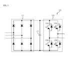
- the conventional series H-bridge medium voltage inverter thus described suffers from a disadvantage in that, because it is formed with a diode rectifier for an input terminal of a unit power cell, it is impossible to perform a regenerative operation to make it difficult to perform a fast acceleration or a fast deceleration. As a result, the conventional series H-bridge medium voltage inverter thus described has a disadvantage of taking a long time for decelerated operation during a decelerated operation. Another disadvantage is that each capacitance of DC-link capacitor of all unit power cells must be enlarged to increase the size of an entire system. Thus, there is a need to address the abovementioned disadvantages.
- the present disclosure is provided to solve the aforementioned disadvantages and it is an object of the present disclosure to provide a partial regenerative medium voltage inverter configured to combine a conventional series H-bridge medium voltage inverter with a regenerative unit power cell having an active rectifier capable of performing a regenerative operation. It should be emphasized, however, that the present disclosure is not limited to a particular disclosure, as explained above. It should be understood that other technical subjects not mentioned herein may be appreciated by those skilled in the art.
- a regenerative medium voltage inverter comprising: a plurality of power cells configured to transmit, by serially-connected three groups, a phase voltage to a motor; a plurality of input filters interconnected between an input power unit and the power cell to reduce harmonics of a 3-phase input power; and a plurality of switching signal generating units interconnected between an input power unit and the power cell to switch a voltage inputted to the power cell.
- the inverter further comprises a phase switching transformer electrically insulating the input power from the input power unit and providing the electrically insulated input power to each of the plurality of power cells.
- the input filter is mounted with three input terminals receiving the input power, and comprises inductors respectively connected to the input terminals, and capacitors connected with the inductors in a delta connection.
- first a second constituent element
- first constituent element a first constituent element without departing from the scope and spirit of the present disclosure
- first constituent element may be denoted as a second constituent element.
- FIG.3 is a structural view illustrating a regenerative medium voltage inverter according to an exemplary embodiment of the present disclosure, where a series H-bridge medium voltage inverter is exemplified.
- a regenerative medium voltage inverter (10) is an inverter that receives a voltage, whose rms (root mean square) value is over 600V in line-to-line voltage, from an input power unit (20) and supplies a 3-phase power to a motor (30).
- the motor (30) is an induction motor or a synchronous motor but is not limited thereto.
- FIG.4 is a detailed structural view illustrating an input filter of FIG.3 according to an exemplary embodiment of the present disclosure
- FIG.5 is a detailed structural view illustrating an input filter of FIG.3 according to another exemplary embodiment of the present disclosure.
- the input filter (12) includes inductors (51a ⁇ 51c) respectively connected in series to the 3-phase output of secondary winding side of the phase shift transformer (11) ⁇ To this end, the input filter (12) is formed with three input terminals ⁇ , capacitors (52a ⁇ 52c) connected to the inductors (51a ⁇ 51c) in delta connection, and damping resistors (53a ⁇ 53c) respectively connected in parallel to the inductors (51a ⁇ 51c).
- the damping resistors (53a ⁇ 53c) serve to remove resonance in the input voltage, if the resonance is generated in the input voltage.
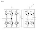
- the power cell (14) includes an active rectifying unit (61), a DC-link capacitor (62) and an inverter unit (63).
- An input of the active rectifying unit (61) is an output voltage of the input filter (12) of FIG. 3 , from which a DC rectified from the 3-phase voltage is outputted.
- the active rectifying unit (61) includes six transistor switches (hereinafter referred to as switch, 61a ⁇ 61f), where the transistor is preferably an IGBT (Insulated Gate Bipolar Transistor), as shown in FIG.6 .
- the DC-link capacitor (62) stores an input power of the active rectifying unit (61).
- the inverter unit (63) is preferably a single phase full bridge inverter to synthesize output voltages form a voltage of the DC link in response to control of a controller (not shown).
- the inverter unit (63) includes four switches (63a ⁇ 63d), and each switch is formed by connecting in parallel a transistor and a diode. Now, a circuit of FIG. 3 will be described in detail with an emphasis on a difference from that of FIG.1 .
- the input filter (12) of FIG.3 configured as in FIG.4 or FIG.5 receives an output of the phase shift transformer (11), and inductances of inductors (41a ⁇ 41c or 51a ⁇ 51c) at the input filter (12) are sufficiently greater in value than those of leakage inductance of the phase shift transformer (11).
- L filter > 2 ⁇ L leakage_ 2 ⁇ nd where, L filter is an inductance of inductors (41a ⁇ 41c or 51a ⁇ 51c) at the input filter (12), and L leakage_ 2 nd is a leakage inductance of the phase shift transformer (11) converted to a secondary winding side.
- capacitance of capacitors (42a ⁇ 42c or 52a ⁇ 52c) of FIG.4 or FIG.5 may be obtained from the following relations.
- C filter 1 2 ⁇ L filter ⁇ ⁇ c 2 where, ⁇ c is a cut-off frequency of input filter (12), and has a value six times greater than an input power frequency.
- An input line-to-line voltage measured by the input filter (12) determines the switching of the active rectifying unit of FIG.6 , where a measured position of the voltage is situated between the phase shift transformer (11) and the input filter (12).
- FIG.7 is a schematic view illustrating an input filter connected to a power cell in FIG.3 and a switching signal generating unit.
- the switching signal generating unit (13) serves to generate a switching signal of the active rectifying unit (61). That is, the switching signal generating unit (13) measures an input line-to-line voltage from the 3-phase voltage inputted from the input filter (12), extracts an input power angle from the measured line-to-line voltage and transmits a gating signal, i.e., a switching signal to six transistors (61a ⁇ 61f) of the active rectifying unit (61).
- a gating signal i.e., a switching signal to six transistors (61a ⁇ 61f) of the active rectifying unit (61).
- FIG.8 is a schematic view illustrating a switching signal generated by the switching signal generating unit of FIG.3 and a resultant switching of an active rectifying unit according to an exemplary embodiment of the present disclosure, where the switching signal generated by the switching signal generating unit of FIG.3 in response to an input line-to-line voltage is exemplified.
- 'V ab ' represents an ab line-to-line voltage
- 'V bc ' represents a bc line-to-line voltage
- 'V ca ' represents a ca line-to-line voltage
- the switching signal generating unit (13) transmits ON/OFF signals relative to switches (61a ⁇ 61f) of the active rectifying unit (61) to each switch (61a ⁇ 61f) of the transistors.
- the switching of the active rectifying unit has a same switching frequency as frequency of the input power.
- switches of 61d and 61e of FIG. 6 are turned on, in a case the input power angle is from ⁇ /3 to 2 ⁇ /3, switches of 61a and 61d are turned on, and in a case the input power angle is from 2 ⁇ /3 to ⁇ , switches of 61a and 61f are turned on.
- switches of 61c and 61f are turned on
- switches of 61b and 61c are turned on
- switches of 61b and 61e are turned on
- switches of 61b and 61e are turned on.
- the switching pattern is periodically repeated at every 2 ⁇ in response to changes in input power angle, by which the power cell (14) including the active rectifying unit (61) is enabled for bi-directional power transmission.
- FIG. 8 has illustrated the switching of the active rectifying unit (61) relative to the input line-to-line voltage, it should be apparent to the skilled in the art that an identical operation can be made by measuring an input phase voltage, which will be explained later.
- E a is an input 'a' phase voltage
- E b is an input 'b' phase voltage
- E c is an input 'c' phase voltage.
- the switching of FIG. 8 may be also applied to the phase voltage, because the phase voltage can be obtained from the line-to-line voltage.
- the active rectifying unit (61) is such that the switches (61a ⁇ 61f) are operated at a point same as that of diode of the diode rectifying unit (21) being operated, whereby the phase shift transformer (11) and the power cell (14) are electrically and instantaneously connected to enable a regenerative operation.
- phase shift transformer (11) and the power cell (14) are connected by the switching of FIG. 8 , the following relationship occurs.
- 'a' output voltage and current of a motor (30) may be defined by the following equations 14 and 15 respectively, and 'b' and 'c' output voltages and currents of the motor (30) may be also defined by the following equations 16, 17, 18 and 19 respectively.
- ⁇ is a load angle
- ⁇ is an operating frequency
- t time
- V o and I o are rms values of output voltage and output current.
- Equation 20 power generated from 'a' phase of motor (30) can be obtained from the following Equation 20, and likewise, powers generated from 'b' phase and 'c' phase can be obtained from Equations 21 and 22.
- the phase shift transformer (11) and the power cell (14) are instantaneously connected to allow a system to output a predetermined power, whereby a DC-link capacitor of unit power cell (14) can be reduces in size over that of the conventional medium voltage inverter.
- the unit power cell having the conventional diode rectifying unit as shown in FIGS.1 and 2 has a ripple twice the operating frequency in the power outputted by each unit power cell as shown in Equations 20, 21 and 22.
- the power cell (14) including the active rectifying unit (61) can advantageously reduce the size of the DC-link capacitor of each power cell (14), because an input terminal and an output terminal are instantaneously connected, a ripple power is not concentrated in the DC-link capacitor of each unit power cell, and a sum of 3-phase powers is available only in DC components as shown in Equation 23.
- the regenerative medium voltage inverter have an industrial applicability in that regenerative operation is enabled by changing structure of input terminal of a unit power cell at a series H-bridge medium voltage inverter, and a dynamic braking resistor is not required to reduce the size of a DC-link capacitor over that of a conventional medium voltage inverter.
Landscapes
- Engineering & Computer Science (AREA)
- Power Engineering (AREA)
- Inverter Devices (AREA)
- Control Of Ac Motors In General (AREA)
- Rectifiers (AREA)
Applications Claiming Priority (1)
| Application Number | Priority Date | Filing Date | Title |
|---|---|---|---|
| KR1020110104296A KR20130039612A (ko) | 2011-10-12 | 2011-10-12 | 회생형 고압 인버터 |
Publications (2)
| Publication Number | Publication Date |
|---|---|
| EP2582032A2 true EP2582032A2 (de) | 2013-04-17 |
| EP2582032A3 EP2582032A3 (de) | 2014-05-28 |
Family
ID=46940258
Family Applications (1)
| Application Number | Title | Priority Date | Filing Date |
|---|---|---|---|
| EP12181824.9A Withdrawn EP2582032A3 (de) | 2011-10-12 | 2012-08-27 | Mittelspannungsmultizellenumrichter aus kaskadierten H-Brücken mit bidirektionaler Einspeisung der Zellen |
Country Status (5)
| Country | Link |
|---|---|
| US (1) | US8922151B2 (de) |
| EP (1) | EP2582032A3 (de) |
| JP (1) | JP2013085453A (de) |
| KR (1) | KR20130039612A (de) |
| CN (1) | CN103051283B (de) |
Cited By (3)
| Publication number | Priority date | Publication date | Assignee | Title |
|---|---|---|---|---|
| EP3045343A1 (de) * | 2015-01-16 | 2016-07-20 | ALSTOM Transport Technologies | Wandler für eine elektrische zuleitung und/oder substation zur rückgewinnung der bremsenergie |
| US9455651B2 (en) | 2014-12-16 | 2016-09-27 | Caterpillar Inc. | Motor driver having integrated braking chopper |
| WO2022216279A1 (en) * | 2021-04-07 | 2022-10-13 | Siemens Aktiengesellschaft | Regenerative multicell drive system with overlap angle in fundamental frequency modulation |
Families Citing this family (11)
| Publication number | Priority date | Publication date | Assignee | Title |
|---|---|---|---|---|
| FR2982092B1 (fr) * | 2011-11-02 | 2015-01-02 | Valeo Systemes De Controle Moteur | Module de puissance et dispositif electrique pour l'alimentation et la charge combinees respectivement d'un accumulateur et d'un moteur |
| US9722503B2 (en) * | 2013-03-28 | 2017-08-01 | Teco-Westinghouse Motor Company | Modular configurable multi-megawatt power amplifier |
| US9654021B2 (en) * | 2013-10-09 | 2017-05-16 | Rockwell Automation Technologies, Inc. | Multifunction power converter with option for integrated magnetics |
| US10629396B2 (en) | 2017-05-08 | 2020-04-21 | Rockwell Automation Technologies, Inc. | Arc flash resistant enclosure with segregated cooling |
| US10011178B1 (en) * | 2017-06-08 | 2018-07-03 | Ford Global Technologies, Llc | DC inverter having reduced switching loss and reduced voltage spikes |
| US11038436B2 (en) * | 2017-09-25 | 2021-06-15 | Lsis Co., Ltd. | Inverter system |
| US11876438B2 (en) * | 2019-01-04 | 2024-01-16 | Innomotics Gmbh | Reducing input harmonic distortion in a power supply |
| US10924025B2 (en) | 2019-04-24 | 2021-02-16 | Rockwell Automation Technologies, Inc. | Regenerative cascaded H bridge power supply |
| US10651760B1 (en) * | 2019-04-24 | 2020-05-12 | Rockwell Automation Technologies, Inc | Reduced semiconductor device power cell voltage drive |
| DE102020104252A1 (de) * | 2019-05-21 | 2020-11-26 | Vacon Oy | Leistungswandler |
| JP7514778B2 (ja) * | 2021-02-05 | 2024-07-11 | 株式会社豊田中央研究所 | 電源システム |
Family Cites Families (17)
| Publication number | Priority date | Publication date | Assignee | Title |
|---|---|---|---|---|
| US4445167A (en) * | 1981-10-05 | 1984-04-24 | Tokyo Shibaura Denki Kabushiki Kaisha | Inverter system |
| FR2610153B1 (fr) * | 1987-01-28 | 1989-04-07 | Merlin Gerin | Filtre dissipatif passe-bas |
| US5625545A (en) * | 1994-03-01 | 1997-04-29 | Halmar Robicon Group | Medium voltage PWM drive and method |
| US6014323A (en) * | 1997-08-08 | 2000-01-11 | Robicon Corporation | Multiphase power converter |
| US5990654A (en) * | 1998-01-21 | 1999-11-23 | Allen-Bradley Company, Llc | Apparatus for eliminating motor voltage reflections and reducing EMI currents |
| JP2000268756A (ja) * | 1999-03-12 | 2000-09-29 | Toshiba Corp | 荷電ビーム装置および荷電ビームの制御方法 |
| US6847531B2 (en) * | 2001-01-02 | 2005-01-25 | General Electric Company | System and method for regenerative PWM AC power conversion |
| US7088073B2 (en) * | 2003-01-24 | 2006-08-08 | Toshiba Internationl Corporation | Inverter drive system |
| JP2005348573A (ja) | 2004-06-07 | 2005-12-15 | Toshiba Mitsubishi-Electric Industrial System Corp | 電力変換装置 |
| DE102005005688A1 (de) * | 2005-02-08 | 2006-08-10 | Siemens Ag | Filter für einen rückspeisefähigen Stromrichter mit Grundfrequenztaktung |
| JP4609102B2 (ja) | 2005-02-15 | 2011-01-12 | 株式会社明電舎 | 直列多重インバータ装置 |
| US7508147B2 (en) | 2005-05-19 | 2009-03-24 | Siemens Energy & Automation, Inc. | Variable-frequency drive with regeneration capability |
| RU2007149319A (ru) * | 2005-05-27 | 2009-07-10 | Сименс Энерджи Энд Отомейшн, Инк. (Us) | Функционирование инверторов с перемодуляцией |
| BRPI0616123B1 (pt) | 2005-09-09 | 2018-05-29 | Siemens Aktiengesellschaft | Método de controlar um sistema de distribuição de energia, método de operar um sistema de distribuição de energia e sistema de distribuição de energia |
| JP4849310B2 (ja) | 2005-10-28 | 2012-01-11 | 富士電機株式会社 | 交流交流電力変換器の制御装置 |
| JP2009106081A (ja) | 2007-10-23 | 2009-05-14 | Mitsubishi Heavy Ind Ltd | 電力変換器 |
| JP5230207B2 (ja) | 2008-01-07 | 2013-07-10 | 三菱重工業株式会社 | 双方向電力変換器およびその制御方法 |
-
2011
- 2011-10-12 KR KR1020110104296A patent/KR20130039612A/ko not_active Ceased
-
2012
- 2012-08-27 EP EP12181824.9A patent/EP2582032A3/de not_active Withdrawn
- 2012-09-14 US US13/615,608 patent/US8922151B2/en active Active
- 2012-09-19 JP JP2012206014A patent/JP2013085453A/ja active Pending
- 2012-10-12 CN CN201210387267.1A patent/CN103051283B/zh not_active Expired - Fee Related
Non-Patent Citations (1)
| Title |
|---|
| "Leistungselektronische Schaltungen: Funktion, Auslegung und Anwendung", 26 October 2012, SPRINGER-VERLAG, ISBN: 978-3-642-30104-9, article DIRK SCHRÖDER: "Leistungselektronische Schaltungen: Funktion, Auslegung und Anwendung", pages: 604 - 607, XP055466935 * |
Cited By (7)
| Publication number | Priority date | Publication date | Assignee | Title |
|---|---|---|---|---|
| US9455651B2 (en) | 2014-12-16 | 2016-09-27 | Caterpillar Inc. | Motor driver having integrated braking chopper |
| EP3045343A1 (de) * | 2015-01-16 | 2016-07-20 | ALSTOM Transport Technologies | Wandler für eine elektrische zuleitung und/oder substation zur rückgewinnung der bremsenergie |
| FR3031849A1 (fr) * | 2015-01-16 | 2016-07-22 | Alstom Transp Tech | Convertisseur d'alimentation reseau et/ou de sous-station de recuperation de l'energie de freinage |
| US10554117B2 (en) | 2015-01-16 | 2020-02-04 | Alstom Transport Technologies | Convertor for electric feeder and/or substation for recuperating the braking energy |
| WO2022216279A1 (en) * | 2021-04-07 | 2022-10-13 | Siemens Aktiengesellschaft | Regenerative multicell drive system with overlap angle in fundamental frequency modulation |
| AU2021439254B2 (en) * | 2021-04-07 | 2024-09-19 | Innomotics Gmbh | Regenerative multicell drive system with overlap angle in fundamental frequency modulation |
| US12539764B2 (en) | 2021-04-07 | 2026-02-03 | Innomotics Gmbh | Regenerative multicell drive system with overlap angle in fundamental frequency modulation |
Also Published As
| Publication number | Publication date |
|---|---|
| CN103051283B (zh) | 2016-02-17 |
| KR20130039612A (ko) | 2013-04-22 |
| JP2013085453A (ja) | 2013-05-09 |
| US20130093376A1 (en) | 2013-04-18 |
| EP2582032A3 (de) | 2014-05-28 |
| CN103051283A (zh) | 2013-04-17 |
| US8922151B2 (en) | 2014-12-30 |
Similar Documents
| Publication | Publication Date | Title |
|---|---|---|
| EP2582032A2 (de) | Mittelspannungsmultizellenumrichter aus kaskadierten H-Brücken mit bidirektionaler Einspeisung der Zellen | |
| US20190363644A1 (en) | Internal paralleled active neutral point clamped converter with logic-based flying capacitor voltage balancing | |
| US9337746B2 (en) | Multilevel inverter | |
| US9331595B2 (en) | Multi-level inverter | |
| EP3089338A1 (de) | Kaskadierter mehrpunktumrichter mit t-typ 3-punkt vollbrückenzellen und zellinterner bypass funktion | |
| CN103503268B (zh) | 风能变流器 | |
| US9054600B2 (en) | Control apparatus for regenerative medium voltage inverter | |
| CA2565707C (en) | Low harmonics, polyphase converter circuit | |
| EP3068029A1 (de) | Umrichtersystem | |
| JP2014018015A (ja) | 電圧型電力変換装置の制御装置及び制御方法 | |
| JP2016537954A (ja) | 直流中間回路の中間点と交流グリッドの中性導体の端子間のスイッチを含むインバータとインバータを動作させる方法 | |
| US11949348B2 (en) | Bi-directional line-interphase transformer-based converter | |
| JP2011130517A (ja) | 電力変換装置 | |
| US20150008856A1 (en) | Multi-level medium-voltage inverter | |
| JP2015006077A (ja) | 蓄電装置を搭載した電力変換装置 | |
| CN104734528B (zh) | 多相电力驱动器及其功率单元 | |
| US20080247211A1 (en) | Active generator control sequence | |
| RU2600125C2 (ru) | Преобразователь и способ его эксплуатации для преобразования напряжений | |
| JP3899850B2 (ja) | 電源装置 | |
| US20050078497A1 (en) | Three phase isolated vector switching AC to AC frequency converters | |
| Jin et al. | Control and modulation of the stacked polyphase bridges inverter | |
| Dutta | Some aspects on 3-phase bridge inverter (180 degree mode) | |
| CN101860233B (zh) | 用于运行变频器电路的方法及用于执行该方法的装置 | |
| KR20130039610A (ko) | 부분 회생형 고압 인버터 | |
| EP4633021A1 (de) | Elektrisches energiesystem |
Legal Events
| Date | Code | Title | Description |
|---|---|---|---|
| PUAI | Public reference made under article 153(3) epc to a published international application that has entered the european phase |
Free format text: ORIGINAL CODE: 0009012 |
|
| AK | Designated contracting states |
Kind code of ref document: A2 Designated state(s): AL AT BE BG CH CY CZ DE DK EE ES FI FR GB GR HR HU IE IS IT LI LT LU LV MC MK MT NL NO PL PT RO RS SE SI SK SM TR |
|
| AX | Request for extension of the european patent |
Extension state: BA ME |
|
| PUAL | Search report despatched |
Free format text: ORIGINAL CODE: 0009013 |
|
| AK | Designated contracting states |
Kind code of ref document: A3 Designated state(s): AL AT BE BG CH CY CZ DE DK EE ES FI FR GB GR HR HU IE IS IT LI LT LU LV MC MK MT NL NO PL PT RO RS SE SI SK SM TR |
|
| AX | Request for extension of the european patent |
Extension state: BA ME |
|
| RIC1 | Information provided on ipc code assigned before grant |
Ipc: H02M 1/12 20060101ALI20140422BHEP Ipc: H02M 7/49 20070101AFI20140422BHEP Ipc: H02M 5/458 20060101ALI20140422BHEP |
|
| 17P | Request for examination filed |
Effective date: 20141128 |
|
| RBV | Designated contracting states (corrected) |
Designated state(s): AL AT BE BG CH CY CZ DE DK EE ES FI FR GB GR HR HU IE IS IT LI LT LU LV MC MK MT NL NO PL PT RO RS SE SI SK SM TR |
|
| 17Q | First examination report despatched |
Effective date: 20161017 |
|
| STAA | Information on the status of an ep patent application or granted ep patent |
Free format text: STATUS: THE APPLICATION IS DEEMED TO BE WITHDRAWN |
|
| 18D | Application deemed to be withdrawn |
Effective date: 20190528 |