US8922151B2 - Regenerative medium voltage inverter - Google Patents
Regenerative medium voltage inverter Download PDFInfo
- Publication number
- US8922151B2 US8922151B2 US13/615,608 US201213615608A US8922151B2 US 8922151 B2 US8922151 B2 US 8922151B2 US 201213615608 A US201213615608 A US 201213615608A US 8922151 B2 US8922151 B2 US 8922151B2
- Authority
- US
- United States
- Prior art keywords
- input
- voltage
- power
- inverter
- unit
- Prior art date
- Legal status (The legal status is an assumption and is not a legal conclusion. Google has not performed a legal analysis and makes no representation as to the accuracy of the status listed.)
- Active, expires
Links
- 230000001172 regenerating effect Effects 0.000 title claims abstract description 23
- 239000003990 capacitor Substances 0.000 claims abstract description 23
- 239000000284 extract Substances 0.000 claims description 3
- 230000010363 phase shift Effects 0.000 description 11
- 238000013016 damping Methods 0.000 description 5
- 230000008901 benefit Effects 0.000 description 4
- 239000000470 constituent Substances 0.000 description 4
- 230000004048 modification Effects 0.000 description 4
- 238000012986 modification Methods 0.000 description 4
- 230000004044 response Effects 0.000 description 3
- 238000004804 winding Methods 0.000 description 3
- 230000001133 acceleration Effects 0.000 description 2
- 230000006698 induction Effects 0.000 description 2
- 230000001360 synchronised effect Effects 0.000 description 2
- 230000004075 alteration Effects 0.000 description 1
- 230000005540 biological transmission Effects 0.000 description 1
- 230000000694 effects Effects 0.000 description 1
- 238000010292 electrical insulation Methods 0.000 description 1
- 238000002955 isolation Methods 0.000 description 1
- 238000000034 method Methods 0.000 description 1
- 230000008569 process Effects 0.000 description 1
- 230000002194 synthesizing effect Effects 0.000 description 1
Images



Classifications
-
- H—ELECTRICITY
- H02—GENERATION; CONVERSION OR DISTRIBUTION OF ELECTRIC POWER
- H02M—APPARATUS FOR CONVERSION BETWEEN AC AND AC, BETWEEN AC AND DC, OR BETWEEN DC AND DC, AND FOR USE WITH MAINS OR SIMILAR POWER SUPPLY SYSTEMS; CONVERSION OF DC OR AC INPUT POWER INTO SURGE OUTPUT POWER; CONTROL OR REGULATION THEREOF
- H02M7/00—Conversion of AC power input into DC power output; Conversion of DC power input into AC power output
- H02M7/42—Conversion of DC power input into AC power output without possibility of reversal
- H02M7/44—Conversion of DC power input into AC power output without possibility of reversal by static converters
- H02M7/48—Conversion of DC power input into AC power output without possibility of reversal by static converters using discharge tubes with control electrode or semiconductor devices with control electrode
- H02M7/483—Converters with outputs that each can have more than two voltages levels
- H02M7/49—Combination of the output voltage waveforms of a plurality of converters
-
- H—ELECTRICITY
- H02—GENERATION; CONVERSION OR DISTRIBUTION OF ELECTRIC POWER
- H02M—APPARATUS FOR CONVERSION BETWEEN AC AND AC, BETWEEN AC AND DC, OR BETWEEN DC AND DC, AND FOR USE WITH MAINS OR SIMILAR POWER SUPPLY SYSTEMS; CONVERSION OF DC OR AC INPUT POWER INTO SURGE OUTPUT POWER; CONTROL OR REGULATION THEREOF
- H02M1/00—Details of apparatus for conversion
- H02M1/12—Arrangements for reducing harmonics from AC input or output
- H02M1/126—Arrangements for reducing harmonics from AC input or output using passive filters
-
- H—ELECTRICITY
- H02—GENERATION; CONVERSION OR DISTRIBUTION OF ELECTRIC POWER
- H02M—APPARATUS FOR CONVERSION BETWEEN AC AND AC, BETWEEN AC AND DC, OR BETWEEN DC AND DC, AND FOR USE WITH MAINS OR SIMILAR POWER SUPPLY SYSTEMS; CONVERSION OF DC OR AC INPUT POWER INTO SURGE OUTPUT POWER; CONTROL OR REGULATION THEREOF
- H02M5/00—Conversion of AC power input into AC power output, e.g. for change of voltage, for change of frequency, for change of number of phases
- H02M5/40—Conversion of AC power input into AC power output, e.g. for change of voltage, for change of frequency, for change of number of phases with intermediate conversion into DC
- H02M5/42—Conversion of AC power input into AC power output, e.g. for change of voltage, for change of frequency, for change of number of phases with intermediate conversion into DC by static converters
- H02M5/44—Conversion of AC power input into AC power output, e.g. for change of voltage, for change of frequency, for change of number of phases with intermediate conversion into DC by static converters using discharge tubes or semiconductor devices to convert the intermediate DC into AC
- H02M5/453—Conversion of AC power input into AC power output, e.g. for change of voltage, for change of frequency, for change of number of phases with intermediate conversion into DC by static converters using discharge tubes or semiconductor devices to convert the intermediate DC into AC using devices of a triode or transistor type requiring continuous application of a control signal
- H02M5/458—Conversion of AC power input into AC power output, e.g. for change of voltage, for change of frequency, for change of number of phases with intermediate conversion into DC by static converters using discharge tubes or semiconductor devices to convert the intermediate DC into AC using devices of a triode or transistor type requiring continuous application of a control signal using semiconductor devices only
- H02M5/4585—Conversion of AC power input into AC power output, e.g. for change of voltage, for change of frequency, for change of number of phases with intermediate conversion into DC by static converters using discharge tubes or semiconductor devices to convert the intermediate DC into AC using devices of a triode or transistor type requiring continuous application of a control signal using semiconductor devices only having a rectifier with controlled elements
Definitions
- the present disclosure relates to a regenerative medium voltage inverter.
- inverter In general, equipment referred to as a power converter, inverter or drive is employed to provide power to another piece of equipment such as a motor.
- inverter inverter is used generally herein to refer to inverters, converters, drives
- a utility connection to receive incoming input power such as a three-phase AC (Alternating Current) power.
- a medium voltage inverter is an inverter having an input power whose rms (root mean square) value is over 600V for a line-to-line voltage, and is generally used to drive an industrial load of large inertia of, for a non-limiting, fans, pumps and compressors.
- variable speed operations frequently occur, where regenerative operations are generated, if a fast acceleration or a fast deceleration is required.
- FIG. 1 is a configurative view of a series H-bridge medium voltage inverter according to prior art, where the inverter is configured with a three-step unit power cells.
- a conventional medium voltage inverter ( 100 ) receives a 3-phase power from an input power unit ( 200 ) and supplies the power to a motor ( 300 ).
- the input power unit ( 200 ) provides a 3-phase whose rms (root mean square) value is over 600V for a line-to-line voltage.
- the motor ( 300 ) is a 3-phase high voltage motor, and may be an induction machine or a synchronous machine.
- a phase switching transformer ( 110 ) provides a galvanic isolation between the input power unit ( 200 ) and the medium voltage inverter ( 100 ), reduces harmonics at an input terminal and provides an input 3-phase power adequate to each unit power cell ( 120 ).
- the unit power cell ( 120 ) receives the power from the phase switching transformer ( 110 ) and outputs a phase voltage to the motor ( 300 ), where each unit power cell ( 120 ) is composed of a group.
- the power cells A 1 , A 2 and A 3 are connected in series at an output voltage to synthesize ‘a’ phase voltage of the motor ( 300 ), the power cells B 1 , B 2 and B 3 are connected in series at an output voltage to synthesize ‘b’ phase voltage of the motor ( 300 ), and the power cells C 1 , C 2 and C 3 are connected in series at an output voltage to synthesize ‘c’ phase voltage of the motor ( 300 ).
- the synthesized ‘b’ phase voltage and ‘a’ phase voltage are apart with a 120 degree phase difference, and the synthesized ‘c’ phase voltage and ‘b’ phase voltage are also apart with a 120 degree phase difference.
- FIG. 2 is a configurative view illustrating a unit power cell of FIG. 1 .
- the unit power cell ( 120 ) includes a 3-phase diode rectifier ( 121 ), a DC-link capacitor ( 122 ) and an inverter ( 123 ).
- the 3-phase diode rectifier ( 121 ) outputs a 3-phase rectified DC voltage using an output voltage of the phase switching transformer ( 110 ) as an input.
- the DC-link capacitor ( 122 ) stores the input power of the 3-phase diode rectifier ( 121 ).
- the inverter ( 123 ) is a single phase full bridge inverter to synthesize output voltages via switching of the switching elements ( 123 a ⁇ 123 d ) using the voltages received from the DC-link capacitor ( 122 ).
- the phase switching transformer ( 110 ) converts a phase and size of a high voltage input power catering to requirement of the unit power cell ( 120 ).
- An output voltage of the phase switching transformer ( 110 ) becomes of an input power of each unit power cell ( 120 ) and is converted to a DC through the 3-phase diode rectifier ( 121 ) of FIG. 2 .
- the DC-link capacitor ( 122 ) serves to constantly maintain the output voltage of the 3-phase diode rectifier ( 121 ).
- the single phase full bridge inverter ( 123 ) synthesizes the AC output voltages with the voltages from the DC-link capacitor ( 122 ). IF the voltage of the DC-link capacitor ( 122 ) is assumed as ‘E’, an output voltage of the inverter ( 123 ) would be shown as ‘E’, ‘O’ and ‘ ⁇ E’ according to switching state.
- the synthesized output voltage is ‘E’
- the synthesized output voltage is ‘ ⁇ E’
- the synthesized output voltage is ‘0’
- output voltages of A 1 , A 2 , A 3 , B 1 , B 2 , B 3 and C 1 , C 2 , C 3 are all serially connected, such that serially connected output phase voltages are synthesized in 7 steps of ‘3E’, ‘2E’, ‘E’, ‘0’, ‘ ⁇ E’, ‘ ⁇ 2E, and ‘ ⁇ 3E’.
- An output line-to-line voltage of the motor from the synthesized output phase voltages may be synthesized in 13 steps of ‘6E’, ‘5E’, ‘4E’, ‘3E’, ‘2E’, ‘E’, ‘0’, ‘ ⁇ E’, ‘ ⁇ 2E’, ‘ ⁇ 3E’, ‘ ⁇ 4E’, ‘ ⁇ 5E’, ‘ ⁇ 6E’, which may be generalized as below.
- m 2 H+ 1 [Equation 1]
- each unit power cell ( 120 ) being an output of a single full bridge inverter
- an output of a DC-link power is formed with a voltage ripple.
- an output voltage and an output current of each cell are defined as under.
- v O ⁇ square root over (2) ⁇ V O sin ⁇ t [Equation 3]
- i o ⁇ square root over (2) ⁇ I o sin( ⁇ t ⁇ ) [Equation 4]
- ⁇ is a load angle
- ⁇ is an operating frequency
- t time
- V O and I o are an output voltage and an rms value of an output current.
- An output power of unit power cell ( 120 ) can be obtained as below based on the Equations 3 and 4.
- the conventional series H-bridge medium voltage inverter thus described suffers from a disadvantage in that, because it is formed with a diode rectifier for an input terminal of a unit power cell, it is impossible to perform a regenerative operation to make it difficult to perform a fast acceleration or a fast deceleration.
- the conventional series H-bridge medium voltage inverter thus described has a disadvantage of taking a long time for decelerated operation during a decelerated operation.
- Another disadvantage is that each capacitance of DC-link capacitor of all unit power cells must be enlarged to increase the size of an entire system.
- the present disclosure is provided to solve the aforementioned disadvantages and it is an object of the present disclosure to provide a partial regenerative medium voltage inverter configured to combine a conventional series H-bridge medium voltage inverter with a regenerative unit power cell having an active rectifier capable of performing a regenerative operation.
- a regenerative medium voltage inverter comprising: a plurality of power cells configured to transmit, by serially-connected three groups, a phase voltage to a motor; a plurality of input filters interconnected between an input power unit and the power cell to reduce harmonics of a 3-phase input power; and a plurality of switching signal generating units interconnected between an input power unit and the power cell to switch a voltage inputted to the power cell.
- the inverter further comprises a phase switching transformer electrically insulating the input power from the input power unit and providing the electrically insulated input power to each of the plurality of power cells.
- the input filter is mounted with three input terminals receiving the input power, and comprises inductors respectively connected to the input terminals, and capacitors connected with the inductors in a delta connection.
- the input filter further comprises resistors connected in parallel to each of the inductors to remove resonance of the input power.
- the power cell comprises an active rectifying unit receiving an output voltage of the input filter to output a DC (direct current) voltage rectified from the output voltage, a DC-link capacitor storing the DC voltage, and an inverter unit synthesizing output voltage from the stores DC voltage.
- an active rectifying unit receiving an output voltage of the input filter to output a DC (direct current) voltage rectified from the output voltage, a DC-link capacitor storing the DC voltage, and an inverter unit synthesizing output voltage from the stores DC voltage.
- the active rectifying unit comprises a plurality of switches connected in parallel to each phase voltage.
- the switching signal generating unit controls the plurality of switches to sequentially connect the power cell and the input power unit.
- each of the switches comprises a transistor and a diode that are connected in parallel.
- the switching signal generating unit measures a line-to-line voltage using the input power from the input power unit, extracts a power angle using the measured line-to-line voltage and switches the voltage inputted to the power cell.
- the regenerative medium voltage inverter has an advantageous effect in that regenerative operation is enabled by changing structure of input terminal of a unit power cell at a series H-bridge medium voltage inverter, and a dynamic braking resistor is not required to reduce the size of a DC-link capacitor over that of a conventional medium voltage inverter.
- FIG. 1 is a structural view illustrating a series H-bridge medium voltage inverter according to prior art
- FIG. 2 is a structural view illustrating a unit power cell of FIG. 1 ;
- FIG. 3 is a structural view illustrating a regenerative medium voltage inverter according to an exemplary embodiment of the present disclosure
- FIG. 4 is a detailed structural view illustrating an input filter of FIG. 3 according to an exemplary embodiment of the present disclosure
- FIG. 5 is a detailed structural view illustrating an input filter of FIG. 3 according to another exemplary embodiment of the present disclosure
- FIG. 6 is a detailed structural view illustrating a power cell of FIG. 3 according to an exemplary embodiment of the present disclosure
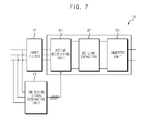
- FIG. 7 is a schematic view illustrating an input filter connected to a power cell in FIG. 3 and a switching signal generating unit;
- FIG. 8 is a schematic view illustrating a switching signal generated by the switching signal generating unit of FIG. 3 and a resultant switching of an active rectifying unit according to an exemplary embodiment of the present disclosure.
- FIGS. 1-8 of the drawings like numerals being used for like and corresponding parts of the various drawings.
- Other features and advantages of the disclosed embodiments will be or will become apparent to one of ordinary skill in the art upon examination of the following figures and detailed description. It is intended that all such additional features and advantages be included within the scope of the disclosed embodiments, and protected by the accompanying drawings.
- the illustrated figures are only exemplary and not intended to assert or imply any limitation with regard to the environment, architecture, or process in which different embodiments may be implemented. Accordingly, the described aspect is intended to embrace all such alterations, modifications, and variations that fall within the scope and novel idea of the present invention.
- first a second constituent element
- first constituent element a first constituent element without departing from the scope and spirit of the present disclosure
- first constituent element may be denoted as a second constituent element.
- FIG. 3 is a structural view illustrating a regenerative medium voltage inverter according to an exemplary embodiment of the present disclosure, where a series H-bridge medium voltage inverter is exemplified.
- a regenerative medium voltage inverter ( 10 ) is an inverter that receives a voltage, whose rms (root mean square) value is over 600V in line-to-line voltage, from an input power unit ( 20 ) and supplies a 3-phase power to a motor ( 30 ).
- the motor ( 30 ) is an induction motor or a synchronous motor but is not limited thereto.
- the regenerative medium voltage inverter ( 10 ) includes a phase shift transformer ( 11 ), a plurality of input filters ( 12 ), a plurality of switching signal generating units ( 13 ) and a plurality of power cells ( 14 ).
- FIG. 3 exemplifies a 3-level unit power cell, such that the number of power cells ( 14 ) providing the 3-phase voltage to the motor ( 30 ) totals 9, and the number of input filters ( 12 ) and the switching signal generating units ( 13 ), being respectively connected to the power cells ( 14 ), totals 9 respectively in the present disclosure.
- those numbers may be changed according to the number of power cells ( 14 ).
- switching signal generating unit ( 13 ) Although only one switching signal generating unit ( 13 ) is illustrated as transmitting signal to A 1 in FIG. 3 for convenience sake, it is not limited thereto and it should be apparent that the switching signal generating unit ( 13 ) is mounted to each of the power cells.
- the phase shift transformer ( 11 ) serves to provide an electrical insulation between the input power unit ( 20 ) and the regenerative medium voltage inverter ( 10 ), to reduce harmonics from the input power and to provide a 3-phase power to each power cell ( 14 ).
- the input filter ( 12 ) functions to reduce harmonics from the input power.
- FIG. 4 is a detailed structural view illustrating an input filter of FIG. 3 according to an exemplary embodiment of the present disclosure
- FIG. 5 is a detailed structural view illustrating an input filter of FIG. 3 according to another exemplary embodiment of the present disclosure.
- the input filter ( 12 ) includes inductors ( 41 a ⁇ 41 c ) respectively connected in series to the 3-phase output of secondary winding side of the phase shift transformer ( 11 ) ⁇ To this end, the input filter ( 12 ) is formed with three input terminals ⁇ , and capacitors ( 42 a ⁇ 42 c ) connected to the inductors ( 41 a ⁇ 41 c ) in a delta connection.
- the input filter ( 12 ) includes inductors ( 51 a ⁇ 51 c ) respectively connected in series to the 3-phase output of secondary winding side of the phase shift transformer ( 11 ) ⁇ To this end, the input filter ( 12 ) is formed with three input terminals ⁇ , capacitors ( 52 a ⁇ 52 c ) connected to the inductors ( 51 a ⁇ 51 c ) in delta connection, and damping resistors ( 53 a ⁇ 53 c ) respectively connected in parallel to the inductors ( 51 a ⁇ 51 c ).
- the damping resistors ( 53 a ⁇ 53 c ) serve to remove resonance in the input voltage, if the resonance is generated in the input voltage.
- the unit power cell ( 14 ) functions to output a phase voltage of the motor ( 30 ), and each unit power cell ( 14 ) is formed with three groups that are connected in series.
- a 1 , A 2 and A 3 are serially connected at output voltages to synthesize ‘a’ phase voltage of the motor ( 30 )
- B 1 , B 2 and B 3 are serially connected at output voltages to synthesize ‘b’ phase voltage of the motor ( 30 )
- C 1 , C 2 and C 3 are serially connected at output voltages to synthesize ‘c’ phase voltage of the motor ( 30 ).
- the synthesized ‘b’ phase and ‘a’ phase voltages have a 120° phase difference
- the synthesized ‘c’ phase and ‘b’ phase voltages also have a 120° phase difference.
- FIG. 6 is a detailed structural view illustrating a power cell of FIG. 3 according to an exemplary embodiment of the present disclosure, where each of the plurality of power cells ( 14 ) has the same structure.
- the power cell ( 14 ) includes an active rectifying unit ( 61 ), a DC-link capacitor ( 62 ) and an inverter unit ( 63 ).
- An input of the active rectifying unit ( 61 ) is an output voltage of the input filter ( 12 ) of FIG. 3 , from which a DC rectified from the 3-phase voltage is outputted.
- the active rectifying unit ( 61 ) includes six transistor switches (hereinafter referred to as switch, 61 a ⁇ 61 f ), where the transistor is preferably an IGBT (Insulated Gate Bipolar Transistor), as shown in FIG. 6 .
- the DC-link capacitor ( 62 ) stores an input power of the active rectifying unit ( 61 ).
- the inverter unit ( 63 ) is preferably a single phase full bridge inverter to synthesize output voltages form a voltage of the DC link in response to control of a controller (not shown).
- the inverter unit ( 63 ) includes four switches ( 63 a ⁇ 63 d ), and each switch is formed by connecting in parallel a transistor and a diode. Now, a circuit of FIG. 3 will be described in detail with an emphasis on a difference from that of FIG. 1 .
- the input filter ( 12 ) of FIG. 3 configured as in FIG. 4 or FIG. 5 receives an output of the phase shift transformer ( 11 ), and inductances of inductors ( 41 a ⁇ 41 c or 51 a ⁇ 51 c ) at the input filter ( 12 ) are sufficiently greater in value than those of leakage inductance of the phase shift transformer ( 11 ).
- L filter >2 L leakage — 2nd [Equation 7] where, L filter is an inductance of inductors ( 41 a ⁇ 41 c or 51 a ⁇ 51 c ) at the input filter ( 12 ), and L leakage — 2nd is a leakage inductance of the phase shift transformer ( 11 ) converted to a secondary winding side.
- capacitance of capacitors ( 42 a ⁇ 42 c or 52 a ⁇ 52 c ) of FIG. 4 or FIG. 5 may be obtained from the following relations.
- ⁇ c 12 ⁇ ⁇ source ⁇ ( rad s ) [ Equation ⁇ ⁇ 9 ] where, ⁇ source is an input power frequency.
- An input line-to-line voltage measured by the input filter ( 12 ) determines the switching of the active rectifying unit of FIG. 6 , where a measured position of the voltage is situated between the phase shift transformer ( 11 ) and the input filter ( 12 ).
- FIG. 7 is a schematic view illustrating an input filter connected to a power cell in FIG. 3 and a switching signal generating unit.
- the switching signal generating unit ( 13 ) serves to generate a switching signal of the active rectifying unit ( 61 ). That is, the switching signal generating unit ( 13 ) measures an input line-to-line voltage from the 3-phase voltage inputted from the input filter ( 12 ), extracts an input power angle from the measured line-to-line voltage and transmits a gating signal, i.e., a switching signal to six transistors ( 61 a ⁇ 61 f ) of the active rectifying unit ( 61 ).
- FIG. 8 is a schematic view illustrating a switching signal generated by the switching signal generating unit of FIG. 3 and a resultant switching of an active rectifying unit according to an exemplary embodiment of the present disclosure, where the switching signal generated by the switching signal generating unit of FIG. 3 in response to an input line-to-line voltage is exemplified.
- ‘V ab ’ represents an ab line-to-line voltage
- ‘V bc ’ represents a be line-to-line voltage
- ‘V ca ’ represents a ca line-to-line voltage
- the switching signal generating unit ( 13 ) transmits ON/OFF signals relative to switches ( 61 a ⁇ 61 f ) of the active rectifying unit ( 61 ) to each switch ( 61 a ⁇ 61 f ) of the transistors.
- the switching of the active rectifying unit has a same switching frequency as frequency of the input power.
- switches of 61 c and 61 f are turned on
- switches of 61 b and 61 c are turned on
- switches of 61 b and 61 c are turned on
- switches of 61 b and 61 e are turned on.
- the switching pattern is periodically repeated at every 2 ⁇ in response to changes in input power angle, by which the power cell ( 14 ) including the active rectifying unit ( 61 ) is enabled for bi-directional power transmission.
- FIG. 8 has illustrated the switching of the active rectifying unit ( 61 ) relative to the input line-to-line voltage, it should be apparent to the skilled in the art that an identical operation can be made by measuring an input phase voltage, which will be explained later.
- E a V ab - V ca 3 [ Equation ⁇ ⁇ 11 ]
- E b V bc - V ab 3 [ Equation ⁇ ⁇ 12 ]
- E c V ca - V bc 3 [ Equation ⁇ ⁇ 13 ]
- E a is an input ‘a’ phase voltage
- E b is an input ‘b’ phase voltage
- E c is an input ‘c’ phase voltage.
- the switching of FIG. 8 may be also applied to the phase voltage, because the phase voltage can be obtained from the line-to-line voltage.
- the active rectifying unit ( 61 ) is such that the switches ( 61 a ⁇ 61 f ) are operated at a point same as that of diode of the diode rectifying unit ( 21 ) being operated, whereby the phase shift transformer ( 11 ) and the power cell ( 14 ) are electrically and instantaneously connected to enable a regenerative operation.
- phase shift transformer ( 11 ) and the power cell ( 14 ) are connected by the switching of FIG. 8 , the following relationship occurs.
- ‘a’ output voltage and current of a motor ( 30 ) may be defined by the following equations 14 and 15 respectively, and ‘b’ and ‘c’ output voltages and currents of the motor ( 30 ) may be also defined by the following equations 16, 17, 18 and 19 respectively.
- Equation 14 power generated from ‘a’ phase of motor ( 30 ) can be obtained from the following Equation 20, and likewise, powers generated from ‘b’ phase and ‘c’ phase can be obtained from Equations 21 and 22.
- the phase shift transformer ( 11 ) and the power cell ( 14 ) are instantaneously connected to allow a system to output a predetermined power, whereby a DC-link capacitor of unit power cell ( 14 ) can be reduces in size over that of the conventional medium voltage inverter.
- the unit power cell having the conventional diode rectifying unit as shown in FIGS. 1 and 2 has a ripple twice the operating frequency in the power outputted by each unit power cell as shown in Equations 20, 21 and 22.
- the power cell ( 14 ) including the active rectifying unit ( 61 ) can advantageously reduce the size of the DC-link capacitor of each power cell ( 14 ), because an input terminal and an output terminal are instantaneously connected, a ripple power is not concentrated in the DC-link capacitor of each unit power cell, and a sum of 3-phase powers is available only in DC components as shown in Equation 23.
- the regenerative medium voltage inverter have an industrial applicability in that regenerative operation is enabled by changing structure of input terminal of a unit power cell at a series H-bridge medium voltage inverter, and a dynamic braking resistor is not required to reduce the size of a DC-link capacitor over that of a conventional medium voltage inverter.
Landscapes
- Engineering & Computer Science (AREA)
- Power Engineering (AREA)
- Inverter Devices (AREA)
- Control Of Ac Motors In General (AREA)
- Rectifiers (AREA)
Applications Claiming Priority (2)
| Application Number | Priority Date | Filing Date | Title |
|---|---|---|---|
| KR1020110104296A KR20130039612A (ko) | 2011-10-12 | 2011-10-12 | 회생형 고압 인버터 |
| KR10-2011-0104296 | 2011-10-12 |
Publications (2)
| Publication Number | Publication Date |
|---|---|
| US20130093376A1 US20130093376A1 (en) | 2013-04-18 |
| US8922151B2 true US8922151B2 (en) | 2014-12-30 |
Family
ID=46940258
Family Applications (1)
| Application Number | Title | Priority Date | Filing Date |
|---|---|---|---|
| US13/615,608 Active 2033-05-17 US8922151B2 (en) | 2011-10-12 | 2012-09-14 | Regenerative medium voltage inverter |
Country Status (5)
| Country | Link |
|---|---|
| US (1) | US8922151B2 (de) |
| EP (1) | EP2582032A3 (de) |
| JP (1) | JP2013085453A (de) |
| KR (1) | KR20130039612A (de) |
| CN (1) | CN103051283B (de) |
Cited By (2)
| Publication number | Priority date | Publication date | Assignee | Title |
|---|---|---|---|---|
| US11038436B2 (en) * | 2017-09-25 | 2021-06-15 | Lsis Co., Ltd. | Inverter system |
| US12539764B2 (en) | 2021-04-07 | 2026-02-03 | Innomotics Gmbh | Regenerative multicell drive system with overlap angle in fundamental frequency modulation |
Families Citing this family (12)
| Publication number | Priority date | Publication date | Assignee | Title |
|---|---|---|---|---|
| FR2982092B1 (fr) * | 2011-11-02 | 2015-01-02 | Valeo Systemes De Controle Moteur | Module de puissance et dispositif electrique pour l'alimentation et la charge combinees respectivement d'un accumulateur et d'un moteur |
| US9722503B2 (en) * | 2013-03-28 | 2017-08-01 | Teco-Westinghouse Motor Company | Modular configurable multi-megawatt power amplifier |
| US9654021B2 (en) * | 2013-10-09 | 2017-05-16 | Rockwell Automation Technologies, Inc. | Multifunction power converter with option for integrated magnetics |
| US9455651B2 (en) | 2014-12-16 | 2016-09-27 | Caterpillar Inc. | Motor driver having integrated braking chopper |
| FR3031849B1 (fr) * | 2015-01-16 | 2017-02-17 | Alstom Transp Tech | Convertisseur d'alimentation reseau et/ou de sous-station de recuperation de l'energie de freinage |
| US10629396B2 (en) | 2017-05-08 | 2020-04-21 | Rockwell Automation Technologies, Inc. | Arc flash resistant enclosure with segregated cooling |
| US10011178B1 (en) * | 2017-06-08 | 2018-07-03 | Ford Global Technologies, Llc | DC inverter having reduced switching loss and reduced voltage spikes |
| US11876438B2 (en) * | 2019-01-04 | 2024-01-16 | Innomotics Gmbh | Reducing input harmonic distortion in a power supply |
| US10924025B2 (en) | 2019-04-24 | 2021-02-16 | Rockwell Automation Technologies, Inc. | Regenerative cascaded H bridge power supply |
| US10651760B1 (en) * | 2019-04-24 | 2020-05-12 | Rockwell Automation Technologies, Inc | Reduced semiconductor device power cell voltage drive |
| DE102020104252A1 (de) * | 2019-05-21 | 2020-11-26 | Vacon Oy | Leistungswandler |
| JP7514778B2 (ja) * | 2021-02-05 | 2024-07-11 | 株式会社豊田中央研究所 | 電源システム |
Citations (17)
| Publication number | Priority date | Publication date | Assignee | Title |
|---|---|---|---|---|
| US4445167A (en) * | 1981-10-05 | 1984-04-24 | Tokyo Shibaura Denki Kabushiki Kaisha | Inverter system |
| US4794353A (en) * | 1987-01-28 | 1988-12-27 | Merlin Gerin | Dissipative low-pass filter |
| US5625545A (en) * | 1994-03-01 | 1997-04-29 | Halmar Robicon Group | Medium voltage PWM drive and method |
| US5990654A (en) * | 1998-01-21 | 1999-11-23 | Allen-Bradley Company, Llc | Apparatus for eliminating motor voltage reflections and reducing EMI currents |
| US6014323A (en) | 1997-08-08 | 2000-01-11 | Robicon Corporation | Multiphase power converter |
| US6414323B1 (en) * | 1999-03-12 | 2002-07-02 | Kabushiki Kaisha Toshiba | Charged particle beam apparatus and method of controlling charged particle beam |
| US6847531B2 (en) * | 2001-01-02 | 2005-01-25 | General Electric Company | System and method for regenerative PWM AC power conversion |
| JP2005348573A (ja) | 2004-06-07 | 2005-12-15 | Toshiba Mitsubishi-Electric Industrial System Corp | 電力変換装置 |
| US7088073B2 (en) * | 2003-01-24 | 2006-08-08 | Toshiba Internationl Corporation | Inverter drive system |
| DE102005005688A1 (de) | 2005-02-08 | 2006-08-10 | Siemens Ag | Filter für einen rückspeisefähigen Stromrichter mit Grundfrequenztaktung |
| JP2006230027A (ja) | 2005-02-15 | 2006-08-31 | Meidensha Corp | 直列多重インバータ装置 |
| US20070058405A1 (en) | 2005-09-09 | 2007-03-15 | Bousfield John C Iii | System and method for reducing harmonic effects on a power delivery system |
| JP2007124827A (ja) | 2005-10-28 | 2007-05-17 | Fuji Electric Fa Components & Systems Co Ltd | 交流交流電力変換器の制御装置 |
| US7307400B2 (en) * | 2005-05-27 | 2007-12-11 | Siemens Energy & Automation, Inc. | Inverter operation with over-modulation |
| US7508147B2 (en) | 2005-05-19 | 2009-03-24 | Siemens Energy & Automation, Inc. | Variable-frequency drive with regeneration capability |
| JP2009106081A (ja) | 2007-10-23 | 2009-05-14 | Mitsubishi Heavy Ind Ltd | 電力変換器 |
| JP2009165269A (ja) | 2008-01-07 | 2009-07-23 | Mitsubishi Heavy Ind Ltd | 双方向電力変換器およびその制御方法 |
-
2011
- 2011-10-12 KR KR1020110104296A patent/KR20130039612A/ko not_active Ceased
-
2012
- 2012-08-27 EP EP12181824.9A patent/EP2582032A3/de not_active Withdrawn
- 2012-09-14 US US13/615,608 patent/US8922151B2/en active Active
- 2012-09-19 JP JP2012206014A patent/JP2013085453A/ja active Pending
- 2012-10-12 CN CN201210387267.1A patent/CN103051283B/zh not_active Expired - Fee Related
Patent Citations (18)
| Publication number | Priority date | Publication date | Assignee | Title |
|---|---|---|---|---|
| US4445167A (en) * | 1981-10-05 | 1984-04-24 | Tokyo Shibaura Denki Kabushiki Kaisha | Inverter system |
| US4794353A (en) * | 1987-01-28 | 1988-12-27 | Merlin Gerin | Dissipative low-pass filter |
| US5625545A (en) * | 1994-03-01 | 1997-04-29 | Halmar Robicon Group | Medium voltage PWM drive and method |
| US6014323A (en) | 1997-08-08 | 2000-01-11 | Robicon Corporation | Multiphase power converter |
| US5990654A (en) * | 1998-01-21 | 1999-11-23 | Allen-Bradley Company, Llc | Apparatus for eliminating motor voltage reflections and reducing EMI currents |
| US6414323B1 (en) * | 1999-03-12 | 2002-07-02 | Kabushiki Kaisha Toshiba | Charged particle beam apparatus and method of controlling charged particle beam |
| US6847531B2 (en) * | 2001-01-02 | 2005-01-25 | General Electric Company | System and method for regenerative PWM AC power conversion |
| US7088073B2 (en) * | 2003-01-24 | 2006-08-08 | Toshiba Internationl Corporation | Inverter drive system |
| JP2005348573A (ja) | 2004-06-07 | 2005-12-15 | Toshiba Mitsubishi-Electric Industrial System Corp | 電力変換装置 |
| DE102005005688A1 (de) | 2005-02-08 | 2006-08-10 | Siemens Ag | Filter für einen rückspeisefähigen Stromrichter mit Grundfrequenztaktung |
| JP2006230027A (ja) | 2005-02-15 | 2006-08-31 | Meidensha Corp | 直列多重インバータ装置 |
| US7508147B2 (en) | 2005-05-19 | 2009-03-24 | Siemens Energy & Automation, Inc. | Variable-frequency drive with regeneration capability |
| US7307400B2 (en) * | 2005-05-27 | 2007-12-11 | Siemens Energy & Automation, Inc. | Inverter operation with over-modulation |
| US20070058405A1 (en) | 2005-09-09 | 2007-03-15 | Bousfield John C Iii | System and method for reducing harmonic effects on a power delivery system |
| CN101263646A (zh) | 2005-09-09 | 2008-09-10 | 西门子能量及自动化公司 | 减小电力传输系统谐波影响的系统和方法 |
| JP2007124827A (ja) | 2005-10-28 | 2007-05-17 | Fuji Electric Fa Components & Systems Co Ltd | 交流交流電力変換器の制御装置 |
| JP2009106081A (ja) | 2007-10-23 | 2009-05-14 | Mitsubishi Heavy Ind Ltd | 電力変換器 |
| JP2009165269A (ja) | 2008-01-07 | 2009-07-23 | Mitsubishi Heavy Ind Ltd | 双方向電力変換器およびその制御方法 |
Non-Patent Citations (2)
| Title |
|---|
| European Patent Office Application Serial No. 12181824.9, Search Report dated Apr. 28, 2014, 7 pages. |
| The State Intellectual Property Office of the People's Republic of China Application 201210387267.1, Office Action dated Jul. 30, 2014, 8 pages. |
Cited By (2)
| Publication number | Priority date | Publication date | Assignee | Title |
|---|---|---|---|---|
| US11038436B2 (en) * | 2017-09-25 | 2021-06-15 | Lsis Co., Ltd. | Inverter system |
| US12539764B2 (en) | 2021-04-07 | 2026-02-03 | Innomotics Gmbh | Regenerative multicell drive system with overlap angle in fundamental frequency modulation |
Also Published As
| Publication number | Publication date |
|---|---|
| CN103051283B (zh) | 2016-02-17 |
| KR20130039612A (ko) | 2013-04-22 |
| JP2013085453A (ja) | 2013-05-09 |
| US20130093376A1 (en) | 2013-04-18 |
| EP2582032A3 (de) | 2014-05-28 |
| CN103051283A (zh) | 2013-04-17 |
| EP2582032A2 (de) | 2013-04-17 |
Similar Documents
| Publication | Publication Date | Title |
|---|---|---|
| US8922151B2 (en) | Regenerative medium voltage inverter | |
| US10924031B2 (en) | Internal paralleled active neutral point clamped converter with logic-based flying capacitor voltage balancing | |
| US9331595B2 (en) | Multi-level inverter | |
| US9337746B2 (en) | Multilevel inverter | |
| Tang et al. | A compact MMC submodule structure with reduced capacitor size using the stacked switched capacitor architecture | |
| US8259477B2 (en) | Multiphase resonant converter for DC-DC applications | |
| US9973107B2 (en) | AC/DC converter with three to single phase matrix converter, full-bridge AC/DC converter and HF transformer | |
| US9419541B2 (en) | Multilevel inverter | |
| CA2565707C (en) | Low harmonics, polyphase converter circuit | |
| US9054600B2 (en) | Control apparatus for regenerative medium voltage inverter | |
| Lyu et al. | DC-link RMS current reduction by increasing paralleled three-phase inverter module number for segmented traction drive | |
| US9214875B2 (en) | Multilevel inverter | |
| US9270222B2 (en) | Multi-level medium-voltage inverter | |
| EP2621073A1 (de) | Mehrstufiger Wandler | |
| RU2600125C2 (ru) | Преобразователь и способ его эксплуатации для преобразования напряжений | |
| US7313008B2 (en) | Converter circuit for producing low harmonics | |
| JP3899850B2 (ja) | 電源装置 | |
| US20050078497A1 (en) | Three phase isolated vector switching AC to AC frequency converters | |
| CN101860233B (zh) | 用于运行变频器电路的方法及用于执行该方法的装置 | |
| US20190199228A1 (en) | Three-phase ac/ac converter with quasi-sine wave hf series resonant link | |
| Dutta | Some aspects on 3-phase bridge inverter (180 degree mode) | |
| JP6341075B2 (ja) | 三相9レベル電力変換装置 | |
| Milan et al. | A novel SPWM strategy for single-to three-phase matrix converter | |
| KR20130039610A (ko) | 부분 회생형 고압 인버터 | |
| Wu et al. | Reverse Voltage Blocking Switches Using Paralleled GaN Devices for Current Source Inverter Applications |
Legal Events
| Date | Code | Title | Description |
|---|---|---|---|
| AS | Assignment |
Owner name: LSIS CO., LTD., KOREA, REPUBLIC OF Free format text: ASSIGNMENT OF ASSIGNORS INTEREST;ASSIGNOR:YOO, AN NO;REEL/FRAME:029015/0579 Effective date: 20120821 |
|
| FEPP | Fee payment procedure |
Free format text: PAYOR NUMBER ASSIGNED (ORIGINAL EVENT CODE: ASPN); ENTITY STATUS OF PATENT OWNER: LARGE ENTITY |
|
| STCF | Information on status: patent grant |
Free format text: PATENTED CASE |
|
| MAFP | Maintenance fee payment |
Free format text: PAYMENT OF MAINTENANCE FEE, 4TH YEAR, LARGE ENTITY (ORIGINAL EVENT CODE: M1551) Year of fee payment: 4 |
|
| MAFP | Maintenance fee payment |
Free format text: PAYMENT OF MAINTENANCE FEE, 8TH YEAR, LARGE ENTITY (ORIGINAL EVENT CODE: M1552); ENTITY STATUS OF PATENT OWNER: LARGE ENTITY Year of fee payment: 8 |