EP2581596A1 - Vanne de purge de contenant à faible force d'actionnement - Google Patents
Vanne de purge de contenant à faible force d'actionnement Download PDFInfo
- Publication number
- EP2581596A1 EP2581596A1 EP12187129.7A EP12187129A EP2581596A1 EP 2581596 A1 EP2581596 A1 EP 2581596A1 EP 12187129 A EP12187129 A EP 12187129A EP 2581596 A1 EP2581596 A1 EP 2581596A1
- Authority
- EP
- European Patent Office
- Prior art keywords
- valve
- shutter
- pressure compensating
- stem
- valve shutter
- Prior art date
- Legal status (The legal status is an assumption and is not a legal conclusion. Google has not performed a legal analysis and makes no representation as to the accuracy of the status listed.)
- Granted
Links
Images


Classifications
-
- F—MECHANICAL ENGINEERING; LIGHTING; HEATING; WEAPONS; BLASTING
- F02—COMBUSTION ENGINES; HOT-GAS OR COMBUSTION-PRODUCT ENGINE PLANTS
- F02M—SUPPLYING COMBUSTION ENGINES IN GENERAL WITH COMBUSTIBLE MIXTURES OR CONSTITUENTS THEREOF
- F02M25/00—Engine-pertinent apparatus for adding non-fuel substances or small quantities of secondary fuel to combustion-air, main fuel or fuel-air mixture
- F02M25/08—Engine-pertinent apparatus for adding non-fuel substances or small quantities of secondary fuel to combustion-air, main fuel or fuel-air mixture adding fuel vapours drawn from engine fuel reservoir
- F02M25/0836—Arrangement of valves controlling the admission of fuel vapour to an engine, e.g. valve being disposed between fuel tank or absorption canister and intake manifold
-
- F—MECHANICAL ENGINEERING; LIGHTING; HEATING; WEAPONS; BLASTING
- F16—ENGINEERING ELEMENTS AND UNITS; GENERAL MEASURES FOR PRODUCING AND MAINTAINING EFFECTIVE FUNCTIONING OF MACHINES OR INSTALLATIONS; THERMAL INSULATION IN GENERAL
- F16K—VALVES; TAPS; COCKS; ACTUATING-FLOATS; DEVICES FOR VENTING OR AERATING
- F16K31/00—Actuating devices; Operating means; Releasing devices
- F16K31/02—Actuating devices; Operating means; Releasing devices electric; magnetic
- F16K31/06—Actuating devices; Operating means; Releasing devices electric; magnetic using a magnet, e.g. diaphragm valves, cutting off by means of a liquid
- F16K31/0644—One-way valve
- F16K31/0655—Lift valves
-
- F—MECHANICAL ENGINEERING; LIGHTING; HEATING; WEAPONS; BLASTING
- F16—ENGINEERING ELEMENTS AND UNITS; GENERAL MEASURES FOR PRODUCING AND MAINTAINING EFFECTIVE FUNCTIONING OF MACHINES OR INSTALLATIONS; THERMAL INSULATION IN GENERAL
- F16K—VALVES; TAPS; COCKS; ACTUATING-FLOATS; DEVICES FOR VENTING OR AERATING
- F16K39/00—Devices for relieving the pressure on the sealing faces
- F16K39/02—Devices for relieving the pressure on the sealing faces for lift valves
- F16K39/024—Devices for relieving the pressure on the sealing faces for lift valves using an auxiliary valve on the main valve
Definitions
- the present invention relates to a canister purge valve for an internal combustion engine.
- the present invention advantageously applies to a canister purge solenoid valve, i.e. an electromagnetically actuated canister purge valve, to which explicit reference will be made in the following description without thereby loosing in generality.
- An internal combustion engine is provided with a canister circuit, the function of which is to recover fuel vapors which develop in the fuel tank and to introduce such fuel vapors into the cylinders in order to burn them. This prevents the fuel vapors which develop in the fuel tank from exiting the fuel tank (in particular when the fuel cap is opened for refueling) and from being dispersed freely into the atmosphere.
- the canister circuit comprises a recovery pipe which originates in the fuel tank, ends in the intake manifold plenum and is adjusted by a canister purge solenoid valve of the ON/OFF type. Atmospheric pressure is essentially present in the fuel tank, whereas a slight vacuum determined by the aspiration action generated by the cylinders is present in the intake manifold plenum; consequently, when the canister purge solenoid valve is opened, the gasoline vapors are naturally sucked back along the recovery pipe from the fuel tank into the intake manifold plenum.
- a canister purge solenoid valve of the ON/OFF type comprises a supply pipe, a valve seat obtained across the supply pipe, and a valve shutter which is movably fitted in the supply pipe in order to be pushed against the valve seat so as to achieve a sealing which prevents the fuel vapors passage.
- the canister purge solenoid valve of the ON/OFF type comprises a latch spring which presses on the valve shutter to press the valve shutter itself to a closed position (i.e. against the valve seat), and an electromagnetic actuator which, when activated, moves the valve shutter from the closed position to an open position (in which the valve shutter is at a given distance from the valve seat) against the bias of a latch spring.
- Patent application EP0631075A1 describes a canister purge valve for an internal combustion engine; the canister purge valve comprises:
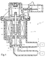
- numeral 1 indicates a canister purge solenoid valve for an internal combustion engine as a whole.
- the canister purge solenoid valve 1 is of the ON/OFF type and is adapted to be controlled to either allow or prevent a passage of fuel vapors through a canister circuit 2 which connects a fuel tank 3 to an intake system 4 of the internal combustion engine.
- a canister circuit 2 which connects a fuel tank 3 to an intake system 4 of the internal combustion engine.
- an inlet port 5 of the canister purge solenoid valve 1 communicates with the fuel tank 3, whereas an outlet port 6 of the canister purge solenoid valve 1 communicates with the intake system 4.
- the canister purge solenoid valve 1 essentially has a cylindrical symmetry about a longitudinal axis 7 and comprises a housing 8, which has a cylindrical tubular shape with variable section along longitudinal axis 7 and centrally has a supply channel 9 which connects the inlet port 5 to the outlet port 6 and is crossed in use by the fuel vapors.
- annular shaped valve seat 10 is obtained across supply channel 9 against which annular shaped valve seat 10 a disc-like valve shutter 11 rests in order to seal the supply channel 9, and thus prevent the fuel vapor flow through the supply channel 9 itself.
- the disc-like valve shutter 11 is movably fitted in the housing 8 to axially move from an open position (shown in figures 1 and 4 ), in which the disc-like valve shutter 11 is axially distant from the valve seat 10 and thus the fuel vapors may flow through a main annular meatus 12 defined between the disc-like valve shutter 11 and the valve seat 10, to a closed position (shown in figure 2 ), in which the disc-like valve shutter 11 is pressed against the valve seat 10 in order to seal supply channel 9, and thus prevent the fuel vapor flow through the supply channel 9 itself.
- An electromagnetic actuator 13 is arranged in the housing 8 and comprises a fixed magnetic armature 14, which is rigidly coupled to the housing 8, a winding 15, which is inserted in the magnetic armature 14, and a mobile keeper 16, which is magnetically coupled to the fixed magnetic armature 14, mechanically integral to the disc-like valve shutter 11, and axially movable in order to move the disc-like valve shutter 11 from the open position (shown in figures 1 and 4 ) to the closed position (shown in figure 2 ).
- a latch spring 17 which pushes the mobile keeper 16 (and thus the disc-like valve shutter 11) towards the closed position (shown in figure 2 ) acts on the mobile keeper 16 (and thus on the disc-like valve shutter 11 which is mechanically connected to the mobile keeper 16).
- the mobile keeper 16 and the latch spring 17 are mechanically connected to the disc-like valve shutter 11 by means of a rigid stem 18 which is developed axially (i.e. parallel to the longitudinal axis 7); in particular, an upper end of the stem 18 is coupled to the latch spring 17, a central portion of the stem 18 is coupled to the mobile keeper 16 and a lower end of the stem 18 is coupled to the disc-like valve shutter 11.
- the disc-like valve shutter 11 has a through pressure compensating channel 19, which is arranged axially in central position; therefore, the through pressure compensating channel 19 is arranged in the valve seat 10, i.e. the annular valve seat 10 is arranged around the pressure compensating channel 19.
- the pressure compensating channel 19 connects the two sides of the supply channel 9 separated by the disc-like valve shutter 11 (in other words, the pressure compensating channel 19 connects the side upstream of the valve seat 10 to the side downstream of the valve seat 10), by bypassing, in some moments and as will be explained in greater detail below, the sealing achieved by the contact between the disc-like valve shutter 11 and the valve seat 10 itself.
- the stem 18 is arranged through the pressure compensating channel 19, i.e. the stem 18 passes through the pressure compensating channel 19.
- An intermediate portion 20 of the stem 18 is arranged in the pressure compensating channel 19 and has an external diameter which is smaller than the internal diameter of the pressure compensating channel 19 so as to leave a secondary annular meatus 21 free in the pressure compensating channel 19 through which the fuel vapors may flow, in some moments and as will be explained in greater detail below.
- the stem 18 has a bulging bottom portion 22 which inferiorly delimits the intermediate portion 20, is arranged outside the pressure compensating channel 19 and close to the lower opening 23 of the pressure compensating channel 19, and has an external diameter which is larger than the internal diameter of the pressure compensating channel 19 itself.
- the disc-shaped valve shutter 11 is provided with a lower annular gasket 24, which is arranged around the lower opening 23 of the pressure compensating channel 19 and has three ports 25 (i.e. three missing portions as shown in figure 6 ) through which the fuel vapors may pass when the bulging bottom portion 22 of the stem 18 rests on the lower gasket 24 itself.
- the lower gasket 24 is shaped so as to be "permeable", i.e.
- the stem 18 has a bulging top portion 26 which superiorly delimits the intermediate portion 20, is arranged outside the pressure compensating channel 19 and close to the top opening 27 of the pressure compensating channel 19, and has an external diameter which is larger than the internal diameter of the pressure compensating channel 19.
- the disc-like valve shutter 11 is provided with an annular upper gasket 28 which is arranged around the top opening 27 of the pressure compensating channel 19 and seals the top opening 27 when the bulging top portion 26 of the stem 18 rests on the upper seal 28 itself.
- the upper gasket 28 is seamless (unlike the upper gasket 24, which has the three ports 25) because the main function of the upper gasket 28 is to ensure the sealing of the contact between the bulging top portion 26 of the stem 18 and the top opening 27 of the pressure compensating channel 18.
- the stem 18 is not rigidly integral to the disc-like valve shutter 11 and may thus perform relative movements with respect to the disc-like valve shutter 11 itself.
- the stem 18 is not rigidly restrained to the disc-like valve shutter 11 and thus the stem 18 may "reel” with respect to the disc-like valve shutter 11 (or vice versa) within the limits set by the bulging top portion 26 and by the bulging bottom portion 22 of the stem 18 which constitute "stops".
- the axial dimension of the intermediate portion 20, i.e. the axial distance existing between the bulging top portion 26 of the stem 18 and the bulging bottom portion 22 of the stem 18, is greater than the thickness (i.e. the axial dimension) of the disc-shaped valve shutter 11 and therefore the disc-shaped valve shutter 11 is mechanically free to move with respect to the stem 18 within the limits set by the bulging top portion 26 and by the bulging bottom portion 22 themselves.
- the disc-like valve shutter 11 is provided with an external annular gasket 29 which is arranged at the valve seat 10 and which rests on the valve seat 10 itself when the valve shutter (11) is in the closed position.
- the latch spring 17 axially pushes the stem 18 downwards and the stem 18 presses the disc-like valve shutter 11 against the valve seat 10 keeping the disc-like valve shutter 11 itself in the closed position (shown in figure 2 ); in this position, the bulging top portion 26 in the stem 18 rests against the portion of the disc-like valve shutter 11 which surrounds the top opening 27 of the pressure compensating channel 19, thus pressing the disc-like valve shutter 11 against the valve seat 10.
- the disc-like valve shutter 11 seals (i.e. tightly closes) the supply channel 9 and thus prevents the flow of fuel vapors through the supply channel 9.
- the electromagnetic actuator 13 When the electromagnetic actuator 13 is activated (i.e. energized), the magnetic attraction force generated by the electromagnetic actuator 13 directed upwards overcomes the elastic force generated by the latch spring 17 directed downwards, and thus the stem 18 move axially upwards.
- the stem 18 does not exert any mechanical action on the disc-like valve shutter 11 because in such a first part of the movement the bulging top portion 26 of the stem 18 separates from the portion of the disc-like valve shutter 11 which surrounds the top opening 27 of the pressure compensating channel 19 while the bulging bottom portion 22 of the stem 18 approaches (but still without contact) the portion of the disc-like valve shutter 11 which surrounds the lower opening 23 of the pressure compensating channel 19.
- the stem 18 is in an intermediate position (shown in figure 3 ), in which the disc-like valve shutter 11 is still in contact with the valve seat 10 and in which both openings 23 and 27 of the pressure compensating channel 19 are (at least partially) free, i.e. they are not completely sealed by the bulging portions 22 and 26 of the stem 18.
- the pressure compensating channel 19 is open (i.e. fuel vapors may flow through it) and connects the two sides of the supply channel 9 separated by the disc-like valve shutter 11; therefore, a compensation of the pressure occurs (nearly instantaneously) in this intermediate position (shown in figure 3 ) in the sides of the supply channel 9 separated by the disc-like valve shutter 11, i.e.
- the upwards movement of the stem 18 brings the bulging bottom portion 22 into contact with the disc-like valve shutter 11 which surrounds the lower opening 23 of the pressure compensating channel 19 (i.e. into contact with the lower gasket 24) and thus the stem 18 starts pulling the disc-like valve shutter 11 axially upwards, thus moving the disc-like valve shutter 11 towards the opening position (shown in figures 1 and 4 ), wherein the disc-like valve shutter 11 is axially distant from the valve seat 10 and therefore the fuel vapors may flow through the main annular meatus 12 defined between the disc-like valve shutter 11 and the valve seat 10.
- the canister purge solenoid valve 1 described above has many advantages.
- the canister solenoid valve 1 described above has a main annular meatus 12 of considerable size (by virtue of a disc-like valve shutter 11 having a large diameter) and therefore allows to achieve high flow rates despite the low pressure drops caused by the crossing of the canister purge solenoid valve 1 itself.
- the canister purge solenoid valve 1 described above allows to use a low performance electromagnetic actuator 13 (consequently of small size, low cost and low weight), because the force applied by the electromagnetic actuator 13 on the disc-like valve shutter 11 (i.e. net of the elastic force generated by the latch spring 17) does not need to overcome a significant pneumatic force: an upstream/downstream pressure difference of the disc-like valve shutter 11 exists only until the stem 18 reaches the intermediate position (shown in figure 3 ), and in such a part of the movement of the stem 18 the area involved by the movement is very small (a small fraction of the overall area of the disc-like valve shutter 11) and therefore the generated pneumatic force which must be overcome to move the stem 18 which is generated by the pressure difference upstream/downstream of the disc-like valve shutter 11 is in all cases very small (being proportional to the pressure difference and the overall area).
- canister purge solenoid valve 1 described above is easily and cost-effectively producible in that it doesn't require any additional actuator or additional component of complex shape with respect to a similar canister purge solenoid valve 1 of the known type.
Applications Claiming Priority (1)
| Application Number | Priority Date | Filing Date | Title |
|---|---|---|---|
| IT000563A ITBO20110563A1 (it) | 2011-10-03 | 2011-10-03 | Valvola canister con forza di attuazione ridotta |
Publications (2)
| Publication Number | Publication Date |
|---|---|
| EP2581596A1 true EP2581596A1 (fr) | 2013-04-17 |
| EP2581596B1 EP2581596B1 (fr) | 2014-12-03 |
Family
ID=44936342
Family Applications (1)
| Application Number | Title | Priority Date | Filing Date |
|---|---|---|---|
| EP12187129.7A Not-in-force EP2581596B1 (fr) | 2011-10-03 | 2012-10-03 | Vanne de purge de contenant à faible force d'actionnement |
Country Status (5)
| Country | Link |
|---|---|
| US (1) | US20130133628A1 (fr) |
| EP (1) | EP2581596B1 (fr) |
| CN (1) | CN103047422B (fr) |
| BR (1) | BR102012025255A2 (fr) |
| IT (1) | ITBO20110563A1 (fr) |
Cited By (1)
| Publication number | Priority date | Publication date | Assignee | Title |
|---|---|---|---|---|
| WO2015007565A1 (fr) * | 2013-07-16 | 2015-01-22 | Robert Bosch Gmbh | Système de vannes |
Families Citing this family (14)
| Publication number | Priority date | Publication date | Assignee | Title |
|---|---|---|---|---|
| US9950202B2 (en) | 2013-02-01 | 2018-04-24 | 3M Innovative Properties Company | Respirator negative pressure fit check devices and methods |
| US9517367B2 (en) | 2013-02-01 | 2016-12-13 | 3M Innovative Properties Company | Respiratory mask having a clean air inlet chamber |
| US11052268B2 (en) | 2013-02-01 | 2021-07-06 | 3M Innovative Properties Company | Respirator negative pressure fit check devices and methods |
| DE102014213511A1 (de) * | 2014-07-11 | 2016-01-14 | Robert Bosch Gmbh | Ventil und Verfahren zum Freigeben/Verschließen einer Fluidpassage |
| JP2017532489A (ja) * | 2014-09-24 | 2017-11-02 | イートン コーポレーションEaton Corporation | 電子制御燃料システムモジュール |
| US11698045B2 (en) | 2014-09-24 | 2023-07-11 | Eaton Intelligent Power Limited | Electrically controlled fuel system module |
| USD816209S1 (en) | 2016-03-28 | 2018-04-24 | 3M Innovative Properties Company | Respirator inlet port connection seal |
| USD827810S1 (en) | 2016-03-28 | 2018-09-04 | 3M Innovative Properties Company | Hardhat suspension adapter for half facepiece respirators |
| US11020619B2 (en) | 2016-03-28 | 2021-06-01 | 3M Innovative Properties Company | Multiple chamber respirator sealing devices and methods |
| US11219787B2 (en) | 2016-03-28 | 2022-01-11 | 3M Innovative Properties Company | Respirator fit check sealing devices and methods |
| USD842982S1 (en) | 2016-03-28 | 2019-03-12 | 3M Innovative Properties Company | Hardhat suspension adapter for half facepiece respirators |
| WO2017200636A2 (fr) | 2016-05-16 | 2017-11-23 | Eaton Corporation | Système électronique de gestion des émissions par évaporation |
| JP6915585B2 (ja) * | 2017-06-07 | 2021-08-04 | 浜名湖電装株式会社 | 弁装置および燃料蒸発ガスパージシステム |
| US11565355B2 (en) * | 2021-04-13 | 2023-01-31 | Eto Magnetic Gmbh | Poppet valve device, canister vent solenoid and method for improving a poppet valve sealing efficiency |
Citations (4)
| Publication number | Priority date | Publication date | Assignee | Title |
|---|---|---|---|---|
| EP0631075A1 (fr) | 1993-06-16 | 1994-12-28 | SAGEM ALLUMAGE Société Anonyme | Electrovanne à double siège, et circuit de recyclage de vapeurs d'essence comportant un tel clapet |
| EP0713036A1 (fr) * | 1994-11-17 | 1996-05-22 | Sagem Sa | Clapet d'électrovanne et circuit de recyclage de vapeurs d'essence de moteur à combustion interne |
| US20020088441A1 (en) * | 2000-08-08 | 2002-07-11 | Craig Weldon | Evaporative emission control system including a fuel tank isolation valve |
| US20050056088A1 (en) * | 2003-09-16 | 2005-03-17 | Hurley Darrin W. | Evaporative emission system integrity module |
Family Cites Families (16)
| Publication number | Priority date | Publication date | Assignee | Title |
|---|---|---|---|---|
| FR809667A (fr) * | 1936-08-19 | 1937-03-08 | Bretagne Atel Chantiers | Soupape équilibrée pour distributeurs de fluide sous pression |
| US3572382A (en) * | 1969-01-31 | 1971-03-23 | Fred J Luthe | Single-ported double-seated valve mechanism |
| US3797526A (en) * | 1972-08-21 | 1974-03-19 | E Champeon | Cage valve with pilot and mechanical operating means |
| JPS555823Y2 (fr) * | 1974-06-29 | 1980-02-09 | ||
| NO172410C (no) * | 1991-04-04 | 1993-07-14 | Covent As | Ventil for stroemmende medium i vaeskeform |
| US5137055A (en) * | 1992-01-14 | 1992-08-11 | Yazaki Corporation | Stop valve |
| US6293266B1 (en) * | 1998-05-26 | 2001-09-25 | A. Kayser Automotive Systems Gmbh | Exhaust gas recirculation device |
| CN2403953Y (zh) * | 1999-12-10 | 2000-11-01 | 南京理工大学 | 液、气压力自平衡截止阀 |
| US6612338B2 (en) * | 2000-05-25 | 2003-09-02 | Siemens Automotive Inc. | Fuel tank pressure control valve |
| CN1322258C (zh) * | 2002-12-30 | 2007-06-20 | 西安重型机械研究所 | 一种大流量充、排液阀 |
| CN101317031B (zh) * | 2005-12-01 | 2013-03-27 | 博格华纳公司 | 控制阀 |
| CN201013908Y (zh) * | 2007-03-14 | 2008-01-30 | 济南市大秦机电设备有限公司 | 燃气紧急切断阀 |
| DE502007004515D1 (de) * | 2007-12-11 | 2010-09-02 | Elster Gmbh | Einrichtung zum Sperren und Freigeben einer Fluidströmung sowie zugehöriges Verfahren |
| US8256739B2 (en) * | 2008-12-22 | 2012-09-04 | Husco International, Inc. | Poppet valve operated by an electrohydraulic poppet pilot valve |
| GB0900063D0 (en) * | 2009-01-05 | 2009-02-11 | Madgal Csf Ltd | High flow valve |
| CN201599415U (zh) * | 2010-01-08 | 2010-10-06 | 科福龙阀门集团有限公司 | 正压内平衡截止阀 |
-
2011
- 2011-10-03 IT IT000563A patent/ITBO20110563A1/it unknown
-
2012
- 2012-09-29 CN CN201210379681.8A patent/CN103047422B/zh not_active Expired - Fee Related
- 2012-10-03 EP EP12187129.7A patent/EP2581596B1/fr not_active Not-in-force
- 2012-10-03 BR BR102012025255A patent/BR102012025255A2/pt not_active Application Discontinuation
- 2012-10-03 US US13/644,189 patent/US20130133628A1/en not_active Abandoned
Patent Citations (4)
| Publication number | Priority date | Publication date | Assignee | Title |
|---|---|---|---|---|
| EP0631075A1 (fr) | 1993-06-16 | 1994-12-28 | SAGEM ALLUMAGE Société Anonyme | Electrovanne à double siège, et circuit de recyclage de vapeurs d'essence comportant un tel clapet |
| EP0713036A1 (fr) * | 1994-11-17 | 1996-05-22 | Sagem Sa | Clapet d'électrovanne et circuit de recyclage de vapeurs d'essence de moteur à combustion interne |
| US20020088441A1 (en) * | 2000-08-08 | 2002-07-11 | Craig Weldon | Evaporative emission control system including a fuel tank isolation valve |
| US20050056088A1 (en) * | 2003-09-16 | 2005-03-17 | Hurley Darrin W. | Evaporative emission system integrity module |
Cited By (1)
| Publication number | Priority date | Publication date | Assignee | Title |
|---|---|---|---|---|
| WO2015007565A1 (fr) * | 2013-07-16 | 2015-01-22 | Robert Bosch Gmbh | Système de vannes |
Also Published As
| Publication number | Publication date |
|---|---|
| BR102012025255A2 (pt) | 2015-09-15 |
| ITBO20110563A1 (it) | 2013-04-04 |
| US20130133628A1 (en) | 2013-05-30 |
| CN103047422B (zh) | 2016-05-25 |
| EP2581596B1 (fr) | 2014-12-03 |
| CN103047422A (zh) | 2013-04-17 |
Similar Documents
| Publication | Publication Date | Title |
|---|---|---|
| EP2581596B1 (fr) | Vanne de purge de contenant à faible force d'actionnement | |
| US7270310B2 (en) | Electromagnetic valve and vapor fuel treating system applying the same | |
| US9200719B2 (en) | Fluid control valve device | |
| US9086161B2 (en) | Valve apparatus with positive and negative pressure relief valves | |
| EP1399662B1 (fr) | Systeme d'alimentation incorporant un appareil et un procede de gestion de la pression des vapeurs de carburant | |
| US20120255639A1 (en) | Solenoid valve | |
| JP6044493B2 (ja) | 流量切替弁 | |
| US20140197188A1 (en) | Ventilation device for the fuel system of a hybrid vehicle | |
| US10495232B2 (en) | Dual path dual purge valve system and valve assembly for turbo boosted engine | |
| US9376994B2 (en) | Valve assembly for an injection valve and injection valve | |
| US20150090355A1 (en) | Solenoid-Powered Gate Valve | |
| CN112654768B (zh) | 阀装置 | |
| JP2016031094A (ja) | 二段式切替弁 | |
| EP3665408B1 (fr) | Vanne entraînée par un moteur pas à pas pour commander une communication fluidique entre un réservoir de carburant et une cartouche | |
| US7086383B2 (en) | Permanent magnet digital purge valve | |
| EP3094897B1 (fr) | Robinet-vanne actionné par solénoïde | |
| CN208605418U (zh) | 一种先导式电磁开关阀 | |
| US9574532B2 (en) | Valve assembly and injection valve | |
| US9802479B2 (en) | Tank sealing valve and evaporation fuel processing device including the same | |
| KR101348570B1 (ko) | 작동성능이 향상되는 퍼지 컨트롤 솔레노이드 밸브 | |
| JP2890883B2 (ja) | 流体制御用電磁弁 | |
| JP2015007455A (ja) | 流量制御用電磁弁 | |
| CN218991746U (zh) | 机械阀、碳罐脱附装置、发动机总成和车辆 | |
| US9777677B2 (en) | Valve for ventilation of a tank | |
| JPH08312827A (ja) | 電磁弁 |
Legal Events
| Date | Code | Title | Description |
|---|---|---|---|
| PUAI | Public reference made under article 153(3) epc to a published international application that has entered the european phase |
Free format text: ORIGINAL CODE: 0009012 |
|
| AK | Designated contracting states |
Kind code of ref document: A1 Designated state(s): AL AT BE BG CH CY CZ DE DK EE ES FI FR GB GR HR HU IE IS IT LI LT LU LV MC MK MT NL NO PL PT RO RS SE SI SK SM TR |
|
| AX | Request for extension of the european patent |
Extension state: BA ME |
|
| 17P | Request for examination filed |
Effective date: 20130723 |
|
| RIC1 | Information provided on ipc code assigned before grant |
Ipc: F16K 31/06 20060101ALI20140327BHEP Ipc: F16K 1/44 20060101ALI20140327BHEP Ipc: F02M 25/08 20060101AFI20140327BHEP |
|
| GRAP | Despatch of communication of intention to grant a patent |
Free format text: ORIGINAL CODE: EPIDOSNIGR1 |
|
| INTG | Intention to grant announced |
Effective date: 20140526 |
|
| GRAS | Grant fee paid |
Free format text: ORIGINAL CODE: EPIDOSNIGR3 |
|
| GRAA | (expected) grant |
Free format text: ORIGINAL CODE: 0009210 |
|
| AK | Designated contracting states |
Kind code of ref document: B1 Designated state(s): AL AT BE BG CH CY CZ DE DK EE ES FI FR GB GR HR HU IE IS IT LI LT LU LV MC MK MT NL NO PL PT RO RS SE SI SK SM TR |
|
| REG | Reference to a national code |
Ref country code: GB Ref legal event code: FG4D |
|
| REG | Reference to a national code |
Ref country code: AT Ref legal event code: REF Ref document number: 699523 Country of ref document: AT Kind code of ref document: T Effective date: 20141215 Ref country code: CH Ref legal event code: EP |
|
| REG | Reference to a national code |
Ref country code: IE Ref legal event code: FG4D |
|
| REG | Reference to a national code |
Ref country code: DE Ref legal event code: R096 Ref document number: 602012004080 Country of ref document: DE Effective date: 20150115 |
|
| REG | Reference to a national code |
Ref country code: NL Ref legal event code: VDEP Effective date: 20141203 |
|
| REG | Reference to a national code |
Ref country code: AT Ref legal event code: MK05 Ref document number: 699523 Country of ref document: AT Kind code of ref document: T Effective date: 20141203 |
|
| PG25 | Lapsed in a contracting state [announced via postgrant information from national office to epo] |
Ref country code: NO Free format text: LAPSE BECAUSE OF FAILURE TO SUBMIT A TRANSLATION OF THE DESCRIPTION OR TO PAY THE FEE WITHIN THE PRESCRIBED TIME-LIMIT Effective date: 20150303 Ref country code: LT Free format text: LAPSE BECAUSE OF FAILURE TO SUBMIT A TRANSLATION OF THE DESCRIPTION OR TO PAY THE FEE WITHIN THE PRESCRIBED TIME-LIMIT Effective date: 20141203 Ref country code: NL Free format text: LAPSE BECAUSE OF FAILURE TO SUBMIT A TRANSLATION OF THE DESCRIPTION OR TO PAY THE FEE WITHIN THE PRESCRIBED TIME-LIMIT Effective date: 20141203 Ref country code: FI Free format text: LAPSE BECAUSE OF FAILURE TO SUBMIT A TRANSLATION OF THE DESCRIPTION OR TO PAY THE FEE WITHIN THE PRESCRIBED TIME-LIMIT Effective date: 20141203 Ref country code: ES Free format text: LAPSE BECAUSE OF FAILURE TO SUBMIT A TRANSLATION OF THE DESCRIPTION OR TO PAY THE FEE WITHIN THE PRESCRIBED TIME-LIMIT Effective date: 20141203 |
|
| REG | Reference to a national code |
Ref country code: LT Ref legal event code: MG4D |
|
| PG25 | Lapsed in a contracting state [announced via postgrant information from national office to epo] |
Ref country code: RS Free format text: LAPSE BECAUSE OF FAILURE TO SUBMIT A TRANSLATION OF THE DESCRIPTION OR TO PAY THE FEE WITHIN THE PRESCRIBED TIME-LIMIT Effective date: 20141203 Ref country code: SE Free format text: LAPSE BECAUSE OF FAILURE TO SUBMIT A TRANSLATION OF THE DESCRIPTION OR TO PAY THE FEE WITHIN THE PRESCRIBED TIME-LIMIT Effective date: 20141203 Ref country code: LV Free format text: LAPSE BECAUSE OF FAILURE TO SUBMIT A TRANSLATION OF THE DESCRIPTION OR TO PAY THE FEE WITHIN THE PRESCRIBED TIME-LIMIT Effective date: 20141203 Ref country code: CY Free format text: LAPSE BECAUSE OF FAILURE TO SUBMIT A TRANSLATION OF THE DESCRIPTION OR TO PAY THE FEE WITHIN THE PRESCRIBED TIME-LIMIT Effective date: 20141203 Ref country code: HR Free format text: LAPSE BECAUSE OF FAILURE TO SUBMIT A TRANSLATION OF THE DESCRIPTION OR TO PAY THE FEE WITHIN THE PRESCRIBED TIME-LIMIT Effective date: 20141203 Ref country code: GR Free format text: LAPSE BECAUSE OF FAILURE TO SUBMIT A TRANSLATION OF THE DESCRIPTION OR TO PAY THE FEE WITHIN THE PRESCRIBED TIME-LIMIT Effective date: 20150304 Ref country code: AT Free format text: LAPSE BECAUSE OF FAILURE TO SUBMIT A TRANSLATION OF THE DESCRIPTION OR TO PAY THE FEE WITHIN THE PRESCRIBED TIME-LIMIT Effective date: 20141203 |
|
| PG25 | Lapsed in a contracting state [announced via postgrant information from national office to epo] |
Ref country code: CZ Free format text: LAPSE BECAUSE OF FAILURE TO SUBMIT A TRANSLATION OF THE DESCRIPTION OR TO PAY THE FEE WITHIN THE PRESCRIBED TIME-LIMIT Effective date: 20141203 Ref country code: EE Free format text: LAPSE BECAUSE OF FAILURE TO SUBMIT A TRANSLATION OF THE DESCRIPTION OR TO PAY THE FEE WITHIN THE PRESCRIBED TIME-LIMIT Effective date: 20141203 Ref country code: RO Free format text: LAPSE BECAUSE OF FAILURE TO SUBMIT A TRANSLATION OF THE DESCRIPTION OR TO PAY THE FEE WITHIN THE PRESCRIBED TIME-LIMIT Effective date: 20141203 Ref country code: PT Free format text: LAPSE BECAUSE OF FAILURE TO SUBMIT A TRANSLATION OF THE DESCRIPTION OR TO PAY THE FEE WITHIN THE PRESCRIBED TIME-LIMIT Effective date: 20150403 Ref country code: SK Free format text: LAPSE BECAUSE OF FAILURE TO SUBMIT A TRANSLATION OF THE DESCRIPTION OR TO PAY THE FEE WITHIN THE PRESCRIBED TIME-LIMIT Effective date: 20141203 |
|
| PG25 | Lapsed in a contracting state [announced via postgrant information from national office to epo] |
Ref country code: IS Free format text: LAPSE BECAUSE OF FAILURE TO SUBMIT A TRANSLATION OF THE DESCRIPTION OR TO PAY THE FEE WITHIN THE PRESCRIBED TIME-LIMIT Effective date: 20150403 Ref country code: PL Free format text: LAPSE BECAUSE OF FAILURE TO SUBMIT A TRANSLATION OF THE DESCRIPTION OR TO PAY THE FEE WITHIN THE PRESCRIBED TIME-LIMIT Effective date: 20141203 |
|
| REG | Reference to a national code |
Ref country code: DE Ref legal event code: R097 Ref document number: 602012004080 Country of ref document: DE |
|
| PLBE | No opposition filed within time limit |
Free format text: ORIGINAL CODE: 0009261 |
|
| STAA | Information on the status of an ep patent application or granted ep patent |
Free format text: STATUS: NO OPPOSITION FILED WITHIN TIME LIMIT |
|
| PG25 | Lapsed in a contracting state [announced via postgrant information from national office to epo] |
Ref country code: DK Free format text: LAPSE BECAUSE OF FAILURE TO SUBMIT A TRANSLATION OF THE DESCRIPTION OR TO PAY THE FEE WITHIN THE PRESCRIBED TIME-LIMIT Effective date: 20141203 |
|
| 26N | No opposition filed |
Effective date: 20150904 |
|
| PG25 | Lapsed in a contracting state [announced via postgrant information from national office to epo] |
Ref country code: SI Free format text: LAPSE BECAUSE OF FAILURE TO SUBMIT A TRANSLATION OF THE DESCRIPTION OR TO PAY THE FEE WITHIN THE PRESCRIBED TIME-LIMIT Effective date: 20141203 |
|
| PG25 | Lapsed in a contracting state [announced via postgrant information from national office to epo] |
Ref country code: BE Free format text: LAPSE BECAUSE OF FAILURE TO SUBMIT A TRANSLATION OF THE DESCRIPTION OR TO PAY THE FEE WITHIN THE PRESCRIBED TIME-LIMIT Effective date: 20141203 Ref country code: LU Free format text: LAPSE BECAUSE OF FAILURE TO SUBMIT A TRANSLATION OF THE DESCRIPTION OR TO PAY THE FEE WITHIN THE PRESCRIBED TIME-LIMIT Effective date: 20151003 |
|
| REG | Reference to a national code |
Ref country code: CH Ref legal event code: PL |
|
| PG25 | Lapsed in a contracting state [announced via postgrant information from national office to epo] |
Ref country code: MC Free format text: LAPSE BECAUSE OF FAILURE TO SUBMIT A TRANSLATION OF THE DESCRIPTION OR TO PAY THE FEE WITHIN THE PRESCRIBED TIME-LIMIT Effective date: 20141203 |
|
| REG | Reference to a national code |
Ref country code: IE Ref legal event code: MM4A |
|
| PG25 | Lapsed in a contracting state [announced via postgrant information from national office to epo] |
Ref country code: LI Free format text: LAPSE BECAUSE OF NON-PAYMENT OF DUE FEES Effective date: 20151031 Ref country code: CH Free format text: LAPSE BECAUSE OF NON-PAYMENT OF DUE FEES Effective date: 20151031 |
|
| REG | Reference to a national code |
Ref country code: FR Ref legal event code: PLFP Year of fee payment: 5 |
|
| PG25 | Lapsed in a contracting state [announced via postgrant information from national office to epo] |
Ref country code: IE Free format text: LAPSE BECAUSE OF NON-PAYMENT OF DUE FEES Effective date: 20151003 |
|
| PGFP | Annual fee paid to national office [announced via postgrant information from national office to epo] |
Ref country code: TR Payment date: 20160927 Year of fee payment: 5 |
|
| PG25 | Lapsed in a contracting state [announced via postgrant information from national office to epo] |
Ref country code: SM Free format text: LAPSE BECAUSE OF FAILURE TO SUBMIT A TRANSLATION OF THE DESCRIPTION OR TO PAY THE FEE WITHIN THE PRESCRIBED TIME-LIMIT Effective date: 20141203 Ref country code: BG Free format text: LAPSE BECAUSE OF FAILURE TO SUBMIT A TRANSLATION OF THE DESCRIPTION OR TO PAY THE FEE WITHIN THE PRESCRIBED TIME-LIMIT Effective date: 20141203 Ref country code: HU Free format text: LAPSE BECAUSE OF FAILURE TO SUBMIT A TRANSLATION OF THE DESCRIPTION OR TO PAY THE FEE WITHIN THE PRESCRIBED TIME-LIMIT; INVALID AB INITIO Effective date: 20121003 |
|
| GBPC | Gb: european patent ceased through non-payment of renewal fee |
Effective date: 20161003 |
|
| PG25 | Lapsed in a contracting state [announced via postgrant information from national office to epo] |
Ref country code: GB Free format text: LAPSE BECAUSE OF NON-PAYMENT OF DUE FEES Effective date: 20161003 |
|
| PG25 | Lapsed in a contracting state [announced via postgrant information from national office to epo] |
Ref country code: MT Free format text: LAPSE BECAUSE OF FAILURE TO SUBMIT A TRANSLATION OF THE DESCRIPTION OR TO PAY THE FEE WITHIN THE PRESCRIBED TIME-LIMIT Effective date: 20141203 |
|
| REG | Reference to a national code |
Ref country code: FR Ref legal event code: PLFP Year of fee payment: 6 |
|
| PG25 | Lapsed in a contracting state [announced via postgrant information from national office to epo] |
Ref country code: MK Free format text: LAPSE BECAUSE OF FAILURE TO SUBMIT A TRANSLATION OF THE DESCRIPTION OR TO PAY THE FEE WITHIN THE PRESCRIBED TIME-LIMIT Effective date: 20141203 |
|
| REG | Reference to a national code |
Ref country code: FR Ref legal event code: PLFP Year of fee payment: 7 |
|
| PG25 | Lapsed in a contracting state [announced via postgrant information from national office to epo] |
Ref country code: AL Free format text: LAPSE BECAUSE OF FAILURE TO SUBMIT A TRANSLATION OF THE DESCRIPTION OR TO PAY THE FEE WITHIN THE PRESCRIBED TIME-LIMIT Effective date: 20141203 |
|
| PGFP | Annual fee paid to national office [announced via postgrant information from national office to epo] |
Ref country code: IT Payment date: 20190918 Year of fee payment: 8 Ref country code: FR Payment date: 20190919 Year of fee payment: 8 |
|
| PGFP | Annual fee paid to national office [announced via postgrant information from national office to epo] |
Ref country code: DE Payment date: 20190918 Year of fee payment: 8 |
|
| REG | Reference to a national code |
Ref country code: DE Ref legal event code: R119 Ref document number: 602012004080 Country of ref document: DE |
|
| PG25 | Lapsed in a contracting state [announced via postgrant information from national office to epo] |
Ref country code: DE Free format text: LAPSE BECAUSE OF NON-PAYMENT OF DUE FEES Effective date: 20210501 Ref country code: FR Free format text: LAPSE BECAUSE OF NON-PAYMENT OF DUE FEES Effective date: 20201031 |
|
| PG25 | Lapsed in a contracting state [announced via postgrant information from national office to epo] |
Ref country code: IT Free format text: LAPSE BECAUSE OF NON-PAYMENT OF DUE FEES Effective date: 20201003 |
|
| PG25 | Lapsed in a contracting state [announced via postgrant information from national office to epo] |
Ref country code: TR Free format text: LAPSE BECAUSE OF NON-PAYMENT OF DUE FEES Effective date: 20171003 |