EP2581462A1 - Blaslanze mit Direktzündung durch zurückziehbare Zündlanze - Google Patents
Blaslanze mit Direktzündung durch zurückziehbare Zündlanze Download PDFInfo
- Publication number
- EP2581462A1 EP2581462A1 EP11184493.2A EP11184493A EP2581462A1 EP 2581462 A1 EP2581462 A1 EP 2581462A1 EP 11184493 A EP11184493 A EP 11184493A EP 2581462 A1 EP2581462 A1 EP 2581462A1
- Authority
- EP
- European Patent Office
- Prior art keywords
- lance
- oxygen
- ignition device
- ignition
- guide
- Prior art date
- Legal status (The legal status is an assumption and is not a legal conclusion. Google has not performed a legal analysis and makes no representation as to the accuracy of the status listed.)
- Granted
Links
- 0 C1**2=C=C2C1 Chemical compound C1**2=C=C2C1 0.000 description 2
Images




Classifications
-
- C—CHEMISTRY; METALLURGY
- C21—METALLURGY OF IRON
- C21C—PROCESSING OF PIG-IRON, e.g. REFINING, MANUFACTURE OF WROUGHT-IRON OR STEEL; TREATMENT IN MOLTEN STATE OF FERROUS ALLOYS
- C21C5/00—Manufacture of carbon-steel, e.g. plain mild steel, medium carbon steel or cast steel or stainless steel
- C21C5/28—Manufacture of steel in the converter
- C21C5/42—Constructional features of converters
- C21C5/46—Details or accessories
- C21C5/48—Bottoms or tuyéres of converters
-
- C—CHEMISTRY; METALLURGY
- C21—METALLURGY OF IRON
- C21C—PROCESSING OF PIG-IRON, e.g. REFINING, MANUFACTURE OF WROUGHT-IRON OR STEEL; TREATMENT IN MOLTEN STATE OF FERROUS ALLOYS
- C21C5/00—Manufacture of carbon-steel, e.g. plain mild steel, medium carbon steel or cast steel or stainless steel
- C21C5/28—Manufacture of steel in the converter
- C21C5/30—Regulating or controlling the blowing
- C21C5/32—Blowing from above
-
- C—CHEMISTRY; METALLURGY
- C21—METALLURGY OF IRON
- C21C—PROCESSING OF PIG-IRON, e.g. REFINING, MANUFACTURE OF WROUGHT-IRON OR STEEL; TREATMENT IN MOLTEN STATE OF FERROUS ALLOYS
- C21C5/00—Manufacture of carbon-steel, e.g. plain mild steel, medium carbon steel or cast steel or stainless steel
- C21C5/28—Manufacture of steel in the converter
- C21C5/42—Constructional features of converters
- C21C5/46—Details or accessories
-
- C—CHEMISTRY; METALLURGY
- C21—METALLURGY OF IRON
- C21C—PROCESSING OF PIG-IRON, e.g. REFINING, MANUFACTURE OF WROUGHT-IRON OR STEEL; TREATMENT IN MOLTEN STATE OF FERROUS ALLOYS
- C21C5/00—Manufacture of carbon-steel, e.g. plain mild steel, medium carbon steel or cast steel or stainless steel
- C21C5/28—Manufacture of steel in the converter
- C21C5/42—Constructional features of converters
- C21C5/46—Details or accessories
- C21C5/4606—Lances or injectors
-
- C—CHEMISTRY; METALLURGY
- C21—METALLURGY OF IRON
- C21C—PROCESSING OF PIG-IRON, e.g. REFINING, MANUFACTURE OF WROUGHT-IRON OR STEEL; TREATMENT IN MOLTEN STATE OF FERROUS ALLOYS
- C21C7/00—Treating molten ferrous alloys, e.g. steel, not covered by groups C21C1/00 - C21C5/00
- C21C7/04—Removing impurities by adding a treating agent
- C21C7/072—Treatment with gases
-
- F—MECHANICAL ENGINEERING; LIGHTING; HEATING; WEAPONS; BLASTING
- F27—FURNACES; KILNS; OVENS; RETORTS
- F27D—DETAILS OR ACCESSORIES OF FURNACES, KILNS, OVENS OR RETORTS, IN SO FAR AS THEY ARE OF KINDS OCCURRING IN MORE THAN ONE KIND OF FURNACE
- F27D3/00—Charging; Discharging; Manipulation of charge
- F27D3/16—Introducing a fluid jet or current into the charge
-
- C—CHEMISTRY; METALLURGY
- C21—METALLURGY OF IRON
- C21C—PROCESSING OF PIG-IRON, e.g. REFINING, MANUFACTURE OF WROUGHT-IRON OR STEEL; TREATMENT IN MOLTEN STATE OF FERROUS ALLOYS
- C21C7/00—Treating molten ferrous alloys, e.g. steel, not covered by groups C21C1/00 - C21C5/00
- C21C7/10—Handling in a vacuum
-
- F—MECHANICAL ENGINEERING; LIGHTING; HEATING; WEAPONS; BLASTING
- F27—FURNACES; KILNS; OVENS; RETORTS
- F27B—FURNACES, KILNS, OVENS OR RETORTS IN GENERAL; OPEN SINTERING OR LIKE APPARATUS
- F27B3/00—Hearth-type furnaces, e.g. of reverberatory type; Electric arc furnaces ; Tank furnaces
- F27B3/10—Details, accessories or equipment, e.g. dust-collectors, specially adapted for hearth-type furnaces
- F27B3/22—Arrangements of air or gas supply devices
Definitions
- Such a lance is for example from the DE 10 2010 007 119 B3 known.
- oxygen is blown onto the molten metal.
- the oxygen is often applied to the molten metal by means of an oxygen lance.
- the vacuum vessel receiving the molten metal Before the vacuum treatment, the vacuum vessel receiving the molten metal must be preheated. Again, the lance is often used. This is possible because in addition to the oxygen guide a fuel gas guide is present in the outer jacket of the lance and thus the lance can be used not only as an oxygen lance, but also as a fire lance.
- the ignition of the ignitable gas mixture emerging from the lance takes place from oxygen and fuel gas by means of an additional, smaller burner (auxiliary burner, pilot burner).
- the pilot burner in turn is ignited by the igniter and the ignition lance through the sparks. Only the pilot flame of the pilot burner ignites the flame of the lance used as a fire lance.
- the pilot burner is arranged in the vicinity of the discharge end of the lance.
- the pilot burner is therefore exposed to the ambient conditions in which the lance is in total.
- this can lead to metal splashes or slag spatters getting into the pilot burner or to the pilot burner.
- Such splashes can lead to failure of the pilot burner and thus to a failure of the burner function of the lance.
- the lance must be time-consuming cleaned or replaced in such a case.
- the productivity loss occurring here and often also the thermal change of the molten metal during this time are disadvantageous.
- the object of the present invention is to develop a lance of the type mentioned in such a way that in a simple and reliable way ignition of the resulting at the discharge end combustible mixture is possible.
- the ignition device extends parallel to the Blaslanzenldicasachse and that the ignition device is displaceable parallel to the Blaslanzenl mecanicsachse.
- This embodiment of the lance is particularly easy to implement.
- the firing tip of the ignition device may protrude in the extended position on the discharge end of the lance and retracted in the retracted position behind the discharge end of the lance. In this case, an "external" ignition of the gas mixture, ie outside the lance.
- the ignition device is arranged next to the oxygen guide.
- the oxygen guide has an expansion region at the discharge end, it is also possible for the ignition device to project into the widening region in the extended position.
- the oxygen guide at the discharge end has a widening region and the ignition device protrudes in the extended position in the widening region, it may also be possible that the firing tip of the ignition device in the extended position does not protrude beyond the discharge end of the lance.
- an "internal" ignition so an ignition is still within the oxygen guide.
- at least one of the fuel gas exits must be arranged in the oxygen guide, so that the mixing region is still arranged within the oxygen guide.
- At least one of the fuel gas outlets is arranged in the oxygen guide, so that the mixing region is still arranged within the oxygen guide, it is also possible that a guide channel for guiding the ignition device is opened via a lateral recess to the mixing region and the firing tip of the ignition device is arranged in the extended position in the region of the recess. In this case, the ignition device is also protected in the extended position substantially before the radiant heat of the molten metal and the combustion flame of the lance.
- the last-mentioned embodiment ie the provision of a guide channel with a lateral recess towards the mixing region, can be realized independently of whether or not the oxygen guide has a widening region.
- the oxygen guide has the expansion area.
- the ignition device is bent.
- the firing tip of the ignition device in the extended position can easily protrude into the mixing region and be withdrawn from the mixing region in the retracted position.
- the ignition device may, for example, extend helically around an ignition device longitudinal axis, the ignition device longitudinal axis extending parallel to the longitudinal axis of the blowing lance at a constant distance from the longitudinal axis of the lance of the lance.
- the ignition device may be formed in a circular arc.
- the ignition device is designed as a conventional pilot burner, at whose firing tip a flame ignites the combustible gas mixture.
- the ignition device is designed as an ignition lance, whose firing tip generates sparks.
- an ignition device is connected to the ignition lance for providing voltage pulses necessary for the generation of the ignition spark.
- the ignitor can be designed, for example, as a capacitor-fed semiconductor ignition device.
- the ignitor is connected to the ignition lance via a cable.
- the ignitor does not have to be arranged inside the blow lance itself.
- the protected area in the retracted position of the ignition device is covered towards the mixing area by means of a covering device.
- the reliability of the ignition device is further optimized.
- FIG. 1 has a vacuum treatment plant for a molten metal 1 - for example, a molten steel 1 - a melt container 2.
- the melt container 2 is according to FIG. 1 the molten metal 1.
- the melt container 2 is covered by a dome-shaped hood 3.
- the hood 3 is connected to a take-off device (not shown in the FIG), so that the molten metal 1 is substantially adjacent to a vacuum at its top.
- a blowout 4 a blowgun 5 oxygen 6 is supplied.
- the oxygen 6 reacts with the molten metal 1.
- As part of the chemical reaction resulting gases and the unreacted oxygen content are sucked by means of the take-off device.
- FIG. 2 shows the same vacuum treatment plant in a second operating state.
- this operating state is located in the melt container 2 no molten metal.
- the melt container 2 can also be covered by the hood 3 in this operating state. Alternatively, he can be open.
- the melt container 2 is heated by means of a flame 7, which is generated at the discharge end 4 of the lance 5.
- the lance 5 has an outer jacket 8.
- the lance 5 thus extends along the BlaslanzenlCodesachse. 9
- the outer jacket 8 is usually water-cooled. For this purpose, it has a feed connection 10 and a discharge connection 11, via which cooling water 12 is supplied to the outer casing 8 and, after flowing through the outer casing 8, is discharged again from the outer casing 8.
- the oxygen guide 13 has an oxygen outlet 14 at the outlet end 4. At the oxygen outlet 14, the oxygen 6 exits, which is fed via an oxygen feed port 15 in the oxygen guide 13.
- the oxygen guide 13 runs on the BlaslanzenlCodesachse 9. Furthermore, the oxygen guide 13 usually over a large part of the length of the lance 5 a constant cross-section. At the discharge end 4, however, the oxygen guide 13 often has a widening 16. In this area, the oxygen guide 13 widens conically.
- these embodiments ie the arrangement of the oxygen guide 13 on the BlaslanzenlCodesachse 9 and the presence of the widening 16, are not absolutely necessary.
- the fuel gas guide 17 has at the discharge end 4 a number of fuel gas outlets 18.
- a fuel gas 19 for example, methane, propane, butane or a combustible process gas - leak, which is fed to a fuel gas feed port 20 in the fuel gas 17.
- a fuel gas outlet 18 is present at the minimum case. In general, either a plurality of fuel gas outlets 18 are present or the fuel gas outlet 18 is formed as an annular gap.
- the fuel gas outlets 18 may be arranged at the discharge end 4 adjacent to the oxygen outlet 14. In general, however, the fuel gas outlets 18 are arranged in the oxygen guide 13. In particular, at least one of the fuel gas outlets 18 as shown by FIG. 3 be arranged in the expansion region 16 of the oxygen guide 13.
- the oxygen 6 supplied to the oxygen outlet 14 and the fuel gas 19 emerging at the fuel gas outlet 18 mix in a mixing region 21 to form a combustible and also ignitable gas mixture.
- the mixing area 21 may be as shown in FIG FIG. 3 still be disposed within the oxygen guide 13.
- the mixing region 21 can be arranged in the widening region 16 of the oxygen guide 13.
- the mixing region 21 - in particular in the event that the fuel gas outlets 18 are not arranged in the oxygen guide 13 - lie in front of the discharge end 4 of the lance 5.
- the gas mixture is ignited by means of an ignition device 22, which is arranged in the lance 5 for this purpose.
- the ignition device 22 in turn has - see in particular FIG. 4 - A firing tip 23, by means of which the thermal energy required to ignite the gas mixture is generated locally.
- the ignition device 22 is in particular according to the illustration of FIG. 3 disposed within the outer shell 8.
- the ignition device 22 is formed as an ignition lance 22, the firing tip 23 generates spark 24.
- the voltage pulses required to generate the sparks 24 are provided by an ignitor 25, which is connected to the ignition lance 22 for this purpose.
- the connection between the ignition lance 22 and the ignitor 25 may be rigid.
- the ignitor 25 is connected to the ignition lance 22 via a cable 26.
- the ignitor 25 is preferably designed as a capacitor-fed semiconductor ignition device.
- the electrical construction is off FIG. 5 seen.
- the ignitor 25 is connected to a voltage source U, for example, the general power supply with - depending on the state - a rated voltage of 100 V, 110 V or 230 V and a mains frequency of 50 Hz or 60 Hz.
- the voltage supplied by the voltage source U is in a transformer 27 up-converted and rectified in a rectifier 28. If the voltage source U outputs a DC voltage, the transformer 27 is preceded by an inverter.
- the rectified voltage is buffered in a capacitor unit 29.
- the capacitor unit 29 is a semiconductor switching device 30 downstream.
- the semiconductor switching device 30 in turn is - directly or via the cable 26 - connected to the ignition lance 22.
- ignitor 25 and ignition lance 22 With a suitable choice of ignitor 25 and ignition lance 22 a reliable generation of the spark 24 is ensured. This is true even if the firing tip 23 is dirty or covered with oil or grease. Suitable ignitors 25 and suitable ignition lances 22 are sold, for example, by DURAG GmbH, Hamburg, Germany.
- the present invention is explained below in connection with an ignition device 22 designed as an ignition lance 22.
- the ignition device 22 is designed as a pilot burner.
- the ignition lance 22 can be moved between an extended position and a retracted position. In the extended position, the firing tip 23 acts on the mixing region 21 with the ignition sparks 24 generated by it This position is the ignition lance 22 for igniting the combustible gas mixture.
- the ignition lance 22 In the retracted position, the ignition lance 22 is retracted into a protective region 31, in which the ignition lance 22 is protected against metal and slag splashes of the molten metal 1.
- the protection region 31 may be covered towards the mixing region 21 by means of a spring-loaded or forced-operated covering device 32.
- the ignition lance 22 is transferred after the ignition of the combustible gas mixture in the retracted position and remains there until a renewed ignition of the gas mixture is required.
- the protection area 31 may be formed as needed.
- the protection area 31 according to FIG. 6 be formed by a guide channel 33 which is adapted to the cross section of the ignition lance 22. It is even possible that the protection area 31 is completely open. In this case, the protection of the ignition lance 22 can simply result from the (compared to the extended position) greater distance of the ignition lance 22 and in particular the firing tip 23 of the molten metal 1.
- FIGS. 6 to 16 In particular, they all show the oxygen guide 13 including the widening region 16.
- the presence of the widening region 16 is always preferred. However, it is only in conjunction with the embodiments of FIGS. 8 to 10 and 12 absolutely necessary.
- FIGS. 6 to 16 Furthermore, they all show the fuel gas guide 17 and the fuel gas outlets 18. In particular, they show a plurality of fuel gas outlets 18. However, this is not mandatory. Furthermore, they show that the fuel gas outlets 18 are arranged in the oxygen guide 13, more precisely at the beginning of the widening region 16. However, the arrangement of the fuel gas outlets 18 in the oxygen guide 13 is only in conjunction with the FIGS. 10 to 16 mandatory.
- FIGS. 6 to 16 continue to show all the guide channel 33 and - depending on the FIG - completely or partially arranged in the guide channel 33 ignition lance 22 including its firing tip 23 and the cable 26th
- FIGS. 6 and 7 and 13 and 14 show FIGS. 6 and 7 and 13 and 14, the cover 32.
- the cover 32 could also in the embodiments of FIGS. 8 to 12 as well as 15 and 16 exist.
- the cover 32 could also in the FIGS. 6 and 7 as well as 13 and 14 are omitted.
- the ignition lance 22 extends parallel to BlaslanzenlCodesachse 9.
- the ignition lance 22 is parallel to the BlaslanzenlCodesachse 9 slidably.
- the FIG. 6 and 8th show the ignition lance 22 in the retracted position
- the FIG. 7 and 9 show the ignition lance 22 in the extended position.
- FIG. 7 and 9 extends the firing tip 23 of the ignition lance 22 in the extended position on the discharge end 4 of the lance 5 addition. In the retracted position, the entire ignition lance 22 - so also the firing tip 23 - according to the FIG. 6 and 8th withdrawn behind the discharge end 4.
- the ignition lance 22 is arranged next to the oxygen guide 13.
- the oxygen guide 13 according to the FIGS. 8 and 9 have the expansion region 16.
- the ignition lance 22 may be advanced over the expansion region 16.
- the oxygen guide 13 has the widening region 16, it can continue - in contrast to FIG. 9 - be sufficient if the ignition lance 22 according to FIG. 10 protrudes in the extended position only in the expansion region 16, but does not protrude beyond the discharge end 4.
- the fuel gas outlets 18 are arranged - at least partially - in the oxygen guide 13. Due to this configuration, the mixing region 21 is likewise arranged-at least partially-in the oxygen guide 13. In this case, it can according to the FIG. 11 and 12 sufficient that the guide channel 33 has a lateral recess 34, via which the guide channel 33 is opened to the mixing region 21. In this case, it may be sufficient if the firing tip 23 of the ignition lance 22 is arranged in the extended position of the ignition lance 22 in the region of the lateral recess 34. It is particularly advantageous in this context when the firing tip 23 in accordance with the representation of FIG. 12 to the side recess 34 hin enablet.
- the ignition lance 22 is straight ("rod-shaped").
- the ignition lance 22 according to the FIGS. 13 to 16 be bent.
- the ignition lance 22 may be formed in a circular arc.
- the FIG. 13 and 14 show a corresponding ignition lance 22 in the retracted and the extended position.
- the ignition lance 22 may extend helically (helically) around an initiator longitudinal axis 35.
- the Zeiinraumslticiansachse 35 is arranged in this case parallel to Blaslanzenlticiansachse 9. It runs at a constant distance (offset) a to the lance longitudinal axis 9.
- the FIG. 15 and 16 show a corresponding ignition lance 22 in the retracted and the extended position.
- the firing tip 23 of the ignition lance 22 projects into the mixing region 21 in the extended position.
- the ignition lance 22 is in accordance with FIG. 13 and 15 withdrawn from the mixing area 21.
- the present invention has many advantages.
- an ignition of the (main) flame 7 of the lance 5 is possible in a simple and reliable manner, if this is to be used as a fire lance.
Landscapes
- Chemical & Material Sciences (AREA)
- Engineering & Computer Science (AREA)
- Materials Engineering (AREA)
- Metallurgy (AREA)
- Organic Chemistry (AREA)
- Manufacturing & Machinery (AREA)
- Mechanical Engineering (AREA)
- General Engineering & Computer Science (AREA)
- Treatment Of Steel In Its Molten State (AREA)
- Gas Burners (AREA)
- Elimination Of Static Electricity (AREA)
Abstract
Description
- Die vorliegende Erfindung betrifft eine Blaslanze für eine Metallschmelzen-Vakuumbehandlungsanlage,
- wobei die Blaslanze einen Außenmantel aufweist, der sich entlang einer Blaslanzenlängsachse erstreckt,
- wobei innerhalb des Außenmantels eine Sauerstoffführung verläuft, die an einem Ausblasende der Blaslanze einen Sauerstoff-Austritt zum Austreten von Sauerstoff aufweist, welcher über einen Sauerstoff-Speiseanschluss in die Sauerstoffführung eingespeist wird,
- wobei innerhalb des Außenmantels eine Brenngasführung verläuft, die am Ausblasende der Blaslanze eine Anzahl von Brenngas-Austritten zum Austreten eines Brenngases aufweist, welches über einen Brenngas-Speiseanschluss in die Brenngasführung eingespeist wird,
- wobei in der Blaslanze eine Zündeinrichtung angeordnet ist, die eine Zündspitze zum Zünden eines brennbaren Gasgemisches aufweist.
- Eine derartige Blaslanze ist beispielsweise aus der
DE 10 2010 007 119 B3 bekannt. - Bei der Vakuumbehandlung einer Metallschmelze - insbesondere einer Stahlschmelze - erfolgt ein Aufblasen von Sauerstoff auf die Metallschmelze. Der Sauerstoff wird oftmals mittels einer Sauerstoff-Blaslanze auf die Metallschmelze aufgebracht.
- Vor der Vakuumbehandlung muss das die Metallschmelze aufnehmende Vakuumgefäß vorgewärmt werden. Auch hierfür wird oftmals die Blaslanze verwendet. Dies ist möglich, weil im Außenmantel der Blaslanze zusätzlich zur Sauerstoffführung eine Brenngasführung vorhanden ist und somit die Blaslanze nicht nur als Sauerstoff-Blaslanze, sondern auch als Feuerlanze verwendbar ist.
- Im konventionellen Stand der Technik erfolgt das Zünden des aus der Blaslanze austretenden zündfähigen Gasgemisches aus Sauerstoff und Brenngas mittels eines zusätzlichen, kleineren Brenners (Hilfsbrenner, Pilotbrenner). Der Pilotbrenner wiederum wird mittels des Zündgeräts und der Zündlanze durch die Zündfunken gezündet. Erst die Pilotflamme des Pilotbrenners zündet die Flamme der als Feuerlanze verwendeten Blaslanze.
- Im konventionellen, auch der
DE 10 2010 007 119 B3 zugrunde liegenden Stand der Technik ist der Pilotbrenner in der Nähe des Ausblasendes der Blaslanze angeordnet. Der Pilotbrenner ist daher den Umgebungsbedingungen ausgesetzt, in denen sich die Blaslanze insgesamt befindet. Im Betrieb als Sauerstoff-Blaslanze kann dies dazu führen, dass Metallspritzer oder Schlackespritzer in den Pilotbrenner oder an den Pilotbrenner gelangen können. Derartige Spritzer können zu einem Ausfall des Pilotbrenners und damit zu einem Ausfall der Brennerfunktion der Blaslanze führen. Die Blaslanze muss in einem derartigen Fall zeitaufwändig gereinigt oder gewechselt werden. Insbesondere der hierbei auftretende Produktivitätsverlust und oftmals auch die thermische Veränderung der Metallschmelze während dieser Zeit sind von Nachteil. - Zur Lösung dieses Problems wird in der
DE 10 2010 007 119 B3 vorgeschlagen, den Pilotbrenner in einer Zündkammer anzuordnen, die als solche bezüglich des Vakuumgefäßes ortsfest angeordnet ist und sich in hinreichendem Abstand zur Metallschmelze befindet. - Die Aufgabe der vorliegenden Erfindung besteht darin, eine Blaslanze der eingangs genannten Art derart weiterzuentwickeln, dass auf einfache und zuverlässige Weise eine Zündung des am Ausblasende entstehenden brennfähigen Gemisches ermöglicht wird.
- Die Aufgabe wird durch eine Blaslanze mit den Merkmalen des Anspruchs 1 gelöst. Vorteilhafte Ausgestaltungen der erfindungsgemäßen Blaslanze sind Gegenstand der abhängigen Ansprüche 2 bis 13.
- Erfindungsgemäß ist vorgesehen, eine Blaslanze der eingangs genannten Art dadurch auszugestalten,
- dass die Zündeinrichtung zwischen einer ausgefahrenen Stellung und einer zurückgezogenen Stellung verfahrbar ist,
- dass die Zündspitze in der ausgefahrenen Stellung auf einen Mischbereich wirkt, in dem sich der dem Sauerstoff-Austritt zugeführte Sauerstoff und das an den Brenngas-Austritten austretende Brenngas zu einem zündfähigen Gasgemisch mischen, und
- dass die Zündeinrichtung in der zurückgezogenen Stellung in einen Schutzbereich zurückgezogen ist, in dem die Zündeinrichtung vor Spritzern der Metallschmelze geschützt ist.
- Es ist möglich, dass die Zündeinrichtung sich parallel zur Blaslanzenlängsachse erstreckt und dass die Zündeinrichtung parallel zur Blaslanzenlängsachse verschiebbar ist. Diese Ausgestaltung der Blaslanze ist besonders einfach zu implementieren.
- Wenn die Zündeinrichtung parallel zur Blaslanzenlängsachse verschiebbar ist, kann beispielsweise die Zündspitze der Zündeinrichtung in der ausgefahrenen Stellung über das Ausblasende der Blaslanze hinausragen und in der zurückgezogenen Stellung hinter das Ausblasende der Blaslanze zurückgezogen sein. In diesem Fall erfolgt eine "äußere" Zündung des Gasgemisches, also außerhalb der Blaslanze.
- Im Falle einer äußeren Zündung ist es möglich, dass die Zündeinrichtung neben der Sauerstoffführung angeordnet ist. Falls die Sauerstoffführung am Ausblasende einen Aufweitungsbereich aufweist, ist es jedoch alternativ ebenso möglich, dass die Zündeinrichtung in der ausgefahrenen Stellung in den Aufweitungsbereich hineinragt.
- Falls die Sauerstoffführung am Ausblasende einen Aufweitungsbereich aufweist und die Zündeinrichtung in der ausgefahrenen Stellung in den Aufweitungsbereich hineinragt, ist es unter Umständen auch möglich, dass die Zündspitze der Zündeinrichtung in der ausgefahrenen Stellung nicht über das Ausblasende der Blaslanze hinausragt. In diesem Fall erfolgt eine "innere" Zündung, also eine Zündung noch innerhalb der Sauerstoffführung. Selbstverständlich muss in diesem Fall mindestens einer der Brenngasaustritte in der Sauerstoffführung angeordnet sein, so dass der Mischbereich noch innerhalb der Sauerstoffführung angeordnet ist.
- Wenn mindestens einer der Brenngas-Austritte in der Sauerstoffführung angeordnet ist, so dass der Mischbereich noch innerhalb der Sauerstoffführung angeordnet ist, ist es weiterhin möglich, dass ein Führungskanal zum Führen der Zündeinrichtung über eine seitliche Ausnehmung zum Mischbereich hin geöffnet ist und die Zündspitze der Zündeinrichtung in der ausgefahrenen Stellung im Bereich der Ausnehmung angeordnet ist. In diesem Fall ist die Zündeinrichtung auch in der ausgefahrenen Stellung im Wesentlichen vor der Strahlungshitze der Metallschmelze und der Brennflamme der Blaslanze geschützt.
- Die letztgenannte Ausgestaltung, also das Vorsehen eines Führungskanals mit einer seitlichen Ausnehmung zum Mischbereich hin, ist unabhängig davon realisierbar, ob die Sauerstoffführung einen Aufweitungsbereich aufweist oder nicht. Bevorzugt ist jedoch, dass die Sauerstoffführung den Aufweitungsbereich aufweist.
- Weiterhin ist es möglich, dass die Zündeinrichtung gebogen ist. In diesem Fall kann die Zündspitze der Zündeinrichtung in der ausgefahrenen Stellung auf einfache Weise in den Mischbereich hineinragen und in der zurückgezogenen Stellung aus dem Mischbereich zurückgezogen sein.
- Die Zündeinrichtung kann sich beispielsweise wendelartig um eine Zündeinrichtungslängsachse herum erstrecken, wobei die Zündeinrichtungslängsachse parallel zur Blaslanzenlängsachse in einem konstanten Abstand zur Blaslanzenlängsachse verläuft. Alternativ kann die Zündeinrichtung kreisbogenförmig ausgebildet sein.
- Es ist möglich, dass die Zündeinrichtung als üblicher Pilotbrenner ausgebildet ist, an dessen Zündspitze eine Flamme das brennbare Gasgemisch zündet. Vorzugsweise ist die Zündeinrichtung jedoch als Zündlanze ausgebildet, deren Zündspitze Zündfunken generiert. In diesem Fall ist mit der Zündlanze ein Zündgerät zum Bereitstellen von für das Generieren der Zündfunken erforderlichen Spannungspulsen verbunden. Das Zündgerät kann beispielsweise als kondensatorgespeiste Halbleiter-Zündeinrichtung ausgebildet sein.
- Vorzugsweise ist das Zündgerät mit der Zündlanze über ein Kabel verbunden. Dadurch muss das Zündgerät nicht innerhalb der Blaslanze selbst angeordnet werden.
- Vorzugsweise ist der Schutzbereich in der zurückgezogenen Stellung der Zündeinrichtung zum Mischbereich hin mittels einer Abdeckeinrichtung abgedeckt. Dadurch wird die Zuverlässigkeit der Zündeinrichtung noch weiter optimiert.
- Die oben beschriebenen Eigenschaften, Merkmale und Vorteile dieser Erfindung sowie die Art und Weise, wie diese erreicht werden, werden klarer und deutlicher verständlich im Zusammenhang mit der folgenden Beschreibung der Ausführungsbeispiele, die in Verbindung mit den Zeichnungen näher erläutert werden. Hierbei zeigen in schematischer Darstellung:
- FIG 1
- eine Vakuumbehandlungsanlage in einem ersten Betriebszustand,
- FIG 2
- die Vakuumbehandlungsanlage von
FIG 1 in einem zweiten Betriebszustand, - FIG 3
- eine Blaslanze im Längsschnitt in einem ersten Betriebszustand,
- FIG 4
- eine Zündeinrichtung,
- FIG 5
- eine Zündlanze und ein Zündgerät und
- FIG 6 bis 16
- Ausgestaltungen des Ausblasendes der Blaslanze von
FIG 3 im Längsschnitt in verschiedenen Betriebszuständen. - Gemäß
FIG 1 weist eine Vakuumbehandlungsanlage für eine Metallschmelze 1 - beispielsweise eine Stahlschmelze 1 - einen Schmelzenbehälter 2 auf. In dem Schmelzenbehälter 2 befindet sich gemäßFIG 1 die Metallschmelze 1. Der Schmelzenbehälter 2 ist mittels einer domartigen Haube 3 abgedeckt. Die Haube 3 ist mit einer Abzugsvorrichtung (in den FIG nicht dargestellt) verbunden, so dass die Metallschmelze 1 an ihrer Oberseite im Wesentlichen an ein Vakuum angrenzt. In dem inFIG 1 dargestellten Betriebszustand der Vakuumbehandlungsanlage wird der Metallschmelze 1 über ein Ausblasende 4 einer Blaslanze 5 Sauerstoff 6 zugeführt. Der Sauerstoff 6 reagiert mit der Metallschmelze 1. Im Rahmen der chemischen Reaktion entstehende Gase und der nicht reagierende Sauerstoffanteil werden mittels der Abzugsvorrichtung abgesaugt. -
FIG 2 zeigt dieselbe Vakuumbehandlungsanlage in einem zweiten Betriebszustand. In diesem Betriebszustand befindet sich im Schmelzenbehälter 2 keine Metallschmelze. Der Schmelzenbehälter 2 kann auch in diesem Betriebszustand mittels der Haube 3 abgedeckt sein. Alternativ kann er offen sein. In diesem Betriebszustand wird der Schmelzenbehälter 2 mittels einer Flamme 7 aufgeheizt, die am Ausblasende 4 der Blaslanze 5 erzeugt wird. - Gemäß
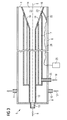
FIG 3 weist die Blaslanze 5 einen Außenmantel 8 auf. Der Außenmantel 8 ist in der Regel zylindrisch ausgebildet. Er erstreckt sich entlang einer Blaslanzenlängsachse 9, welche zugleich eine Zentralachse 9 (= Schwerpunktachse 9) der Blaslanze 5 darstellt. Die Blaslanze 5 erstreckt sich also entlang der Blaslanzenlängsachse 9. - Der Außenmantel 8 ist in der Regel wassergekühlt. Er weist zu diesem Zweck einen Zuführanschluss 10 und einen Abführanschluss 11 auf, über welche Kühlwasser 12 dem Außenmantel 8 zugeführt und - nach dem Durchströmen des Außenmantels 8 - wieder aus dem Außenmantel 8 abgeführt wird.
- Innerhalb des Außenmantels 8 verläuft eine Sauerstoffführung 13. Die Sauerstoffführung 13 weist am Ausblasende 4 einen Sauerstoff-Austritt 14 auf. Am Sauerstoff-Austritt 14 tritt der Sauerstoff 6 aus, welcher über einen Sauerstoff-Speiseanschluss 15 in die Sauerstoffführung 13 eingespeist wird.
- In der Regel verläuft die Sauerstoffführung 13 auf der Blaslanzenlängsachse 9. Weiterhin weist die Sauerstoffführung 13 in der Regel über einen Großteil der Länge der Blaslanze 5 einen gleich bleibenden Querschnitt auf. Am Ausblasende 4 weist die Sauerstoffführung 13 jedoch oftmals eine Aufweitung 16 auf. In diesem Bereich erweitert sich die Sauerstoffführung 13 kegelartig. Diese Ausgestaltungen, also die Anordnung der Sauerstoffführung 13 auf der Blaslanzenlängsachse 9 und das Vorhandensein der Aufweitung 16, sind jedoch nicht zwingend erforderlich.
- Innerhalb des Außenmantels 8 verläuft weiterhin eine Brenngasführung 17. Die Brenngasführung 17 weist am Ausblasende 4 eine Anzahl von Brenngas-Austritten 18 auf. An den Brenngas-Austritten 18 kann ein Brenngas 19 - beispielsweise Methan, Propan, Butan oder ein brennbares Prozessgas - austreten, welches an einem Brenngas-Speiseanschluss 20 in die Brenngasführung 17 eingespeist wird. Im Minimalfall ist nur ein einziger Brenngas-Austritt 18 vorhanden. In der Regel sind entweder mehrere Brenngas-Austritte 18 vorhanden oder der Brenngas-Austritt 18 ist als Ringspalt ausgebildet.
- Die Brenngas-Austritte 18 können am Ausblasende 4 neben dem Sauerstoff-Austritt 14 angeordnet sein. In der Regel sind die Brenngas-Austritte 18 jedoch in der Sauerstoffführung 13 angeordnet. Insbesondere kann mindestens einer der Brenngas-Austritte 18 entsprechend der Darstellung von
FIG 3 im Aufweitungsbereich 16 der Sauerstoffführung 13 angeordnet sein. - Der dem Sauerstoff-Austritt 14 zugeführte Sauerstoff 6 und das am Brenngas-Austritt 18 austretende Brenngas 19 mischen sich in einem Mischbereich 21 zu einem brennbaren und auch zündfähigen Gasgemisch. Der Mischbereich 21 kann entsprechend der Darstellung von
FIG 3 noch innerhalb der Sauerstoffführung 13 angeordnet sein. Insbesondere kann der Mischbereich 21 im Aufweitungsbereich 16 der Sauerstoffführung 13 angeordnet sein. Alternativ kann der Mischbereich 21 - insbesondere in dem Fall, dass die Brenngas-Austritte 18 nicht in der Sauerstoffführung 13 angeordnet sind - vor dem Ausblasende 4 der Blaslanze 5 liegen. - Das Gasgemisch wird mittels einer Zündeinrichtung 22 gezündet, die zu diesem Zweck in der Blaslanze 5 angeordnet ist. Die Zündeinrichtung 22 weist ihrerseits - siehe insbesondere
FIG 4 - eine Zündspitze 23 auf, mittels derer die zum Zünden des Gasgemisches erforderliche thermische Energie lokal generiert wird. Die Zündeinrichtung 22 ist insbesondere entsprechend der Darstellung vonFIG 3 innerhalb des Außenmantels 8 angeordnet. - Gemäß der in
FIG 4 dargestellten bevorzugten Ausgestaltung ist die Zündeinrichtung 22 als Zündlanze 22 ausgebildet, deren Zündspitze 23 Zündfunken 24 generiert. Die zum Generieren der Zündfunken 24 erforderlichen Spannungspulse werden von einem Zündgerät 25 bereitgestellt, das zu diesem Zweck mit der Zündlanze 22 verbunden ist. Die Verbindung zwischen der Zündlanze 22 und dem Zündgerät 25 kann starr sein. Vorzugsweise jedoch ist das Zündgerät 25 mit der Zündlanze 22 über ein Kabel 26 verbunden. - Das Zündgerät 25 ist vorzugsweise als kondensatorgespeiste Halbleiter-Zündeinrichtung ausgebildet. Der elektrische Aufbau ist aus
FIG 5 ersichtlich. - Gemäß
FIG 5 ist das Zündgerät 25 an eine Spannungsquelle U angeschlossen, beispielsweise das allgemeine Stromnetz mit - je nach Staat - einer Nennspannung von 100 V, 110 V oder 230 V und einer Netzfrequenz von 50 Hz oder 60 Hz. Die von der Spannungsquelle U abgegebene Spannung wird in einem Transformator 27 hochtransformiert und in einem Gleichrichter 28 gleichgerichtet. Falls die Spannungsquelle U eine Gleichspannung abgibt, ist dem Transformator 27 ein Wechselrichter vorgeordnet. - Die gleichgerichtete Spannung wird in einer Kondensatoreinheit 29 zwischengespeichert. Der Kondensatoreinheit 29 ist eine Halbleiter-Schalteinrichtung 30 nachgeordnet. Die Halbleiter-Schalteinrichtung 30 ihrerseits ist - direkt oder über das Kabel 26 - mit der Zündlanze 22 verbunden. Die Halbleiter-Schalteinrichtung 30 kann beispielsweise auf der Basis von GTO-Thyristoren (GTO = gate turn off) oder auf der Basis von IGBTs (= insulated gate bipolar transistor) realisiert sein.
- Bei geeigneter Wahl von Zündgerät 25 und Zündlanze 22 ist eine zuverlässige Generierung der Zündfunken 24 gewährleistet. Dies gilt sogar dann, wenn die Zündspitze 23 verschmutzt ist oder mit Öl oder Fett bedeckt ist. Geeignete Zündgeräte 25 und geeignete Zündlanzen 22 werden beispielsweise von der DURAG GmbH, Hamburg, Deutschland, vertrieben.
- Die vorliegende Erfindung wird nachfolgend in Verbindung mit einer als Zündlanze 22 ausgebildeten Zündeinrichtung 22 erläutert. Es sind jedoch ebenso entsprechende Ausgestaltungen möglich, bei denen die Zündeinrichtung 22 als Pilotbrenner ausgebildet ist.
- Die Zündlanze 22 kann zwischen einer ausgefahrenen Stellung und einer zurückgezogenen Stellung verfahren werden. In der ausgefahrenen Stellung wirkt die Zündspitze 23 mit den von ihr generierten Zündfunken 24 auf den Mischbereich 21. In dieser Stellung befindet sich die Zündlanze 22 zum Zünden des brennbaren Gasgemisches.
- In der zurückgezogenen Stellung ist die Zündlanze 22 in einen Schutzbereich 31 zurückgezogen, in dem die Zündlanze 22 vor Metall- und Schlackespritzern der Metallschmelze 1 geschützt ist. Gegebenenfalls kann der Schutzbereich 31 in dem Fall, dass die Zündlanze 22 sich in der zurückgezogenen Stellung befindet, zum Mischbereich 21 hin mittels einer feder- oder zwangsbetätigten Abdeckeinrichtung 32 abgedeckt sein. Die Zündlanze 22 wird nach dem Zünden des brennbaren Gasgemisches in die zurückgezogene Stellung überführt und verbleibt dort, bis ein erneutes Zünden des Gasgemisches erforderlich ist.
- Der Schutzbereich 31 kann nach Bedarf ausgebildet sein. Beispielsweise kann der Schutzbereich 31 gemäß
FIG 6 durch einen Führungskanal 33 gebildet sein, der an den Querschnitt der Zündlanze 22 angepasst ist. Es ist sogar möglich, dass der Schutzbereich 31 völlig offen ist. In diesem Fall kann sich der Schutz der Zündlanze 22 schlichtweg durch den (im Vergleich zur ausgefahrenen Stellung) größeren Abstand der Zündlanze 22 und insbesondere der Zündspitze 23 von der Metallschmelze 1 ergeben. - Nachfolgend werden in Verbindung mit den
FIG 6 bis 16 verschiedene Ausgestaltungen der erfindungsgemäßen Blaslanze 5 näher erläutert. - Die
FIG 6 bis 16 zeigen alle das Ausblasende 4 der Blaslanze 5. Insbesondere zeigen sie die Sauerstoffführung 13 einschließlich des Aufweitungsbereichs 16. Das Vorhandensein des Aufweitungsbereichs 16 ist stets bevorzugt. Es ist jedoch nur in Verbindung mit den Ausgestaltungen derFIG 8 bis 10 und12 zwingend erforderlich. - Die
FIG 6 bis 16 zeigen weiterhin alle die Brenngasführung 17 und die Brenngas-Austritte 18. Insbesondere zeigen sie mehrere Brenngas-Austritte 18. Dies ist jedoch nicht zwingend. Weiterhin zeigen sie, dass die Brenngas-Austritte 18 in der Sauerstoffführung 13 angeordnet sind, genauer gesagt am Anfang des Aufweitungsbereichs 16. Die Anordnung der Brenngas-Austritte 18 in der Sauerstoffführung 13 ist jedoch nur in Verbindung mit denFIG 10 bis 16 zwingend. - Die
FIG 6 bis 16 zeigen weiterhin alle den Führungskanal 33 und die - je nach FIG - vollständig oder teilweise im Führungskanal 33 angeordnete Zündlanze 22 einschließlich ihrer Zündspitze 23 und das Kabel 26. - Schließlich zeigen die
FIG 6 und 7 sowie 13 und 14 die Abdeckeinrichtung 32. Die Abdeckeinrichtung 32 könnte auch bei den Ausgestaltungen derFIG 8 bis 12 sowie 15 und 16 vorhanden sein. Alternativ könnte die Abdeckeinrichtung 32 auch bei denFIG 6 und 7 sowie 13 und 14 entfallen. - Gemäß den
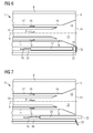
FIG 6 bis 9 erstreckt sich die Zündlanze 22 parallel zur Blaslanzenlängsachse 9. Die Zündlanze 22 ist parallel zur Blaslanzenlängsachse 9 verschiebbar. DieFIG 6 und8 zeigen die Zündlanze 22 in der zurückgezogenen Stellung, dieFIG 7 und9 zeigen die Zündlanze 22 in der ausgefahrenen Stellung. - Gemäß den
FIG 7 und9 ragt die Zündspitze 23 der Zündlanze 22 in der ausgefahrenen Stellung über das Ausblasende 4 der Blaslanze 5 hinaus. In der zurückgezogenen Stellung ist die gesamte Zündlanze 22 - also auch die Zündspitze 23 - gemäß denFIG 6 und8 hinter das Ausblasende 4 zurückgezogen. - Bei der Ausgestaltung der
FIG 6 und 7 ist die Zündlanze 22 neben der Sauerstoffführung 13 angeordnet. Alternativ kann die Sauerstoffführung 13 gemäß denFIG 8 und 9 den Aufweitungsbereich 16 aufweisen. In diesem Fall kann die Zündlanze 22 über den Aufweitungsbereich 16 vorgeschoben sein. - Falls entsprechend der Darstellung von
FIG 8 die Sauerstoffführung 13 den Aufweitungsbereich 16 aufweist, kann es weiterhin - im Gegensatz zuFIG 9 - ausreichend sein, wenn die Zündlanze 22 gemäßFIG 10 in der ausgefahrenen Stellung nur in den Aufweitungsbereich 16 hineinragt, aber nicht über das Ausblasende 4 hinausragt. - Wie obenstehend erläutert, sind die Brenngas-Austritte 18 - zumindest teilweise - in der Sauerstoffführung 13 angeordnet. Aufgrund dieser Ausgestaltung ist der Mischbereich 21 ebenfalls - zumindest teilweise - in der Sauerstoffführung 13 angeordnet. In diesem Fall kann es gemäß den
FIG 11 und12 ausreichen, dass der Führungskanal 33 eine seitliche Ausnehmung 34 aufweist, über welche der Führungskanal 33 zum Mischbereich 21 hin geöffnet ist. In diesem Fall kann es ausreichen, wenn die Zündspitze 23 der Zündlanze 22 in der ausgefahrenen Stellung der Zündlanze 22 im Bereich der seitlichen Ausnehmung 34 angeordnet ist. Besonders vorteilhaft ist es in diesem Zusammenhang, wenn die Zündspitze 23 entsprechend der Darstellung vonFIG 12 zur seitlichen Ausnehmung 34 hinzeigt. - Bei den obenstehend, in Verbindung mit den
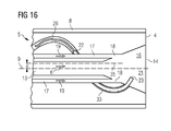
FIG 6 bis 12 erläuterten Ausgestaltungen ist die Zündlanze 22 gerade ("stabförmig"). Alternativ kann die Zündlanze 22 gemäß denFIG 13 bis 16 gebogen sein. Hierbei kann die Zündlanze 22 kreisbogenförmig ausgebildet sein. DieFIG 13 und14 zeigen eine entsprechende Zündlanze 22 in der eingefahrenen und der ausgefahrenen Stellung. Alternativ kann die Zündlanze 22 sich wendelartig (helixartig) um eine Zündeinrichtungslängsachse 35 herum erstrecken. Die Zündeinrichtungslängsachse 35 ist in diesem Fall parallel zur Blaslanzenlängsachse 9 angeordnet. Sie verläuft in einem konstanten Abstand (Offset) a zur Blaslanzenlängsachse 9. DieFIG 15 und16 zeigen eine entsprechende Zündlanze 22 in der eingefahrenen und der ausgefahrenen Stellung. - Gemäß den
FIG 14 und16 ragt die Zündspitze 23 der Zündlanze 22 in der ausgefahrenen Stellung in den Mischbereich 21 hinein. In der zurückgezogenen Stellung ist die Zündlanze 22 gemäß denFIG 13 und15 aus dem Mischbereich 21 zurückgezogen. Die vorliegende Erfindung weist viele Vorteile auf. Insbesondere ist auf einfache und zuverlässige Weise eine Zündung der (Haupt-)Flamme 7 der Blaslanze 5 möglich, wenn diese als Feuerlanze eingesetzt werden soll. Weiterhin entfallen im Falle einer direkten Zündung, also einer Ausbildung der Zündeinrichtung 22 als Zündlanze 22, Brenngas- und Sauerstoffführungen für den im Stand der Technik erforderlichen Pilotbrenner. Auch Steuereinrichtungen für den Pilotbrenner sind in diesem Fall nicht mehr erforderlich. - Obwohl die Erfindung im Detail durch das bevorzugte Ausführungsbeispiel näher illustriert und beschrieben wurde, so ist die Erfindung nicht durch die offenbarten Beispiele eingeschränkt und andere Varianten können vom Fachmann hieraus abgeleitet werden, ohne den Schutzumfang der Erfindung zu verlassen.
Claims (13)
- Blaslanze für eine Metallschmelzen-Vakuumbehandlungsanlage,- wobei die Blaslanze einen Außenmantel (8) aufweist, der sich entlang einer Blaslanzenlängsachse (9) erstreckt,- wobei innerhalb des Außenmantels (8) eine Sauerstoffführung (13) verläuft, die an einem Ausblasende (4) der Blaslanze einen Sauerstoff-Austritt (14) zum Austreten von Sauerstoff (6) aufweist, welcher über einen Sauerstoff-Speiseanschluss (15) in die Sauerstoffführung (13) eingespeist wird,- wobei innerhalb des Außenmantels (8) eine Brenngasführung (17) verläuft, die am Ausblasende (4) der Blaslanze eine Anzahl an Brenngas-Austritten (18) zum Austreten eines Brenngases (19) aufweist, welches über einen Brenngas-Speiseanschluss (20) in die Brenngasführung (17) eingespeist wird,- wobei in der Blaslanze eine Zündeinrichtung (22) angeordnet ist, die eine Zündspitze (23) zum Zünden eines brennbaren Gasgemisches aufweist,- wobei die Zündeinrichtung (22) zwischen einer ausgefahrenen Stellung und einer zurückgezogenen Stellung verfahrbar ist,- wobei die Zündspitze (23) in der ausgefahrenen Stellung auf einen Mischbereich (21) wirkt, in dem sich der dem Sauerstoff-Austritt (14) zugeführte Sauerstoff (6) und das an den Brenngas-Austritten (18) austretende Brenngas (19) zu dem brennbaren Gasgemisch mischen,- wobei die Zündeinrichtung (22) in der zurückgezogenen Stellung in einen Schutzbereich (31) zurückgezogen ist, in dem die Zündeinrichtung (22) vor Spritzern der Metallschmelze (1) geschützt ist.
- Blaslanze nach Anspruch 1,
dadurch gekennzeichnet, dass die Zündeinrichtung (22) sich parallel zur Blaslanzenlängsachse (9) erstreckt und dass die Zündeinrichtung (22) parallel zur Blaslanzenlängsachse (9) verschiebbar ist. - Blaslanze nach Anspruch 2,
dadurch gekennzeichnet, dass die Zündspitze (23) der Zündeinrichtung (22) in der ausgefahrenen Stellung über das Ausblasende (4) der Blaslanze hinausragt und in der zurückgezogenen Stellung hinter das Ausblasende (4) der Blaslanze zurückgezogen ist. - Blaslanze nach Anspruch 3,
dadurch gekennzeichnet, dass die Zündeinrichtung (22) neben der Sauerstoffführung (13) angeordnet ist. - Blaslanze nach Anspruch 2 oder 3,
dadurch gekennzeichnet, dass die Sauerstoffführung (13) am Ausblasende (4) einen Aufweitungsbereich (16) aufweist und dass die Zündeinrichtung (22) in der ausgefahrenen Stellung in den Aufweitungsbereich (16) hineinragt. - Blaslanze nach Anspruch 2,
dadurch gekennzeichnet, dass mindestens einer der Brenngas-Austritte (18) in der Sauerstoffführung (13) angeordnet ist, so dass der Mischbereich (21) noch innerhalb in der Sauerstoffführung (13) angeordnet ist, dass ein Führungskanal zum Führen der Zündeinrichtung (22) über eine seitliche Ausnehmung (34) zum Mischbereich (21) hin geöffnet ist und dass die Zündspitze (23) der Zündeinrichtung (22) in der ausgefahrenen Stellung im Bereich der Ausnehmung angeordnet ist. - Blaslanze nach Anspruch 1,
dadurch gekennzeichnet, dass die Zündeinrichtung (22) gebogen ist, dass die Zündspitze (23) der Zündeinrichtung (22) in der ausgefahrenen Stellung in den Mischbereich (21) hineinragt und in der zurückgezogenen Stellung aus dem Mischbereich (21) zurückgezogen ist. - Blaslanze nach Anspruch 7,
dadurch gekennzeichnet, dass die Zündeinrichtung (22) sich wendelartig um eine Zündeinrichtungslängsachse (35) herum erstreckt und dass die Zündeinrichtungslängsachse (35) parallel zur Blaslanzenlängsachse (9) in einem konstanten Abstand (a) zur Blaslanzenlängsachse (9) verläuft. - Blaslanze nach Anspruch 7,
dadurch gekennzeichnet, dass die Zündeinrichtung (22) kreisbogenförmig ausgebildet ist. - Blaslanze nach einem der obigen Ansprüche,
dadurch gekennzeichnet, dass die Zündeinrichtung (22) als Zündlanze (22) ausgebildet ist, deren Zündspitze (23) Zündfunken (24) generiert, und dass mit der Zündlanze (22) ein Zündgerät (25) zum Bereitstellen von für das Generieren der Zündfunken (24) erforderlichen Spannungspulsen verbunden ist. - Blaslanze nach Anspruch 10,
dadurch gekennzeichnet, dass das Zündgerät (25) als kondensatorgespeiste Halbleiter-Zündeinrichtung (30) ausgebildet ist. - Blaslanze nach Anspruch 10 oder 11,
dadurch gekennzeichnet, dass das Zündgerät (25) mit der Zündlanze (22) über ein Kabel (26) verbunden ist. - Blaslanze nach einem der obigen Ansprüche,
dadurch gekennzeichnet, dass der Schutzbereich (31) in der zurückgezogenen Stellung der Zündeinrichtung (22) zum Mischbereich (21) hin mittels einer Abdeckeinrichtung (32) abgedeckt ist.
Priority Applications (4)
| Application Number | Priority Date | Filing Date | Title |
|---|---|---|---|
| ES11184493.2T ES2566954T3 (es) | 2011-10-10 | 2011-10-10 | Lanza de soplado con encendido directo mediante lanza de encendido retráctil |
| EP11184493.2A EP2581462B1 (de) | 2011-10-10 | 2011-10-10 | Blaslanze mit Direktzündung durch zurückziehbare Zündlanze |
| RU2012140971A RU2607072C2 (ru) | 2011-10-10 | 2012-09-25 | Продувочная фурма с непосредственным розжигом посредством убирающейся запальной пики |
| MX2012011581A MX336531B (es) | 2011-10-10 | 2012-10-05 | Lanza de soplado con encendido directo mediante una lanza de encendido retractil. |
Applications Claiming Priority (1)
| Application Number | Priority Date | Filing Date | Title |
|---|---|---|---|
| EP11184493.2A EP2581462B1 (de) | 2011-10-10 | 2011-10-10 | Blaslanze mit Direktzündung durch zurückziehbare Zündlanze |
Publications (2)
| Publication Number | Publication Date |
|---|---|
| EP2581462A1 true EP2581462A1 (de) | 2013-04-17 |
| EP2581462B1 EP2581462B1 (de) | 2016-03-02 |
Family
ID=44759562
Family Applications (1)
| Application Number | Title | Priority Date | Filing Date |
|---|---|---|---|
| EP11184493.2A Active EP2581462B1 (de) | 2011-10-10 | 2011-10-10 | Blaslanze mit Direktzündung durch zurückziehbare Zündlanze |
Country Status (4)
| Country | Link |
|---|---|
| EP (1) | EP2581462B1 (de) |
| ES (1) | ES2566954T3 (de) |
| MX (1) | MX336531B (de) |
| RU (1) | RU2607072C2 (de) |
Families Citing this family (1)
| Publication number | Priority date | Publication date | Assignee | Title |
|---|---|---|---|---|
| EP4692707A1 (de) * | 2024-08-05 | 2026-02-11 | Refractory Intellectual Property GmbH & Co. KG | Lanzensystem und verfahren zum betreiben einer sauerstofflanze |
Citations (6)
| Publication number | Priority date | Publication date | Assignee | Title |
|---|---|---|---|---|
| US3486498A (en) * | 1966-10-06 | 1969-12-30 | Felix Taschler | Method and device for ignition outflowing gas for the production of heating flames |
| US3599949A (en) * | 1967-02-23 | 1971-08-17 | Steel Co Of Wales Ltd | Manufacture of steel |
| EP0363787A1 (de) * | 1988-10-12 | 1990-04-18 | Deutsche Babcock Energie- und Umwelttechnik Aktiengesellschaft | Brenner mit elektrischer Zündeinrichtung für gasförmige Brennstoffe und Sauerstoff |
| DE19932178A1 (de) * | 1998-07-10 | 2000-01-13 | Elti Srl | Hochgeschwindigkeitsbrenner für Öfen zur Stahlerzeugung |
| EP1054069A2 (de) * | 1999-05-21 | 2000-11-22 | Kawasaki Steel Corporation | Multifunktionelle Lanze für eine Vakuumkammer zur Entgasung sowie Verwendungsverfahren |
| DE102010007119B3 (de) | 2010-02-05 | 2011-07-28 | Technometal GmbH, 47058 | Vakuumumlaufentgasungsanlage mit Zündbrenner |
Family Cites Families (3)
| Publication number | Priority date | Publication date | Assignee | Title |
|---|---|---|---|---|
| DE4442362C1 (de) * | 1994-11-18 | 1996-04-18 | Mannesmann Ag | Verfahren und Vorrichtung zum Behandeln von einer in einem metallurgischen Gefäß befindlichen Metallschmelze |
| RU2142096C1 (ru) * | 1998-01-14 | 1999-11-27 | ОО "ПКФ" Автодорстрой" | Комбинированная горелка |
| DE19817590C1 (de) * | 1998-04-20 | 1999-03-18 | Technometal Ges Fuer Metalltec | Variabel einsetzbare Kombilanze |
-
2011
- 2011-10-10 ES ES11184493.2T patent/ES2566954T3/es active Active
- 2011-10-10 EP EP11184493.2A patent/EP2581462B1/de active Active
-
2012
- 2012-09-25 RU RU2012140971A patent/RU2607072C2/ru active
- 2012-10-05 MX MX2012011581A patent/MX336531B/es unknown
Patent Citations (7)
| Publication number | Priority date | Publication date | Assignee | Title |
|---|---|---|---|---|
| US3486498A (en) * | 1966-10-06 | 1969-12-30 | Felix Taschler | Method and device for ignition outflowing gas for the production of heating flames |
| US3599949A (en) * | 1967-02-23 | 1971-08-17 | Steel Co Of Wales Ltd | Manufacture of steel |
| EP0363787A1 (de) * | 1988-10-12 | 1990-04-18 | Deutsche Babcock Energie- und Umwelttechnik Aktiengesellschaft | Brenner mit elektrischer Zündeinrichtung für gasförmige Brennstoffe und Sauerstoff |
| DE19932178A1 (de) * | 1998-07-10 | 2000-01-13 | Elti Srl | Hochgeschwindigkeitsbrenner für Öfen zur Stahlerzeugung |
| EP1054069A2 (de) * | 1999-05-21 | 2000-11-22 | Kawasaki Steel Corporation | Multifunktionelle Lanze für eine Vakuumkammer zur Entgasung sowie Verwendungsverfahren |
| DE102010007119B3 (de) | 2010-02-05 | 2011-07-28 | Technometal GmbH, 47058 | Vakuumumlaufentgasungsanlage mit Zündbrenner |
| EP2354259A1 (de) * | 2010-02-05 | 2011-08-10 | Technometal GmbH | Vakuumumlaufentgasungsanlage mit Zündbrenner |
Also Published As
| Publication number | Publication date |
|---|---|
| RU2012140971A (ru) | 2014-03-27 |
| MX336531B (es) | 2016-01-21 |
| MX2012011581A (es) | 2013-10-15 |
| EP2581462B1 (de) | 2016-03-02 |
| ES2566954T3 (es) | 2016-04-18 |
| RU2607072C2 (ru) | 2017-01-10 |
Similar Documents
| Publication | Publication Date | Title |
|---|---|---|
| EP2181287B1 (de) | Kohlenstaubkombinationsbrenner mit integriertem pilotbrenner | |
| EP2313687B1 (de) | Verfahren zum zünden und zum betrieb von brennern bei der vergasung kohlenstoffhaltiger brennstoffe | |
| EP3177743B1 (de) | Brenner-lanzen-einheit | |
| EP2290310A1 (de) | Verfahren zur dynamischen Regelung zumindest einer Einheit umfassend mindestens einen Brenner sowie Vorrichtung zur Durchführung des Verfahrens | |
| DE102014201386A1 (de) | Pilotbrenner als Bestandteil einer Brenneranordnung für die Druckvergasung fester und flüssiger Brennstoffe | |
| EP2581462B1 (de) | Blaslanze mit Direktzündung durch zurückziehbare Zündlanze | |
| EP2054669A1 (de) | Brenner mit einem schutzelement für zündelektroden | |
| EP2846091A1 (de) | Oxy-gas burner with incandescent ignition | |
| EP3170366B1 (de) | Elektrischer lichtbogenofen mit einer sicherheitsvorrichtung und verfahren zur sicherung von peripheriegeräten an elektrischen lichtbogenöfen | |
| DE1919247C3 (de) | Vorrichtung zum Zünden eines dem Hilfsbrenner einer Abfackelvorrichtung zuströmenden brennbaren Gas-Luft-Gemisches | |
| EP0249790A2 (de) | Vorrichtung zum thermischen Spritzen von Auftragsschweisswerkstoffen | |
| DE60209146T2 (de) | Elektrode, insbesondere für elektrolichtbogenöfen der stahlindustrie und dergleichen, und entsprechende operationsmethode | |
| EP2853610B1 (de) | Vorrichtung und Verfahren zum Elektroschlacke-Umschmelzen | |
| DE2537352A1 (de) | Seitlich befeuerte heizanlage | |
| DE1451610B2 (de) | Vorri chtung zum Zünden und überwachen der Flammen eines Zündbrenners und eines Hauptbrenners | |
| EP2912199B1 (de) | Verfahren und vorrichtung zur energiezufuhr in ein schrotthaufwerk in einem elektrolichtbogenofen | |
| EP0108923A1 (de) | Zündeinrichtung für Kohlenstaubfeuerungen | |
| EP2527734A1 (de) | Industriebrenner mit geringer NOX-Emission | |
| DE3130972A1 (de) | "verfahren zum vorwaermen und aufheizen von leeren aod-konvertern" | |
| DE3050694C2 (de) | Einrichtung zum Gasstrahlschneiden von Materialien | |
| EP2626628B1 (de) | Befeuerung eines Industrieofens und zugehöriger Brenner | |
| EP3517509A1 (de) | Vorrichtung und verfahren zum beheizen und transportieren einer glasschmelze | |
| DE102018208433A1 (de) | Sauerstoffinjektor für einen Konverter insbesondere zur Stahlherstellung | |
| DE19922509A1 (de) | Vorrichtung und Verfahren zur Eindüsung von Erdgas und/oder Sauerstoff | |
| EP3293456A1 (de) | Brenner |
Legal Events
| Date | Code | Title | Description |
|---|---|---|---|
| PUAI | Public reference made under article 153(3) epc to a published international application that has entered the european phase |
Free format text: ORIGINAL CODE: 0009012 |
|
| AK | Designated contracting states |
Kind code of ref document: A1 Designated state(s): AL AT BE BG CH CY CZ DE DK EE ES FI FR GB GR HR HU IE IS IT LI LT LU LV MC MK MT NL NO PL PT RO RS SE SI SK SM TR |
|
| AX | Request for extension of the european patent |
Extension state: BA ME |
|
| 17P | Request for examination filed |
Effective date: 20131014 |
|
| RBV | Designated contracting states (corrected) |
Designated state(s): AL AT BE BG CH CY CZ DE DK EE ES FI FR GB GR HR HU IE IS IT LI LT LU LV MC MK MT NL NO PL PT RO RS SE SI SK SM TR |
|
| 17Q | First examination report despatched |
Effective date: 20131112 |
|
| RAP1 | Party data changed (applicant data changed or rights of an application transferred) |
Owner name: PRIMETALS TECHNOLOGIES GERMANY GMBH |
|
| GRAP | Despatch of communication of intention to grant a patent |
Free format text: ORIGINAL CODE: EPIDOSNIGR1 |
|
| INTG | Intention to grant announced |
Effective date: 20150924 |
|
| GRAS | Grant fee paid |
Free format text: ORIGINAL CODE: EPIDOSNIGR3 |
|
| GRAA | (expected) grant |
Free format text: ORIGINAL CODE: 0009210 |
|
| AK | Designated contracting states |
Kind code of ref document: B1 Designated state(s): AL AT BE BG CH CY CZ DE DK EE ES FI FR GB GR HR HU IE IS IT LI LT LU LV MC MK MT NL NO PL PT RO RS SE SI SK SM TR |
|
| REG | Reference to a national code |
Ref country code: GB Ref legal event code: FG4D Free format text: NOT ENGLISH |
|
| REG | Reference to a national code |
Ref country code: AT Ref legal event code: REF Ref document number: 778104 Country of ref document: AT Kind code of ref document: T Effective date: 20160315 Ref country code: CH Ref legal event code: EP |
|
| REG | Reference to a national code |
Ref country code: IE Ref legal event code: FG4D Free format text: LANGUAGE OF EP DOCUMENT: GERMAN |
|
| REG | Reference to a national code |
Ref country code: DE Ref legal event code: R096 Ref document number: 502011008968 Country of ref document: DE |
|
| REG | Reference to a national code |
Ref country code: ES Ref legal event code: FG2A Ref document number: 2566954 Country of ref document: ES Kind code of ref document: T3 Effective date: 20160418 |
|
| REG | Reference to a national code |
Ref country code: NL Ref legal event code: MP Effective date: 20160302 |
|
| REG | Reference to a national code |
Ref country code: LT Ref legal event code: MG4D |
|
| PG25 | Lapsed in a contracting state [announced via postgrant information from national office to epo] |
Ref country code: GR Free format text: LAPSE BECAUSE OF FAILURE TO SUBMIT A TRANSLATION OF THE DESCRIPTION OR TO PAY THE FEE WITHIN THE PRESCRIBED TIME-LIMIT Effective date: 20160603 Ref country code: HR Free format text: LAPSE BECAUSE OF FAILURE TO SUBMIT A TRANSLATION OF THE DESCRIPTION OR TO PAY THE FEE WITHIN THE PRESCRIBED TIME-LIMIT Effective date: 20160302 Ref country code: NO Free format text: LAPSE BECAUSE OF FAILURE TO SUBMIT A TRANSLATION OF THE DESCRIPTION OR TO PAY THE FEE WITHIN THE PRESCRIBED TIME-LIMIT Effective date: 20160602 Ref country code: FI Free format text: LAPSE BECAUSE OF FAILURE TO SUBMIT A TRANSLATION OF THE DESCRIPTION OR TO PAY THE FEE WITHIN THE PRESCRIBED TIME-LIMIT Effective date: 20160302 |
|
| PG25 | Lapsed in a contracting state [announced via postgrant information from national office to epo] |
Ref country code: SE Free format text: LAPSE BECAUSE OF FAILURE TO SUBMIT A TRANSLATION OF THE DESCRIPTION OR TO PAY THE FEE WITHIN THE PRESCRIBED TIME-LIMIT Effective date: 20160302 Ref country code: RS Free format text: LAPSE BECAUSE OF FAILURE TO SUBMIT A TRANSLATION OF THE DESCRIPTION OR TO PAY THE FEE WITHIN THE PRESCRIBED TIME-LIMIT Effective date: 20160302 Ref country code: NL Free format text: LAPSE BECAUSE OF FAILURE TO SUBMIT A TRANSLATION OF THE DESCRIPTION OR TO PAY THE FEE WITHIN THE PRESCRIBED TIME-LIMIT Effective date: 20160302 Ref country code: LV Free format text: LAPSE BECAUSE OF FAILURE TO SUBMIT A TRANSLATION OF THE DESCRIPTION OR TO PAY THE FEE WITHIN THE PRESCRIBED TIME-LIMIT Effective date: 20160302 Ref country code: LT Free format text: LAPSE BECAUSE OF FAILURE TO SUBMIT A TRANSLATION OF THE DESCRIPTION OR TO PAY THE FEE WITHIN THE PRESCRIBED TIME-LIMIT Effective date: 20160302 Ref country code: PL Free format text: LAPSE BECAUSE OF FAILURE TO SUBMIT A TRANSLATION OF THE DESCRIPTION OR TO PAY THE FEE WITHIN THE PRESCRIBED TIME-LIMIT Effective date: 20160302 |
|
| PG25 | Lapsed in a contracting state [announced via postgrant information from national office to epo] |
Ref country code: IS Free format text: LAPSE BECAUSE OF FAILURE TO SUBMIT A TRANSLATION OF THE DESCRIPTION OR TO PAY THE FEE WITHIN THE PRESCRIBED TIME-LIMIT Effective date: 20160702 Ref country code: EE Free format text: LAPSE BECAUSE OF FAILURE TO SUBMIT A TRANSLATION OF THE DESCRIPTION OR TO PAY THE FEE WITHIN THE PRESCRIBED TIME-LIMIT Effective date: 20160302 |
|
| PG25 | Lapsed in a contracting state [announced via postgrant information from national office to epo] |
Ref country code: RO Free format text: LAPSE BECAUSE OF FAILURE TO SUBMIT A TRANSLATION OF THE DESCRIPTION OR TO PAY THE FEE WITHIN THE PRESCRIBED TIME-LIMIT Effective date: 20160302 Ref country code: SK Free format text: LAPSE BECAUSE OF FAILURE TO SUBMIT A TRANSLATION OF THE DESCRIPTION OR TO PAY THE FEE WITHIN THE PRESCRIBED TIME-LIMIT Effective date: 20160302 Ref country code: PT Free format text: LAPSE BECAUSE OF FAILURE TO SUBMIT A TRANSLATION OF THE DESCRIPTION OR TO PAY THE FEE WITHIN THE PRESCRIBED TIME-LIMIT Effective date: 20160704 Ref country code: CZ Free format text: LAPSE BECAUSE OF FAILURE TO SUBMIT A TRANSLATION OF THE DESCRIPTION OR TO PAY THE FEE WITHIN THE PRESCRIBED TIME-LIMIT Effective date: 20160302 Ref country code: SM Free format text: LAPSE BECAUSE OF FAILURE TO SUBMIT A TRANSLATION OF THE DESCRIPTION OR TO PAY THE FEE WITHIN THE PRESCRIBED TIME-LIMIT Effective date: 20160302 |
|
| REG | Reference to a national code |
Ref country code: DE Ref legal event code: R097 Ref document number: 502011008968 Country of ref document: DE |
|
| PLBE | No opposition filed within time limit |
Free format text: ORIGINAL CODE: 0009261 |
|
| STAA | Information on the status of an ep patent application or granted ep patent |
Free format text: STATUS: NO OPPOSITION FILED WITHIN TIME LIMIT |
|
| PG25 | Lapsed in a contracting state [announced via postgrant information from national office to epo] |
Ref country code: DK Free format text: LAPSE BECAUSE OF FAILURE TO SUBMIT A TRANSLATION OF THE DESCRIPTION OR TO PAY THE FEE WITHIN THE PRESCRIBED TIME-LIMIT Effective date: 20160302 |
|
| 26N | No opposition filed |
Effective date: 20161205 |
|
| PG25 | Lapsed in a contracting state [announced via postgrant information from national office to epo] |
Ref country code: SI Free format text: LAPSE BECAUSE OF FAILURE TO SUBMIT A TRANSLATION OF THE DESCRIPTION OR TO PAY THE FEE WITHIN THE PRESCRIBED TIME-LIMIT Effective date: 20160302 Ref country code: BG Free format text: LAPSE BECAUSE OF FAILURE TO SUBMIT A TRANSLATION OF THE DESCRIPTION OR TO PAY THE FEE WITHIN THE PRESCRIBED TIME-LIMIT Effective date: 20160602 |
|
| REG | Reference to a national code |
Ref country code: CH Ref legal event code: PL |
|
| GBPC | Gb: european patent ceased through non-payment of renewal fee |
Effective date: 20161010 |
|
| REG | Reference to a national code |
Ref country code: IE Ref legal event code: MM4A |
|
| REG | Reference to a national code |
Ref country code: FR Ref legal event code: ST Effective date: 20170630 |
|
| PG25 | Lapsed in a contracting state [announced via postgrant information from national office to epo] |
Ref country code: FR Free format text: LAPSE BECAUSE OF NON-PAYMENT OF DUE FEES Effective date: 20161102 Ref country code: GB Free format text: LAPSE BECAUSE OF NON-PAYMENT OF DUE FEES Effective date: 20161010 Ref country code: CH Free format text: LAPSE BECAUSE OF NON-PAYMENT OF DUE FEES Effective date: 20161031 Ref country code: LI Free format text: LAPSE BECAUSE OF NON-PAYMENT OF DUE FEES Effective date: 20161031 |
|
| PG25 | Lapsed in a contracting state [announced via postgrant information from national office to epo] |
Ref country code: LU Free format text: LAPSE BECAUSE OF NON-PAYMENT OF DUE FEES Effective date: 20161010 |
|
| PG25 | Lapsed in a contracting state [announced via postgrant information from national office to epo] |
Ref country code: IE Free format text: LAPSE BECAUSE OF NON-PAYMENT OF DUE FEES Effective date: 20161010 |
|
| REG | Reference to a national code |
Ref country code: AT Ref legal event code: MM01 Ref document number: 778104 Country of ref document: AT Kind code of ref document: T Effective date: 20161010 |
|
| PG25 | Lapsed in a contracting state [announced via postgrant information from national office to epo] |
Ref country code: AT Free format text: LAPSE BECAUSE OF NON-PAYMENT OF DUE FEES Effective date: 20161010 |
|
| PG25 | Lapsed in a contracting state [announced via postgrant information from national office to epo] |
Ref country code: HU Free format text: LAPSE BECAUSE OF FAILURE TO SUBMIT A TRANSLATION OF THE DESCRIPTION OR TO PAY THE FEE WITHIN THE PRESCRIBED TIME-LIMIT; INVALID AB INITIO Effective date: 20111010 Ref country code: CY Free format text: LAPSE BECAUSE OF FAILURE TO SUBMIT A TRANSLATION OF THE DESCRIPTION OR TO PAY THE FEE WITHIN THE PRESCRIBED TIME-LIMIT Effective date: 20160302 |
|
| PG25 | Lapsed in a contracting state [announced via postgrant information from national office to epo] |
Ref country code: TR Free format text: LAPSE BECAUSE OF FAILURE TO SUBMIT A TRANSLATION OF THE DESCRIPTION OR TO PAY THE FEE WITHIN THE PRESCRIBED TIME-LIMIT Effective date: 20160302 Ref country code: MT Free format text: LAPSE BECAUSE OF FAILURE TO SUBMIT A TRANSLATION OF THE DESCRIPTION OR TO PAY THE FEE WITHIN THE PRESCRIBED TIME-LIMIT Effective date: 20160302 Ref country code: MC Free format text: LAPSE BECAUSE OF FAILURE TO SUBMIT A TRANSLATION OF THE DESCRIPTION OR TO PAY THE FEE WITHIN THE PRESCRIBED TIME-LIMIT Effective date: 20160302 Ref country code: MK Free format text: LAPSE BECAUSE OF FAILURE TO SUBMIT A TRANSLATION OF THE DESCRIPTION OR TO PAY THE FEE WITHIN THE PRESCRIBED TIME-LIMIT Effective date: 20160302 |
|
| PG25 | Lapsed in a contracting state [announced via postgrant information from national office to epo] |
Ref country code: AL Free format text: LAPSE BECAUSE OF FAILURE TO SUBMIT A TRANSLATION OF THE DESCRIPTION OR TO PAY THE FEE WITHIN THE PRESCRIBED TIME-LIMIT Effective date: 20160302 |
|
| REG | Reference to a national code |
Ref country code: DE Ref legal event code: R081 Ref document number: 502011008968 Country of ref document: DE Owner name: PRIMETALS TECHNOLOGIES GERMANY GMBH, DE Free format text: FORMER OWNER: PRIMETALS TECHNOLOGIES GERMANY GMBH, 91052 ERLANGEN, DE |
|
| PGFP | Annual fee paid to national office [announced via postgrant information from national office to epo] |
Ref country code: DE Payment date: 20251021 Year of fee payment: 15 |
|
| PGFP | Annual fee paid to national office [announced via postgrant information from national office to epo] |
Ref country code: IT Payment date: 20251024 Year of fee payment: 15 |
|
| PGFP | Annual fee paid to national office [announced via postgrant information from national office to epo] |
Ref country code: BE Payment date: 20251021 Year of fee payment: 15 |
|
| PGFP | Annual fee paid to national office [announced via postgrant information from national office to epo] |
Ref country code: ES Payment date: 20251210 Year of fee payment: 15 |