EP2580408B1 - Turm mit einem adapterstück sowie verfahren zur herstellung eines turms mit einem adapterstück - Google Patents
Turm mit einem adapterstück sowie verfahren zur herstellung eines turms mit einem adapterstück Download PDFInfo
- Publication number
- EP2580408B1 EP2580408B1 EP11719508.1A EP11719508A EP2580408B1 EP 2580408 B1 EP2580408 B1 EP 2580408B1 EP 11719508 A EP11719508 A EP 11719508A EP 2580408 B1 EP2580408 B1 EP 2580408B1
- Authority
- EP
- European Patent Office
- Prior art keywords
- concrete
- tower
- steel
- adapter piece
- flange
- Prior art date
- Legal status (The legal status is an assumption and is not a legal conclusion. Google has not performed a legal analysis and makes no representation as to the accuracy of the status listed.)
- Active
Links
Images


Classifications
-
- E—FIXED CONSTRUCTIONS
- E04—BUILDING
- E04H—BUILDINGS OR LIKE STRUCTURES FOR PARTICULAR PURPOSES; SWIMMING OR SPLASH BATHS OR POOLS; MASTS; FENCING; TENTS OR CANOPIES, IN GENERAL
- E04H12/00—Towers; Masts or poles; Chimney stacks; Water-towers; Methods of erecting such structures
- E04H12/02—Structures made of specified materials
- E04H12/08—Structures made of specified materials of metal
- E04H12/085—Details of flanges for tubular masts
-
- B—PERFORMING OPERATIONS; TRANSPORTING
- B24—GRINDING; POLISHING
- B24B—MACHINES, DEVICES, OR PROCESSES FOR GRINDING OR POLISHING; DRESSING OR CONDITIONING OF ABRADING SURFACES; FEEDING OF GRINDING, POLISHING, OR LAPPING AGENTS
- B24B7/00—Machines or devices designed for grinding plane surfaces on work, including polishing plane glass surfaces; Accessories therefor
- B24B7/10—Single-purpose machines or devices
- B24B7/16—Single-purpose machines or devices for grinding end-faces, e.g. of gauges, rollers, nuts, piston rings
-
- B—PERFORMING OPERATIONS; TRANSPORTING
- B24—GRINDING; POLISHING
- B24B—MACHINES, DEVICES, OR PROCESSES FOR GRINDING OR POLISHING; DRESSING OR CONDITIONING OF ABRADING SURFACES; FEEDING OF GRINDING, POLISHING, OR LAPPING AGENTS
- B24B27/00—Other grinding machines or devices
- B24B27/0069—Other grinding machines or devices with means for feeding the work-pieces to the grinding tool, e.g. turntables, transfer means
-
- B—PERFORMING OPERATIONS; TRANSPORTING
- B24—GRINDING; POLISHING
- B24B—MACHINES, DEVICES, OR PROCESSES FOR GRINDING OR POLISHING; DRESSING OR CONDITIONING OF ABRADING SURFACES; FEEDING OF GRINDING, POLISHING, OR LAPPING AGENTS
- B24B7/00—Machines or devices designed for grinding plane surfaces on work, including polishing plane glass surfaces; Accessories therefor
- B24B7/20—Machines or devices designed for grinding plane surfaces on work, including polishing plane glass surfaces; Accessories therefor characterised by a special design with respect to properties of the material of non-metallic articles to be ground
- B24B7/22—Machines or devices designed for grinding plane surfaces on work, including polishing plane glass surfaces; Accessories therefor characterised by a special design with respect to properties of the material of non-metallic articles to be ground for grinding inorganic material, e.g. stone, ceramics, porcelain
-
- E—FIXED CONSTRUCTIONS
- E04—BUILDING
- E04H—BUILDINGS OR LIKE STRUCTURES FOR PARTICULAR PURPOSES; SWIMMING OR SPLASH BATHS OR POOLS; MASTS; FENCING; TENTS OR CANOPIES, IN GENERAL
- E04H12/00—Towers; Masts or poles; Chimney stacks; Water-towers; Methods of erecting such structures
- E04H12/02—Structures made of specified materials
- E04H12/08—Structures made of specified materials of metal
-
- E—FIXED CONSTRUCTIONS
- E04—BUILDING
- E04H—BUILDINGS OR LIKE STRUCTURES FOR PARTICULAR PURPOSES; SWIMMING OR SPLASH BATHS OR POOLS; MASTS; FENCING; TENTS OR CANOPIES, IN GENERAL
- E04H12/00—Towers; Masts or poles; Chimney stacks; Water-towers; Methods of erecting such structures
- E04H12/02—Structures made of specified materials
- E04H12/12—Structures made of specified materials of concrete or other stone-like material, with or without internal or external reinforcements, e.g. with metal coverings, with permanent form elements
-
- E—FIXED CONSTRUCTIONS
- E04—BUILDING
- E04H—BUILDINGS OR LIKE STRUCTURES FOR PARTICULAR PURPOSES; SWIMMING OR SPLASH BATHS OR POOLS; MASTS; FENCING; TENTS OR CANOPIES, IN GENERAL
- E04H12/00—Towers; Masts or poles; Chimney stacks; Water-towers; Methods of erecting such structures
- E04H12/16—Prestressed structures
-
- F—MECHANICAL ENGINEERING; LIGHTING; HEATING; WEAPONS; BLASTING
- F03—MACHINES OR ENGINES FOR LIQUIDS; WIND, SPRING, OR WEIGHT MOTORS; PRODUCING MECHANICAL POWER OR A REACTIVE PROPULSIVE THRUST, NOT OTHERWISE PROVIDED FOR
- F03D—WIND MOTORS
- F03D13/00—Assembly, mounting or commissioning of wind motors; Arrangements specially adapted for transporting wind motor components
- F03D13/10—Assembly of wind motors; Arrangements for erecting wind motors
-
- F—MECHANICAL ENGINEERING; LIGHTING; HEATING; WEAPONS; BLASTING
- F03—MACHINES OR ENGINES FOR LIQUIDS; WIND, SPRING, OR WEIGHT MOTORS; PRODUCING MECHANICAL POWER OR A REACTIVE PROPULSIVE THRUST, NOT OTHERWISE PROVIDED FOR
- F03D—WIND MOTORS
- F03D13/00—Assembly, mounting or commissioning of wind motors; Arrangements specially adapted for transporting wind motor components
- F03D13/20—Arrangements for mounting or supporting wind motors; Masts or towers for wind motors
-
- F—MECHANICAL ENGINEERING; LIGHTING; HEATING; WEAPONS; BLASTING
- F05—INDEXING SCHEMES RELATING TO ENGINES OR PUMPS IN VARIOUS SUBCLASSES OF CLASSES F01-F04
- F05B—INDEXING SCHEME RELATING TO WIND, SPRING, WEIGHT, INERTIA OR LIKE MOTORS, TO MACHINES OR ENGINES FOR LIQUIDS COVERED BY SUBCLASSES F03B, F03D AND F03G
- F05B2230/00—Manufacture
- F05B2230/10—Manufacture by removing material
-
- F—MECHANICAL ENGINEERING; LIGHTING; HEATING; WEAPONS; BLASTING
- F05—INDEXING SCHEMES RELATING TO ENGINES OR PUMPS IN VARIOUS SUBCLASSES OF CLASSES F01-F04
- F05B—INDEXING SCHEME RELATING TO WIND, SPRING, WEIGHT, INERTIA OR LIKE MOTORS, TO MACHINES OR ENGINES FOR LIQUIDS COVERED BY SUBCLASSES F03B, F03D AND F03G
- F05B2230/00—Manufacture
- F05B2230/60—Assembly methods
-
- F—MECHANICAL ENGINEERING; LIGHTING; HEATING; WEAPONS; BLASTING
- F05—INDEXING SCHEMES RELATING TO ENGINES OR PUMPS IN VARIOUS SUBCLASSES OF CLASSES F01-F04
- F05B—INDEXING SCHEME RELATING TO WIND, SPRING, WEIGHT, INERTIA OR LIKE MOTORS, TO MACHINES OR ENGINES FOR LIQUIDS COVERED BY SUBCLASSES F03B, F03D AND F03G
- F05B2240/00—Components
- F05B2240/90—Mounting on supporting structures or systems
- F05B2240/91—Mounting on supporting structures or systems on a stationary structure
- F05B2240/912—Mounting on supporting structures or systems on a stationary structure on a tower
-
- F—MECHANICAL ENGINEERING; LIGHTING; HEATING; WEAPONS; BLASTING
- F05—INDEXING SCHEMES RELATING TO ENGINES OR PUMPS IN VARIOUS SUBCLASSES OF CLASSES F01-F04
- F05B—INDEXING SCHEME RELATING TO WIND, SPRING, WEIGHT, INERTIA OR LIKE MOTORS, TO MACHINES OR ENGINES FOR LIQUIDS COVERED BY SUBCLASSES F03B, F03D AND F03G
- F05B2250/00—Geometry
- F05B2250/10—Geometry two-dimensional
- F05B2250/14—Geometry two-dimensional elliptical
- F05B2250/141—Geometry two-dimensional elliptical circular
-
- F—MECHANICAL ENGINEERING; LIGHTING; HEATING; WEAPONS; BLASTING
- F05—INDEXING SCHEMES RELATING TO ENGINES OR PUMPS IN VARIOUS SUBCLASSES OF CLASSES F01-F04
- F05B—INDEXING SCHEME RELATING TO WIND, SPRING, WEIGHT, INERTIA OR LIKE MOTORS, TO MACHINES OR ENGINES FOR LIQUIDS COVERED BY SUBCLASSES F03B, F03D AND F03G
- F05B2250/00—Geometry
- F05B2250/20—Geometry three-dimensional
- F05B2250/23—Geometry three-dimensional prismatic
- F05B2250/231—Geometry three-dimensional prismatic cylindrical
-
- F—MECHANICAL ENGINEERING; LIGHTING; HEATING; WEAPONS; BLASTING
- F05—INDEXING SCHEMES RELATING TO ENGINES OR PUMPS IN VARIOUS SUBCLASSES OF CLASSES F01-F04
- F05B—INDEXING SCHEME RELATING TO WIND, SPRING, WEIGHT, INERTIA OR LIKE MOTORS, TO MACHINES OR ENGINES FOR LIQUIDS COVERED BY SUBCLASSES F03B, F03D AND F03G
- F05B2260/00—Function
- F05B2260/30—Retaining components in desired mutual position
- F05B2260/301—Retaining bolts or nuts
-
- F—MECHANICAL ENGINEERING; LIGHTING; HEATING; WEAPONS; BLASTING
- F05—INDEXING SCHEMES RELATING TO ENGINES OR PUMPS IN VARIOUS SUBCLASSES OF CLASSES F01-F04
- F05B—INDEXING SCHEME RELATING TO WIND, SPRING, WEIGHT, INERTIA OR LIKE MOTORS, TO MACHINES OR ENGINES FOR LIQUIDS COVERED BY SUBCLASSES F03B, F03D AND F03G
- F05B2270/00—Control
- F05B2270/30—Control parameters, e.g. input parameters
- F05B2270/305—Tolerances
-
- Y—GENERAL TAGGING OF NEW TECHNOLOGICAL DEVELOPMENTS; GENERAL TAGGING OF CROSS-SECTIONAL TECHNOLOGIES SPANNING OVER SEVERAL SECTIONS OF THE IPC; TECHNICAL SUBJECTS COVERED BY FORMER USPC CROSS-REFERENCE ART COLLECTIONS [XRACs] AND DIGESTS
- Y02—TECHNOLOGIES OR APPLICATIONS FOR MITIGATION OR ADAPTATION AGAINST CLIMATE CHANGE
- Y02E—REDUCTION OF GREENHOUSE GAS [GHG] EMISSIONS, RELATED TO ENERGY GENERATION, TRANSMISSION OR DISTRIBUTION
- Y02E10/00—Energy generation through renewable energy sources
- Y02E10/70—Wind energy
- Y02E10/72—Wind turbines with rotation axis in wind direction
-
- Y—GENERAL TAGGING OF NEW TECHNOLOGICAL DEVELOPMENTS; GENERAL TAGGING OF CROSS-SECTIONAL TECHNOLOGIES SPANNING OVER SEVERAL SECTIONS OF THE IPC; TECHNICAL SUBJECTS COVERED BY FORMER USPC CROSS-REFERENCE ART COLLECTIONS [XRACs] AND DIGESTS
- Y02—TECHNOLOGIES OR APPLICATIONS FOR MITIGATION OR ADAPTATION AGAINST CLIMATE CHANGE
- Y02E—REDUCTION OF GREENHOUSE GAS [GHG] EMISSIONS, RELATED TO ENERGY GENERATION, TRANSMISSION OR DISTRIBUTION
- Y02E10/00—Energy generation through renewable energy sources
- Y02E10/70—Wind energy
- Y02E10/728—Onshore wind turbines
-
- Y—GENERAL TAGGING OF NEW TECHNOLOGICAL DEVELOPMENTS; GENERAL TAGGING OF CROSS-SECTIONAL TECHNOLOGIES SPANNING OVER SEVERAL SECTIONS OF THE IPC; TECHNICAL SUBJECTS COVERED BY FORMER USPC CROSS-REFERENCE ART COLLECTIONS [XRACs] AND DIGESTS
- Y02—TECHNOLOGIES OR APPLICATIONS FOR MITIGATION OR ADAPTATION AGAINST CLIMATE CHANGE
- Y02P—CLIMATE CHANGE MITIGATION TECHNOLOGIES IN THE PRODUCTION OR PROCESSING OF GOODS
- Y02P70/00—Climate change mitigation technologies in the production process for final industrial or consumer products
- Y02P70/10—Greenhouse gas [GHG] capture, material saving, heat recovery or other energy efficient measures, e.g. motor control, characterised by manufacturing processes, e.g. for rolling metal or metal working
-
- Y—GENERAL TAGGING OF NEW TECHNOLOGICAL DEVELOPMENTS; GENERAL TAGGING OF CROSS-SECTIONAL TECHNOLOGIES SPANNING OVER SEVERAL SECTIONS OF THE IPC; TECHNICAL SUBJECTS COVERED BY FORMER USPC CROSS-REFERENCE ART COLLECTIONS [XRACs] AND DIGESTS
- Y02—TECHNOLOGIES OR APPLICATIONS FOR MITIGATION OR ADAPTATION AGAINST CLIMATE CHANGE
- Y02P—CLIMATE CHANGE MITIGATION TECHNOLOGIES IN THE PRODUCTION OR PROCESSING OF GOODS
- Y02P70/00—Climate change mitigation technologies in the production process for final industrial or consumer products
- Y02P70/50—Manufacturing or production processes characterised by the final manufactured product
Definitions
- the present invention relates to a tower, in particular a tower for a wind turbine, with a lower tubular tower section made of concrete and an upper tubular tower section made of steel, and with an adapter piece for connecting the two tower sections. Furthermore, the invention relates to a method for producing a tower.
- Towers for wind turbines are very often built as so-called hybrid towers, especially in very high towers, in which a lower tower section consists of concrete, and an upper tower section made of steel is placed on the tower section made of concrete. Due to this hybrid design, towers with a large hub height, which in pure steel construction would require a very large wall thickness at the foot, can be erected in a comparatively simple manner, since the diameter of a steel tubular tower is limited for transport reasons.
- the connection of the tower section made of steel with the tower section made of concrete here is of considerable importance, since an optimal introduction of force must be ensured in the concrete and damage to the concrete must be avoided by initiated stresses. For connecting the steel section to the concrete section, various possibilities have become known in the prior art.
- the WO 2010/026098 A2 describes an adapter element to connect a steel tower with a concrete tower section.
- the adapter element is made of steel and may include a screw flange or a tendon flange.
- the EP 1 654 460 B1 provides for pouring a lower area of the steel tower section directly into the concrete tower section.
- the cast-in end region of the steel tower section has anchoring elements which protrude radially from the wall of the tower section. Several anchoring elements are provided along the height of the cast-in end region, so that the introduced forces are distributed over the entire embedding area.
- the DE 20 2006 009 554 U1 provides a special adapter element made of steel, which is formed substantially annular and in which on the inner circumferential surface of the annular steel adapter element in turn extending in the radial direction extending anchor elements are arranged. This should allow a direct dissipation of tensile forces in the concrete body without deflection.
- a disadvantage of the above-mentioned compounds of the steel tower with the concrete tower is that the steel tower with its specially designed end area or at least the specially designed adapter element must already be present when producing the concrete tower section in order to be able to pour it into the concrete tower section.
- the EP 2 009 202 A2 describes an adapter element, which is designed as a head section of a concrete tower and consists essentially of concrete.
- a plurality of cladding is embedded, which serve to receive anchor bolts for connecting the tower section made of steel and the tower section made of concrete.
- a Lastverteilblech and at the bottom of an anchor plate is cast in at the top of the head section.
- the head section allows a time-independent installation of the steel tower on the concrete tower. However, it can still come to high loads on the head section.
- Object of the present invention is to propose a tower with an adapter, with a simple and flexible production of the tower with good force application is possible. Furthermore, a corresponding method should be proposed.
- a tower in particular for a wind turbine, has a lower tubular tower section made of concrete and an upper tubular tower section made of steel. Furthermore, the tower has an adapter piece for connecting the two tower sections.
- the adapter piece includes an annular concrete element and a steel element which includes at least one annular flange. In this case, the flange preferably completely covers an upper surface of the concrete element in the installed position.
- the adapter piece according to the invention thus consists of concrete and steel, wherein the steel element is cast by casting the concrete element with the steel element head over directly with the concrete element.
- the annular flange of the steel element is in this case completely and without undercutting trapped air.
- a steel element with an annular flange is initially provided for the production of the adapter piece, which is inserted upside down in an annular formwork. Subsequently, concrete is introduced into the formwork. As a result, the inner annular concrete element of the adapter piece can be produced. The concrete is applied directly to the underside of the flange, so that in the finished adapter element, the flange is completely under-molded and there is a good connection between the concrete element and the steel element.
- the adapter piece according to the invention contains a concrete element and a steel element, this can be made in a simple manner regardless of the tower section made of steel and the tower section made of concrete and only then connected to the two tower sections, there the critical connection between steel and concrete is accomplished by the direct pouring of the steel element into the concrete element.
- the annular flange is completely and essentially underfloor-encapsulated.
- a high, dense concrete quality is achieved directly under the flange, so that the highly stressed contact surface between steel and concrete is particularly well suited for the introduction of force and force absorption of the forces transmitted by the steel tower.
- the use of grout is not required here.
- the adapter piece according to the invention is thus suitable both for prefabricated towers as well as for production at the installation.
- the construction and assembly of the tower is simplified by the flange of the steel element, since this can serve at the same time the connection with the upper tower section made of steel and the inclusion or determination of clamping elements and also can fulfill other functions, as will be described below ,
- the adapter piece on an inner annular concrete element and an outer annular steel element which includes at its upper end the annular flange.
- the seal between the concrete section and the steel section can be significantly improved and the upper portion of the concrete element, especially against waterlogging, are protected.
- reinforcements and anchor elements cast in the concrete element are protected from corrosion.
- the load capacity of the concrete element can be increased thereby.
- the steel element is at least partially used as shuttering for the inner concrete element in the manufacture of the adapter piece.
- the cost of producing such a formwork can be reduced thereby, depending on the design and the de-scaling can be facilitated.
- the load capacity of the adapter piece is further improved when the structure of the concrete element has the highest density at the top in the installed position of the concrete element, since the force is applied at a point with a particularly dense structure without air pockets. This can also be ensured by the inventive production of the adapter element, which is rotated by 180 °.
- the adapter piece according to the invention which consists of steel and concrete, can be produced independently of the tower sections. If the adapter piece is manufactured as a finished part, it is available at the desired time and can be connected to one of the two tower sections or both tower sections at any time, irrespective of the manufacturing process and production location.
- the steel element has a substantially U-shaped cross section and engages around an upper region of the concrete element.
- a particularly resilient adapter piece can be produced thereby.
- the concrete element is in this case surrounded all around by the steel element, so that a three-axial stress state can be achieved in the concrete element.
- the concrete element of the adapter piece made of a high-performance concrete, especially a concrete with a quality of C 50/60 or greater, so this is particularly well suited for connecting the two tower sections and for absorbing power from the tower section of steel.
- a concrete element encompassing the U-shape Steel element can already be a concrete grade of C 50/60 used.
- the flange of the adapter piece preferably distributed over its outer circumference has a plurality of holes through which fastening means for fastening the tower section made of steel can be passed.
- the flange preferably distributed over its inner circumference has a plurality of openings through which tendons for bracing the tower section made of concrete can be passed and fixed to the top of the flange.
- the flange of the steel element thus serves in addition to the protection of the concrete element with reinforcements and the introduction of force from the steel tower at the same time the determination of the tendons and the steel tower.
- the adapter piece thus serves in addition to the connection of the two tower sections at the same time the application of a bias on the concrete tower section and the anchoring of the tendons. It is particularly advantageous here that the attachment of the tower section made of steel is independent of the anchoring of the tendons, so that assembly or disassembly of individual elements is possible independently.
- the anchor bolts extend through the flange of the steel element beyond the upper side of the flange.
- the tower section made of steel it only needs to be placed with its corresponding holes on the flange and can be fixed with nuts, for example.
- the anchor bolts can be applied at the same time advantageously a bias on the concrete element of the adapter piece, so that the load capacity of the adapter piece is further improved.
- the anchor bolts are provided with a separating layer or embedded in a cladding tube.
- the tendons without anchor plates are fixed directly to the flange of the steel element. Due to the particularly good connection of the steel flange to the concrete element, the steel flange can directly assume the function of load distribution, so that no additional elements are required. The assembly is thereby further simplified.
- An advantageous embodiment of the invention provides that at least one lower surface of the adapter piece is preferably milled or ground after hardening of the concrete parallel to the upper surface of the flange in the installed position.
- the parallelism of the lower contact surface of the adapter piece to the upper flange surface can thereby be ensured in a simple manner.
- a revision of the upper flange surface of the steel flange before or after the casting can also be provided in order to achieve the greatest possible parallelism and flatness.
- the lower tower section is formed from annular or annular segment-shaped precast concrete elements.
- the construction of the tower is thus particularly simple and flexible, since the precast concrete parts complete can be prefabricated and assembled only at the installation site.
- the precast concrete parts are braced against each other dry, so that the assembly of the tower section made of concrete is further simplified. A sealing of the joints is not required by the high quality design of the contact surfaces.
- a sealing profile may also be provided for sealing a horizontal contact joint between the precast concrete elements.
- the precast concrete parts may for this purpose have a groove for the sealing profile.
- a seal can be done by means of an epoxy resin.
- the precast concrete elements are clamped by means of external, running inside the tower tendons.
- At least two tendons extend here between a foot portion of the tower and the upper adapter piece.
- Other tendons can be braced either also between the base of the tower and the upper adapter piece or even only over part heights of the tower.
- each second tendon may extend to the adapter piece, while the other half of the tendons is anchored at half height or another part height.
- At least one of the two horizontal contact surfaces is machined, for example overmilled or ground.
- the individual precast concrete parts therefore only need to be brought into contact with each other, with no further adjustment work or compensation work being required.
- both horizontal contact surfaces are processed in one clamping.
- the annular ones or ring segment-shaped precast concrete parts are thereby rotated during processing about its own axis.
- a leveling layer such as an epoxy resin are applied to the contact surfaces to compensate for bumps.
- annular precast concrete parts of two or more ring segments it is also advantageous if vertical contact joints between the contact surfaces of the ring segment-shaped precast concrete parts are made dry.
- the ring segments are biased in the horizontal direction preferably by means of diagonally arranged clamping elements, for example by means of screws.
- the joint can also be formed without screwing, wherein the vertical joint is held together solely by the vertical tension of the concrete tower section.
- the ring segments of a ring are in this case in successive rings each rotated against each other.
- the precast concrete parts at their contact surfaces at least one recess, preferably at least one bore.
- an element for positional and / or anti-rotation for example, a plastic dowel is then used in each case.
- a plastic dowel is then used in each case.
- several holes are distributed uniformly over the circumference.
- Fig. 1 shows a tower 1, for example, for a wind turbine in a perspective overview.
- the tower 1 is designed as a hybrid tower, in which a lower tubular tower section 2 made of concrete and an upper tubular tower section 3 made of steel is provided. Furthermore, the tower 1 has a foot section 4 or a foundation.
- a nacelle and a rotor are arranged in a conventional manner, which are not shown here.
- the tower section 2 made of concrete in this case is constructed of individual, annular precast concrete elements 5, which in the present case in turn consist of two ring segments 6, as seen from Fig. 4 seen.
- the tower section 3 made of steel can be prefabricated in one piece and spent at the installation site or also consist of several parts, which are assembled at the assembly site, or even before, at a production site.
- an adapter piece 7 is provided in order to enable a simple and flexible connection of the tower section 2 made of concrete and the tower section 3 made of steel.
- the adapter piece 7 (FIG. Fig. 2 ) consists of an annular concrete element 8 and a steel element 9, which is presently designed in the form of an annular flange 9a.
- the flange 9a completely covers the upper surface of the concrete element 8 in the installed position so that it is well protected from penetrating moisture.
- the flange 9a thus provides a seal between the tower section 2 made of concrete, the tower section 3 made of steel.
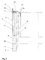
- the steel element 9 has in this case distributed on its outer circumference a plurality of holes 10 through which bolts 11 (see Fig. 3 ) are guided to fix the tower section 3 made of steel thereto.
- the adapter piece 7 according to the invention is produced by the steel element 9 upside down, ie with the later top side 14 down in an annular formwork (not shown here) is inserted. Subsequently, concrete is applied directly to the later underside of the flange 9a.
- the concrete element 8 can be produced with a particularly high quality in the head region of the concrete element 8, which is located at the top later.
- the concrete element 8 thus has in its head a very dense concrete structure with a small proportion of air inclusions.
- the flange 9a can be completely submerged, so that the highly loaded contact surface is made of high quality and substantially without air pockets.
- the steel element 9 directly form part of the formwork (not shown), in the present case the flange 9a forms an underside of the formwork.
- the adapter piece 7 can remain stored overhead after demoulding until final solidification of the concrete element 8, so that the highly stressed head portion of the adapter piece can be produced in good quality. After demoulding and hardening of the adapter piece 7 is the lower surface 15 of the adapter piece 7 and optionally the upper side 14 of the flange 9a machined material removal, to ensure the parallelism. As a result, no adjustments are required during the subsequent assembly.
- the adapter piece 7 can be prepared by the inventive design with a concrete element 8 and a steel element 9 in a favorable manner as a finished part, so that it can be made completely independent of the production of tower sections 2 and 3 made of concrete and steel.
- the adapter piece 7 according to the invention it is thus possible to produce a tower 1 completely in prefabricated construction or even completely or partially at the installation site. It is particularly advantageous in this case that the production of the tower sections 2 and 3 and the adapter piece 7 can be done completely independently of each other in time. The flexibility of the adapter piece 7 and the mounting options are thereby increased.
- the adapter piece 7 is thus also suitable for off-shore installations.
- a maximum height of the adapter piece of 3.80 m and an outer diameter of 3 - 8 m is advantageous. If a road transport is not required, then the adapter piece 7 can be made in any dimensions.
- Fig. 3 shows a further embodiment of an adapter piece 7 according to the invention in a sectional view.
- the adapter piece 7 comprises an inner annular concrete element 8 and an outer annular steel element 9, which has an inwardly facing annular flange 9a at its upper end in the installed position.
- the steel element 9 has a substantially U-shaped cross section, so that it surrounds the upper area of the concrete element 8. This can be a very good. Connection between the concrete element 8 and the steel element 9 and a particularly good load capacity of the concrete element 8 are made.
- a plurality of presently oriented vertically anchor bolts 11 are cast.
- the anchor bolts 11 are guided through corresponding bores 10 of the flange 9a and project beyond the upper side 14 of the adapter piece.
- the anchor bolts 11 may be provided with a release agent, so that they are not directly connected to the concrete element 8 and can be dismantled again. As a result, a subsequent disassembly of the tower 1 or an exchange of the anchor bolt 11 during maintenance is possible.
- the anchor bolts 11 may be encapsulated in a cladding tube to allow disassembly and replacement.
- the flange 9a of the adapter piece 7 a plurality of openings 12 for fixing tendons 13. Furthermore, in the concrete element 8 of the adapter piece 7 sheaths 19 are cast, so that a subsequent bracing of the precast concrete 6 is possible in a favorable manner.
- the tendons 13 are for this purpose passed through the Hüllrohe 19 in the concrete element 8 and the openings 12 in the flange 9a and fixed to the top 14 of the flange 9a. In the present case, the tendons 13 are fixed without anchor plate directly on the flange 9a. Only with an oblique course of the tendons 13, as shown here, a wedge plate 20 is placed under. Due to the inventive design of the flange 9a, which is connected in a particularly good manner with the concrete element 8, this can also take over the function of a load distribution plate.
- the adapter element 7 has at its lower end in the installation position a recess 21, so that the tendons are guided only in the region of the adapter piece 7 within the wall of the tower 1 and otherwise extend inside the tower outside the wall to the foot portion 4 of the tower 1, where they are also anchored.
- it may also be provided to fasten them at certain intervals along the height of the tower by means of suitable fasteners or guide elements or at least lead.
- the bias on the tower section made of concrete 2 can of course also be applied by means lying in the concrete section tendons 13.
- the precast concrete parts 5 of the tower section 2 made of concrete are placed dry in the assembly of the tower section 2 and braced against each other.
- the precast concrete elements 5 (see Fig. 4 ), which in the present case each consist of two ring segments 6, each have an upper and a lower horizontal contact surface 21. At least one of the contact surfaces 21 of the precast concrete elements 5 is machined, ie ground. This makes it possible to produce a flat contact surface 21, which allows the simple structure of the tower section 2 without elaborate adjustments. Furthermore, a smooth and smooth contact surface 21 is achieved by the revision of the contact surfaces 21, so that the precast concrete parts 5 can be clamped dry.
- the assembly is simplified and dismantling possible at any time.
- annular prefabricated concrete elements 5 consist of two or more ring segments 6, as shown here, vertical contact joints 23 are present in each ring 5 of the tower 1. These are preferably also carried out dry.
- diagonally arranged screw connections (not shown) can be provided in the region of the vertical contact joints 23.
- a fixation of the ring segments 6 to each other can also be achieved only by the biasing force of the tendons 13 and an offset of the individual ring segments 6 in each ring 5.
- the vertical Contact joints 23 of the following ring 5 each offset by 90 ° (see Fig. 1 ).
- the precast concrete parts 5, 6 at their contact surfaces 21 one or more recesses 24, in this case bores have.
- a dowel for example made of plastic, (not shown) are used, which engages in the overlying prefabricated concrete part 5, 6, so that a horizontal displacement of the precast concrete parts 5, 6 or rotation is prevented.
- a plastic anchor another element can be used to position or prevent rotation of various materials. A particularly good fixation of the individual precast concrete parts 5, 6 to each other can be achieved if, as shown here, several dowels or several recesses 24 are arranged distributed over the circumference of the precast concrete part 5, 6.
- Fig. 5 shows an alternative embodiment of an adapter piece 7 for connecting a concrete tower section 2 with a steel tower section 3 in a schematic sectional view.
- Anchor bolt 11 which is cast into the concrete element 8 of the adapter piece 7, does not extend beyond the upper side 14 of the adapter piece but ends just below the upper side 14.
- a threaded sleeve 25 is cast on the upper side 14 of the adapter piece 7 or the concrete element 8 is bolted to the cast anchor bolt 11.
- the threaded sleeve 25 is also shown cut here.
- the flange 9a of the steel element 9 also has a corresponding number of holes 10, through which further fastening means 26 for fastening the tower section 3 made of steel can be passed.
- the fastening of the tower section 3 made of steel by means of a plurality of threaded bolts which are guided through the mounting flange 16 of the tower section of steel 3 and the flange 9a and then screwed into the cast-in sleeve 25.
- the adapter piece 7 can thereby be produced in a particularly favorable manner and be transported because there are no protruding parts.
- they can also be provided with a release agent or be poured into a cladding tube.
- the anchor bolts 11 can thereby be used at the same time in an advantageous manner to apply a bias to the adapter piece 7.
- a lower anchor plate and possibly a fastening nut are in this case firmly embedded in the concrete element 8.
- the mounting flange 16 of the tower section made of steel 3 is slightly smaller in diameter than the adapter piece 7, so that it is arranged offset inwards on the adapter piece 7. In this way, a favorable load on the concrete element 8 and an improved absorption of compressive stresses can be achieved.
Priority Applications (1)
| Application Number | Priority Date | Filing Date | Title |
|---|---|---|---|
| PL11719508T PL2580408T3 (pl) | 2010-06-14 | 2011-05-04 | Wieża z elementem adapterowym oraz sposób produkcji wieży z elementem adapterowym |
Applications Claiming Priority (3)
| Application Number | Priority Date | Filing Date | Title |
|---|---|---|---|
| DE102010030047 | 2010-06-14 | ||
| DE102010039796A DE102010039796A1 (de) | 2010-06-14 | 2010-08-26 | Turm mit einem Adapterstück sowie Verfahren zur Herstellung eines Turms mit einem Adapterstück |
| PCT/EP2011/057088 WO2011157476A2 (de) | 2010-06-14 | 2011-05-04 | Turm mit einem adapterstück sowie verfahren zur herstellung eines turms mit einem adapterstück |
Publications (2)
| Publication Number | Publication Date |
|---|---|
| EP2580408A2 EP2580408A2 (de) | 2013-04-17 |
| EP2580408B1 true EP2580408B1 (de) | 2017-07-19 |
Family
ID=44626354
Family Applications (1)
| Application Number | Title | Priority Date | Filing Date |
|---|---|---|---|
| EP11719508.1A Active EP2580408B1 (de) | 2010-06-14 | 2011-05-04 | Turm mit einem adapterstück sowie verfahren zur herstellung eines turms mit einem adapterstück |
Country Status (14)
| Country | Link |
|---|---|
| US (2) | US9243418B2 (pt) |
| EP (1) | EP2580408B1 (pt) |
| JP (2) | JP2013528730A (pt) |
| CN (2) | CN102947524B (pt) |
| AU (2) | AU2011267375B2 (pt) |
| BR (2) | BR112012031422A2 (pt) |
| CA (2) | CA2802432C (pt) |
| DE (1) | DE102010039796A1 (pt) |
| DK (2) | DK2580408T3 (pt) |
| ES (2) | ES2643088T3 (pt) |
| LT (1) | LT2580408T (pt) |
| PL (1) | PL2580408T3 (pt) |
| RU (2) | RU2564328C2 (pt) |
| WO (2) | WO2011157476A2 (pt) |
Families Citing this family (69)
| Publication number | Priority date | Publication date | Assignee | Title |
|---|---|---|---|---|
| US8322093B2 (en) * | 2008-06-13 | 2012-12-04 | Tindall Corporation | Base support for wind-driven power generators |
| ES2378199B1 (es) * | 2009-06-24 | 2013-06-05 | Acciona Windpower S.A. | Sistema de unión de una góndola con la torre de hormigón de un aerogenerador. |
| SE535860C2 (sv) * | 2010-02-09 | 2013-01-15 | Erigovis Ab | Förfarande för att framställa ett torn till ett vindkraftverk |
| DE102010039796A1 (de) * | 2010-06-14 | 2011-12-15 | Max Bögl Bauunternehmung GmbH & Co. KG | Turm mit einem Adapterstück sowie Verfahren zur Herstellung eines Turms mit einem Adapterstück |
| BR112013000910B1 (pt) | 2010-07-13 | 2020-02-27 | Andresen Towers A/S | Método de montagem de uma estrutura de construção tubular e torre de turbina eólica |
| US9394035B2 (en) * | 2010-11-04 | 2016-07-19 | University Of Maine System Board Of Trustees | Floating wind turbine platform and method of assembling |
| DE102011090194B4 (de) * | 2011-12-30 | 2013-12-05 | Rolf J. Werner | Turmförmiges Tragwerk |
| DE102012001109A1 (de) | 2012-01-23 | 2013-07-25 | Drössler GmbH Umwelttechnik | Hybridturm |
| CA2880788C (en) | 2012-08-03 | 2020-03-24 | James D. Lockwood | Precast concrete post tensioned segmented wind turbine tower |
| DE102012015489A1 (de) | 2012-08-04 | 2014-02-06 | E.N.O. Energy Systems Gmbh | Verfahren zum Errichten eines Turmes aus Stahl einer Windenergieanlage und Turm aus Stahl für eine Windenergieanlage |
| ES2438626B1 (es) * | 2012-10-01 | 2014-09-10 | Gestamp Hybrid Towers, S.L. | Estructura de soporte para aerogeneradores y molde para obtener tales estructuras |
| DE102012109860A1 (de) * | 2012-10-16 | 2014-04-17 | Max Bögl Wind AG | Versorgungsgerüst für einen Turm,Turm mit einem Versorgungsgerüst sowie Verfahren zum Errichten eines Versorgungsgerüsts im Inneren eines Turms |
| GB2507803B (en) * | 2012-11-12 | 2015-07-29 | Ship & Ocean Ind R & D Ct | An offshore installation method of a wind power generator and its fabrication segments |
| ES2471641B1 (es) * | 2012-12-21 | 2015-04-07 | Acciona Windpower, S.A. | Dovela prefabricada de hormigón, torre de aerogenerador que comprende dicha dovela, aerogenerador que comprende dicha torre y procedimiento de montaje de dicho aerogenerador |
| ES2472306B1 (es) | 2012-12-27 | 2015-06-02 | Acciona Windpower, S.A. | Molde para la fabricación de prefabricados de hormigón |
| DE102013100176B4 (de) * | 2013-01-09 | 2014-10-02 | Europoles Gmbh & Co. Kg | Turm, insbesondere für Stromleitungen |
| US9745770B2 (en) * | 2013-02-05 | 2017-08-29 | Tindall Corporation | Cruciform tower |
| US20150052841A1 (en) * | 2013-02-05 | 2015-02-26 | Tindall Corporation | Structure including non-structural joint |
| DE102013105512A1 (de) * | 2013-05-29 | 2014-12-04 | Max Bögl Wind AG | Betonfundament und Verfahren zur Herstellung eines Betonfundaments für einen Windkraftturm sowie Positioniervorrichtung zur Positionierung von Hüllrohren in einem Betonfundament |
| DE102013107059B4 (de) | 2013-07-04 | 2018-12-06 | SIAG Industrie GmbH | Verfahren zur Herstellung und zum Errichten eines Rohrturmbauwerks |
| DE102013213976A1 (de) * | 2013-07-17 | 2015-01-22 | Wobben Properties Gmbh | Verfahren zum Herstellen eines Fertigbetonteil-Segmentes eines Windenergieanlagen-Turmes |
| MX2016002256A (es) * | 2013-08-22 | 2016-09-07 | Tindall Corp | Torre cruciforme. |
| EP2846040B1 (en) * | 2013-09-06 | 2018-03-21 | youWINenergy GmbH | Tower assembly for a wind turbine installation |
| CN114962165A (zh) * | 2014-02-06 | 2022-08-30 | 缅因大学系统委员会 | 组装漂浮式风力涡轮机平台的方法 |
| CN103883482B (zh) * | 2014-03-28 | 2017-03-29 | 北京金风科创风电设备有限公司 | 预制混凝土筒节及其制造方法及风力发电机组塔筒 |
| DE102015115645A1 (de) | 2015-09-16 | 2017-03-16 | SIAG Industrie GmbH | Verfahren zur Herstellung und zum Errichten eines Rohrturmbauwerks |
| DE102014118251B4 (de) | 2014-12-09 | 2017-05-04 | SIAG Industrie GmbH | Verfahren zur Herstellung und zum Errichten eines Rohrturmbauwerks |
| WO2016091499A1 (de) | 2014-12-09 | 2016-06-16 | SIAG Industrie GmbH | Verfahren zur herstellung und zum errichten eines rohrturmbauwerks |
| MX2017008938A (es) | 2015-01-09 | 2018-05-17 | Tindall Corp | Torre y metodo para construir una torre. |
| EP3247848A4 (en) * | 2015-01-09 | 2018-12-19 | Tindall Corporation | Tower and method for constructing a tower |
| ES2589962B1 (es) * | 2015-04-17 | 2017-09-08 | Gamesa Innovation & Technology, S.L. | Dispositivo de unión de un tramo metálico con un tramo de hormigón en una torre hueca híbrida |
| CN104889838B (zh) * | 2015-04-22 | 2018-07-31 | 北京金风科创风电设备有限公司 | 预制混凝土塔段的切削机床及切削方法 |
| DE102015111109A1 (de) * | 2015-07-09 | 2017-01-12 | Vensys Energy Ag | Turm einer Windkraftanlage |
| WO2017040019A1 (en) * | 2015-08-31 | 2017-03-09 | Siemens Energy, Inc. | Tower segment and method utilizing segmented bearing plate |
| DE102016115042A1 (de) * | 2015-09-15 | 2017-03-30 | Max Bögl Wind AG | Turm für eine Windkraftanlage aus ringsegmentförmigen Betonfertigteilen |
| DE102015115562A1 (de) * | 2015-09-15 | 2017-03-16 | Max Bögl Wind AG | Turm für eine Windkraftanlage mit einem Wasserspeicher eines Pumpspeicherkraftwerks, Wasserspeicherbecken eines Pumpspeicherkraftwerks und Anlage zur Energieerzeugung |
| DE102015115646A1 (de) | 2015-09-16 | 2017-03-16 | SIAG Industrie GmbH | Türkonstruktion für ein Rohrturmbauwerk |
| DE102015014458A1 (de) | 2015-09-16 | 2017-03-16 | Senvion Gmbh | Türkonstruktion für ein Rohrturmbauwerk |
| DE102016203494A1 (de) * | 2016-01-20 | 2017-07-20 | Ventur GmbH | Adaptervorrichtung für einen Turm und Verfahren zur Herstellung |
| JP2017145714A (ja) * | 2016-02-16 | 2017-08-24 | クリーンエナジーファクトリー株式会社 | 風力発電機 |
| CN106481515A (zh) * | 2016-10-08 | 2017-03-08 | 霍尔果斯新国金新能源科技有限公司 | 混凝土塔筒组件及其张拉方法 |
| DE102016125062A1 (de) * | 2016-12-21 | 2018-06-21 | Wobben Properties Gmbh | Windenergieanlagen-Turm und Windenergieanlagen-Turmübergangssegment |
| EP3339636A1 (de) | 2016-12-22 | 2018-06-27 | Nordex Energy GmbH | Stahlturm für eine windenergieanlage sowie ein verfahren zu dessen herstellung |
| EP3339635A1 (de) | 2016-12-22 | 2018-06-27 | Nordex Energy GmbH | Stahlturm für eine windenergieanlage sowie verfahren zur herstellung desselben |
| CN106704108A (zh) * | 2017-03-01 | 2017-05-24 | 北京建筑大学 | 一种混凝土塔筒与钢塔筒的连接方式 |
| DE102017125060A1 (de) * | 2017-10-26 | 2019-05-02 | Wobben Properties Gmbh | Ringförmige Konsole zum externen Spannen eines Turmsegments, externes Spannsystem eines Hybridturms, Turmabschnitt eines Hybridturms, Hybridturm, Windenergieanlage und Montageverfahren eines externen Spannsystems für einen Hybridturm |
| DE102017009984A1 (de) * | 2017-10-26 | 2019-05-02 | Senvion Gmbh | Turm mit konischen Stahladapterelementen |
| DE102017011046A1 (de) | 2017-11-29 | 2019-05-29 | Senvion Gmbh | Turmsegment für eine Windenergieanlage und Verfahren zum Herstellen eines Turmsegments |
| CN108223294A (zh) * | 2018-01-31 | 2018-06-29 | 浙江运达风电股份有限公司 | 一种混凝土塔筒高空用预应力穿筋及锚栓调平装置 |
| DE102018105276A1 (de) * | 2018-03-07 | 2019-09-12 | Max Bögl Wind AG | Verfahren zum Einbringen von Spanngliedern in einen Turm, Montagevorrichtung, Abtrommelvorrichtung und Adaptervorrichtung |
| DE102018106998A1 (de) | 2018-03-23 | 2019-09-26 | Wobben Properties Gmbh | Halbfertigteil für ein Fundament eines Turmbauwerks, Halbfertigteil-Fundamentsegment, Fundament, Verfahren zum Herstellen eines Halbfertigteils sowie Verfahren zum Herstellen eines Fundaments |
| ES2726226B2 (es) * | 2018-04-02 | 2021-05-28 | Structural Concrete & Steel S L | Poste prefabricado de hormigon |
| CN109139386B (zh) * | 2018-09-30 | 2019-08-23 | 北京金风科创风电设备有限公司 | 塔筒段、塔筒、分割方法及风力发电机组 |
| EP3670899B1 (en) * | 2018-12-21 | 2024-03-13 | Nordex Energy Spain, S.A.U. | Method for assembling a wind turbine and wind turbine assembled according to said method |
| DE102019103589A1 (de) | 2019-02-13 | 2020-08-13 | Wobben Properties Gmbh | Hybrid-Turmabschnitt, Hybrid-Turm für eine Windenergieanlage sowie Herstellungsverfahren |
| US11274465B2 (en) | 2020-01-03 | 2022-03-15 | Nov Canada Ulc | Tower erection and climbing systems |
| CN111571407A (zh) * | 2020-05-22 | 2020-08-25 | 黄伟芬 | 一种预制混凝土塔段的自动切削设备 |
| CN113090468A (zh) * | 2021-03-09 | 2021-07-09 | 中国电建集团西北勘测设计研究院有限公司 | 一种分片式预制混凝土风机塔筒及建造方法 |
| US11754048B2 (en) | 2021-03-25 | 2023-09-12 | National Oilwell Varco, L.P. | Tower erection system |
| WO2022263697A1 (es) * | 2021-06-14 | 2022-12-22 | Hws Concrete Towers, S.L. | Torre de gran altura con elementos prefabricados de hormigón |
| WO2023287401A1 (en) | 2021-07-13 | 2023-01-19 | General Electric Company | Wind turbine tower structure with transition system between sections thereof |
| BR112023027432A2 (pt) | 2021-07-22 | 2024-03-12 | Windtechnic Eng S L | Torre de concreto possuindo múltiplas seções |
| EP4230825A1 (en) | 2022-02-17 | 2023-08-23 | Siemens Gamesa Renewable Energy Innovation & Technology S.L. | Tower connector |
| CN114753402A (zh) * | 2022-04-06 | 2022-07-15 | 中国船舶重工集团海装风电股份有限公司 | 一种用于风电塔架的钢混组合结构转接段 |
| EP4345297A1 (en) * | 2022-09-27 | 2024-04-03 | Nordex Energy Spain, S.A.U. | Tower of a wind turbine |
| WO2024068731A1 (en) * | 2022-09-27 | 2024-04-04 | Nordex Energy Spain, S.A.U. | Concrete segment of a section of a tower of a wind turbine and adapter of a tower of a wind turbine tower |
| WO2024068727A1 (en) * | 2022-09-27 | 2024-04-04 | Nordex Energy Se & Co. Kg | Tower of a wind turbine |
| WO2024068720A1 (en) * | 2022-09-27 | 2024-04-04 | Nordex Energy Se & Co. Kg | Concrete segment of a section of a tower of a wind turbine and adapter of a tower of a wind turbine tower |
| EP4343145A1 (en) * | 2023-06-21 | 2024-03-27 | Nordex Energy Spain, S.A.U. | Set of concrete segments of adjacent sections of a wind turbine tower, and method of assembling a wind turbine |
Citations (1)
| Publication number | Priority date | Publication date | Assignee | Title |
|---|---|---|---|---|
| EP2009202A2 (de) * | 2007-06-28 | 2008-12-31 | Nordex Energy GmbH | Windenergieanlagenturm |
Family Cites Families (67)
| Publication number | Priority date | Publication date | Assignee | Title |
|---|---|---|---|---|
| DE2326192A1 (de) | 1973-05-23 | 1974-12-12 | Alex Walser | Verfahren zur herstellung von mauersteinen und schalungssteinen mit praezisen hoehenmassen |
| US4042659A (en) | 1974-05-06 | 1977-08-16 | Alden Joseph Botting | Method of molding modular buildings |
| US4206163A (en) * | 1977-03-28 | 1980-06-03 | Decoster James W | Jobsite apparatus for horizontal casting and vertical stacking of thick insulated concrete panels |
| US4374790A (en) | 1980-07-08 | 1983-02-22 | Marley Company | Method and apparatus for pumping concrete to form structure at elevated heights |
| US4878160A (en) * | 1988-03-11 | 1989-10-31 | Reneau George W | Outdoor lightpole |
| US4890420A (en) | 1988-03-21 | 1990-01-02 | Hossein Azimi | Grinding machine |
| EP0507945B1 (de) | 1989-10-30 | 1998-03-18 | DOLGOPOLOV, Vladimir Nikolaevich | Verfahren und brennvorrichtung zur herstellung von keramischen erzeugnissen für den bau |
| US6340790B1 (en) * | 1990-01-31 | 2002-01-22 | Musco Corporation | Means and method for integrated lighting fixture supports and components |
| US5186881A (en) * | 1990-04-02 | 1993-02-16 | Beaman Samuel W | Method for manufacturing hollow concrete structures |
| JPH0448745A (ja) | 1990-06-14 | 1992-02-18 | Mitsubishi Electric Corp | 薄膜の耐摩耗性評価方法 |
| DE4293518T1 (de) * | 1991-10-22 | 1996-04-25 | Weiland Pamela | Verbesserungen an oder bezogen auf Bodenfräsmaschinen |
| SE501993C2 (sv) * | 1992-01-29 | 1995-07-10 | Sjoedin Sven Eric | Roterande verktyg innefattande ett roterbart lagrat nav omkring vars omkrets ett antal bearbetningsspetsar är anordnade |
| US5956911A (en) | 1993-02-10 | 1999-09-28 | Kistner Concrete Products, Inc. | Insulated pre-formed wall panels |
| RU2046710C1 (ru) | 1993-06-03 | 1995-10-27 | Государственный научно-технический, проектно-конструкторский и технологический Центр комплексного развития и использования сырьевой базы строительной индустрии "Гран" | Станок для калибровки бруса из природного камня |
| US5335160A (en) * | 1993-07-13 | 1994-08-02 | Duraline | Mast-type outdoor lighting system |
| US5586417A (en) * | 1994-11-23 | 1996-12-24 | Henderson; Allan P. | Tensionless pier foundation |
| CN1125801A (zh) | 1994-11-30 | 1996-07-03 | E.R.C.株式会社 | 控制大体积混凝土结构物温度应力的混凝土浇筑方法 |
| US5643488A (en) | 1994-12-16 | 1997-07-01 | Daewoo Hawaii Corporation | Multi-room modular construction system |
| JPH09248745A (ja) * | 1996-03-13 | 1997-09-22 | Nippon Ryosuiki Kogyo Kk | レジンコンクリート製下枡の端面研削装置 |
| US5878540A (en) * | 1997-09-12 | 1999-03-09 | Site Photometrics, Inc. | Utility pole base pan with drain |
| DE19823650C2 (de) * | 1998-05-27 | 2001-05-23 | Wilfried Arand | Verfahren und Vorrichtung zum Herstellen von hohen, hohlen, turmartigen Bauwerken von bis zu zweihundert Metern Höhe und mehr, insbesondere von Türmen für Windkraftanlagen |
| DE19916378C2 (de) * | 1999-04-12 | 2003-08-21 | Wacker Construction Equipment | Innenrüttelvorrichtung mit veränderbarer Schwingungsamplitude |
| DE19928785A1 (de) * | 1999-06-23 | 2001-01-11 | Leonhard Moll Betonwerke Gmbh | Herstellung von Betonschwellen für Eisenbahnschienen |
| DE10033845A1 (de) | 2000-07-12 | 2002-01-24 | Aloys Wobben | Turm aus Spannbeton-Fertigteilen |
| DE10133607C5 (de) | 2001-02-14 | 2010-08-19 | Max Bögl Bauunternehmung GmbH & Co. KG | Verfahren und Palette zur Herstellung eines präzisen Betonfertigteiles |
| AU2002240897A1 (en) * | 2001-02-14 | 2002-08-28 | Max Bogl Bauunternehmung Gmbh And Co. Kg | Method and pallet for the production of a precise pre-cast concrete piece |
| DE10108139A1 (de) * | 2001-02-20 | 2002-08-29 | Boegl Max Bauunternehmung Gmbh | Verfahren zur Vermessung und/oder Bearbeitung eines Werkstücks |
| US6851231B2 (en) * | 2001-06-27 | 2005-02-08 | Maher K. Tadros | Precast post-tensioned segmental pole system |
| NL1019953C2 (nl) * | 2002-02-12 | 2002-12-19 | Mecal Applied Mechanics B V | Geprefabriceerde toren of mast, alsmede een methode voor het samenvoegen en/of naspannen van segmenten die één constructie moeten vormen, alsmede een werkwijze voor het opbouwen van een toren of mast bestaande uit segmenten. |
| DE10230273B3 (de) | 2002-07-05 | 2004-02-12 | Institut für Fertigteiltechnik und Fertigbau Weimar e.V. | Turm einer Windkraftanlage mit einem unteren Teil aus Spannbeton und einem aufgesetzten Stahlrohr |
| WO2004007955A1 (de) | 2002-07-16 | 2004-01-22 | Aloys Wobben | Verfahren zur herstellung eines turmsegments einer windenergieanlage |
| US20050121830A1 (en) | 2003-07-29 | 2005-06-09 | Ness John T. | Masonry blocks and method and system of making masonry blocks |
| US20050120670A1 (en) | 2003-07-29 | 2005-06-09 | Ness John T. | Masonry blocks and method and system of making masonry blocks |
| CA2533806C (en) * | 2003-08-09 | 2012-06-19 | General Electric Company | Tower foundation, in particular for a wind energy turbine |
| DE10349155A1 (de) * | 2003-10-22 | 2005-05-19 | Dennert Poraver Gmbh | Verfahren zur Erstellung einer planen Gebäudedecke und dabei verwendete Deckenplatten |
| US20050110197A1 (en) | 2003-11-20 | 2005-05-26 | Guy Deffense | Concrete pole cast molding system and method |
| US7500845B2 (en) | 2005-01-13 | 2009-03-10 | Ness Inventions, Inc. | Apparatus and method for forming retaining wall blocks with variable depth flanges |
| CN100371555C (zh) * | 2005-11-16 | 2008-02-27 | 黄修文 | 电动多功能建筑罩面装修机 |
| DE102006001026A1 (de) * | 2006-01-03 | 2007-07-05 | Gleason-Pfauter Maschinenfabrik Gmbh | Werkzeugkopf zur Aufnahme und zum Antrieb der Drehbewegung eines zweiseitig zu lagernden Werkzeuges sowie Werkzeug zum Einsatz in einem solchen Werkzeugkopf |
| DE102006015838A1 (de) | 2006-04-03 | 2007-10-04 | Rolls-Royce Deutschland Ltd & Co Kg | Axialkompressor für ein Gasturbinentriebwerk |
| CN2895630Y (zh) * | 2006-04-05 | 2007-05-02 | 叶天云 | 钢管连接结构 |
| DE202006009554U1 (de) | 2006-06-16 | 2006-11-02 | Oevermann Gmbh & Co. Kg | Hybrides Turmbauwerk |
| RU2344253C2 (ru) * | 2007-02-19 | 2009-01-20 | Федеральное государственное унитарное предприятие "Авангард" (ФГУП "Авангард") | Газоотводящий ствол дымовой трубы |
| WO2009056898A1 (es) | 2007-11-02 | 2009-05-07 | Alejandro Cortina-Cordero | Torre de concreto postensado para generadores eolicos |
| GB0716733D0 (en) * | 2007-08-30 | 2007-10-10 | Reactec Ltd | Tower |
| CL2009000371A1 (es) | 2008-03-03 | 2009-10-30 | United States Gypsum Co | Composicion cementicia, que contiene una fase continua que resulta del curado de una mezcla cementicia, en ausencia de harina de silice, y que comprende cemento inorganico, mineral inorganico, relleno puzolanico, policarboxilato y agua; y uso de la composicion en una panel y barrera cementicia. |
| DE102008015838A1 (de) * | 2008-03-27 | 2009-10-01 | Danijel Golub | Streifen-Ringe-Ronden-Schneidsysteme |
| DE102008016828A1 (de) | 2008-04-01 | 2009-10-15 | Wobben, Aloys | Verfahren zur Herstellung von Betonfertigteilen |
| DE102008041849A1 (de) | 2008-09-05 | 2010-03-25 | Max Bögl Bauunternehmung GmbH & Co. KG | Off-Shore-Anlage, Fundament einer Off-Shore-Anlage und Verfahren zum Errichten einer Off-Shore-Anlage |
| EP2342056A4 (en) | 2008-10-08 | 2012-08-29 | Ericsson Telefon Ab L M | METHOD FOR MANUFACTURING HOLLOW CONCRETE ELEMENTS |
| JPWO2010044380A1 (ja) * | 2008-10-15 | 2012-03-15 | 株式会社竹中工務店 | 塔状構造物、及び塔状構造物の構築方法 |
| US8555600B2 (en) | 2008-12-10 | 2013-10-15 | Cortina Innovations, S.A. De C.V. | Method for mounting in sections an annular tower for wind power generator, heliostatic power generator or chimney composed from three concrete segments or more |
| DE102009013186B4 (de) * | 2008-12-19 | 2015-05-28 | Senvion Se | Turm einer Windenergieanlage |
| CN201326524Y (zh) * | 2008-12-24 | 2009-10-14 | 华锐风电科技有限公司 | 风力发电机组混合式塔筒 |
| JP5260268B2 (ja) | 2008-12-26 | 2013-08-14 | 日立Geニュークリア・エナジー株式会社 | 原子力発電プラント用炉心シュラウドの製造方法及び原子力発電プラント構造物 |
| DE102009016893B4 (de) * | 2009-04-08 | 2011-12-08 | Nordex Energy Gmbh | Verankerungsbauteil für einen Windenergieanlagenturm |
| US20100281818A1 (en) * | 2009-05-07 | 2010-11-11 | Southworth George L | Method for building wind turbine tower |
| ES2378199B1 (es) * | 2009-06-24 | 2013-06-05 | Acciona Windpower S.A. | Sistema de unión de una góndola con la torre de hormigón de un aerogenerador. |
| DE102009049435A1 (de) * | 2009-10-14 | 2011-04-28 | Wobben, Aloys | Verfahren zum Herstellen von Betonfertigteilen und Schalungseinheit zum Herste llen von Betonfertigteilen |
| DE202010000169U1 (de) | 2010-02-11 | 2010-05-12 | B+S Gmbh | Gussteil mit planparallelen Flächen und Vorrichtung zu dessen Herstellung |
| EP2375057B1 (en) * | 2010-03-31 | 2016-05-04 | Siemens Aktiengesellschaft | Wind turbine installation |
| US20110131899A1 (en) * | 2010-04-30 | 2011-06-09 | Stefan Voss | Apparatus and method for producing a concrete foundation |
| DE102010039796A1 (de) * | 2010-06-14 | 2011-12-15 | Max Bögl Bauunternehmung GmbH & Co. KG | Turm mit einem Adapterstück sowie Verfahren zur Herstellung eines Turms mit einem Adapterstück |
| DE102011078016A1 (de) * | 2011-06-22 | 2012-12-27 | Aloys Wobben | Turmfertigung |
| ES2703529T3 (es) * | 2011-11-24 | 2019-03-11 | Wobben Properties Gmbh | Dispositivo y procedimiento para rectificar un segmento de torre de hormigón de una turbina eólica |
| DE102012104508A1 (de) | 2012-05-24 | 2013-11-28 | Max Bögl Wind AG | Turmbauwerk einer Windkraftanlage sowie Verfahren zum Errichten eines Turmbauwerks |
| US8808604B2 (en) * | 2012-08-21 | 2014-08-19 | Pu Song Won | Concrete pole and manufacturing method therefor |
-
2010
- 2010-08-26 DE DE102010039796A patent/DE102010039796A1/de not_active Withdrawn
-
2011
- 2011-05-04 CA CA2802432A patent/CA2802432C/en active Active
- 2011-05-04 US US13/704,263 patent/US9243418B2/en active Active
- 2011-05-04 WO PCT/EP2011/057088 patent/WO2011157476A2/de active Application Filing
- 2011-05-04 AU AU2011267375A patent/AU2011267375B2/en not_active Ceased
- 2011-05-04 CN CN201180030352.6A patent/CN102947524B/zh not_active Expired - Fee Related
- 2011-05-04 LT LTEP11719508.1T patent/LT2580408T/lt unknown
- 2011-05-04 RU RU2013100498/03A patent/RU2564328C2/ru active
- 2011-05-04 BR BR112012031422A patent/BR112012031422A2/pt active Search and Examination
- 2011-05-04 EP EP11719508.1A patent/EP2580408B1/de active Active
- 2011-05-04 PL PL11719508T patent/PL2580408T3/pl unknown
- 2011-05-04 ES ES11719508.1T patent/ES2643088T3/es active Active
- 2011-05-04 DK DK11719508.1T patent/DK2580408T3/en active
- 2011-05-04 JP JP2013514608A patent/JP2013528730A/ja not_active Withdrawn
- 2011-06-10 WO PCT/EP2011/059713 patent/WO2011157659A1/de active Application Filing
- 2011-06-10 JP JP2013514662A patent/JP2013531761A/ja not_active Withdrawn
- 2011-06-10 CA CA2802442A patent/CA2802442C/en active Active
- 2011-06-10 US US13/704,265 patent/US9091095B2/en active Active
- 2011-06-10 BR BR112012031424-6A patent/BR112012031424B1/pt not_active IP Right Cessation
- 2011-06-10 RU RU2013100333/03A patent/RU2564422C2/ru active
- 2011-06-10 DK DK11728210.3T patent/DK2580409T3/en active
- 2011-06-10 AU AU2011267203A patent/AU2011267203B2/en active Active
- 2011-06-10 CN CN201180030351.1A patent/CN102939427B/zh active Active
- 2011-06-10 ES ES11728210.3T patent/ES2614861T3/es active Active
Patent Citations (1)
| Publication number | Priority date | Publication date | Assignee | Title |
|---|---|---|---|---|
| EP2009202A2 (de) * | 2007-06-28 | 2008-12-31 | Nordex Energy GmbH | Windenergieanlagenturm |
Also Published As
Similar Documents
| Publication | Publication Date | Title |
|---|---|---|
| EP2580408B1 (de) | Turm mit einem adapterstück sowie verfahren zur herstellung eines turms mit einem adapterstück | |
| EP2776637B1 (de) | Fundament einer windenergieanlage | |
| EP3516121B1 (de) | Fundament für eine windmühle | |
| EP2529111B1 (de) | Windenergieanlage und windenergieanlagen-turmsegment | |
| EP1262614B1 (de) | Turmbauwerk aus Spannbeton | |
| EP2009202B1 (de) | Windenergieanlagenturm | |
| EP2239376B1 (de) | Verankerungsbauteil für einen Windenergieanlagenturm | |
| EP1767705B1 (de) | Verfahren zur Gründung eines Fundamentkörpers für eine Windenergieanlage | |
| EP2744955B1 (de) | Vorrichtung und verfahren für den übergang zwischen einem aufgehenden turmabschnitt und einem vorgespannten betonturmabschnitt | |
| EP3821083B1 (de) | Fundament für ein windkraftwerk | |
| EP2729621B1 (de) | Anordnung zum abstützen eines zugglieds, insbesondere eines schrägseils, quer zu seiner längserstreckungsrichtung | |
| AT519189B1 (de) | Fundament für eine Windmühle | |
| EP2108836B1 (de) | Verankerung eines Turms einer Windenergieanlage | |
| EP3350391A2 (de) | Turm für eine windkraftanlage aus ringsegmentförmigen betonfertigteilen | |
| DE102018107421A1 (de) | Fundament für ein mittels einer Vielzahl von Spanngliedern vorgespanntes Bauwerk sowie mittels einer Vielzahl von Spanngliedern vorgespanntes Bauwerk | |
| WO2013110448A1 (de) | Hybridturm | |
| EP3931399A1 (de) | Fundament für eine windkraftanlage | |
| DE102015115562A1 (de) | Turm für eine Windkraftanlage mit einem Wasserspeicher eines Pumpspeicherkraftwerks, Wasserspeicherbecken eines Pumpspeicherkraftwerks und Anlage zur Energieerzeugung | |
| EP2580409B1 (de) | Turm einer windenergieanlage sowie verfahren zur herstellung eines turms einer windenergieanlage |
Legal Events
| Date | Code | Title | Description |
|---|---|---|---|
| PUAI | Public reference made under article 153(3) epc to a published international application that has entered the european phase |
Free format text: ORIGINAL CODE: 0009012 |
|
| 17P | Request for examination filed |
Effective date: 20130114 |
|
| AK | Designated contracting states |
Kind code of ref document: A2 Designated state(s): AL AT BE BG CH CY CZ DE DK EE ES FI FR GB GR HR HU IE IS IT LI LT LU LV MC MK MT NL NO PL PT RO RS SE SI SK SM TR |
|
| DAX | Request for extension of the european patent (deleted) | ||
| RAP1 | Party data changed (applicant data changed or rights of an application transferred) |
Owner name: MAX BOEGL STIFTUNG & CO. KG |
|
| 17Q | First examination report despatched |
Effective date: 20150303 |
|
| REG | Reference to a national code |
Ref country code: DE Ref legal event code: R079 Ref document number: 502011012660 Country of ref document: DE Free format text: PREVIOUS MAIN CLASS: E04H0012000000 Ipc: F03D0013200000 |
|
| GRAP | Despatch of communication of intention to grant a patent |
Free format text: ORIGINAL CODE: EPIDOSNIGR1 |
|
| RIC1 | Information provided on ipc code assigned before grant |
Ipc: E04H 12/16 20060101ALI20170113BHEP Ipc: B24B 7/22 20060101ALI20170113BHEP Ipc: E04H 12/08 20060101ALI20170113BHEP Ipc: B24B 27/00 20060101ALI20170113BHEP Ipc: F03D 1/00 20060101ALI20170113BHEP Ipc: E04H 12/12 20060101ALI20170113BHEP Ipc: B24B 7/16 20060101ALI20170113BHEP Ipc: F03D 13/20 20160101AFI20170113BHEP |
|
| INTG | Intention to grant announced |
Effective date: 20170210 |
|
| GRAS | Grant fee paid |
Free format text: ORIGINAL CODE: EPIDOSNIGR3 |
|
| GRAA | (expected) grant |
Free format text: ORIGINAL CODE: 0009210 |
|
| AK | Designated contracting states |
Kind code of ref document: B1 Designated state(s): AL AT BE BG CH CY CZ DE DK EE ES FI FR GB GR HR HU IE IS IT LI LT LU LV MC MK MT NL NO PL PT RO RS SE SI SK SM TR |
|
| REG | Reference to a national code |
Ref country code: GB Ref legal event code: FG4D Free format text: NOT ENGLISH |
|
| REG | Reference to a national code |
Ref country code: CH Ref legal event code: EP |
|
| REG | Reference to a national code |
Ref country code: IE Ref legal event code: FG4D Free format text: LANGUAGE OF EP DOCUMENT: GERMAN |
|
| REG | Reference to a national code |
Ref country code: AT Ref legal event code: REF Ref document number: 910664 Country of ref document: AT Kind code of ref document: T Effective date: 20170815 |
|
| REG | Reference to a national code |
Ref country code: DE Ref legal event code: R096 Ref document number: 502011012660 Country of ref document: DE |
|
| REG | Reference to a national code |
Ref country code: DK Ref legal event code: T3 Effective date: 20171024 |
|
| REG | Reference to a national code |
Ref country code: NL Ref legal event code: FP |
|
| REG | Reference to a national code |
Ref country code: SE Ref legal event code: TRGR |
|
| REG | Reference to a national code |
Ref country code: ES Ref legal event code: FG2A Ref document number: 2643088 Country of ref document: ES Kind code of ref document: T3 Effective date: 20171121 |
|
| REG | Reference to a national code |
Ref country code: EE Ref legal event code: FG4A Ref document number: E014508 Country of ref document: EE Effective date: 20171010 |
|
| REG | Reference to a national code |
Ref country code: NO Ref legal event code: T2 Effective date: 20170719 |
|
| PG25 | Lapsed in a contracting state [announced via postgrant information from national office to epo] |
Ref country code: HR Free format text: LAPSE BECAUSE OF FAILURE TO SUBMIT A TRANSLATION OF THE DESCRIPTION OR TO PAY THE FEE WITHIN THE PRESCRIBED TIME-LIMIT Effective date: 20170719 |
|
| PG25 | Lapsed in a contracting state [announced via postgrant information from national office to epo] |
Ref country code: RS Free format text: LAPSE BECAUSE OF FAILURE TO SUBMIT A TRANSLATION OF THE DESCRIPTION OR TO PAY THE FEE WITHIN THE PRESCRIBED TIME-LIMIT Effective date: 20170719 Ref country code: BG Free format text: LAPSE BECAUSE OF FAILURE TO SUBMIT A TRANSLATION OF THE DESCRIPTION OR TO PAY THE FEE WITHIN THE PRESCRIBED TIME-LIMIT Effective date: 20171019 Ref country code: IS Free format text: LAPSE BECAUSE OF FAILURE TO SUBMIT A TRANSLATION OF THE DESCRIPTION OR TO PAY THE FEE WITHIN THE PRESCRIBED TIME-LIMIT Effective date: 20171119 Ref country code: GR Free format text: LAPSE BECAUSE OF FAILURE TO SUBMIT A TRANSLATION OF THE DESCRIPTION OR TO PAY THE FEE WITHIN THE PRESCRIBED TIME-LIMIT Effective date: 20171020 |
|
| REG | Reference to a national code |
Ref country code: DE Ref legal event code: R097 Ref document number: 502011012660 Country of ref document: DE |
|
| PG25 | Lapsed in a contracting state [announced via postgrant information from national office to epo] |
Ref country code: RO Free format text: LAPSE BECAUSE OF FAILURE TO SUBMIT A TRANSLATION OF THE DESCRIPTION OR TO PAY THE FEE WITHIN THE PRESCRIBED TIME-LIMIT Effective date: 20170719 Ref country code: CZ Free format text: LAPSE BECAUSE OF FAILURE TO SUBMIT A TRANSLATION OF THE DESCRIPTION OR TO PAY THE FEE WITHIN THE PRESCRIBED TIME-LIMIT Effective date: 20170719 |
|
| REG | Reference to a national code |
Ref country code: FR Ref legal event code: PLFP Year of fee payment: 8 |
|
| PLBE | No opposition filed within time limit |
Free format text: ORIGINAL CODE: 0009261 |
|
| STAA | Information on the status of an ep patent application or granted ep patent |
Free format text: STATUS: NO OPPOSITION FILED WITHIN TIME LIMIT |
|
| PG25 | Lapsed in a contracting state [announced via postgrant information from national office to epo] |
Ref country code: SK Free format text: LAPSE BECAUSE OF FAILURE TO SUBMIT A TRANSLATION OF THE DESCRIPTION OR TO PAY THE FEE WITHIN THE PRESCRIBED TIME-LIMIT Effective date: 20170719 Ref country code: SM Free format text: LAPSE BECAUSE OF FAILURE TO SUBMIT A TRANSLATION OF THE DESCRIPTION OR TO PAY THE FEE WITHIN THE PRESCRIBED TIME-LIMIT Effective date: 20170719 |
|
| 26N | No opposition filed |
Effective date: 20180420 |
|
| PGFP | Annual fee paid to national office [announced via postgrant information from national office to epo] |
Ref country code: DK Payment date: 20180517 Year of fee payment: 8 Ref country code: NO Payment date: 20180522 Year of fee payment: 8 Ref country code: FI Payment date: 20180521 Year of fee payment: 8 |
|
| PG25 | Lapsed in a contracting state [announced via postgrant information from national office to epo] |
Ref country code: SI Free format text: LAPSE BECAUSE OF FAILURE TO SUBMIT A TRANSLATION OF THE DESCRIPTION OR TO PAY THE FEE WITHIN THE PRESCRIBED TIME-LIMIT Effective date: 20170719 |
|
| PGFP | Annual fee paid to national office [announced via postgrant information from national office to epo] |
Ref country code: NL Payment date: 20180517 Year of fee payment: 8 |
|
| PG25 | Lapsed in a contracting state [announced via postgrant information from national office to epo] |
Ref country code: MT Free format text: LAPSE BECAUSE OF FAILURE TO SUBMIT A TRANSLATION OF THE DESCRIPTION OR TO PAY THE FEE WITHIN THE PRESCRIBED TIME-LIMIT Effective date: 20170719 |
|
| REG | Reference to a national code |
Ref country code: LT Ref legal event code: MM4D Effective date: 20180504 |
|
| REG | Reference to a national code |
Ref country code: CH Ref legal event code: PL |
|
| REG | Reference to a national code |
Ref country code: EE Ref legal event code: MM4A Ref document number: E014508 Country of ref document: EE Effective date: 20180531 |
|
| GBPC | Gb: european patent ceased through non-payment of renewal fee |
Effective date: 20180504 |
|
| PG25 | Lapsed in a contracting state [announced via postgrant information from national office to epo] |
Ref country code: EE Free format text: LAPSE BECAUSE OF NON-PAYMENT OF DUE FEES Effective date: 20180531 Ref country code: LT Free format text: LAPSE BECAUSE OF NON-PAYMENT OF DUE FEES Effective date: 20180504 Ref country code: MC Free format text: LAPSE BECAUSE OF FAILURE TO SUBMIT A TRANSLATION OF THE DESCRIPTION OR TO PAY THE FEE WITHIN THE PRESCRIBED TIME-LIMIT Effective date: 20170719 |
|
| REG | Reference to a national code |
Ref country code: IE Ref legal event code: MM4A |
|
| PG25 | Lapsed in a contracting state [announced via postgrant information from national office to epo] |
Ref country code: LV Free format text: LAPSE BECAUSE OF NON-PAYMENT OF DUE FEES Effective date: 20180504 Ref country code: LI Free format text: LAPSE BECAUSE OF NON-PAYMENT OF DUE FEES Effective date: 20180531 Ref country code: CH Free format text: LAPSE BECAUSE OF NON-PAYMENT OF DUE FEES Effective date: 20180531 |
|
| PG25 | Lapsed in a contracting state [announced via postgrant information from national office to epo] |
Ref country code: LU Free format text: LAPSE BECAUSE OF NON-PAYMENT OF DUE FEES Effective date: 20180504 |
|
| PG25 | Lapsed in a contracting state [announced via postgrant information from national office to epo] |
Ref country code: IT Free format text: LAPSE BECAUSE OF NON-PAYMENT OF DUE FEES Effective date: 20180504 Ref country code: GB Free format text: LAPSE BECAUSE OF NON-PAYMENT OF DUE FEES Effective date: 20180504 Ref country code: IE Free format text: LAPSE BECAUSE OF NON-PAYMENT OF DUE FEES Effective date: 20180504 |
|
| REG | Reference to a national code |
Ref country code: NO Ref legal event code: MMEP |
|
| REG | Reference to a national code |
Ref country code: DK Ref legal event code: EBP Effective date: 20190531 |
|
| REG | Reference to a national code |
Ref country code: NL Ref legal event code: MM Effective date: 20190601 |
|
| PG25 | Lapsed in a contracting state [announced via postgrant information from national office to epo] |
Ref country code: NO Free format text: LAPSE BECAUSE OF NON-PAYMENT OF DUE FEES Effective date: 20190531 Ref country code: FI Free format text: LAPSE BECAUSE OF NON-PAYMENT OF DUE FEES Effective date: 20190504 |
|
| REG | Reference to a national code |
Ref country code: BE Ref legal event code: MM Effective date: 20190531 |
|
| PG25 | Lapsed in a contracting state [announced via postgrant information from national office to epo] |
Ref country code: NL Free format text: LAPSE BECAUSE OF NON-PAYMENT OF DUE FEES Effective date: 20190601 Ref country code: DK Free format text: LAPSE BECAUSE OF NON-PAYMENT OF DUE FEES Effective date: 20190531 |
|
| PG25 | Lapsed in a contracting state [announced via postgrant information from national office to epo] |
Ref country code: BE Free format text: LAPSE BECAUSE OF NON-PAYMENT OF DUE FEES Effective date: 20190531 Ref country code: PT Free format text: LAPSE BECAUSE OF FAILURE TO SUBMIT A TRANSLATION OF THE DESCRIPTION OR TO PAY THE FEE WITHIN THE PRESCRIBED TIME-LIMIT Effective date: 20170719 Ref country code: HU Free format text: LAPSE BECAUSE OF FAILURE TO SUBMIT A TRANSLATION OF THE DESCRIPTION OR TO PAY THE FEE WITHIN THE PRESCRIBED TIME-LIMIT; INVALID AB INITIO Effective date: 20110504 |
|
| PG25 | Lapsed in a contracting state [announced via postgrant information from national office to epo] |
Ref country code: CY Free format text: LAPSE BECAUSE OF FAILURE TO SUBMIT A TRANSLATION OF THE DESCRIPTION OR TO PAY THE FEE WITHIN THE PRESCRIBED TIME-LIMIT Effective date: 20170719 Ref country code: MK Free format text: LAPSE BECAUSE OF NON-PAYMENT OF DUE FEES Effective date: 20170719 |
|
| PG25 | Lapsed in a contracting state [announced via postgrant information from national office to epo] |
Ref country code: AL Free format text: LAPSE BECAUSE OF FAILURE TO SUBMIT A TRANSLATION OF THE DESCRIPTION OR TO PAY THE FEE WITHIN THE PRESCRIBED TIME-LIMIT Effective date: 20170719 |
|
| PGFP | Annual fee paid to national office [announced via postgrant information from national office to epo] |
Ref country code: TR Payment date: 20200430 Year of fee payment: 10 Ref country code: ES Payment date: 20200602 Year of fee payment: 10 Ref country code: FR Payment date: 20200523 Year of fee payment: 10 |
|
| PGFP | Annual fee paid to national office [announced via postgrant information from national office to epo] |
Ref country code: SE Payment date: 20200526 Year of fee payment: 10 Ref country code: PL Payment date: 20200421 Year of fee payment: 10 |
|
| PGFP | Annual fee paid to national office [announced via postgrant information from national office to epo] |
Ref country code: AT Payment date: 20200522 Year of fee payment: 10 |
|
| REG | Reference to a national code |
Ref country code: SE Ref legal event code: EUG |
|
| REG | Reference to a national code |
Ref country code: AT Ref legal event code: MM01 Ref document number: 910664 Country of ref document: AT Kind code of ref document: T Effective date: 20210504 |
|
| PG25 | Lapsed in a contracting state [announced via postgrant information from national office to epo] |
Ref country code: AT Free format text: LAPSE BECAUSE OF NON-PAYMENT OF DUE FEES Effective date: 20210504 Ref country code: SE Free format text: LAPSE BECAUSE OF NON-PAYMENT OF DUE FEES Effective date: 20210505 |
|
| PG25 | Lapsed in a contracting state [announced via postgrant information from national office to epo] |
Ref country code: FR Free format text: LAPSE BECAUSE OF NON-PAYMENT OF DUE FEES Effective date: 20210531 |
|
| REG | Reference to a national code |
Ref country code: ES Ref legal event code: FD2A Effective date: 20220801 |
|
| PG25 | Lapsed in a contracting state [announced via postgrant information from national office to epo] |
Ref country code: ES Free format text: LAPSE BECAUSE OF NON-PAYMENT OF DUE FEES Effective date: 20210505 |
|
| PG25 | Lapsed in a contracting state [announced via postgrant information from national office to epo] |
Ref country code: PL Free format text: LAPSE BECAUSE OF NON-PAYMENT OF DUE FEES Effective date: 20210504 |
|
| PGFP | Annual fee paid to national office [announced via postgrant information from national office to epo] |
Ref country code: DE Payment date: 20230324 Year of fee payment: 13 |