EP2580080B1 - Installation hydraulique - Google Patents
Installation hydraulique Download PDFInfo
- Publication number
- EP2580080B1 EP2580080B1 EP11722019.4A EP11722019A EP2580080B1 EP 2580080 B1 EP2580080 B1 EP 2580080B1 EP 11722019 A EP11722019 A EP 11722019A EP 2580080 B1 EP2580080 B1 EP 2580080B1
- Authority
- EP
- European Patent Office
- Prior art keywords
- pressure
- pressure fluid
- fluid chamber
- pressurising medium
- low
- Prior art date
- Legal status (The legal status is an assumption and is not a legal conclusion. Google has not performed a legal analysis and makes no representation as to the accuracy of the status listed.)
- Not-in-force
Links
Images
Classifications
-
- F—MECHANICAL ENGINEERING; LIGHTING; HEATING; WEAPONS; BLASTING
- F15—FLUID-PRESSURE ACTUATORS; HYDRAULICS OR PNEUMATICS IN GENERAL
- F15B—SYSTEMS ACTING BY MEANS OF FLUIDS IN GENERAL; FLUID-PRESSURE ACTUATORS, e.g. SERVOMOTORS; DETAILS OF FLUID-PRESSURE SYSTEMS, NOT OTHERWISE PROVIDED FOR
- F15B1/00—Installations or systems with accumulators; Supply reservoir or sump assemblies
- F15B1/02—Installations or systems with accumulators
- F15B1/024—Installations or systems with accumulators used as a supplementary power source, e.g. to store energy in idle periods to balance pump load
-
- E—FIXED CONSTRUCTIONS
- E02—HYDRAULIC ENGINEERING; FOUNDATIONS; SOIL SHIFTING
- E02F—DREDGING; SOIL-SHIFTING
- E02F9/00—Component parts of dredgers or soil-shifting machines, not restricted to one of the kinds covered by groups E02F3/00 - E02F7/00
- E02F9/20—Drives; Control devices
- E02F9/22—Hydraulic or pneumatic drives
- E02F9/2217—Hydraulic or pneumatic drives with energy recovery arrangements, e.g. using accumulators, flywheels
-
- E—FIXED CONSTRUCTIONS
- E02—HYDRAULIC ENGINEERING; FOUNDATIONS; SOIL SHIFTING
- E02F—DREDGING; SOIL-SHIFTING
- E02F9/00—Component parts of dredgers or soil-shifting machines, not restricted to one of the kinds covered by groups E02F3/00 - E02F7/00
- E02F9/20—Drives; Control devices
- E02F9/22—Hydraulic or pneumatic drives
- E02F9/2278—Hydraulic circuits
- E02F9/2289—Closed circuit
-
- E—FIXED CONSTRUCTIONS
- E02—HYDRAULIC ENGINEERING; FOUNDATIONS; SOIL SHIFTING
- E02F—DREDGING; SOIL-SHIFTING
- E02F9/00—Component parts of dredgers or soil-shifting machines, not restricted to one of the kinds covered by groups E02F3/00 - E02F7/00
- E02F9/20—Drives; Control devices
- E02F9/22—Hydraulic or pneumatic drives
- E02F9/2278—Hydraulic circuits
- E02F9/2296—Systems with a variable displacement pump
-
- F—MECHANICAL ENGINEERING; LIGHTING; HEATING; WEAPONS; BLASTING
- F15—FLUID-PRESSURE ACTUATORS; HYDRAULICS OR PNEUMATICS IN GENERAL
- F15B—SYSTEMS ACTING BY MEANS OF FLUIDS IN GENERAL; FLUID-PRESSURE ACTUATORS, e.g. SERVOMOTORS; DETAILS OF FLUID-PRESSURE SYSTEMS, NOT OTHERWISE PROVIDED FOR
- F15B21/00—Common features of fluid actuator systems; Fluid-pressure actuator systems or details thereof, not covered by any other group of this subclass
- F15B21/04—Special measures taken in connection with the properties of the fluid
- F15B21/047—Preventing foaming, churning or cavitation
-
- F—MECHANICAL ENGINEERING; LIGHTING; HEATING; WEAPONS; BLASTING
- F15—FLUID-PRESSURE ACTUATORS; HYDRAULICS OR PNEUMATICS IN GENERAL
- F15B—SYSTEMS ACTING BY MEANS OF FLUIDS IN GENERAL; FLUID-PRESSURE ACTUATORS, e.g. SERVOMOTORS; DETAILS OF FLUID-PRESSURE SYSTEMS, NOT OTHERWISE PROVIDED FOR
- F15B1/00—Installations or systems with accumulators; Supply reservoir or sump assemblies
- F15B1/02—Installations or systems with accumulators
- F15B1/04—Accumulators
- F15B1/08—Accumulators using a gas cushion; Gas charging devices; Indicators or floats therefor
- F15B1/24—Accumulators using a gas cushion; Gas charging devices; Indicators or floats therefor with rigid separating means, e.g. pistons
-
- F—MECHANICAL ENGINEERING; LIGHTING; HEATING; WEAPONS; BLASTING
- F15—FLUID-PRESSURE ACTUATORS; HYDRAULICS OR PNEUMATICS IN GENERAL
- F15B—SYSTEMS ACTING BY MEANS OF FLUIDS IN GENERAL; FLUID-PRESSURE ACTUATORS, e.g. SERVOMOTORS; DETAILS OF FLUID-PRESSURE SYSTEMS, NOT OTHERWISE PROVIDED FOR
- F15B2201/00—Accumulators
- F15B2201/20—Accumulator cushioning means
- F15B2201/205—Accumulator cushioning means using gas
-
- F—MECHANICAL ENGINEERING; LIGHTING; HEATING; WEAPONS; BLASTING
- F15—FLUID-PRESSURE ACTUATORS; HYDRAULICS OR PNEUMATICS IN GENERAL
- F15B—SYSTEMS ACTING BY MEANS OF FLUIDS IN GENERAL; FLUID-PRESSURE ACTUATORS, e.g. SERVOMOTORS; DETAILS OF FLUID-PRESSURE SYSTEMS, NOT OTHERWISE PROVIDED FOR
- F15B2201/00—Accumulators
- F15B2201/30—Accumulator separating means
- F15B2201/31—Accumulator separating means having rigid separating means, e.g. pistons
-
- F—MECHANICAL ENGINEERING; LIGHTING; HEATING; WEAPONS; BLASTING
- F15—FLUID-PRESSURE ACTUATORS; HYDRAULICS OR PNEUMATICS IN GENERAL
- F15B—SYSTEMS ACTING BY MEANS OF FLUIDS IN GENERAL; FLUID-PRESSURE ACTUATORS, e.g. SERVOMOTORS; DETAILS OF FLUID-PRESSURE SYSTEMS, NOT OTHERWISE PROVIDED FOR
- F15B2201/00—Accumulators
- F15B2201/30—Accumulator separating means
- F15B2201/32—Accumulator separating means having multiple separating means, e.g. with an auxiliary piston sliding within a main piston, multiple membranes or combinations thereof
-
- F—MECHANICAL ENGINEERING; LIGHTING; HEATING; WEAPONS; BLASTING
- F15—FLUID-PRESSURE ACTUATORS; HYDRAULICS OR PNEUMATICS IN GENERAL
- F15B—SYSTEMS ACTING BY MEANS OF FLUIDS IN GENERAL; FLUID-PRESSURE ACTUATORS, e.g. SERVOMOTORS; DETAILS OF FLUID-PRESSURE SYSTEMS, NOT OTHERWISE PROVIDED FOR
- F15B2201/00—Accumulators
- F15B2201/40—Constructional details of accumulators not otherwise provided for
- F15B2201/415—Gas ports
-
- F—MECHANICAL ENGINEERING; LIGHTING; HEATING; WEAPONS; BLASTING
- F15—FLUID-PRESSURE ACTUATORS; HYDRAULICS OR PNEUMATICS IN GENERAL
- F15B—SYSTEMS ACTING BY MEANS OF FLUIDS IN GENERAL; FLUID-PRESSURE ACTUATORS, e.g. SERVOMOTORS; DETAILS OF FLUID-PRESSURE SYSTEMS, NOT OTHERWISE PROVIDED FOR
- F15B2211/00—Circuits for servomotor systems
- F15B2211/20—Fluid pressure source, e.g. accumulator or variable axial piston pump
- F15B2211/205—Systems with pumps
- F15B2211/2053—Type of pump
- F15B2211/20546—Type of pump variable capacity
-
- F—MECHANICAL ENGINEERING; LIGHTING; HEATING; WEAPONS; BLASTING
- F15—FLUID-PRESSURE ACTUATORS; HYDRAULICS OR PNEUMATICS IN GENERAL
- F15B—SYSTEMS ACTING BY MEANS OF FLUIDS IN GENERAL; FLUID-PRESSURE ACTUATORS, e.g. SERVOMOTORS; DETAILS OF FLUID-PRESSURE SYSTEMS, NOT OTHERWISE PROVIDED FOR
- F15B2211/00—Circuits for servomotor systems
- F15B2211/20—Fluid pressure source, e.g. accumulator or variable axial piston pump
- F15B2211/205—Systems with pumps
- F15B2211/2053—Type of pump
- F15B2211/20561—Type of pump reversible
-
- F—MECHANICAL ENGINEERING; LIGHTING; HEATING; WEAPONS; BLASTING
- F15—FLUID-PRESSURE ACTUATORS; HYDRAULICS OR PNEUMATICS IN GENERAL
- F15B—SYSTEMS ACTING BY MEANS OF FLUIDS IN GENERAL; FLUID-PRESSURE ACTUATORS, e.g. SERVOMOTORS; DETAILS OF FLUID-PRESSURE SYSTEMS, NOT OTHERWISE PROVIDED FOR
- F15B2211/00—Circuits for servomotor systems
- F15B2211/20—Fluid pressure source, e.g. accumulator or variable axial piston pump
- F15B2211/21—Systems with pressure sources other than pumps, e.g. with a pyrotechnical charge
- F15B2211/212—Systems with pressure sources other than pumps, e.g. with a pyrotechnical charge the pressure sources being accumulators
-
- F—MECHANICAL ENGINEERING; LIGHTING; HEATING; WEAPONS; BLASTING
- F15—FLUID-PRESSURE ACTUATORS; HYDRAULICS OR PNEUMATICS IN GENERAL
- F15B—SYSTEMS ACTING BY MEANS OF FLUIDS IN GENERAL; FLUID-PRESSURE ACTUATORS, e.g. SERVOMOTORS; DETAILS OF FLUID-PRESSURE SYSTEMS, NOT OTHERWISE PROVIDED FOR
- F15B2211/00—Circuits for servomotor systems
- F15B2211/60—Circuit components or control therefor
- F15B2211/61—Secondary circuits
- F15B2211/613—Feeding circuits
-
- F—MECHANICAL ENGINEERING; LIGHTING; HEATING; WEAPONS; BLASTING
- F15—FLUID-PRESSURE ACTUATORS; HYDRAULICS OR PNEUMATICS IN GENERAL
- F15B—SYSTEMS ACTING BY MEANS OF FLUIDS IN GENERAL; FLUID-PRESSURE ACTUATORS, e.g. SERVOMOTORS; DETAILS OF FLUID-PRESSURE SYSTEMS, NOT OTHERWISE PROVIDED FOR
- F15B2211/00—Circuits for servomotor systems
- F15B2211/80—Other types of control related to particular problems or conditions
- F15B2211/86—Control during or prevention of abnormal conditions
- F15B2211/8609—Control during or prevention of abnormal conditions the abnormal condition being cavitation
Definitions
- the invention relates to a hydraulic system, in particular for a commercial vehicle, such as a construction machine, with a reversible in the conveying direction and variably adjustable in the delivery pressure medium pump, wherein the pressure medium pump takes the pressure fluid via a first fluid-conducting connection of a low-pressure fluid chamber of a double piston accumulator and in a High-pressure fluid space of the double-piston accumulator promotes, which is arranged between the pressure medium pump and the consumer and that the volume of the low-pressure fluid space is greater than the volume of the high-pressure fluid chamber.
- Hydraulic equipment for commercial vehicles are generally composed of multiple hydrostatic drive systems.
- these include the cooling, control and feeding hydraulics as well as the driving hydraulics.
- these systems can work partially independently of each other and fulfill their respective function.
- the steering system In moving construction machines, the steering system is regularly operated with a steering valve with so-called "open center", wherein a constant pump often formed as external gear pump promotes non-actuated steering system against the pressure fluid tank of the construction machine.
- a vane pump with adjustable displacement For passenger cars takes over the promotion of pressure medium within an open system thus formed usually a vane pump with adjustable displacement.
- a so-called open hydraulic circuit for example, the functions cooling, control and supply circuit can be covered with only one pressure medium pump. It may be an external gear pump with a constant displacement volume, which is attached to a power take-off of the internal combustion engine as a motor unit.
- a cooling motor formed, for example, as districtenzahnradkonstantmotor a parallel connection of control and feed hydraulic circuit can be provided.
- the control pressure system is used for signal transmission of certain machine characteristics, such as the control of a disk parking brake or a Schwenkwinkelverstell Road the drive pump by means of trigger valve.
- certain machine characteristics such as the control of a disk parking brake or a Schwenkwinkelverstell
- trigger valve By the use of the feed system, both the supply of fresh, purified hydraulic oil and an internal leakage compensation takes place.
- a hydraulic energy storage system in which a motor-pump unit is arranged between a high-pressure accumulator and a low-pressure accumulator.
- valves are provided in the piston of the low-pressure accumulator, which allow depending on the actuation of the piston feeding the hydraulic fluid into the low-pressure fluid chamber and thus the hydraulic circuit.
- it is also known to compensate for the power peaks of the motor unit, in particular in the form of an internal combustion engine, by the use of a pressure medium accumulator, wherein the accumulator is charged or discharged in response to a current power output of the motor unit.
- the total power of the motor unit in the sense of downsizing can be limited to a predefinable value, for example to the legally prescribed motor power class up to 56kW.
- the pressure medium supply to the consumers and to a pressure fluid reservoir of the hydraulic system is often controlled by a so-called priority valve.
- a connection and disconnection of the pressure medium supply to one or more consumers is controlled by a further valve.
- the invention is therefore based on the object to provide a hydraulic system for a commercial vehicle, which on the one hand allows a reduction in performance for the internal combustion engine and on the other hand, the problem of cavitation is solved.
- the pressure medium pressure in the low-pressure fluid chamber is chosen such that it is sufficient to actuate a pilot control device for the pressure medium pump.
- the pilot control device may be a hydraulic device provided with one or more adjusting cylinders, for example to determine the pivoting angle of a cam ring of a vane pump or the like, and thus to specify the flow rate and conveying direction of the pressure medium pump.
- the suction side of the pressure medium pump a pressure medium is removed from a low-pressure fluid chamber of the hydraulic system and conveyed into a high-pressure fluid chamber of the hydraulic system, a constructive measure is taken, always biased by the pressure fluid pump pressure medium slightly or such that the Cavitation in the hydraulic system is avoided.
- the volume the low-pressure fluid space is greater or substantially greater than the volume of the high-pressure fluid chamber, so that it is ensured in each operating phase of the hydraulic system that sufficiently biased pressure medium of the pressure medium pump can be fed.
- the volume of the low-pressure fluid space is dimensioned such that leakage oil losses of the hydraulic system have no influence on their operation.
- the low-pressure fluid space can be removed from the pressure medium or the fluid-conducting connection between the low-pressure fluid space and the pressure medium pump can be connected to a fluid-conducting connection to the pressure medium container.
- this is a check valve that allows an influx into said fluid-carrying connection or in the low-pressure fluid chamber only when the pressure medium pump in a reverse rotation phase, such as when accelerating, by a guided by them pressure medium return flow from the consumer, pressure medium in the high pressure Fluid space pumps.
- the check valve opens and allows a withdrawal of pressure medium from the pressure medium container by negative pressure in said fluid-carrying connection.
- the piston of the high pressure fluid space may be biased by a gas pressure of a biasing space as mentioned.
- the biasing space may be acted upon by a gas pressure in a gas supply device.
- the biasing space is limited by a fixed end wall of the housing of the high pressure fluid chamber or the dual piston accumulator.
- the end wall preferably has a connection point for the gas supply device, for example in the manner of a nitrogen storage.
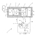
- FIGURE shows a schematic diagram of a hydraulic system with an arrangement of a high-pressure fluid chamber and a low-pressure fluid chamber in a housing of a double-piston accumulator in principle and not to scale.
- a hydraulic system 1 for a work machine for example in the form of a construction machine.
- the hydraulic system 1 in particular its pressure medium pump 2 is driven by a motor unit, not shown internal combustion engine, for example in the form of a diesel engine, with a predeterminable effective drive power.
- the pressure medium pump 2 is reversible in its conveying direction and variably adjustable in its delivery volume.
- the pressure medium pump 2 selectively delivers from a low-pressure fluid chamber 5 (ND) of a double-piston accumulator 6 into a high-pressure fluid chamber 7 (HD) a pressure medium 3 via a fluid-conducting connection 4.
- the pertinent double piston accumulator 6 has a designated as a whole with 16 housing.
- the housing 16 is in the form of a cylinder tube, but may also have other cross-sectional shapes.
- two longitudinally movable pistons 13, 17 are arranged, which are fixedly connected to each other via a coupling element 18 in the form of a coupling rod 19.
- the coupling rod 19 in turn is moved longitudinally with the piston 13, 17 in a partition wall 20 of the housing 16.
- the partition is in the manner of a cylindrical intermediate portion of the housing 16 trained.
- the partition wall 20 with the adjacent opposing pistons 13, 17 defines two fluid spaces in the form of low-pressure fluid chamber 5 and in the form of the high-pressure fluid chamber 7.
- the partition wall 20 corresponding sealing systems, not shown on.
- the housing 16 is delimited by two end walls 21, 22, which form the closure cover of the double-piston accumulator 6. Between the viewed in the direction of the figure left end wall 21 and the adjacent opposite piston 13 is bounded by these parts, a biasing chamber 14 with variable volume, which is a predetermined internal gas pressure via a connection point 23 of a pressure vessel 15 impressed.
- the pressure vessel 15 is preferably designed as a nitrogen storage of conventional design.
- the gas (N 2 ) with prescribable gas pressure located in the preload space 14 forms a type of gas or pressure cushion.
- the opposite piston 17 defines together with the end wall 22 an ambient space 24, which preferably has the respective ambient pressure. In the surrounding space 24, however, another working gas could also be used in a non-illustrated embodiment of the solution according to the invention, such as the nitrogen (N 2 ) mentioned in the prestressing space 14.
- the ambient space 24 is connected via a leak oil line 26 with a pressure medium container 10 (tank) for the purpose of removing leakage oil of the double piston accumulator 6. Furthermore, an accumulator 11 acts on the first fluid-conducting connection 4, which leads from the low-pressure fluid chamber 5 to the pressure medium pump 2. The fluid pressure in the first fluid-conducting connection 4 also serves to act on a pilot control device 12 for influencing the flow rate and the conveying direction of the pressure medium pump 2.
- the volume of the low-pressure fluid chamber 5 is chosen to be much larger than the volume of the high-pressure fluid chamber 7, wherein in the embodiment shown, the inner diameter of the housing part with the low-pressure fluid chamber 5 is chosen to be much larger than that in the housing part of the high-pressure fluid chamber. 7 the case is. In this way, sufficient stored pressure medium, provided for the operation of the hydraulic system 1, so that the pressure medium pump 2 can be supplied safely and permanently with pressure medium even with external or internal leakage volume flows.
- a check valve 8 is provided in the second fluid-carrying connection 9, at a point between the pressure medium tank 10 (tank) and a node 25 between the pressure accumulator 11 and the pressure medium pump second If the low-pressure fluid chamber 5 is undersupplied with the pressure medium, it is possible that pressure medium is sucked in from the pressure medium container 10 via the non-return valve 8 which opens toward the pressure medium pump 2 and supplied to the pressure medium pump 2 under the pretension pressure of the pressure accumulator 11. In this way, a prestressed pressure medium supply to the pressure medium pump 2 is twice possible. In particular, pressure medium 3 is then sucked in from the pressure medium container 10 via the check valve 8 when the pressure medium pump 2 is accelerated and pressure medium is conveyed from the low-pressure fluid space 5 into the high-pressure fluid space 7.
- the double-piston accumulator 6 makes it possible to bias pressure medium 3 flowing as a connecting link from and to the pressure medium pump 2.
- the volume on the low pressure side, that is, in the low pressure fluid space 5, is increased as the volume on the high pressure side, that is, in the high pressure fluid space 7, decreases.
- the double piston accumulator 6 is constructed substantially symmetrically with respect to its longitudinal axis and center axis and thus structurally simple and inexpensive to produce.
Claims (5)
- Installation hydraulique, notamment pour un véhicule utilitaire, comme un engin de chantier, comprenant une pompe (2) à fluide sous pression, dont le sens de refoulement peut être inversé et dont le volume de refoulement peut être réglé de façon variable, dans laquelle la pompe (2) à fluide sous pression prélève le fluide (3) sous pression, par une première liaison (4) fluidique, d'une chambre (5) de fluide basse pression d'un accumulateur (6) à double piston, et le refoule dans une chambre (7) de fluide haute pression de l'accumulateur (6) à double piston, qui est disposé entre la pompe (2) à fluide sous pression et l'utilisateur, et dans laquelle le volume de la chambre (5) de fluide basse pression est plus grand que le volume de la chambre (7) de fluide haute pression, caractérisée en ce que le fluide (3) sous pression sert dans la chambre (5) de fluide basse pression à l'alimentation d'un dispositif (12) de pilotage du volume de refoulement et du sens de refoulement de la pompe (2) à fluide sous pression.
- Installation hydraulique suivant la revendication 1, caractérisée en ce que la chambre (5) de fluide basse pression communique avec le réservoir (10) de fluide sous pression par une deuxième liaison (9) fluidique, par l'intermédiaire d'un clapet (8) antiretour s'ouvrant dans le sens allant vers la pompe (2) à fluide sous pression.
- Installation hydraulique suivant la revendication 1 ou 2, caractérisée en ce que la première ou la deuxième liaison (4, 9) fluidique communique avec un accumulateur (11) de fluide sous pression entre le clapet (8) antiretour et la pompe (2) à fluide sous pression.
- Installation hydraulique suivant l'une des revendications 1 à 3, caractérisée en ce qu'au moins un piston (13) de l'accumulateur (6) à double piston délimite une chambre (14) de prédétente, ayant une pression interne de gaz pouvant être donnée à l'avance et en ce que l'espace (14) de prédétente communique avec un réservoir (15) sous pression.
- Installation hydraulique suivant l'une des revendications précédentes, caractérisée en ce que la pompe (2) à fluide sous pression prélève le fluide (3) sous pression, par l'intermédiaire d'une première liaison (4) fluidique, d'une chambre (5) de fluide basse pression d'un accumulateur (6) à double piston, et le refoule dans une chambre (7) de fluide haute pression de l'accumulateur (6) à double piston, dont les volumes pour du fluide sont couplés mécaniquement.
Applications Claiming Priority (2)
| Application Number | Priority Date | Filing Date | Title |
|---|---|---|---|
| DE102010023016A DE102010023016A1 (de) | 2010-06-08 | 2010-06-08 | Hydraulische Anlage |
| PCT/EP2011/002642 WO2011154101A1 (fr) | 2010-06-08 | 2011-05-27 | Installation hydraulique |
Publications (2)
| Publication Number | Publication Date |
|---|---|
| EP2580080A1 EP2580080A1 (fr) | 2013-04-17 |
| EP2580080B1 true EP2580080B1 (fr) | 2014-08-27 |
Family
ID=44118838
Family Applications (1)
| Application Number | Title | Priority Date | Filing Date |
|---|---|---|---|
| EP11722019.4A Not-in-force EP2580080B1 (fr) | 2010-06-08 | 2011-05-27 | Installation hydraulique |
Country Status (3)
| Country | Link |
|---|---|
| EP (1) | EP2580080B1 (fr) |
| DE (1) | DE102010023016A1 (fr) |
| WO (1) | WO2011154101A1 (fr) |
Families Citing this family (3)
| Publication number | Priority date | Publication date | Assignee | Title |
|---|---|---|---|---|
| JP6208139B2 (ja) * | 2011-10-10 | 2017-10-04 | ロブソン, アンガス ピーターROBSON, Angus Peter | アキュムレータ |
| CN104564577A (zh) * | 2013-10-29 | 2015-04-29 | 北京精密机电控制设备研究所 | 一种伺服电动泵 |
| US11661960B2 (en) | 2020-03-27 | 2023-05-30 | Smc Corporation | Pressure-booster output stabilizer |
Family Cites Families (7)
| Publication number | Priority date | Publication date | Assignee | Title |
|---|---|---|---|---|
| US2286798A (en) * | 1940-05-16 | 1942-06-16 | Hydraulic Dev Corp Inc | Hydraulic circuit for press brakes |
| DE3829646A1 (de) * | 1988-09-01 | 1990-03-15 | Teves Gmbh Alfred | Reservoir fuer einen druckmittelkreis, insbesondere flugzeughydraulikkreis |
| FR2786442B1 (fr) * | 1998-12-01 | 2001-03-02 | Peugeot | Dispositif formant toit coulissant de vehicule automobile |
| AU3001502A (en) * | 2000-11-28 | 2002-06-11 | Ifield Technology Ltd | Hydraulic energy storage systems |
| AUPR170400A0 (en) * | 2000-11-28 | 2000-12-21 | Ifield Technology Ltd | Emergency energy release for hydraulic energy storage systems |
| DE102006048399B4 (de) * | 2006-10-12 | 2018-05-09 | Liebherr-Aerospace Lindenberg Gmbh | Vorrichtung zur Entriegelung eines Bauteils eines Flugzeuges |
| US7926501B2 (en) * | 2007-02-07 | 2011-04-19 | National Oilwell Varco L.P. | Subsea pressure systems for fluid recovery |
-
2010
- 2010-06-08 DE DE102010023016A patent/DE102010023016A1/de not_active Withdrawn
-
2011
- 2011-05-27 WO PCT/EP2011/002642 patent/WO2011154101A1/fr active Application Filing
- 2011-05-27 EP EP11722019.4A patent/EP2580080B1/fr not_active Not-in-force
Also Published As
| Publication number | Publication date |
|---|---|
| WO2011154101A1 (fr) | 2011-12-15 |
| DE102010023016A1 (de) | 2011-12-08 |
| EP2580080A1 (fr) | 2013-04-17 |
Similar Documents
| Publication | Publication Date | Title |
|---|---|---|
| EP2786025B1 (fr) | Système permettant d'améliorer le rendement énergétique de systèmes hydrauliques, et accumulateur à piston et accumulateur de pression destiné audit système | |
| EP2550170B1 (fr) | Système d'entraînement hybride hydrostatique | |
| DE3142604C2 (fr) | ||
| DE102011120227B4 (de) | Hydraulisches Hybridsystem für rotatorische Anwendungen | |
| DE102009008850B4 (de) | Variable Verdrängergetriebepumpe | |
| EP2307726B1 (fr) | Pompe à cylindrée variable | |
| DE10209880A1 (de) | System zur Steuerung einer hydraulischen Verstellpumpe | |
| EP2834542B1 (fr) | Circuit hydraulique fermé | |
| EP2251549B1 (fr) | Installation hydraulique | |
| EP2580080B1 (fr) | Installation hydraulique | |
| DE102007016145A1 (de) | Flügelzellenpumpe | |
| DE102012202904A1 (de) | Pumpenanordnung zum Erzeugen eines variablen Volumenstromes | |
| DE19527402A1 (de) | Pumpe | |
| EP1564414A1 (fr) | Dispositif de commande hydraulique | |
| DE102010023015B4 (de) | Hydraulische Anlage | |
| DE102011079311A1 (de) | Kühlmittelpumpe für einen Kühlmittelkreiskreislauf einer Brennkraftmaschine | |
| DE102009037198A1 (de) | Hydraulische Steueranordnung | |
| EP2342118B1 (fr) | Direction assistée hydraulique | |
| DE102010038863A1 (de) | Hydraulische Pumpe | |
| EP2157318A2 (fr) | Dispositif d'alimentation hydraulique | |
| DE4240590A1 (de) | Verdrängerpumpe | |
| EP2395242A1 (fr) | Système d'entraînement hydrostatique doté d'une pompe d'alimentation | |
| DE102006000832A1 (de) | Radialkolbenpumpe mit Fördermengenregelung | |
| DE3225196C2 (fr) | ||
| DE102021214704A1 (de) | Hydraulisches System |
Legal Events
| Date | Code | Title | Description |
|---|---|---|---|
| PUAI | Public reference made under article 153(3) epc to a published international application that has entered the european phase |
Free format text: ORIGINAL CODE: 0009012 |
|
| 17P | Request for examination filed |
Effective date: 20121109 |
|
| AK | Designated contracting states |
Kind code of ref document: A1 Designated state(s): AL AT BE BG CH CY CZ DE DK EE ES FI FR GB GR HR HU IE IS IT LI LT LU LV MC MK MT NL NO PL PT RO RS SE SI SK SM TR |
|
| DAX | Request for extension of the european patent (deleted) | ||
| REG | Reference to a national code |
Ref country code: DE Ref legal event code: R079 Ref document number: 502011004198 Country of ref document: DE Free format text: PREVIOUS MAIN CLASS: B60K0006120000 Ipc: E02F0009220000 |
|
| RIC1 | Information provided on ipc code assigned before grant |
Ipc: F15B 1/24 20060101ALI20140304BHEP Ipc: F15B 21/04 20060101ALI20140304BHEP Ipc: E02F 9/22 20060101AFI20140304BHEP Ipc: F15B 1/02 20060101ALI20140304BHEP |
|
| GRAP | Despatch of communication of intention to grant a patent |
Free format text: ORIGINAL CODE: EPIDOSNIGR1 |
|
| INTG | Intention to grant announced |
Effective date: 20140513 |
|
| GRAS | Grant fee paid |
Free format text: ORIGINAL CODE: EPIDOSNIGR3 |
|
| GRAA | (expected) grant |
Free format text: ORIGINAL CODE: 0009210 |
|
| AK | Designated contracting states |
Kind code of ref document: B1 Designated state(s): AL AT BE BG CH CY CZ DE DK EE ES FI FR GB GR HR HU IE IS IT LI LT LU LV MC MK MT NL NO PL PT RO RS SE SI SK SM TR |
|
| REG | Reference to a national code |
Ref country code: GB Ref legal event code: FG4D Free format text: NOT ENGLISH |
|
| REG | Reference to a national code |
Ref country code: CH Ref legal event code: EP |
|
| REG | Reference to a national code |
Ref country code: AT Ref legal event code: REF Ref document number: 684616 Country of ref document: AT Kind code of ref document: T Effective date: 20140915 |
|
| REG | Reference to a national code |
Ref country code: IE Ref legal event code: FG4D Free format text: LANGUAGE OF EP DOCUMENT: GERMAN |
|
| REG | Reference to a national code |
Ref country code: DE Ref legal event code: R096 Ref document number: 502011004198 Country of ref document: DE Effective date: 20141009 |
|
| REG | Reference to a national code |
Ref country code: SE Ref legal event code: TRGR |
|
| REG | Reference to a national code |
Ref country code: LT Ref legal event code: MG4D |
|
| REG | Reference to a national code |
Ref country code: NL Ref legal event code: VDEP Effective date: 20140827 |
|
| PG25 | Lapsed in a contracting state [announced via postgrant information from national office to epo] |
Ref country code: PT Free format text: LAPSE BECAUSE OF FAILURE TO SUBMIT A TRANSLATION OF THE DESCRIPTION OR TO PAY THE FEE WITHIN THE PRESCRIBED TIME-LIMIT Effective date: 20141229 Ref country code: BG Free format text: LAPSE BECAUSE OF FAILURE TO SUBMIT A TRANSLATION OF THE DESCRIPTION OR TO PAY THE FEE WITHIN THE PRESCRIBED TIME-LIMIT Effective date: 20141127 Ref country code: NO Free format text: LAPSE BECAUSE OF FAILURE TO SUBMIT A TRANSLATION OF THE DESCRIPTION OR TO PAY THE FEE WITHIN THE PRESCRIBED TIME-LIMIT Effective date: 20141127 Ref country code: FI Free format text: LAPSE BECAUSE OF FAILURE TO SUBMIT A TRANSLATION OF THE DESCRIPTION OR TO PAY THE FEE WITHIN THE PRESCRIBED TIME-LIMIT Effective date: 20140827 Ref country code: GR Free format text: LAPSE BECAUSE OF FAILURE TO SUBMIT A TRANSLATION OF THE DESCRIPTION OR TO PAY THE FEE WITHIN THE PRESCRIBED TIME-LIMIT Effective date: 20141128 Ref country code: LT Free format text: LAPSE BECAUSE OF FAILURE TO SUBMIT A TRANSLATION OF THE DESCRIPTION OR TO PAY THE FEE WITHIN THE PRESCRIBED TIME-LIMIT Effective date: 20140827 Ref country code: ES Free format text: LAPSE BECAUSE OF FAILURE TO SUBMIT A TRANSLATION OF THE DESCRIPTION OR TO PAY THE FEE WITHIN THE PRESCRIBED TIME-LIMIT Effective date: 20140827 |
|
| PG25 | Lapsed in a contracting state [announced via postgrant information from national office to epo] |
Ref country code: HR Free format text: LAPSE BECAUSE OF FAILURE TO SUBMIT A TRANSLATION OF THE DESCRIPTION OR TO PAY THE FEE WITHIN THE PRESCRIBED TIME-LIMIT Effective date: 20140827 Ref country code: IS Free format text: LAPSE BECAUSE OF FAILURE TO SUBMIT A TRANSLATION OF THE DESCRIPTION OR TO PAY THE FEE WITHIN THE PRESCRIBED TIME-LIMIT Effective date: 20141227 Ref country code: CY Free format text: LAPSE BECAUSE OF FAILURE TO SUBMIT A TRANSLATION OF THE DESCRIPTION OR TO PAY THE FEE WITHIN THE PRESCRIBED TIME-LIMIT Effective date: 20140827 Ref country code: RS Free format text: LAPSE BECAUSE OF FAILURE TO SUBMIT A TRANSLATION OF THE DESCRIPTION OR TO PAY THE FEE WITHIN THE PRESCRIBED TIME-LIMIT Effective date: 20140827 Ref country code: LV Free format text: LAPSE BECAUSE OF FAILURE TO SUBMIT A TRANSLATION OF THE DESCRIPTION OR TO PAY THE FEE WITHIN THE PRESCRIBED TIME-LIMIT Effective date: 20140827 |
|
| PG25 | Lapsed in a contracting state [announced via postgrant information from national office to epo] |
Ref country code: NL Free format text: LAPSE BECAUSE OF FAILURE TO SUBMIT A TRANSLATION OF THE DESCRIPTION OR TO PAY THE FEE WITHIN THE PRESCRIBED TIME-LIMIT Effective date: 20140827 |
|
| PG25 | Lapsed in a contracting state [announced via postgrant information from national office to epo] |
Ref country code: RO Free format text: LAPSE BECAUSE OF FAILURE TO SUBMIT A TRANSLATION OF THE DESCRIPTION OR TO PAY THE FEE WITHIN THE PRESCRIBED TIME-LIMIT Effective date: 20140827 Ref country code: CZ Free format text: LAPSE BECAUSE OF FAILURE TO SUBMIT A TRANSLATION OF THE DESCRIPTION OR TO PAY THE FEE WITHIN THE PRESCRIBED TIME-LIMIT Effective date: 20140827 Ref country code: SK Free format text: LAPSE BECAUSE OF FAILURE TO SUBMIT A TRANSLATION OF THE DESCRIPTION OR TO PAY THE FEE WITHIN THE PRESCRIBED TIME-LIMIT Effective date: 20140827 Ref country code: EE Free format text: LAPSE BECAUSE OF FAILURE TO SUBMIT A TRANSLATION OF THE DESCRIPTION OR TO PAY THE FEE WITHIN THE PRESCRIBED TIME-LIMIT Effective date: 20140827 Ref country code: DK Free format text: LAPSE BECAUSE OF FAILURE TO SUBMIT A TRANSLATION OF THE DESCRIPTION OR TO PAY THE FEE WITHIN THE PRESCRIBED TIME-LIMIT Effective date: 20140827 |
|
| REG | Reference to a national code |
Ref country code: DE Ref legal event code: R097 Ref document number: 502011004198 Country of ref document: DE |
|
| PG25 | Lapsed in a contracting state [announced via postgrant information from national office to epo] |
Ref country code: PL Free format text: LAPSE BECAUSE OF FAILURE TO SUBMIT A TRANSLATION OF THE DESCRIPTION OR TO PAY THE FEE WITHIN THE PRESCRIBED TIME-LIMIT Effective date: 20140827 |
|
| PLBE | No opposition filed within time limit |
Free format text: ORIGINAL CODE: 0009261 |
|
| STAA | Information on the status of an ep patent application or granted ep patent |
Free format text: STATUS: NO OPPOSITION FILED WITHIN TIME LIMIT |
|
| 26N | No opposition filed |
Effective date: 20150528 |
|
| PG25 | Lapsed in a contracting state [announced via postgrant information from national office to epo] |
Ref country code: SI Free format text: LAPSE BECAUSE OF FAILURE TO SUBMIT A TRANSLATION OF THE DESCRIPTION OR TO PAY THE FEE WITHIN THE PRESCRIBED TIME-LIMIT Effective date: 20140827 |
|
| REG | Reference to a national code |
Ref country code: CH Ref legal event code: PL |
|
| GBPC | Gb: european patent ceased through non-payment of renewal fee |
Effective date: 20150527 |
|
| PG25 | Lapsed in a contracting state [announced via postgrant information from national office to epo] |
Ref country code: CH Free format text: LAPSE BECAUSE OF NON-PAYMENT OF DUE FEES Effective date: 20150531 Ref country code: LI Free format text: LAPSE BECAUSE OF NON-PAYMENT OF DUE FEES Effective date: 20150531 Ref country code: MC Free format text: LAPSE BECAUSE OF FAILURE TO SUBMIT A TRANSLATION OF THE DESCRIPTION OR TO PAY THE FEE WITHIN THE PRESCRIBED TIME-LIMIT Effective date: 20140827 Ref country code: LU Free format text: LAPSE BECAUSE OF FAILURE TO SUBMIT A TRANSLATION OF THE DESCRIPTION OR TO PAY THE FEE WITHIN THE PRESCRIBED TIME-LIMIT Effective date: 20150527 |
|
| REG | Reference to a national code |
Ref country code: IE Ref legal event code: MM4A |
|
| REG | Reference to a national code |
Ref country code: FR Ref legal event code: PLFP Year of fee payment: 6 |
|
| PG25 | Lapsed in a contracting state [announced via postgrant information from national office to epo] |
Ref country code: IE Free format text: LAPSE BECAUSE OF NON-PAYMENT OF DUE FEES Effective date: 20150527 Ref country code: GB Free format text: LAPSE BECAUSE OF NON-PAYMENT OF DUE FEES Effective date: 20150527 |
|
| PG25 | Lapsed in a contracting state [announced via postgrant information from national office to epo] |
Ref country code: MT Free format text: LAPSE BECAUSE OF FAILURE TO SUBMIT A TRANSLATION OF THE DESCRIPTION OR TO PAY THE FEE WITHIN THE PRESCRIBED TIME-LIMIT Effective date: 20140827 |
|
| REG | Reference to a national code |
Ref country code: FR Ref legal event code: PLFP Year of fee payment: 7 |
|
| PG25 | Lapsed in a contracting state [announced via postgrant information from national office to epo] |
Ref country code: HU Free format text: LAPSE BECAUSE OF FAILURE TO SUBMIT A TRANSLATION OF THE DESCRIPTION OR TO PAY THE FEE WITHIN THE PRESCRIBED TIME-LIMIT; INVALID AB INITIO Effective date: 20110527 Ref country code: SM Free format text: LAPSE BECAUSE OF FAILURE TO SUBMIT A TRANSLATION OF THE DESCRIPTION OR TO PAY THE FEE WITHIN THE PRESCRIBED TIME-LIMIT Effective date: 20140827 |
|
| REG | Reference to a national code |
Ref country code: AT Ref legal event code: MM01 Ref document number: 684616 Country of ref document: AT Kind code of ref document: T Effective date: 20160527 |
|
| PG25 | Lapsed in a contracting state [announced via postgrant information from national office to epo] |
Ref country code: BE Free format text: LAPSE BECAUSE OF NON-PAYMENT OF DUE FEES Effective date: 20150531 |
|
| PG25 | Lapsed in a contracting state [announced via postgrant information from national office to epo] |
Ref country code: TR Free format text: LAPSE BECAUSE OF FAILURE TO SUBMIT A TRANSLATION OF THE DESCRIPTION OR TO PAY THE FEE WITHIN THE PRESCRIBED TIME-LIMIT Effective date: 20140827 Ref country code: AT Free format text: LAPSE BECAUSE OF NON-PAYMENT OF DUE FEES Effective date: 20160527 |
|
| REG | Reference to a national code |
Ref country code: FR Ref legal event code: PLFP Year of fee payment: 8 |
|
| PG25 | Lapsed in a contracting state [announced via postgrant information from national office to epo] |
Ref country code: MK Free format text: LAPSE BECAUSE OF FAILURE TO SUBMIT A TRANSLATION OF THE DESCRIPTION OR TO PAY THE FEE WITHIN THE PRESCRIBED TIME-LIMIT Effective date: 20140827 |
|
| PGFP | Annual fee paid to national office [announced via postgrant information from national office to epo] |
Ref country code: DE Payment date: 20180531 Year of fee payment: 8 |
|
| PGFP | Annual fee paid to national office [announced via postgrant information from national office to epo] |
Ref country code: IT Payment date: 20180514 Year of fee payment: 8 Ref country code: FR Payment date: 20180404 Year of fee payment: 8 |
|
| PGFP | Annual fee paid to national office [announced via postgrant information from national office to epo] |
Ref country code: SE Payment date: 20180404 Year of fee payment: 8 |
|
| PG25 | Lapsed in a contracting state [announced via postgrant information from national office to epo] |
Ref country code: AL Free format text: LAPSE BECAUSE OF FAILURE TO SUBMIT A TRANSLATION OF THE DESCRIPTION OR TO PAY THE FEE WITHIN THE PRESCRIBED TIME-LIMIT Effective date: 20140827 |
|
| REG | Reference to a national code |
Ref country code: DE Ref legal event code: R119 Ref document number: 502011004198 Country of ref document: DE |
|
| PG25 | Lapsed in a contracting state [announced via postgrant information from national office to epo] |
Ref country code: SE Free format text: LAPSE BECAUSE OF NON-PAYMENT OF DUE FEES Effective date: 20190528 |
|
| PG25 | Lapsed in a contracting state [announced via postgrant information from national office to epo] |
Ref country code: DE Free format text: LAPSE BECAUSE OF NON-PAYMENT OF DUE FEES Effective date: 20191203 Ref country code: IT Free format text: LAPSE BECAUSE OF NON-PAYMENT OF DUE FEES Effective date: 20190527 |
|
| REG | Reference to a national code |
Ref country code: SE Ref legal event code: EUG |
|
| PG25 | Lapsed in a contracting state [announced via postgrant information from national office to epo] |
Ref country code: FR Free format text: LAPSE BECAUSE OF NON-PAYMENT OF DUE FEES Effective date: 20190531 |