EP2578547A2 - Systèmes et procédés de fabrication de verre à combustion immergée - Google Patents
Systèmes et procédés de fabrication de verre à combustion immergée Download PDFInfo
- Publication number
- EP2578547A2 EP2578547A2 EP12006919.0A EP12006919A EP2578547A2 EP 2578547 A2 EP2578547 A2 EP 2578547A2 EP 12006919 A EP12006919 A EP 12006919A EP 2578547 A2 EP2578547 A2 EP 2578547A2
- Authority
- EP
- European Patent Office
- Prior art keywords
- exhaust
- melter
- barrier
- roof
- floor
- Prior art date
- Legal status (The legal status is an assumption and is not a legal conclusion. Google has not performed a legal analysis and makes no representation as to the accuracy of the status listed.)
- Granted
Links
- 238000002485 combustion reaction Methods 0.000 title claims abstract description 127
- 239000011521 glass Substances 0.000 title claims abstract description 34
- 238000004519 manufacturing process Methods 0.000 title claims abstract description 16
- 238000000034 method Methods 0.000 title claims description 57
- 239000000463 material Substances 0.000 claims abstract description 115
- 230000004888 barrier function Effects 0.000 claims abstract description 63
- 238000009833 condensation Methods 0.000 claims abstract description 9
- 230000005494 condensation Effects 0.000 claims abstract description 9
- 238000007599 discharging Methods 0.000 claims abstract description 9
- 239000000446 fuel Substances 0.000 claims description 46
- 239000012530 fluid Substances 0.000 claims description 35
- 229910052751 metal Inorganic materials 0.000 claims description 34
- 239000002184 metal Substances 0.000 claims description 34
- 239000007788 liquid Substances 0.000 claims description 22
- 230000007704 transition Effects 0.000 claims description 19
- 238000002844 melting Methods 0.000 claims description 17
- 230000008018 melting Effects 0.000 claims description 17
- 239000006060 molten glass Substances 0.000 claims description 17
- 238000007496 glass forming Methods 0.000 claims description 16
- 238000001816 cooling Methods 0.000 claims description 14
- 239000007789 gas Substances 0.000 claims description 11
- 229910001026 inconel Inorganic materials 0.000 claims description 11
- 229910000831 Steel Inorganic materials 0.000 claims description 5
- 239000010959 steel Substances 0.000 claims description 5
- XLYOFNOQVPJJNP-UHFFFAOYSA-N water Substances O XLYOFNOQVPJJNP-UHFFFAOYSA-N 0.000 claims description 5
- 238000009841 combustion method Methods 0.000 claims description 2
- 239000003570 air Substances 0.000 description 38
- 239000007800 oxidant agent Substances 0.000 description 29
- 230000001590 oxidative effect Effects 0.000 description 22
- 239000000203 mixture Substances 0.000 description 19
- 239000000155 melt Substances 0.000 description 15
- QVGXLLKOCUKJST-UHFFFAOYSA-N atomic oxygen Chemical compound [O] QVGXLLKOCUKJST-UHFFFAOYSA-N 0.000 description 11
- 239000001301 oxygen Substances 0.000 description 11
- 229910052760 oxygen Inorganic materials 0.000 description 11
- 230000008569 process Effects 0.000 description 11
- VNWKTOKETHGBQD-UHFFFAOYSA-N methane Chemical compound C VNWKTOKETHGBQD-UHFFFAOYSA-N 0.000 description 10
- 238000012546 transfer Methods 0.000 description 9
- 230000006870 function Effects 0.000 description 8
- 238000013461 design Methods 0.000 description 7
- IJGRMHOSHXDMSA-UHFFFAOYSA-N Atomic nitrogen Chemical compound N#N IJGRMHOSHXDMSA-UHFFFAOYSA-N 0.000 description 6
- 238000012986 modification Methods 0.000 description 6
- 230000004048 modification Effects 0.000 description 6
- 239000007787 solid Substances 0.000 description 5
- CURLTUGMZLYLDI-UHFFFAOYSA-N Carbon dioxide Chemical compound O=C=O CURLTUGMZLYLDI-UHFFFAOYSA-N 0.000 description 4
- ATUOYWHBWRKTHZ-UHFFFAOYSA-N Propane Chemical compound CCC ATUOYWHBWRKTHZ-UHFFFAOYSA-N 0.000 description 4
- MCMNRKCIXSYSNV-UHFFFAOYSA-N Zirconium dioxide Chemical compound O=[Zr]=O MCMNRKCIXSYSNV-UHFFFAOYSA-N 0.000 description 4
- 239000000567 combustion gas Substances 0.000 description 4
- 238000005259 measurement Methods 0.000 description 4
- 239000012768 molten material Substances 0.000 description 4
- 229910001220 stainless steel Inorganic materials 0.000 description 4
- 239000011800 void material Substances 0.000 description 4
- 229910000975 Carbon steel Inorganic materials 0.000 description 3
- 239000010962 carbon steel Substances 0.000 description 3
- 239000000919 ceramic Substances 0.000 description 3
- 239000006063 cullet Substances 0.000 description 3
- 238000010586 diagram Methods 0.000 description 3
- 230000000694 effects Effects 0.000 description 3
- 238000010438 heat treatment Methods 0.000 description 3
- 230000003993 interaction Effects 0.000 description 3
- 239000003345 natural gas Substances 0.000 description 3
- 229910052757 nitrogen Inorganic materials 0.000 description 3
- 239000003921 oil Substances 0.000 description 3
- 230000010355 oscillation Effects 0.000 description 3
- 238000001179 sorption measurement Methods 0.000 description 3
- 241000894007 species Species 0.000 description 3
- XKRFYHLGVUSROY-UHFFFAOYSA-N Argon Chemical compound [Ar] XKRFYHLGVUSROY-UHFFFAOYSA-N 0.000 description 2
- OKTJSMMVPCPJKN-UHFFFAOYSA-N Carbon Chemical compound [C] OKTJSMMVPCPJKN-UHFFFAOYSA-N 0.000 description 2
- UGFAIRIUMAVXCW-UHFFFAOYSA-N Carbon monoxide Chemical compound [O+]#[C-] UGFAIRIUMAVXCW-UHFFFAOYSA-N 0.000 description 2
- MYMOFIZGZYHOMD-UHFFFAOYSA-N Dioxygen Chemical compound O=O MYMOFIZGZYHOMD-UHFFFAOYSA-N 0.000 description 2
- LYCAIKOWRPUZTN-UHFFFAOYSA-N Ethylene glycol Chemical compound OCCO LYCAIKOWRPUZTN-UHFFFAOYSA-N 0.000 description 2
- 230000003044 adaptive effect Effects 0.000 description 2
- 239000012080 ambient air Substances 0.000 description 2
- 239000011230 binding agent Substances 0.000 description 2
- 230000015572 biosynthetic process Effects 0.000 description 2
- 229910052799 carbon Inorganic materials 0.000 description 2
- 239000001569 carbon dioxide Substances 0.000 description 2
- 229910002092 carbon dioxide Inorganic materials 0.000 description 2
- 229910002091 carbon monoxide Inorganic materials 0.000 description 2
- 238000004891 communication Methods 0.000 description 2
- 239000004567 concrete Substances 0.000 description 2
- 238000005520 cutting process Methods 0.000 description 2
- 239000006066 glass batch Substances 0.000 description 2
- 239000013529 heat transfer fluid Substances 0.000 description 2
- 239000001257 hydrogen Substances 0.000 description 2
- 229910052739 hydrogen Inorganic materials 0.000 description 2
- 239000011261 inert gas Substances 0.000 description 2
- 238000002347 injection Methods 0.000 description 2
- 239000007924 injection Substances 0.000 description 2
- 239000003949 liquefied natural gas Substances 0.000 description 2
- 230000007246 mechanism Effects 0.000 description 2
- 239000012528 membrane Substances 0.000 description 2
- 150000002739 metals Chemical class 0.000 description 2
- 238000002156 mixing Methods 0.000 description 2
- 239000001294 propane Substances 0.000 description 2
- 239000011819 refractory material Substances 0.000 description 2
- 230000004044 response Effects 0.000 description 2
- 238000000926 separation method Methods 0.000 description 2
- 239000003381 stabilizer Substances 0.000 description 2
- 239000010935 stainless steel Substances 0.000 description 2
- 238000003860 storage Methods 0.000 description 2
- 229910000838 Al alloy Inorganic materials 0.000 description 1
- UFHFLCQGNIYNRP-UHFFFAOYSA-N Hydrogen Chemical compound [H][H] UFHFLCQGNIYNRP-UHFFFAOYSA-N 0.000 description 1
- NINIDFKCEFEMDL-UHFFFAOYSA-N Sulfur Chemical compound [S] NINIDFKCEFEMDL-UHFFFAOYSA-N 0.000 description 1
- 229910001069 Ti alloy Inorganic materials 0.000 description 1
- PNEYBMLMFCGWSK-UHFFFAOYSA-N aluminium oxide Inorganic materials [O-2].[O-2].[O-2].[Al+3].[Al+3] PNEYBMLMFCGWSK-UHFFFAOYSA-N 0.000 description 1
- 230000003466 anti-cipated effect Effects 0.000 description 1
- 229910052786 argon Inorganic materials 0.000 description 1
- 230000008901 benefit Effects 0.000 description 1
- 239000005388 borosilicate glass Substances 0.000 description 1
- 239000002419 bulk glass Substances 0.000 description 1
- 239000003575 carbonaceous material Substances 0.000 description 1
- 238000005266 casting Methods 0.000 description 1
- 238000010276 construction Methods 0.000 description 1
- 238000011109 contamination Methods 0.000 description 1
- 239000000110 cooling liquid Substances 0.000 description 1
- 238000011161 development Methods 0.000 description 1
- 230000008030 elimination Effects 0.000 description 1
- 238000003379 elimination reaction Methods 0.000 description 1
- 239000002360 explosive Substances 0.000 description 1
- 238000010304 firing Methods 0.000 description 1
- 230000009969 flowable effect Effects 0.000 description 1
- -1 fluoro- Chemical class 0.000 description 1
- 239000011494 foam glass Substances 0.000 description 1
- 238000009472 formulation Methods 0.000 description 1
- 238000007710 freezing Methods 0.000 description 1
- 230000008014 freezing Effects 0.000 description 1
- 239000002737 fuel gas Substances 0.000 description 1
- 239000008246 gaseous mixture Substances 0.000 description 1
- 239000003365 glass fiber Substances 0.000 description 1
- 239000000156 glass melt Substances 0.000 description 1
- 239000001307 helium Substances 0.000 description 1
- 229910052734 helium Inorganic materials 0.000 description 1
- SWQJXJOGLNCZEY-UHFFFAOYSA-N helium atom Chemical compound [He] SWQJXJOGLNCZEY-UHFFFAOYSA-N 0.000 description 1
- WMIYKQLTONQJES-UHFFFAOYSA-N hexafluoroethane Chemical compound FC(F)(F)C(F)(F)F WMIYKQLTONQJES-UHFFFAOYSA-N 0.000 description 1
- 150000002431 hydrogen Chemical class 0.000 description 1
- WGCNASOHLSPBMP-UHFFFAOYSA-N hydroxyacetaldehyde Natural products OCC=O WGCNASOHLSPBMP-UHFFFAOYSA-N 0.000 description 1
- 230000006872 improvement Effects 0.000 description 1
- 229910001872 inorganic gas Inorganic materials 0.000 description 1
- 229910052500 inorganic mineral Inorganic materials 0.000 description 1
- 238000009413 insulation Methods 0.000 description 1
- 239000007791 liquid phase Substances 0.000 description 1
- 230000013011 mating Effects 0.000 description 1
- 239000011707 mineral Substances 0.000 description 1
- 238000012544 monitoring process Methods 0.000 description 1
- 238000005457 optimization Methods 0.000 description 1
- 230000003647 oxidation Effects 0.000 description 1
- 238000007254 oxidation reaction Methods 0.000 description 1
- 239000002245 particle Substances 0.000 description 1
- 239000011236 particulate material Substances 0.000 description 1
- 238000005192 partition Methods 0.000 description 1
- 230000002093 peripheral effect Effects 0.000 description 1
- 238000004886 process control Methods 0.000 description 1
- 238000012545 processing Methods 0.000 description 1
- 230000010349 pulsation Effects 0.000 description 1
- 230000009467 reduction Effects 0.000 description 1
- 238000009420 retrofitting Methods 0.000 description 1
- 238000012552 review Methods 0.000 description 1
- 230000000630 rising effect Effects 0.000 description 1
- 239000012266 salt solution Substances 0.000 description 1
- VYPSYNLAJGMNEJ-UHFFFAOYSA-N silicon dioxide Inorganic materials O=[Si]=O VYPSYNLAJGMNEJ-UHFFFAOYSA-N 0.000 description 1
- 239000000377 silicon dioxide Substances 0.000 description 1
- 239000002002 slurry Substances 0.000 description 1
- 239000005361 soda-lime glass Substances 0.000 description 1
- 239000000243 solution Substances 0.000 description 1
- 239000004071 soot Substances 0.000 description 1
- 239000007858 starting material Substances 0.000 description 1
- 239000004575 stone Substances 0.000 description 1
- 229910052717 sulfur Inorganic materials 0.000 description 1
- 239000011593 sulfur Substances 0.000 description 1
- 238000012360 testing method Methods 0.000 description 1
- BFKJFAAPBSQJPD-UHFFFAOYSA-N tetrafluoroethene Chemical group FC(F)=C(F)F BFKJFAAPBSQJPD-UHFFFAOYSA-N 0.000 description 1
- TXEYQDLBPFQVAA-UHFFFAOYSA-N tetrafluoromethane Chemical compound FC(F)(F)F TXEYQDLBPFQVAA-UHFFFAOYSA-N 0.000 description 1
- 230000036962 time dependent Effects 0.000 description 1
- 239000002699 waste material Substances 0.000 description 1
- 238000003466 welding Methods 0.000 description 1
- 210000002268 wool Anatomy 0.000 description 1
Images


Classifications
-
- C—CHEMISTRY; METALLURGY
- C03—GLASS; MINERAL OR SLAG WOOL
- C03B—MANUFACTURE, SHAPING, OR SUPPLEMENTARY PROCESSES
- C03B5/00—Melting in furnaces; Furnaces so far as specially adapted for glass manufacture
- C03B5/16—Special features of the melting process; Auxiliary means specially adapted for glass-melting furnaces
- C03B5/167—Means for preventing damage to equipment, e.g. by molten glass, hot gases, batches
-
- C—CHEMISTRY; METALLURGY
- C03—GLASS; MINERAL OR SLAG WOOL
- C03B—MANUFACTURE, SHAPING, OR SUPPLEMENTARY PROCESSES
- C03B5/00—Melting in furnaces; Furnaces so far as specially adapted for glass manufacture
- C03B5/16—Special features of the melting process; Auxiliary means specially adapted for glass-melting furnaces
- C03B5/18—Stirring devices; Homogenisation
- C03B5/183—Stirring devices; Homogenisation using thermal means, e.g. for creating convection currents
-
- C—CHEMISTRY; METALLURGY
- C03—GLASS; MINERAL OR SLAG WOOL
- C03B—MANUFACTURE, SHAPING, OR SUPPLEMENTARY PROCESSES
- C03B5/00—Melting in furnaces; Furnaces so far as specially adapted for glass manufacture
- C03B5/16—Special features of the melting process; Auxiliary means specially adapted for glass-melting furnaces
- C03B5/18—Stirring devices; Homogenisation
- C03B5/193—Stirring devices; Homogenisation using gas, e.g. bubblers
-
- C—CHEMISTRY; METALLURGY
- C03—GLASS; MINERAL OR SLAG WOOL
- C03B—MANUFACTURE, SHAPING, OR SUPPLEMENTARY PROCESSES
- C03B5/00—Melting in furnaces; Furnaces so far as specially adapted for glass manufacture
- C03B5/16—Special features of the melting process; Auxiliary means specially adapted for glass-melting furnaces
- C03B5/235—Heating the glass
- C03B5/2353—Heating the glass by combustion with pure oxygen or oxygen-enriched air, e.g. using oxy-fuel burners or oxygen lances
-
- C—CHEMISTRY; METALLURGY
- C03—GLASS; MINERAL OR SLAG WOOL
- C03B—MANUFACTURE, SHAPING, OR SUPPLEMENTARY PROCESSES
- C03B5/00—Melting in furnaces; Furnaces so far as specially adapted for glass manufacture
- C03B5/16—Special features of the melting process; Auxiliary means specially adapted for glass-melting furnaces
- C03B5/235—Heating the glass
- C03B5/2356—Submerged heating, e.g. by using heat pipes, hot gas or submerged combustion burners
-
- C—CHEMISTRY; METALLURGY
- C03—GLASS; MINERAL OR SLAG WOOL
- C03B—MANUFACTURE, SHAPING, OR SUPPLEMENTARY PROCESSES
- C03B5/00—Melting in furnaces; Furnaces so far as specially adapted for glass manufacture
- C03B5/16—Special features of the melting process; Auxiliary means specially adapted for glass-melting furnaces
- C03B5/235—Heating the glass
- C03B5/237—Regenerators or recuperators specially adapted for glass-melting furnaces
-
- C—CHEMISTRY; METALLURGY
- C03—GLASS; MINERAL OR SLAG WOOL
- C03B—MANUFACTURE, SHAPING, OR SUPPLEMENTARY PROCESSES
- C03B2211/00—Heating processes for glass melting in glass melting furnaces
- C03B2211/20—Submerged gas heating
- C03B2211/22—Submerged gas heating by direct combustion in the melt
-
- C—CHEMISTRY; METALLURGY
- C03—GLASS; MINERAL OR SLAG WOOL
- C03B—MANUFACTURE, SHAPING, OR SUPPLEMENTARY PROCESSES
- C03B2211/00—Heating processes for glass melting in glass melting furnaces
- C03B2211/20—Submerged gas heating
- C03B2211/22—Submerged gas heating by direct combustion in the melt
- C03B2211/23—Submerged gas heating by direct combustion in the melt using oxygen, i.e. pure oxygen or oxygen-enriched air
-
- C—CHEMISTRY; METALLURGY
- C03—GLASS; MINERAL OR SLAG WOOL
- C03B—MANUFACTURE, SHAPING, OR SUPPLEMENTARY PROCESSES
- C03B2211/00—Heating processes for glass melting in glass melting furnaces
- C03B2211/40—Heating processes for glass melting in glass melting furnaces using oxy-fuel burners
Definitions
- the present disclosure relates generally to the field of submerged combustion glass melters and methods of use.
- Submerged combustion melters are known for producing molten glass. Submerged combustion melters and their operation may cause exhaust pressure and exhaust volume fluctuations due to large bubbles of gas from submerged combustion burners, which may lead to batch (starting material) carryover and/or molten glass carryover into the melter exhaust. Carryover may lead to reduced exhaust flow or even in some circumstances plugging of the exhaust ducts.
- submerged combustion melters and methods of use are described that may allow reduction of melter pressure fluctuations and/or carryover.
- a first aspect of the disclosure is a submerged combustion glass manufacturing system comprising:
- a second aspect of the disclosure is a submerged combustion glass manufacturing system comprising:
- a third aspect of the disclosure is a method of manufacturing glass comprising:
- a fourth aspect of the disclosure is a method of manufacturing glass comprising:
- FIG. 1 is a schematic side-elevation view, partially in cross-section, of a prior art submerged combustion melter and system
- FIG. 2 is a schematic side-elevation view of a submerged combustion melter and system embodiment of the present disclosure
- FIG. 3 is a schematic end elevation view, partially in cross-section, of the submerged combustion melter and system embodiment of FIG. 2 ;
- FIGS. 4 and 4A are schematic perspective views of two other melter and system embodiments of the present disclosure.
- FIG. 5 is a schematic perspective view of a portion of the exhaust structure of the melter and system embodiment of FIG. 4 ;
- FIG. 6 is a schematic plan view of the structure illustrated in FIG. 5 ;
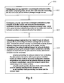
- FIGS. 7 and 8 are logic diagrams of two methods in accordance with the present disclosure.
- FIGS. 1-6 of the appended drawings may not be to scale and illustrate only typical embodiments of this disclosure, and are therefore not to be considered limiting of its scope, for the disclosure may admit to other equally effective embodiments.
- melters may suffer exhaust port plugging and/or reduced flow of exhaust, which may result in reduced or lost production, increased carryover of batch or cullet, and increased ejection of molten glass from the burners to the exhaust due to pulsation of combustion gases emanating from the burners.
- melters also frequently require a sump to catch debris falling off of the inside surfaces of the exhaust port.
- Submerged as used herein means that combustion gases emanate from burners under the level of the molten glass; the burners may be floor-mounted, wall-mounted, or in melter embodiments comprising more than one submerged combustion burner, any combination thereof (for example, two floor mounted burners and one wall mounted burner).
- combustion gases may be used interchangeably and mean substantially gaseous mixtures of any excess oxidant or fuel, oxides of carbon (such as carbon monoxide, carbon dioxide), oxides of nitrogen, oxides of sulfur, and water.
- Combustion products may include liquids and solids, for example soot and unburned liquid fuels.
- exhaust material includes all materials exiting the melter through an exhaust structure, and includes combustion gases, batch and/or cullet carryover, ejected molten glass, inspirated air, and the like.
- the phrase "the barrier configured to maintain temperature and pressure in the exhaust structure at values sufficient to substantially prevent condensation of exhaust material on the interior surface” essentially means determining the species in the exhaust material most likely to condense and maintaining the temperature and pressure at levels that would substantially prevent that species from condensing. For example, if the species most likely to condense would condense at 1500°F (815°C) or lower temperature and/or pressure less than 1 atmosphere, then the temperature of the interior surface of the barrier would be maintained at temperature slightly higher than 1500°F (for example 1520°C (826°C), or 1530°F (832°C), or higher) and pressure slightly above 1 atmosphere (for example, 1.1 atmosphere, 1.15 atmosphere, or higher).
- fuel means a combustible composition comprising a major portion of, for example, methane, natural gas, liquefied natural gas, propane, atomized oil or the like (either in gaseous or liquid form). Fuels useful in the disclosure may comprise minor amounts of non-fuels therein, including oxidants, for purposes such as premixing the fuel with the oxidant, or atomizing liquid fuels.
- fuel includes gaseous fuels, liquid fuels, flowable solids, such as powdered carbon or particulate material, waste materials, slurries, and mixtures or other combinations thereof.
- the gaseous fuel may be selected from the group consisting of methane, natural gas, liquefied natural gas, propane, carbon monoxide, hydrogen, steam-reformed natural gas, atomized oil or mixtures thereof.
- Oxidant means air, or compositions comprising the same molar concentration of oxygen as air, while the term “oxygen” means a gas with an oxygen molar concentration of at least 50%.
- oxidants include oxygen-enriched air containing at least 50% vol., oxygen such as "industrially” pure oxygen (99.5%) produced by a cryogenic air separation plant or non-pure oxygen produced by an adsorption process or membrane permeation process (about 90% vol. oxygen or more).
- the sources of oxidant and fuel may be one or more conduits, pipelines, storage facility, cylinders, or, in embodiments where the oxidant is air, ambient air.
- Oxygen-enriched oxidants may be supplied from a pipeline, cylinder, storage facility, cryogenic air separation unit, membrane permeation separator, or adsorption unit such as a vacuum swing adsorption unit.
- Submerged combustion melters useful in methods and systems of the present disclosure may be comprised of metal, ceramic, ceramic-lined metal, or combination thereof.
- Suitable metals include stainless steels, for example, but not limited to, 306 and 316 steel, as well as titanium alloys, aluminum alloys, carbon steel, and the like.
- One aspect of the disclosure is a submerged combustion glass manufacturing system comprising a melter comprising a floor, a roof, and a wall structure connecting the floor and roof, and an exhaust passage through the roof; one or more submerged combustion burners mounted in the floor and/or wall structure, the submerged combustion burners configured to discharge combustion products under a level of material being melted in the melter and create turbulent conditions in substantially all of the material; and an exhaust structure fluidly connecting the exhaust passage with an exhaust stack, the exhaust structure comprising a barrier preventing exhaust material from contacting the atmosphere, the barrier defining an exhaust chamber having an interior surface, the exhaust chamber having a cross-sectional area greater than that of the exhaust stack but less than the melter, the barrier configured to maintain temperature and pressure in the exhaust structure at values sufficient to substantially prevent condensation of exhaust material on the interior surface.
- Certain submerged combustion glass manufacturing systems may comprise more than one exhaust passage through the roof, and more than one exhaust structure as described herein.
- Certain systems of the present disclosure may comprise one or more feed inlets in a feed end of the wall structure, one or more molten glass outlets in an exit end of the wall structure, wherein the exhaust passage through the roof is positioned substantially centrally between the feed and exit ends.
- the exhaust passage and exhaust chamber may have a cross-sectional area at least large enough to allow non-turbulent flow of exhaust gases in the exhaust material flowing through the passage and chamber.
- the submerged combustion burners may be configured to discharge combustion products primarily non-laterally under the level of material being melted in the melter. In certain exemplary system and method embodiments the submerged combustion burners may be configured to discharge combustion products primarily vertically under the level of material being melted in the melter.
- the wall structure may comprise a feed end wall, an exit end wall, and two side walls, with each side wall connected to both the feed end wall and the exit end wall.
- the barrier of the exhaust structure may be constructed of materials selected from the group consisting of refractory, metal, and combinations thereof, with the proviso that if metal, the service temperature of the metal is higher than the temperature of the exhaust materials.
- suitable metals include, but are not limited to, carbon steel, stainless steels of various grades, Inconel, and the like.
- Certain systems embodiments may comprise a fluid-cooled transition structure fluidly connecting the exhaust passage and the exhaust structure.
- the fluid may be a liquid selected from the group consisting of water, organic liquids, inorganic liquids, and combinations thereof.
- Certain systems may comprise an air inspirator fluidly connecting the barrier and the exhaust stack.
- the air inspirator may comprise one or more adjustable panels.
- the air inspirator may comprise a hood or hoods that may be raised or lowered, for example using rails, guides, jack-screws or other sub-system. Movement may be accomplished using manual or automatic control, and may use electronic, pneumatic, or hydraulic actuation.
- the barrier of the exhaust structure may have a cross-sectional shape selected from the group consisting of rectangular, round, oval, trapezoidal, triangular, U-shaped, quadrangular, hexagonal, octagonal, parabolic.
- the cross-sectional shape of the barrier may be the same or different than the cross-sectional shape of the melter.
- the barrier of the exhaust structure may comprise a refractory lined metal layer wherein the refractory comprises the interior surface of the barrier, the metal layer having air-cooled surfaces that may also function as mechanical supports.
- the air-cooled surfaces may be fins, flow-through boxes, and the like, and may have channels, baffles, and other surfaces to increase or decrease heat transfer.
- the metal layer may be Inconel, and the air-cooled surfaces may be steel.
- the air-cooled surfaces or structures may be integral with the metal layer, or may be removably attached separate pieces, such as by bolted flange connections, welding, riveting, and similar attachment mechanisms.
- Another aspect of this disclosure are methods comprising melting glass-forming materials in a submerged combustion melter, the melter comprising a floor, a roof, and a wall structure connecting the floor and roof, and an exhaust passage through the roof; combusting a fuel in one or more submerged combustion burners mounted in the floor and/or wall structure, the submerged combustion burners discharging combustion products under a level of the glass-forming material being melted in the melter and creating turbulent conditions in substantially all of the material; and exhausting exhaust material from the melter through an exhaust structure fluidly connecting the exhaust passage with an exhaust stack, the exhaust structure comprising a barrier preventing the exhaust material from contacting the atmosphere, the barrier defining an exhaust chamber having an interior surface, the barrier configured to maintain temperature and pressure in the exhaust structure at values sufficient to substantially prevent the exhaust material from condensing on the interior surface.
- the exhaust passage may be substantially centrally located between a feed end and an exit end of the melter, and the exhausting of the exhaust material through the exhaust structure comprises exhausting the exhaust material substantially centrally between the feed end and the exit end of the melter.
- Certain method embodiments may comprise cooling the exhaust material prior to the exhaust chamber by flowing the exhaust material through a liquid-cooled transition structure fluidly connecting the exhaust passage and the barrier.
- Certain method embodiments may comprise inspiring air into the exhaust material through an air inspirator fluidly connecting the barrier and the exhaust stack. Certain methods may comprise adjusting one or more panels of the air inspirator, or moving the air inspirator up or down to let more or less air into the stack.
- At least some heat used for the melting may come from heat from combustion of at least some of the binder of glass mat and/or roving fed to the melter.
- the submerged combustion melter may be operated at a pressure less than atmospheric pressure.
- Certain system and method embodiments of this disclosure may include submerged combustion melters comprising fluid-cooled panels, such as described in assignee's co-pending U.S. patent application serial number 12/817754, filed June 17, 2010 .
- the submerged combustion melter may include one or more submerged combustion burners comprising one or more combustion burners such as described in assignee's co-pending U.S. patent application.
- burner combustion (flame) temperature may be controlled by monitoring one or more parameters selected from velocity of the fuel, velocity of the primary oxidant, mass and/or volume flow rate of the fuel, mass and/or volume flow rate of the primary oxidant, energy content of the fuel, temperature of the fuel as it enters the burner, temperature of the primary oxidant as it enters the burner, temperature of the effluent, pressure of the primary oxidant entering the burner, humidity of the oxidant, burner geometry, combustion ratio, and combinations thereof.
- Certain systems and processes of this disclosure may also measure and/or monitor feed rate of batch or other feed materials, such as glass mat or wound roving, mass of glass mat or wound roving per unit length, web or roving linear speed, and combinations thereof, and use these measurements for control purposes.
- feed rate of batch or other feed materials such as glass mat or wound roving, mass of glass mat or wound roving per unit length, web or roving linear speed, and combinations thereof, and use these measurements for control purposes.
- Exemplary systems and methods of the disclosure may comprise a combustion controller which receives one or more input parameters selected from velocity of the fuel, velocity of the primary oxidant, mass and/or volume flow rate of the fuel, mass and/or volume flow rate of the primary oxidant, energy content of the fuel, temperature of the fuel as it enters the burner, temperature of the primary oxidant as it enters the burner, pressure of the oxidant entering the burner, humidity of the oxidant, burner geometry, oxidation ratio, temperature of the effluent and combinations thereof, and employs a control algorithm to control combustion temperature based on one or more of these input parameters.
- Certain system and method embodiments may comprise using vibration and/or oscillation of the submerged combustion melter to predict melt viscosity and/or other properties of the initial melt emanating from the melter, as disclosed in assignee's co-pending U.S. patent application.
- FIG. 1 is a side-elevation view, partially in cross-section, of a prior art submerged combustion melter system and method embodiment 1, including a glass tank furnace or melter 10 positioned on a plant floor or other surface 2, including two burners 4 and 6.
- Melter 10 includes sidewalls 8 (an inlet end wall 8A and an outlet end wall 8B are illustrated), a floor 12, a roof 14, a may include a sump 15 for handling material that falls off the inside surfaces of an exhaust chute 16.
- Prior art melter and system embodiment 1 includes a molten glass melt exit 18.
- a glass-forming material feed bin 20 may be attached to melter sidewall 8 via a conduit 22, and FIG.
- melter 10 illustrates solid batch and/or cullet 23 entering melter 10, with a partially molten level of materials 24 indicated.
- Melt level 24 may be sensed by a level sensor 52.
- Melt 26 in melter 10 may be generally in a turbulent condition as indicated by flow-indicating arrows in melt 26, caused by combustion products 28 from burners 4, 6, although the prior art also includes melters having non-turbulent layers, such as when burners are positioned in the sidewalls, and the combustion products discharge laterally.
- Sidewalls 8, floor 12, and roof 14 are typically composed of ceramic or other refractory material, while exhaust chute 16 typically is refractory-lined metal, and leads to a metal duct system and baghouse for handling solid particulates that may escape melter 10.
- Prior art system 1 may include various fuel and oxidant flow meters, such as oxidant flow meters 38 and 44, and fuel flow meters 40, 42, and 46. Melt typically discharges into a forehearth 58.
- a melt temperature sensor 54 and a melt flow meter 56 may be included in forehearth 58, as well as burner and melter control systems (not illustrated).
- FIGS. 2 and 3 are side elevation and end elevation views, respectively, partially in cross-section, of a system embodiment 100 in accordance with the present disclosure, including a glass tank furnace or melter 110 positioned on a plant floor or other surface 102, including four burners 104A, 104B, 106A, and 106B (burner 106A is hidden in these views), one or more of which may be of the adjustable burner type described in assignee's co-pending U.S.
- first and second conduits configured to form a primary annulus between the external surface of the first conduit and the internal surface of the second conduit, and an adjustable structure comprising a generally cylindrical central hub adjustable axially in relation to and removably attached to the first end of the first conduit, the hub defining a central passage and one or more non-central through passages. More than or less than two burners may be used, as well as burners of other designs, as long as one submerged burner is present.
- Melter 110 includes an inlet end wall 108A, an outlet end wall 108B, side walls 109A and 109B, a floor 112, a roof 114, an exhaust chute 116, and a glass melt exit 118.
- a glass-forming material feed bin 120 may be attached to melter inlet wall 108A.
- One or more burners may be in one or more sidewalls 108, as long as the flame and/or products of combustion emanate below the surface of the melt.
- end walls 108A and B, side walls 109A and 109B, floor 112, and roof 114 are typically composed of ceramic or other refractory material.
- Other melter designs, having other feed arrangements, burner arrangements, and wall designs, such as disclosed in assignee's co-pending U.S. patent applications such as serial numbers 12/817,754, filed June 17, 2010 and 12/888,970, filed September 23, 2010 and U.S. Pat. No. 7,273,583 are considered within the present disclosure.
- system 100 illustrated in FIGS 2 and 3 further comprises an exhaust passage 122 in roof 114 fluidly connecting melter 110 and an exhaust structure 130.
- Exhaust structure 130 comprises, in embodiment 100, a refractory lining 124 having an interior surface 125 defining an exhaust chamber 123, and an Inconel or other metal structure 126 (determined by service temperature) such as stainless steel, carbon steel, and the like, with metal thickness generally increasing as temperature increases to afford greater strength.
- Embodiment 100 also includes heat transfer surfaces 128, which may be flow-through air panels, where air flows vertically upward, co-currently to flow of exhaust gases.
- a lower transition connector 134 is a liquid cooled transition that fluidly connects exhaust passage 122 with exhaust chamber 123.
- the cooling liquid may be any heat transfer liquid, although chilled water may be the lowest cost alternative.
- An air inspirator 131 includes four adjustable panels 132, which may be hinged panels, for adjusting the amount of air inspirated into stack 116.
- Inspirator 131 includes in this embodiment a metal transition piece 136 that transitions exhaust structure 130 to the conventional stack 116.
- Support legs 138 and a forehearth 158 are also included in embodiment 100.
- FIGS. 2 and 3 also depict two axis, A1 and A2.
- Axis A1 illustrates the center line of exhaust chamber 123 between end walls of exhaust structure 130, and generally indicates that chamber 123 and exhaust passage 122 are substantially centrally located with respect to melter inlet wall 108A and molten glass outlet wall 108B.
- Axis A2 illustrates the center line of exhaust chamber 123 between side walls of exhaust structure 130, and generally indicates that chamber 123 and exhaust passage 122 are substantially centrally located with respect to side walls 109A and 109B of melter 110.
- substantially centrally means that there may be some deviation from exact center, perhaps 5 percent, or 10 percent or 25 percent either way.
- FIG. 4 is a schematic perspective view of another melter and system embodiment 200 of the present disclosure.
- Melter and system 200 are mounted on a plant floor 202 or other surface. Submerged combustion burners are not viewable in this embodiment, but are inserted through the floor 212 as in embodiment 100.
- Melter 210 includes inlet and outlet end walls 208A and 208B, respectively, side walls 209A and 209B, and a roof 214.
- Melter 210 has a trapezoidal shape in embodiment 200, and thus includes a pair of angled side walls 244A, 244B (only 244B being visible), as well as a downwardly sloping end panel 242.
- Melter 210 actually has a double trapezoidal shape, with the inlet end having the longer side 215 of a first trapezoid mating with the longer side of a second trapezoid having a second end 217, shown by the dashed line in FIG. 4 .
- Melter 210 includes a feed inlet 239, and a molten glass outlet near a bottom of end wall 208B that is not viewable in FIG. 4 .
- An exhaust structure in embodiment 200 is defined by a front cooling panel 240A, back wall cooling panel 240B (not shown) and side wall cooling panels 228A and 228B (side wall cooling panel 228A not viewable in FIG. 4 ).
- An air inspirator is provided comprising in this embodiment two adjustable side panels 232A and 232B, an adjustable front panel 234A, and an adjustable back panel 234B.
- Adjustable panels 232 and 234 may be adjusted using hinges, hydraulic or pneumatic pistons, motors, or any other mechanism.
- a metal transition piece or hood 236 is provided, fluidly connecting inspirator panels 232, 234 to a connector 216 that connects to a conventional metal stack (not illustrated).
- FIG. 300 illustrated schematically in FIG.
- hood 236 is movable up and down to adjust air inspiration into hood 236.
- Hood 236 may be configured to move up and down in a variety of ways, for example by adding guides, rails, wheels, jack screws, one or more motors, and the like to the hood.
- three guides 250, 251, and 252 of a set of four corner guides are illustrated, partially in phantom.
- Hood 236 may be moved up or down using guide wires 260, 261, 262, and 263, for example, using lifting eyes 270, 271, 272, and 274 (the latter not viewable in FIG. 7 ).
- FIG. 5 is a more detailed schematic perspective view of a portion of the exhaust structure of the melter and system embodiment of FIG. 4 , illustrating in more detail cooling panels 228B and 240B, each having three vertical flow-though sections separated by partitions 228C, 228D, 240C, and 240D. Cooling panels 228 and 240 have air inlets generally noted at 246 and air outlets generally noted at 248. Also viewable in FIG. 5 is metal panel 226 (Inconel in embodiment 200), while refractory lining 224 is shown schematically in the plan view of FIG. 6 of the structure illustrated in FIG. 5 .
- melters and system embodiments 100 and 200 may process a full range of glass compositions and batch materials including commercial borosilicate and soda-lime glasses, as well as compositions for commercial mineral and stone wools.
- the melter dimensions and the number of submerged combustion burners may vary.
- the typical bubble (void) diameter in melt samples may be about 0.1 mm, but with time at temperatures, as is provided by a refractory lined channel or forehearth of varying length and depth, the small bubbles may coalesce and form larger voids that rise in the flowing molten glass and may be removed from the bulk glass. With enough time and temperature, the glass becomes "fined" to the state of a solid glass without voids.
- insulating foam glass depends on a significant void fraction to produce a closed cell, light-weight glass that has insulating properties.
- Glass produced from an SCM of this disclosure may have a significant closed cell void fraction that could be used as an insulating glass panel.
- Exhaust chambers, connectors, and transitions may have a wide variety of cross-sectional shapes, and the cross-sectional shape may be the same or different along the length (flow direction) of exhaust chambers, connectors, and transitions.
- the cross-sections may be rectangular (including square), round, oval, triangular, U-shaped (ends are U-shaped, with linear connecting walls), quadrangular (for example trapezoidal), hexagonal, octagonal, parabolic, and the like.
- the exhaust structure may have several different materials of construction. In certain embodiments it may be all refractory, but these embodiments are heavy and may require strong supporting steel structure.
- the exhaust structure may be all metal (for example Inconel for higher temperatures) but in these embodiments there may be a need for greater cooling to keep temperatures below the service limits of the metal.
- some embodiments may comprise a hybrid design including both refractory and metal, as in embodiments 100 and 200 described herein.
- a hybrid system may avoid significant steel structural modifications.
- Inconel with a refractory liner and air cooling on the backside of the Inconel metal was used to ensure the metal stayed below 1500°F (816°C), the service temperature limit for the thickness of Inconel used. (As service temperature of the metal increases, metal thickness increases.) This has worked very well and does not take much air cooling of the Inconel. A key is keeping the exhaust gases hot enough so condensation does not occur and that the molten glass and other materials that get thrown up into the exhaust flows back down the interior surface of the barrier back into the melter. For some thicknesses of metal, water cooling gave too much cooling to accomplish what was desired, but this does not rule out liquids being used as heat transfer fluids.
- the lower transition piece which is not viewable in FIG. 4 (corresponding to lower transition connector 134 in embodiment 100) between the melter 210 and the exhaust structure (228, 240) was a 9-inch (23 cm) high water-cooled section that supported the Inconel and refractory exhaust structure.
- the inspirator section (232, 234) was stainless steel metal and cooled only by the air flow caused by the suction of the abatement exhaust fan pulling cooling air in to drop the exhaust gases temperature down to about 950°F (510°C) for transport to a baghouse where the exhaust is further cooled to ⁇ 200°F (about 93°C) so as not to damage the bags in the baghouse. From the inspirator section up was all typical exhaust system duct work.
- Submerged combustion melters in embodiments described herein, except for the exhaust structure modifications and possible elimination of a sump, may be any of the currently known submerged combustion melter designs, or may be one of those described in assignee's currently pending U.S. patent application serial no. 12/817,754, filed June 17, 2010 , incorporated herein by reference.
- Submerged combustion melters useful in the practice of the methods and systems of this disclosure may take any number of forms, including those described in assignee's co-pending U.S.
- patent application serial number 12/817,754 which describes sidewalls forming an expanding melting zone formed by a first trapezoidal region, and a narrowing melting zone formed by a second trapezoidal region, wherein a common base between the trapezoids defines the location of the maximum width of the melter, as described herein with respect to embodiment 200 of FIG. 4 .
- Submerged combustion melters may be fed a variety of feed materials by one or more roll stands, which in turn supports one or more rolls of glass mat, as described in assignee's co-pending U.S. patent application serial number 12/888,970, filed September 23, 2010 , incorporated herein by reference.
- powered nip rolls may include cutting knives or other cutting components to cut or chop the mat (or roving, in those embodiments processing roving) into smaller length pieces prior to entering the melter.
- a glass batch feeder is also provided in certain embodiments. Glass batch feeders are well-known in this art and require no further explanation.
- Certain embodiments may comprise a process control scheme for the submerged combustion melter and burners.
- a master process controller may be configured to provide any number of control logics, including feedback control, feed-forward control, cascade control, and the like.
- the disclosure is not limited to a single master process controller, as any combination of controllers could be used.
- control used as a transitive verb, means to verify or regulate by comparing with a standard or desired value. Control may be closed loop, feedback, feed-forward, cascade, model predictive, adaptive, heuristic and combinations thereof.
- controller means a device at least capable of accepting input from sensors and meters in real time or near-real time, and sending commands directly to burner control elements, and/or to local devices associated with burner control elements and feeding devices able to accept commands.
- a controller may also be capable of accepting input from human operators; accessing databases, such as relational databases; sending data to and accessing data in databases, data warehouses or data marts; and sending information to and accepting input from a display device readable by a human.
- a controller may also interface with or have integrated therewith one or more software application modules, and may supervise interaction between databases and one or more software application modules.
- the controller may utilize Model Predictive Control (MPC) or other advanced multivariable control methods used in multiple input/multiple output (MIMO) systems.
- MPC Model Predictive Control
- MIMO multiple input/multiple output
- the inventors herein theorize that the oxidant and/or fuel fluid flows through submerged combustion burners, and the flames and combustion products emanating from those burners, contribute to the vibration and/or oscillation observed in submerged combustion glass tank furnaces.
- Basic parameters of vibration study such as amplitude, amplitude peak level, peak-to-peak amplitude, root-mean-square (RMS) amplitude level, and average (rectified) amplitude, are given schematically in Furman. See also assignee's co-pending U.S. application.
- melter exhaust structures, forehearths, burners, and heat transfer components described herein, and will be able to devise alternatives and improvements to those described herein that are nevertheless considered to be within the claims of the present patent.
- Burners useful in the melter apparatus described herein include those described in U.S. Pat. Nos. 4,539,034 ; 3,170,781 ; 3,237,929 ; 3,260,587 ; 3,606,825 ; 3,627,504 ; 3,738,792 ; 3,764,287 ; and 7,273,583 , and assignee's co-pending U.S. patent application.
- One useful burner for example, is described in the 583 patent as comprising a method and apparatus providing heat energy to a bath of molten material and simultaneously creating a well-mixed molten material. The burner functions by firing a burning gaseous or liquid fuel-oxidant mixture into a volume of molten material.
- the burners described in the 583 patent provide a stable flame at the point of injection of the fuel-oxidant mixture into the melt to prevent the formation of frozen melt downstream as well as to prevent any resultant explosive combustion; constant, reliable, and rapid ignition of the fuel-oxidant mixture such that the mixture burns quickly inside the molten material and releases the heat of combustion into the melt; and completion of the combustion process in bubbles rising to the surface of the melt.
- the burners described in the 583 patent comprises an inner fluid supply tube having a first fluid inlet end and a first fluid outlet end and an outer fluid supply tube having a second fluid inlet end and a second fluid outlet end coaxially disposed around the inner fluid supply tube and forming an annular space between the inner fluid supply tube and the outer fluid supply tube.
- a burner nozzle is connected to the first fluid outlet end of the inner fluid supply tube.
- the outer fluid supply tube is arranged such that the second fluid outlet end extends beyond the first fluid outlet end, creating, in effect, a combustion space or chamber bounded by the outlet to the burner nozzle and the extended portion of the outer fluid supply tube.
- the burner nozzle is sized with an outside diameter corresponding to the inside diameter of the outer fluid supply tube and forms a centralized opening in fluid communication with the inner fluid supply tube and at least one peripheral longitudinally oriented opening in fluid communication with the annular space between the inner and outer fluid supply tubes.
- a longitudinally adjustable rod is disposed within the inner fluid supply tube having one end proximate the first fluid outlet end.
- a cylindrical flame stabilizer element is attached to the second fluid outlet end.
- the stable flame is achieved by supplying oxidant to the combustion chamber through one or more of the openings located on the periphery of the burner nozzle, supplying fuel through the centralized opening of the burner nozzle, and controlling the development of a self-controlled flow disturbance zone by freezing melt on the top of the cylindrical flame stabilizer element.
- the location of the injection point for the fuel-oxidant mixture below the surface of the melting material enhances mixing of the components being melted and increases homogeneity of the melt. Thermal NO x emissions are greatly reduced due to the lower flame temperatures resulting from the melt-quenched flame and further due to insulation of the high temperature flame from the atmosphere.
- the burners may be floor-mounted burners. In certain embodiments, the burners may be positioned in rows substantially perpendicular to the longitudinal axis (in the melt flow direction) of the melter. In certain embodiments, the burners may be positioned to emit combustion products into molten glass in a melting zone of the melter in a fashion so that the gases penetrate the melt generally perpendicularly to the floor. In other embodiments, one or more burners may emit combustion products into the melt at an angle to the floor, as taught in assignee's co-pending U.S. patent application serial number 12/817,754 .
- Submerged combustion melters useful in systems and methods in accordance with the present disclosure may also comprise one or more wall-mounted submerged combustion burners, and/or one or more roof-mounted burners.
- Roof-mounted burners may be useful to pre-heat the melting zone of the melter, and may serve as ignition sources for one or more submerged combustion burners.
- Melters having only wall-mounted, submerged-combustion burners are also considered within the present disclosure.
- Roof-mounted burners may be oxy-fuel burners, but as they are only used in certain situations, are more likely to be air/fuel burners. Most often they would be shutoff after pre-heating the melter and/or after starting one or more submerged combustion burners.
- all submerged combustion burners are oxy/fuel burners (where "oxy" means oxygen, or oxygen-enriched air, as described earlier), but this is not necessarily so in all embodiments; some or all of the submerged combustion burners may be air/fuel burners.
- heating may be supplemented by electrical heating in certain melter embodiments, in certain melter zones, in forehearths, and so on.
- the oxy-fuel burners may comprise one or more submerged combustion burners each having co-axial fuel and oxidant tubes forming an annular space therebetween, wherein the outer tube extends beyond the end of the inner tube, as taught in U. S. Pat. No. 7,273,583 , incorporated herein by reference.
- Burners may be flush-mounted with the melter floor in certain embodiments. In other embodiments, such as disclosed in the '583 patent, a portion of one or more of the burners may extend slightly into the melt above the melter floor.
- melter side walls may have a free-flowing form, devoid of angles.
- side walls may be configured so that an intermediate location may comprise an intermediate region of the melter having constant width, extending from a first trapezoidal region to the beginning of a narrowing melting region.
- suitable melters are described in the above-mentioned '754 application.
- useful melters may include refractory fluid-cooled panels.
- Liquid-cooled panels may be used, having one or more conduits or tubing therein, supplied with liquid through one conduit, with another conduit discharging warmed liquid, routing heat transferred from inside the melter to the liquid away from the melter.
- Liquid-cooled panels may also include a thin refractory liner, which minimizes heat losses from the melter, but allows formation of a thin frozen glass shell to form on the surfaces and prevent any refractory wear and associated glass contamination.
- Other useful cooled panels include air-cooled panels, comprising a conduit that has a first, small diameter section, and a large diameter section.
- Warmed air transverses the conduits such that the conduit having the larger diameter accommodates expansion of the air as it is warmed.
- Air-cooled panels are described more fully in U.S. Pat. No. 6,244,197 .
- the refractory fluid cooled-panels are cooled by a heat transfer fluid selected from the group consisting of gaseous, liquid, or combinations of gaseous and liquid compositions that functions or is capable of being modified to function as a heat transfer fluid.
- Gaseous heat transfer fluids may be selected from air, including ambient air and treated air (for air treated to remove moisture), inert inorganic gases, such as nitrogen, argon, and helium, inert organic gases such as fluoro-, chloro-and chlorofluorocarbons, including perfluorinated versions, such as tetrafluoromethane, and hexafluoroethane, and tetrafluoroethylene, and the like, and mixtures of inert gases with small portions of non-inert gases, such as hydrogen.
- Heat transfer liquids may be selected from inert liquids which may be organic, inorganic, or some combination thereof, for example, salt solutions, glycol solutions, oils and the like. Other possible heat transfer fluids include steam (if cooler than the melt temperature), carbon dioxide, or mixtures thereof with nitrogen. Heat transfer fluids may be compositions comprising both gas and liquid phases, such as the higher chlorofluorocarbons.
- Melters and channels described herein may be constructed using cast concretes such as disclosed in U.S. Patent No. 4,323,718 .
- Two cast concrete layers are described in the 718 patent, the first being a hydraulically setting insulating composition (for example, that known under the trade designation CASTABLE BLOC-MIX-G, a product of Fleischmann Company, Frankfurt/Main, Federal Republic of Germany).
- This composition may be poured in a form of a wall section of desired thickness, for example a layer 5cm thick, or 10cm, or greater.
- a hydraulically setting refractory casting composition such as that known under the trade designation RAPID BLOCK RG 158, a product of Fleischmann company, Frankfurt/Main, Federal Republic of Germany
- a hydraulically setting refractory casting composition such as that known under the trade designation RAPID BLOCK RG 158, a product of Fleischmann company, Frankfurt/Main, Federal Republic of Germany
- Other suitable materials for the refractory cooled panels, melter and channel refractory liners, and refractory block burners are fused zirconia (ZrO 2 ), fused cast AZS (alumina-zirconia-silica), rebonded AZS, or fused cast alumina (Al 2 O 3 ).
- ZrO 2 fused zirconia
- fused cast AZS alumina-zirconia-silica
- rebonded AZS rebonded AZS
- fused cast alumina Al 2 O 3
- the total quantities of fuel and oxidant used by the combustion system may be such that the flow of oxygen may range from about 0.9 to about 1.2 of the theoretical stoichiometric flow of oxygen necessary to obtain the complete combustion of the fuel flow. Another expression of this statement is that the combustion ratio may range from about 0.9 to about 1.2.
- the equivalent fuel content of the feed material must be taken into account.
- organic binders in glass fiber mat scrap materials will increase the oxidant requirement above that required strictly for fuel being combusted.
- the combustion ratio may be increased above 1.2, for example to 1.5, or to 2, or 2.5, or even higher, depending on the organic content of the feed materials.
- the velocity of the fuel gas in the various burners depends on the burner geometry used, but generally is at least about 15 m/s.
- the upper limit of fuel velocity depends primarily on the desired mixing of the melt in the melter apparatus, melter geometry, and the geometry of the burner; if the fuel velocity is too low, the flame temperature may be too low, providing inadequate melting, which is not desired, and if the fuel flow is too high, flame might impinge on the melter floor, roof or wall, and/or heat will be wasted, which is also not desired.
- FIGS. 7 and 8 are logic diagrams of two methods in accordance with the present disclosure.
- the method of embodiment 700 of FIG. 7 comprises melting glass-forming materials in a submerged combustion melter, the melter comprising a floor, a roof, and a wall structure connecting the floor and roof, and an exhaust passage through the roof, box 702.
- Method embodiment 700 also includes combusting a fuel in one or more submerged combustion burners mounted in the floor and/or wall structure, the submerged combustion burners discharging combustion products under a level of the glass-forming material being melted in the melter and creating turbulent conditions in substantially all of the material, box 704.
- Method embodiment 700 also includes exhausting exhaust material from the melter through an exhaust structure fluidly connecting the exhaust passage with an exhaust stack, the exhaust structure comprising a barrier preventing the exhaust material from contacting the atmosphere, the barrier defining an exhaust chamber having an interior surface, the barrier configured to maintain temperature and pressure in the exhaust structure at values sufficient to substantially prevent the exhaust material from condensing on the interior surface, box 706. It will be appreciated that all of the activities delineated in boxes 702, 704, and 706 may occur simultaneously.
- Embodiment 800 is a submerged combustion method of manufacturing glass, and comprises melting glass-forming materials in a submerged combustion melter, the melter comprising a floor, a roof, and a wall structure connecting the floor and roof, and an exhaust passage through the roof, box 802.
- Method embodiment 800 also includes combusting a fuel in one or more submerged combustion burners mounted in the floor and/or wall structure, the submerged combustion burners discharging combustion products under a level of the glass-forming material being melted in the melter and creating turbulent conditions in substantially all of the material, box 804.
- Method embodiment 800 further includes exhausting exhaust material from the melter through an exhaust structure fluidly connecting the exhaust passage with an exhaust stack, box 806, wherein the exhaust passage is substantially centrally located between a feed end and an exit end of the melter, and the exhausting of the exhaust material through the exhaust structure comprises exhausting the exhaust material substantially centrally between the feed end and the exit end of the melter, wherein the exhaust structure comprises: a barrier preventing the exhaust material from contacting the atmosphere, the barrier defining an exhaust chamber having an interior surface, the barrier configured to maintain temperature and pressure in the exhaust structure at values sufficient to substantially prevent the exhaust material from condensing on the interior surface; a liquid-cooled transition structure fluidly connecting the exhaust passage and the exhaust structure; and an air inspirator fluidly connecting the barrier and the exhaust stack. It will be appreciated that all of the activities delineated in boxes 802, 804, and 806 may occur simultaneously.
- control means to verify or regulate by comparing with a standard or desired value.
- Control may be closed loop, feedback, feed-forward, cascade, model predictive, adaptive, heuristic and combinations thereof.
- controller means a device at least capable of accepting input from sensors and meters in real time or near-real time, and sending commands directly to burner control elements, and/or to local devices associated with burner control elements able to accept commands.
- a controller may also be capable of accepting input from human operators; accessing databases, such as relational databases; sending data to and accessing data in databases, data warehouses or data marts; and sending information to and accepting input from a display device readable by a human.
- a controller may also interface with or have integrated therewith one or more software application modules, and may supervise interaction between databases and one or more software application modules.
- PID controller means a controller using proportional, integral, and derivative features. In some cases the derivative mode may not be used or its influence reduced significantly so that the controller may be deemed a PI controller. It will also be recognized by those of skill in the control art that there are existing variations of PI and PID controllers, depending on how the discretization is performed. These known and foreseeable variations of PI, PID and other controllers are considered within the disclosure.
- the controller may utilize Model Predictive Control (MPC).
- MPC is an advanced multivariable control method for use in multiple input/multiple output (MIMO) systems.
- MPC computes a sequence of manipulated variable adjustments in order to optimise the future behavior of the process in question.
- MPC solves a dynamic optimization problem using a model of the controlled system, so as to optimize future behavior (at time k+1, k+2... k+n) over a prediction horizon n. This is again performed at time k+1, k+2.
- MPC may use any derived objective function, such as Quadratic Performance Objective, and the like, including weighting functions of manipulated variables and measurements.
- Dynamics of the process and/or system to be controlled are described in an explicit model of the process and/or system, which may be obtained for example by mathematical modeling, or estimated from test data of the real process and/or system.
- Some techniques to determine some of the dynamics of the system and/or process to be controlled include step response models, impulse response models, and other linear or non-linear models. Often an accurate model is not necessary.
- Input and output constraints may be included in the problem formulation so that future constraint violations are anticipated and prevented, such as hard constraints, soft constraints, set point constraints, funnel constraints, return on capital constraints, and the like. It may be difficult to explicitly state stability of an MPC control scheme, and in certain embodiments of the present disclosure it may be necessary to use nonlinear MPC.
- PID control may be used on strong mono-variable loops with few or nonproblematic interactions, while one or more networks of MPC might be used, or other multivariable control structures, for strong interconnected loops.
- computing time considerations may be a limiting factor.
- Some embodiments may employ nonlinear MPC.
- a feed forward algorithm if used, will in the most general sense be task specific, meaning that it will be specially designed to the task it is designed to solve. This specific design might be difficult to design, but a lot is gained by using a more general algorithm, such as a first or second order filter with a given gain and time constants.
Landscapes
- Chemical & Material Sciences (AREA)
- Engineering & Computer Science (AREA)
- Materials Engineering (AREA)
- Organic Chemistry (AREA)
- Combustion & Propulsion (AREA)
- Physics & Mathematics (AREA)
- Thermal Sciences (AREA)
- Glass Melting And Manufacturing (AREA)
- Waste-Gas Treatment And Other Accessory Devices For Furnaces (AREA)
- Glass Compositions (AREA)
Priority Applications (2)
| Application Number | Priority Date | Filing Date | Title |
|---|---|---|---|
| SI201230890A SI2578547T1 (sl) | 2011-10-07 | 2012-10-05 | Sistemi in postopki za proizvodnjo stekla s potopljeno zgorevalno talilno napravo |
| PL12006919T PL2578547T3 (pl) | 2011-10-07 | 2012-10-05 | Układy i sposoby wytwarzania szkła ze spalaniem zanurzeniowym |
Applications Claiming Priority (1)
| Application Number | Priority Date | Filing Date | Title |
|---|---|---|---|
| US13/268,098 US8707740B2 (en) | 2011-10-07 | 2011-10-07 | Submerged combustion glass manufacturing systems and methods |
Publications (3)
| Publication Number | Publication Date |
|---|---|
| EP2578547A2 true EP2578547A2 (fr) | 2013-04-10 |
| EP2578547A3 EP2578547A3 (fr) | 2013-09-04 |
| EP2578547B1 EP2578547B1 (fr) | 2016-12-28 |
Family
ID=47073253
Family Applications (1)
| Application Number | Title | Priority Date | Filing Date |
|---|---|---|---|
| EP12006919.0A Active EP2578547B1 (fr) | 2011-10-07 | 2012-10-05 | Systèmes et procédés de fabrication de verre à combustion immergée |
Country Status (4)
| Country | Link |
|---|---|
| US (4) | US8707740B2 (fr) |
| EP (1) | EP2578547B1 (fr) |
| PL (1) | PL2578547T3 (fr) |
| SI (1) | SI2578547T1 (fr) |
Cited By (4)
| Publication number | Priority date | Publication date | Assignee | Title |
|---|---|---|---|---|
| WO2016120353A1 (fr) * | 2015-01-27 | 2016-08-04 | Knauf Insulation | Pot de fusion à brûleurs immergés et procédé |
| WO2016210231A1 (fr) * | 2015-06-26 | 2016-12-29 | Ocv Intellectual Capital, Llc | Four de fusion par combustion immergé pourvu de dispositifs d'amortissement des vibrations |
| EP3260429A1 (fr) * | 2016-06-22 | 2017-12-27 | Johns Manville | Décharge efficace des gaz d'échappement à partir de fusion à combustion immergée et procédés |
| US11912608B2 (en) | 2019-10-01 | 2024-02-27 | Owens-Brockway Glass Container Inc. | Glass manufacturing |
Families Citing this family (58)
| Publication number | Priority date | Publication date | Assignee | Title |
|---|---|---|---|---|
| US9032760B2 (en) | 2012-07-03 | 2015-05-19 | Johns Manville | Process of using a submerged combustion melter to produce hollow glass fiber or solid glass fiber having entrained bubbles, and burners and systems to make such fibers |
| US8991215B2 (en) | 2010-06-17 | 2015-03-31 | Johns Manville | Methods and systems for controlling bubble size and bubble decay rate in foamed glass produced by a submerged combustion melter |
| US8997525B2 (en) | 2010-06-17 | 2015-04-07 | Johns Manville | Systems and methods for making foamed glass using submerged combustion |
| US8650914B2 (en) | 2010-09-23 | 2014-02-18 | Johns Manville | Methods and apparatus for recycling glass products using submerged combustion |
| US8875544B2 (en) | 2011-10-07 | 2014-11-04 | Johns Manville | Burner apparatus, submerged combustion melters including the burner, and methods of use |
| US8707739B2 (en) | 2012-06-11 | 2014-04-29 | Johns Manville | Apparatus, systems and methods for conditioning molten glass |
| US9115017B2 (en) | 2013-01-29 | 2015-08-25 | Johns Manville | Methods and systems for monitoring glass and/or foam density as a function of vertical position within a vessel |
| US8973405B2 (en) | 2010-06-17 | 2015-03-10 | Johns Manville | Apparatus, systems and methods for reducing foaming downstream of a submerged combustion melter producing molten glass |
| US9021838B2 (en) | 2010-06-17 | 2015-05-05 | Johns Manville | Systems and methods for glass manufacturing |
| US9776903B2 (en) | 2010-06-17 | 2017-10-03 | Johns Manville | Apparatus, systems and methods for processing molten glass |
| US9096452B2 (en) | 2010-06-17 | 2015-08-04 | Johns Manville | Methods and systems for destabilizing foam in equipment downstream of a submerged combustion melter |
| US10322960B2 (en) | 2010-06-17 | 2019-06-18 | Johns Manville | Controlling foam in apparatus downstream of a melter by adjustment of alkali oxide content in the melter |
| US8707740B2 (en) | 2011-10-07 | 2014-04-29 | Johns Manville | Submerged combustion glass manufacturing systems and methods |
| US8769992B2 (en) | 2010-06-17 | 2014-07-08 | Johns Manville | Panel-cooled submerged combustion melter geometry and methods of making molten glass |
| RU2473474C1 (ru) * | 2011-12-08 | 2013-01-27 | Федеральное государственное автономное образовательное учреждение высшего профессионального образования "Национальный исследовательский технологический университет "МИСиС" | Способ варки стекломассы и стекловаренная печь с барботированием слоя стекломассы |
| US20130260980A1 (en) * | 2012-03-30 | 2013-10-03 | Robert D. Touslee | Systems and methods for forming glass materials |
| US9533905B2 (en) | 2012-10-03 | 2017-01-03 | Johns Manville | Submerged combustion melters having an extended treatment zone and methods of producing molten glass |
| WO2014055199A1 (fr) | 2012-10-03 | 2014-04-10 | Johns Manville | Procédés et systèmes de déstabilisation de la mousse dans des équipements en aval d'un pot de fusion à combustion immergée |
| US9227865B2 (en) | 2012-11-29 | 2016-01-05 | Johns Manville | Methods and systems for making well-fined glass using submerged combustion |
| WO2014189501A1 (fr) | 2013-05-22 | 2014-11-27 | Johns Manville | Brûleurs et fours de combustion immergés, et procédés d'utilisation |
| US9777922B2 (en) | 2013-05-22 | 2017-10-03 | Johns Mansville | Submerged combustion burners and melters, and methods of use |
| WO2014189506A1 (fr) | 2013-05-22 | 2014-11-27 | Johns Manville | Brûleurs et fours de combustion immergés, et procédés d'utilisation |
| EP2999923B1 (fr) | 2013-05-22 | 2018-08-15 | Johns Manville | Four de fusion avec brûleur amélioré et procédé correspondant |
| WO2014189504A1 (fr) | 2013-05-22 | 2014-11-27 | Johns Manville | Brûleurs à combustion immergés |
| SI3003997T1 (sl) | 2013-05-30 | 2021-08-31 | Johns Manville | Potopni zgorevalni gorilniki s sredstvi za izboljšanje mešanja za talilne peči za steklo in uporaba |
| WO2014193388A1 (fr) * | 2013-05-30 | 2014-12-04 | Johns Manville | Systèmes de fusion de verre à combustion immergée et procédés d'utilisation |
| WO2015009300A1 (fr) | 2013-07-18 | 2015-01-22 | Johns Manville | Brûleur de combustion refroidi par fluide et procédé de fabrication du dit brûleur |
| GB201313651D0 (en) | 2013-07-31 | 2013-09-11 | Knauf Insulation Doo Skofja Loka | Melting of vitrifiable material |
| GB201313652D0 (en) | 2013-07-31 | 2013-09-11 | Knauf Insulation Doo Skofja Loka | Melting of vitrifiable material |
| GB201313654D0 (en) * | 2013-07-31 | 2013-09-11 | Knauf Insulation Doo Skofja Loka | Melting of vitrifiable material |
| GB201313656D0 (en) | 2013-07-31 | 2013-09-11 | Knauf Insulation Doo Skofja Loka | Melting of vitrifiable material |
| DE202014001242U1 (de) * | 2014-01-27 | 2014-04-24 | Beteiligungen Sorg Gmbh & Co. Kg | Regenerator für Glasschmelzwannen |
| GB201501308D0 (fr) * | 2015-01-27 | 2015-03-11 | Knauf Insulation And Knauf Insulation Llc And Knauf Insulation Gmbh And Knauf Insulation Doo Skofja | |
| GB201501307D0 (en) * | 2015-01-27 | 2015-03-11 | Knauf Insulation And Knauf Insulation Doo Skofja Loka And Knauf Insulation Gmbh And Knauf Insulation | Process for the preparation of a silica melt |
| US9751792B2 (en) | 2015-08-12 | 2017-09-05 | Johns Manville | Post-manufacturing processes for submerged combustion burner |
| US10041666B2 (en) | 2015-08-27 | 2018-08-07 | Johns Manville | Burner panels including dry-tip burners, submerged combustion melters, and methods |
| US10670261B2 (en) | 2015-08-27 | 2020-06-02 | Johns Manville | Burner panels, submerged combustion melters, and methods |
| US9815726B2 (en) | 2015-09-03 | 2017-11-14 | Johns Manville | Apparatus, systems, and methods for pre-heating feedstock to a melter using melter exhaust |
| US9982884B2 (en) | 2015-09-15 | 2018-05-29 | Johns Manville | Methods of melting feedstock using a submerged combustion melter |
| US10837705B2 (en) | 2015-09-16 | 2020-11-17 | Johns Manville | Change-out system for submerged combustion melting burner |
| US10081563B2 (en) | 2015-09-23 | 2018-09-25 | Johns Manville | Systems and methods for mechanically binding loose scrap |
| CA3006577A1 (fr) * | 2015-10-15 | 2017-04-20 | Jimmyash Llc | Procede et appareil pour le transport commande d'une piece dans un sechoir a lit fluidise |
| US10144666B2 (en) | 2015-10-20 | 2018-12-04 | Johns Manville | Processing organics and inorganics in a submerged combustion melter |
| US10059615B2 (en) * | 2015-10-29 | 2018-08-28 | Praxair Technology, Inc. | Thermochemical regeneration and heat recovery in glass furnaces |
| US10337732B2 (en) | 2016-08-25 | 2019-07-02 | Johns Manville | Consumable tip burners, submerged combustion melters including same, and methods |
| US10301208B2 (en) * | 2016-08-25 | 2019-05-28 | Johns Manville | Continuous flow submerged combustion melter cooling wall panels, submerged combustion melters, and methods of using same |
| US10196294B2 (en) | 2016-09-07 | 2019-02-05 | Johns Manville | Submerged combustion melters, wall structures or panels of same, and methods of using same |
| US10233105B2 (en) | 2016-10-14 | 2019-03-19 | Johns Manville | Submerged combustion melters and methods of feeding particulate material into such melters |
| US10836668B2 (en) | 2018-01-24 | 2020-11-17 | Owens-Brockway Glass Container Inc. | Furnace system |
| US10807896B2 (en) | 2018-03-15 | 2020-10-20 | Owens-Brockway Glass Container Inc. | Process and apparatus for glass manufacture |
| TWI826432B (zh) * | 2018-04-06 | 2023-12-21 | 美商康寧公司 | 玻璃熔融系統的排放導管 |
| US11358895B2 (en) | 2018-11-15 | 2022-06-14 | Owens-Brockway Glass Container Inc. | Batch charger for a melting chamber |
| US11084749B2 (en) | 2018-11-20 | 2021-08-10 | Owens-Brockway Glass Container Inc. | Batch inlet and cleaning device for glass melter |
| US11427492B2 (en) | 2019-07-11 | 2022-08-30 | Owens-Brockway Glass Container Inc. | Multi-chamber submerged combustion melter and system |
| US20220388886A1 (en) * | 2020-08-14 | 2022-12-08 | Owens-Brockway Glass Container Inc. | Cast cullet-based layer on wall Panel for a Melter |
| US20220411306A1 (en) * | 2020-09-30 | 2022-12-29 | Owens-Brockway Glass Container Inc. | Feeder Alcove and Batch Feeding Apparats for a Melter |
| AU2021351686A1 (en) * | 2020-09-30 | 2023-05-25 | Owens-Brockway Glass Container Inc. | Submerged combustion melting exhaust systems |
| PL245429B1 (pl) * | 2022-07-11 | 2024-07-29 | Forglass Eng Spolka Z Ograniczona Odpowiedzialnoscia | Układ do poboru gorących gazów z górnej części komór regeneratora pieca szklarskiego i sposób regulacji parametrów gorących gazów pobieranych z górnych części komór regeneratora |
Citations (11)
| Publication number | Priority date | Publication date | Assignee | Title |
|---|---|---|---|---|
| US3170781A (en) | 1959-11-18 | 1965-02-23 | Owens Illinois Glass Co | Apparatus for feeding gaseous materials to glass melting furnaces |
| US3237929A (en) | 1960-12-09 | 1966-03-01 | Glaverbel | Process and apparatus for heating molten materials by injection of flames into the bath |
| US3260587A (en) | 1962-12-05 | 1966-07-12 | Selas Corp Of America | Method of melting glass with submerged combustion heaters and apparatus therefor |
| US3606825A (en) | 1969-12-24 | 1971-09-21 | Glass Container Ind Res | Process fo melting glass |
| US3627504A (en) | 1969-12-29 | 1971-12-14 | Glass Container Ind Res | Method of adding colorant to molten glass |
| US3738792A (en) | 1972-02-11 | 1973-06-12 | Selas Corp Of America | Industrial burner |
| US3764287A (en) | 1972-03-20 | 1973-10-09 | G Brocious | Method of an apparatus for melting and refining glass |
| US4323718A (en) | 1979-06-23 | 1982-04-06 | Hoechst Aktiengesellschaft | Arc furnace roof |
| US4539034A (en) | 1984-07-19 | 1985-09-03 | Ppg Industries, Inc. | Melting of glass with staged submerged combustion |
| US6244197B1 (en) | 1999-01-04 | 2001-06-12 | Gary L. Coble | Thermal induced cooling of industrial furnace components |
| US7273583B2 (en) | 2004-04-27 | 2007-09-25 | Gas Technology Institute | Process and apparatus for uniform combustion within a molten material |
Family Cites Families (409)
| Publication number | Priority date | Publication date | Assignee | Title |
|---|---|---|---|---|
| US1875474A (en) | 1932-09-06 | To libbey-owens | ||
| GB191301772A (en) | 1913-01-22 | 1914-01-22 | Louis Frederick Tooth | Improvements in or relating to Gas-fired Furnaces or Kilns. |
| GB191407633A (en) | 1914-03-26 | 1915-03-26 | Louis Frederick Tooth | Improved Gas-fired Furnace for the Cupellation or Refining of Silver, Glass Bending, Enamelling and other like purposes. |
| GB164073A (en) | 1920-01-29 | 1921-05-30 | Morris William Travers | Improvements in furnaces |
| US1636151A (en) | 1922-08-23 | 1927-07-19 | Shaw John Schofield | Furnace for melting and refining glass and other like purposes |
| US1600484A (en) * | 1924-09-20 | 1926-09-21 | Owens Bottle Co | Furnace |
| US1579353A (en) | 1924-11-01 | 1926-04-06 | Good Robert | Water-cooled bridge |
| US1716433A (en) | 1925-03-17 | 1929-06-11 | Ellis Foster Co | Submerged combustion process |
| GB250536A (en) | 1925-04-10 | 1926-07-29 | Saint Gobain | An improved process and apparatus for fining glass |
| US1706857A (en) | 1925-08-14 | 1929-03-26 | Hartford Empire Co | Apparatus for the precise determination of the level of glass in alpha furnace |
| US1883023A (en) | 1926-05-11 | 1932-10-18 | Edwin E Slick | Glass furnace |
| US1679295A (en) | 1927-01-13 | 1928-07-31 | Hazel Atlas Glass Co | Bridge wall for glass tanks |
| US1989103A (en) | 1932-02-06 | 1935-01-29 | Laclede Christy Clay Products | Glass melting tank |
| US1944855A (en) | 1932-07-28 | 1934-01-23 | Hartford Empire Co | Method of and apparatus for making glass |
| US1937321A (en) | 1933-01-16 | 1933-11-28 | Hartford Empire Co | Apparatus for making glass |
| US2042560A (en) | 1934-09-28 | 1936-06-02 | Andrew H Stewart | Furnace wall |
| US2064546A (en) | 1935-04-06 | 1936-12-15 | Pittsburgh Plate Glass Co | Glass melting tank |
| US2174533A (en) | 1937-02-23 | 1939-10-03 | Theodore S See | Submerged combustion control system |
| US2269459A (en) | 1937-08-11 | 1942-01-13 | Owens Corning Fiberglass Corp | Tubular fiber |
| US2118479A (en) | 1938-03-24 | 1938-05-24 | Submerged Comb Company Of Amer | Submerged combustion burner |
| US2432942A (en) | 1943-04-05 | 1947-12-16 | Submerged Comb Company Of Amer | Submerged combustion system |
| US2455907A (en) | 1944-04-15 | 1948-12-07 | Owens Corning Fiberglass Corp | Apparatus for melting glass |
| CH254502A (fr) | 1945-06-01 | 1948-05-15 | Electroverre Romont Sa | Procédé pour la fabrication du verre, et installation pour la mise en oeuvre du procédé. |
| US2597858A (en) | 1947-01-02 | 1952-05-27 | Dayton Rubber Company | Covering for textile machinery rollers |
| US2718096A (en) | 1947-07-17 | 1955-09-20 | Union Des Verreries Mecaniques | Apparatus for melting glass and the like |
| US2691689A (en) | 1948-01-12 | 1954-10-12 | Saint Gobain | Glass tank furnace and method of operating the same |
| US2679749A (en) | 1948-10-30 | 1954-06-01 | Brockway Glass Co Inc | Molten glass viscosity measuring apparatus |
| US2677003A (en) | 1949-01-04 | 1954-04-27 | Saint Gobain | Glass furnace |
| US2658094A (en) | 1950-05-10 | 1953-11-03 | Gen Electric | Combined electrode and skimmer for electric glass melting furnaces |
| US2867972A (en) | 1951-12-05 | 1959-01-13 | Anaconda Co | Submerged flame evaporator |
| US2781756A (en) | 1952-04-26 | 1957-02-19 | Kenneth A Kobe | Apparatus for submerged combustion of liquid fuels |
| US2890166A (en) | 1952-10-14 | 1959-06-09 | Submerged Comb Company Of Amer | Process and apparatus for utilizing submerged combustion |
| US2773545A (en) | 1952-10-24 | 1956-12-11 | Swift & Co | Submerged combustion evaporation |
| DE1038721B (de) | 1954-09-14 | 1958-09-11 | Deutsche Spiegelglas Ag | Verfahren zur Unterstuetzung der Entgasung von Glasschmelzfluessen |
| US2878644A (en) | 1956-05-01 | 1959-03-24 | Experiment Inc | Sonic velocity submerged combustion burner |
| US2981250A (en) | 1958-02-07 | 1961-04-25 | Richard M Stewart | Submerged combustion heating apparatus |
| DE1105116B (de) | 1958-03-05 | 1961-04-20 | Detag | Verfahren und Vorrichtung zur Beeinflussung der Glasschmelze in Wannenoefen, insbesondere in deren Laeuterungszone |
| US3084392A (en) | 1958-04-02 | 1963-04-09 | Johns Manville Fiber Glass Inc | Method for producing a gaseous blast and for producing glass fibers |
| US2902029A (en) | 1958-04-30 | 1959-09-01 | Int Minerals & Chem Corp | Heating apparatus employing submerged secondary combustion chamber |
| US3088812A (en) | 1959-02-12 | 1963-05-07 | Thermal Res & Engineering Corp | Submerged exhaust combustion unit |
| US3165452A (en) | 1959-06-15 | 1965-01-12 | Submerged Comb Inc | Submerged combustion and flash evaporation system and process |
| US3056283A (en) | 1959-06-23 | 1962-10-02 | Owens Corning Fiberglass Corp | Apparatus for measuring the viscosity of glass at high temperatures |
| US3073683A (en) | 1959-08-25 | 1963-01-15 | Collier Carbon & Chemical Co | Apparatus for submerged combustion heating of liquids |
| US3104947A (en) | 1959-08-25 | 1963-09-24 | Collier Carbon & Chemical Co | Submerged combustion concentration apparatus and process |
| US3239325A (en) | 1960-06-30 | 1966-03-08 | Owens Corning Fiberglass Corp | Viscometer for glass furnace |
| US3020165A (en) | 1960-07-05 | 1962-02-06 | Bausch & Lomb | Low viscosity glass compositions |
| NL271559A (fr) | 1960-11-28 | |||
| GB959895A (en) | 1960-11-30 | 1964-06-03 | British Glass Industry Res Ass | Improvements in furnaces for glass manufacture and a method of operation thereof |
| US3160578A (en) | 1960-12-12 | 1964-12-08 | Exxon Research Engineering Co | Submerged combustion distillation |
| US3129087A (en) | 1961-05-15 | 1964-04-14 | Corning Glass Works | Apparatus for controlled heat treatment of glass |
| US3226220A (en) | 1961-09-06 | 1965-12-28 | Glaverbel | Device for the protection of barriers in glass furnaces |
| US3174820A (en) | 1961-11-13 | 1965-03-23 | Submerged Comb Company Of Amer | Method for utilizing submerged combustion |
| US3241548A (en) | 1962-05-07 | 1966-03-22 | Selas Corp Of America | Submerged combustion apparatus embodying a shallow, closed, rectilinear tank and upstanding liquid separation chamber at one end thereof |
| US3248206A (en) | 1962-07-02 | 1966-04-26 | Bausch & Lomb | Glass containing pot furnace |
| US3510393A (en) | 1962-10-01 | 1970-05-05 | Ppg Industries Inc | Hollow glass article |
| US3268313A (en) | 1962-10-01 | 1966-08-23 | Pittsburgh Plate Glass Co | Method and apparatus for forming hollow glass fibers |
| US3245769A (en) | 1962-10-25 | 1966-04-12 | Corning Glass Works | Method of introducing material into molten glass |
| US3325298A (en) | 1962-11-23 | 1967-06-13 | Libbey Owens Ford Glass Co | Increasing the melting rate of glass batch |
| US3285834A (en) | 1962-12-10 | 1966-11-15 | Lummus Co | Multiple-effect evaporation utilizing submerged combustion heat |
| US3248205A (en) | 1962-12-21 | 1966-04-26 | Selas Corp Of America | Glass melting furnace with submerged gas burners |
| US3215189A (en) | 1963-05-13 | 1965-11-02 | Lummus Co | Evaporative process using submerged combustion |
| US3294512A (en) | 1963-05-22 | 1966-12-27 | Harvey L Penberthy | Glass furnace |
| LU44661A1 (fr) | 1963-10-19 | 1965-04-19 | ||
| US3442633A (en) * | 1964-01-02 | 1969-05-06 | Walter Merton Perry | Method and apparatus for conveying and for treating glass fibers |
| US3375095A (en) | 1964-10-09 | 1968-03-26 | Brockway Glass Co Inc | Treatment of melting glass with so2 |
| US3402025A (en) | 1964-10-14 | 1968-09-17 | Kerr Mc Gee Oil Ind Inc | Potassium chloride recovery from potash ores using submerged combustion heating |
| GB1124624A (en) | 1965-03-03 | 1968-08-21 | Pilkington Brothers Ltd | Improvements in or relating to the manufacture of flat glass |
| US3380463A (en) | 1965-07-30 | 1968-04-30 | Owens Corning Fiberglass Corp | Viscosity measuring process and apparatus |
| US3421876A (en) | 1965-11-04 | 1969-01-14 | Anchor Hocking Glass Corp | Glass furnace with two separate throat passages |
| CH490641A (fr) | 1965-12-02 | 1970-05-15 | Hanrez Sa J Atel | Appareil pour chauffer un fluide |
| US3421873A (en) | 1966-03-17 | 1969-01-14 | Jerome A Burgman | Method and apparatus for producing an intermittently hollow glass filament |
| FR1485634A (fr) | 1966-04-19 | 1967-06-23 | Boussois Souchon Neuvesel Sa | Procédé et dispositif pour la fusion du verre et l'élaboration de produits vitreux |
| FR1502663A (fr) | 1966-05-17 | 1967-11-24 | Saint Gobain | Procédé de fabrication du verre |
| US3525674A (en) | 1966-05-23 | 1970-08-25 | Barnebey Cheney Co | Submerged combustion carbonization |
| US3407862A (en) | 1966-07-07 | 1968-10-29 | Armour Agricult Chem | Submerged combustion apparatus for the concentration of phosphoric acids |
| US3432399A (en) | 1967-01-30 | 1969-03-11 | Fluor Corp | Still and column with submerged combustion burners in the still |
| US3506427A (en) | 1967-03-31 | 1970-04-14 | Owens Corning Fiberglass Corp | Method and apparatus for heat control and sensing |
| AT288620B (de) * | 1967-05-20 | 1971-03-10 | Svu Sklarske Techniky | Verfahren zum kontinuierlichen Herstellen eines ununterbrochenen Schaumglasbandes und Tunnelofen zum Durchführen dieses Verfahrens |
| US3533770A (en) | 1967-08-23 | 1970-10-13 | Corning Glass Works | Pneumatic feeder system for low viscosity molten glass |
| US3498779A (en) | 1967-10-30 | 1970-03-03 | Owens Illinois Inc | Apparatus for melting highly corrosive glass compositions |
| US3547611A (en) | 1968-03-28 | 1970-12-15 | Johns Manville | Control system for glass melting furnaces |
| AU421598B2 (en) | 1968-03-29 | 1972-02-21 | Monzino Riotinto Of Australia Limited | Separation of molten materials |
| US3573016A (en) | 1968-07-24 | 1971-03-30 | Owens Corning Fiberglass Corp | Method and apparatus for forming fibers |
| US3563683A (en) | 1969-04-03 | 1971-02-16 | Selas Corp Of America | Industrial burner |
| US3592623A (en) | 1969-04-04 | 1971-07-13 | Air Reduction | Glass melting furnace and method of operating it |
| BE756175A (fr) | 1969-09-16 | 1971-03-15 | Ppg Industries Inc | Appareil de conditionnement du verre dans un bassin |
| US3600149A (en) | 1969-09-26 | 1971-08-17 | Corning Glass Works | Temperature control system for a glass tank forehearth |
| BE759249A (fr) | 1969-11-28 | 1971-05-21 | Gaz De France | Generateur de chaleur a combustion submergee en particulier pour la production d'eau tres chaude |
| BE759248A (fr) | 1969-11-28 | 1971-05-21 | Gaz De France | Generateur de chaleur a combustion submergee ( |
| US3649235A (en) | 1970-01-15 | 1972-03-14 | Owens Corning Fiberglass Corp | Apparatus for dissipating foam on molten glass |
| US3592151A (en) | 1970-03-09 | 1971-07-13 | Morgan Construction Co | Method and apparatus for refuse incineration |
| GB1337313A (en) | 1970-07-22 | 1973-11-14 | Copper Refineries Pty Ltd | Evaporative treatment of liquids |
| US3754879A (en) | 1970-10-29 | 1973-08-28 | American Optical Corp | Method for forming a doubly clad glass monofiber element having a lowviscosity outer cladding |
| US3756800A (en) | 1970-10-29 | 1973-09-04 | R Phaneuf | Low viscosity outer cladding apparatus for forming a doubly clad glass monofiber element having a |
| US3885945A (en) | 1974-03-20 | 1975-05-27 | Owens Corning Fiberglass Corp | Method of and apparatus for electrically heating molten glass |
| US3746527A (en) | 1971-05-20 | 1973-07-17 | Ppg Industries Inc | Method and apparatus for homogenizing viscous molten glass |
| US3741656A (en) | 1971-05-27 | 1973-06-26 | Bendix Corp | Fill level measuring device |
| US3747588A (en) | 1971-06-10 | 1973-07-24 | C & W Walker Ltd | Oil burning submerged combustion units |
| BE786412A (fr) | 1971-07-19 | 1973-01-18 | Johns Manville | Procede et appareil pour l'introduction et le reglage d'un fluxde matieres premieres dans un four |
| US3771988A (en) | 1972-02-14 | 1973-11-13 | Ppg Industries Inc | High temperature apparatus for conditioning glass |
| US3835909A (en) | 1972-05-15 | 1974-09-17 | Ozark Mahoning Co | Methods and apparatus for submerged combustion (with air pollution control) |
| US3840002A (en) | 1972-05-15 | 1974-10-08 | C Douglas | Methods and apparatus for submerged combustion (with air pollution control) |
| FR2195326A5 (fr) | 1972-08-04 | 1974-03-01 | Aquitaine Petrole | |
| US3788832A (en) | 1972-08-25 | 1974-01-29 | Inst Gas Technology | Process for pre-treating and melting glassmaking materials |
| US3856496A (en) | 1973-01-26 | 1974-12-24 | Leone Int Sales Corp | Glass melting furnace and process |
| US4203761A (en) | 1973-02-21 | 1980-05-20 | Robert C. LeMay | Process of smelting with submerged burner |
| US3818893A (en) | 1973-08-07 | 1974-06-25 | T Watanabe | Submerged combustion type vaporizer |
| US3907585A (en) | 1973-12-03 | 1975-09-23 | Owens Illinois Inc | Method of producing a sealing glass composition with a uniform viscosity |
| FR2266663B1 (fr) | 1974-04-04 | 1977-03-04 | Saint Gobain | |
| US3936290A (en) | 1974-04-08 | 1976-02-03 | Ppg Industries, Inc. | Novel flat glass-producing furnace |
| US3929445A (en) | 1974-07-05 | 1975-12-30 | Alfred Zippe | Mixture feeder for continuous electric glass-melting furnace |
| US3976464A (en) | 1974-08-05 | 1976-08-24 | Owens-Corning Fiberglas Corporation | Skimmer |
| FR2281902A1 (fr) | 1974-08-14 | 1976-03-12 | Saint Gobain | Perfectionnement a la fabrication du verre |
| US4110098A (en) | 1974-08-14 | 1978-08-29 | Saint-Gobain Industries | Molten glass refining apparatus |
| US4028083A (en) | 1974-08-19 | 1977-06-07 | Johns-Manville Corporation | Method and apparatus for controlling temperature within a furnace |
| US4153438A (en) | 1974-10-03 | 1979-05-08 | Owens-Corning Fiberglas Corporation | Method and apparatus for controlling the viscosity of glass streams |
| US3951635A (en) | 1974-11-29 | 1976-04-20 | Owens-Illinois, Inc. | Method for rapidly melting and refining glass |
| US4208201A (en) * | 1975-05-15 | 1980-06-17 | Owens-Corning Fiberglas Corporation | Process and apparatus for treatment of exhaust gases from glass melting furnaces |
| US4004903A (en) | 1975-06-05 | 1977-01-25 | Libbey-Owens-Ford Company | Method of and apparatus for increasing the melting rate of glass making materials |
| US4001001A (en) | 1976-01-19 | 1977-01-04 | Ppg Industries, Inc. | Horizontal glassmaking furnace |
| GB1513653A (en) | 1976-04-12 | 1978-06-07 | Bfg Glassgroup | Manufacture of glass sheets |
| US4083711A (en) | 1977-03-28 | 1978-04-11 | Ppg Industries, Inc. | Glass forehearth having a viscosity pump |
| US4226564A (en) | 1977-05-24 | 1980-10-07 | Asahi Glass Company, Limited | Apparatus for feeding glass batch materials into a glass melting furnace |
| US4185982A (en) | 1978-06-07 | 1980-01-29 | Ppg Industries, Inc. | Method of measuring temperature of a sheet with a noncontacting-type pyrometer |
| US4205966A (en) | 1978-11-02 | 1980-06-03 | Fuji Photo Film Co., Ltd. | System for ultrasonic wave type bubble removal |
| US4303435A (en) | 1979-03-22 | 1981-12-01 | Ppg Industries, Inc. | Glass ribbon float tank with a pyrometer assembly having a heated viewing tube and method of use |
| US4270740A (en) | 1979-07-16 | 1981-06-02 | Midrex Corporation | Apparatus for producing molten iron by submerged combustion |
| US4238226A (en) | 1979-07-16 | 1980-12-09 | Midrex Corporation | Method for producing molten iron by submerged combustion |
| US4249927A (en) | 1979-08-01 | 1981-02-10 | Kabushiki Kaisha Ohara Kogaku Garasu Seizosho | Method and apparatus for manufacturing glass products by controlling free flow of low viscosity molten glass |
| US4248615A (en) * | 1979-11-19 | 1981-02-03 | Owens-Corning Fiberglas Corporation | Pollution abating, energy conserving glass manufacturing process |
| US4309204A (en) | 1979-11-19 | 1982-01-05 | Owens-Corning Fiberglas Corporation | Process and apparatus for remelting scrap glass |
| US4316734A (en) | 1980-03-03 | 1982-02-23 | Battelle Memorial Institute | Removing inclusions |
| US4413882A (en) | 1980-07-03 | 1983-11-08 | Corning Glass Works | Low viscosity core glass optical fiber |
| US4282023A (en) | 1980-08-01 | 1981-08-04 | Ppg Industries, Inc. | Glass melting enhancement by toroidal batch shaping |
| SU986873A1 (ru) | 1981-01-04 | 1983-01-07 | Всесоюзный Научно-Исследовательский Институт Теплоизоляционных И Акустических Строительных Материалов И Изделий | Ванна печь |
| US4461576A (en) | 1981-02-18 | 1984-07-24 | Courser Incorporated | Optical measuring system |
| US4455762A (en) | 1981-03-16 | 1984-06-26 | Olin Corporation | Glass batch pellet production and drying process and apparatus |
| US4360373A (en) | 1981-04-02 | 1982-11-23 | Ppg Industries, Inc. | Method of and apparatus for controlling erosion of a refractory threshold |
| US4353726A (en) * | 1981-04-17 | 1982-10-12 | Owens-Illinois, Inc. | Method and apparatus for preheating pulverous materials prior to their introduction into a melting furnace |
| US4349376A (en) | 1981-06-08 | 1982-09-14 | Owens-Corning Fiberglas Corporation | Liquid cooled skimmer |
| US4405351A (en) | 1981-06-29 | 1983-09-20 | Owens-Corning Fiberglas Corporation | Method for controlling a glass melting furnace |
| US4406683A (en) | 1981-12-04 | 1983-09-27 | Ppg Industries, Inc. | Method of and apparatus for removing gas inclusions from a molten glass pool |
| US4398925A (en) | 1982-01-21 | 1983-08-16 | The United States Of America As Represented By The Administrator Of The National Aeronautics And Space Administration | Acoustic bubble removal method |
| US4397692A (en) | 1982-03-12 | 1983-08-09 | Manville Service Corporation | Method for the reclamation of glass fiber from scrap fiber glass mat |
| FR2524969B1 (fr) | 1982-04-07 | 1988-11-10 | Laurent Francois | Procede et installation permettant d'ameliorer les caracteristiques de fonctionnement d'une installation de chauffage a combustion submergee |
| JPS6031772B2 (ja) | 1982-05-17 | 1985-07-24 | 工業技術院長 | ガラス溶融炉 |
| US4508970A (en) | 1982-07-15 | 1985-04-02 | Motorola, Inc. | Melt level sensing system and method |
| US4432780A (en) | 1982-08-27 | 1984-02-21 | Owens-Corning Fiberglas Corporation | Glass fiber scrap reclamation |
| US4424071A (en) | 1982-09-27 | 1984-01-03 | Toledo Engineering Co., Inc. | Molten mass temperature conditioner |
| US5483548A (en) | 1983-01-10 | 1996-01-09 | Coble; Gary L. | Insulated furnace door and wall panel system |
| IT1208172B (it) | 1983-10-10 | 1989-06-06 | Owens Corning Fiberglass Corp | Fusione per via elettrica di vetro solidificato in unita' di fusione. |
| US4542106A (en) | 1983-12-19 | 1985-09-17 | Ppg Industries, Inc. | Fiber glass composition |
| US4528012A (en) * | 1984-01-30 | 1985-07-09 | Owens-Illinois, Inc. | Cogeneration from glass furnace waste heat recovery |
| US4545800A (en) | 1984-07-19 | 1985-10-08 | Ppg Industries, Inc. | Submerged oxygen-hydrogen combustion melting of glass |
| US4622007A (en) | 1984-08-17 | 1986-11-11 | American Combustion, Inc. | Variable heat generating method and apparatus |
| US4549896A (en) | 1984-08-27 | 1985-10-29 | Owens-Corning Fiberglas Corporation | Apparatus and method for removing gaseous inclusions from molten material |
| FR2571836B1 (fr) | 1984-10-16 | 1987-01-16 | Gaz De France | Procede de chauffage d'un liquide par combustion submergee et dispositif pour la mise en oeuvre du procede |
| US4599100A (en) | 1985-04-01 | 1986-07-08 | Ppg Industries, Inc. | Melting glass with port and melter burners for NOx control |
| US4626199A (en) | 1985-04-25 | 1986-12-02 | United States Gypsum Company | Submerged combustion calcination |
| AR240891A1 (es) | 1985-06-25 | 1991-03-27 | Ppg Ind Inc Cesionaria De Henr | Un metodo de fundir un lote o carga de vidrio o lo similar. |
| US4634461A (en) | 1985-06-25 | 1987-01-06 | Ppg Industries, Inc. | Method of melting raw materials for glass or the like with staged combustion and preheating |
| US4735642A (en) | 1985-10-20 | 1988-04-05 | Ppg Industries, Inc. | Hollow glass fiber bushing assembly |
| US4657586A (en) | 1985-10-25 | 1987-04-14 | Union Carbide Corporation | Submerged combustion in molten materials |
| US4738938A (en) | 1986-01-02 | 1988-04-19 | Ppg Industries, Inc. | Melting and vacuum refining of glass or the like and composition of sheet |
| US4723708A (en) | 1986-05-09 | 1988-02-09 | Sono-Tek Corporation | Central bolt ultrasonic atomizer |
| NZ220810A (en) | 1986-07-07 | 1989-08-29 | Ppg Industries Inc | Refining glass; collapsing foam above melt by adding substances |
| DE3629965A1 (de) | 1986-09-03 | 1988-03-17 | Kernforschungsz Karlsruhe | Einrichtung zur messung des fuellstandes |
| US4798616A (en) | 1986-10-02 | 1989-01-17 | Ppg Industries, Inc. | Multi-stage process and apparatus for refining glass or the like |
| US4758259A (en) | 1986-10-02 | 1988-07-19 | Ppg Industries, Inc. | Hollow glass fiber bushing, method of making hollow fibers and the hollow glass fibers made by that method |
| US4718931A (en) | 1987-02-05 | 1988-01-12 | Corning Glass Works | Method of controlling melting in a cold crown glass melter |
| DE3718276A1 (de) | 1987-05-30 | 1988-12-08 | Sorg Gmbh & Co Kg | Glasschmelzofen |
| US4932035A (en) | 1987-05-30 | 1990-06-05 | Sorg Gmbh & Co. Kg | Discontinuous glass melting furnace |
| DE3720201C1 (de) | 1987-06-16 | 1988-09-08 | Ransburg Gmbh | Spruehbeschichtungseinrichtung mit einer ringfoermigen Elektrodenanordnung fuer elektrisch leitfaehige Beschichtungsfluessigkeiten |
| US4780122A (en) | 1987-06-29 | 1988-10-25 | Ppg Industries, Inc. | Vacuum refining of glass or the like with enhanced foaming |
| US4877449A (en) | 1987-07-22 | 1989-10-31 | Institute Of Gas Technology | Vertical shaft melting furnace and method of melting |
| US4927886A (en) | 1987-08-14 | 1990-05-22 | The B. F. Goodrich Company | Low inherent viscosity-high glass transition temperature enhancing agents produced by mass reaction polymerization as an overpolymer on polyvinyl chloride resins |
| US4814387A (en) | 1987-08-14 | 1989-03-21 | The B. F. Goodrich Company | Low inherent viscosity-high glass transition temperature enhancing agents produced by suspension polymerization as an overpolymer on polyvinyl chloride resins |
| US5168109A (en) | 1987-08-14 | 1992-12-01 | B. F. Goodrich Company | Process for preparing low inherent viscosity-high glass transition agents as an overpolymer on polyvinyl chloride resins |
| FR2619560B1 (fr) | 1987-08-18 | 1992-10-30 | Saint Gobain Vitrage | Procede et dispositif d'elaboration de verre fondu |
| US4816056A (en) | 1987-10-02 | 1989-03-28 | Ppg Industries, Inc. | Heating and agitating method for multi-stage melting and refining of glass |
| US4818265A (en) | 1987-12-14 | 1989-04-04 | Ppg Industries, Inc. | Barrier apparatus and method of use for melting and refining glass or the like |
| US4812372A (en) | 1988-01-25 | 1989-03-14 | Owens-Corning Fiberglas Corporation | Refractory metal substrate and coatings therefor |
| US4878829A (en) | 1988-05-05 | 1989-11-07 | Union Carbide Corporation | Fuel jet burner and combustion method |
| US5062789A (en) | 1988-06-08 | 1991-11-05 | Gitman Gregory M | Aspirating combustion system |
| US4927386A (en) | 1988-08-22 | 1990-05-22 | Hubbell Incorporated | Electrical cable connector for use in oil wells |
| US5032230A (en) | 1988-08-22 | 1991-07-16 | Deep Woods, Inc. | Vacuum draft submerged combustion separation system |
| US4919700A (en) | 1989-01-03 | 1990-04-24 | Ppg Industries, Inc. | Vacuum refining of glassy materials with selected water content |
| US4877436A (en) | 1989-03-13 | 1989-10-31 | Sheinkop Isac | Continuous viscosity monitoring of glass |
| DE4000358A1 (de) | 1989-03-24 | 1990-09-27 | Sorg Gmbh & Co Kg | Verfahren zum stetigen trocknen und vorwaermen eines aufgabegutstromes eines glasschmelzofens durch dessen abgas sowie vorrichtung zur durchfuehrung des verfahrens |
| US4886539A (en) | 1989-04-03 | 1989-12-12 | Ppg Industries, Inc. | Method of vacuum refining of glassy materials with selenium foaming agent |
| US4953376A (en) | 1989-05-09 | 1990-09-04 | Merlone John C | Metal spinning process and apparatus and product made thereby |
| US4963731A (en) | 1989-08-11 | 1990-10-16 | Courser, Incorporated | Optical level measurement system |
| US4973346A (en) | 1989-10-30 | 1990-11-27 | Union Carbide Corporation | Glassmelting method with reduced nox generation |
| US4969942A (en) * | 1990-01-02 | 1990-11-13 | Ppg Industries, Inc. | Glass melter exhaust duct cleaning method and apparatus |
| US5052874A (en) | 1990-04-12 | 1991-10-01 | Jr Johanson, Inc. | Compacting screw feeder |
| US5169424A (en) | 1990-05-07 | 1992-12-08 | Grinnen Kent F | Forehearth structure |
| US5097802A (en) | 1990-11-30 | 1992-03-24 | Raytheon Company | Condensing furnace with submerged combustion |
| US5204082A (en) | 1991-07-18 | 1993-04-20 | C.F. Braun Inc. | Sulfur dioxide generation by submerged combustion and reduced thermal cycling by use of a hot recycle of sulfur |
| US5194747A (en) | 1991-10-21 | 1993-03-16 | Midland Manufacturing Corp. | Liquid level gauge comparing moldulations of incident and reflected loser beams |
| US5199866A (en) | 1992-03-30 | 1993-04-06 | Air Products And Chemicals, Inc. | Adjustable momentum self-cooled oxy/fuel burner for heating in high temperature environments |
| DE4213481C1 (en) | 1992-04-24 | 1993-05-27 | Zippe Gmbh + Co, 6980 Wertheim, De | Pre-warming melt material consisting of broken glass - by passing material down through vertical columns while passing heating gas in reverse direction |
| BR9302204A (pt) | 1992-06-05 | 1993-12-14 | Praxair Technology Inc | Processo para producao de vidro |
| US5374595A (en) | 1993-01-22 | 1994-12-20 | Corning Incorporated | High liquidus viscosity glasses for flat panel displays |
| US5299929A (en) | 1993-02-26 | 1994-04-05 | The Boc Group, Inc. | Fuel burner apparatus and method employing divergent flow nozzle |
| FR2703041B1 (fr) | 1993-03-23 | 1995-06-09 | Saint Gobain Vitrage Int | Procede et dispositif pour la fusion du verre. |
| US5449286A (en) | 1993-06-22 | 1995-09-12 | Praxair Technology, Inc. | Controlled flame fuel jet combustion |
| US5405082A (en) | 1993-07-06 | 1995-04-11 | Corning Incorporated | Oxy/fuel burner with low volume fuel stream projection |
| FR2711769B1 (fr) | 1993-10-29 | 1995-12-08 | Air Liquide | Procédé de combustion dans un four industriel. |
| US5490775A (en) | 1993-11-08 | 1996-02-13 | Combustion Tec, Inc. | Forward injection oxy-fuel burner |
| BE1008128A3 (nl) | 1994-03-10 | 1996-01-23 | Materialise Nv | Werkwijze voor het ondersteunen van een voorwerp vervaardigd door stereolithografie of een andere snelle prototypevervaardigingswerkwijze en voor het vervaardigen van de daarbij gebruikte steunkonstruktie. |
| US5606965A (en) | 1994-03-22 | 1997-03-04 | Panz; Eric | Submerged combustion system |
| US5636623A (en) | 1994-03-22 | 1997-06-10 | Inproheat Industries Ltd. | Method and apparatus for minimizing turbulence in a submerged combustion system |
| US5615668A (en) | 1994-03-22 | 1997-04-01 | Inproheat Industires Ltd. | Apparatus for cooling combustion chamber in a submerged combustion heating system |
| US5473885A (en) | 1994-06-24 | 1995-12-12 | Lockheed Corporation | Pulse detonation engine |
| DE4424814A1 (de) | 1994-07-14 | 1996-01-18 | Horn Aug Soehne | Schmelzwanne |
| US5575637A (en) | 1994-11-04 | 1996-11-19 | Air Products And Chemicals, Inc. | Method and device for low-NOx high efficiency heating in high temperature furnaces |
| US5545031A (en) | 1994-12-30 | 1996-08-13 | Combustion Tec, Inc. | Method and apparatus for injecting fuel and oxidant into a combustion burner |
| JPH08290918A (ja) | 1995-04-20 | 1996-11-05 | Ishizuka Glass Co Ltd | 溶解炉の構造 |
| US5718741A (en) | 1995-05-19 | 1998-02-17 | Owens-Brockway Glass Container Inc. | Directly cooled, side fired forehearth |
| US5672827A (en) | 1995-06-07 | 1997-09-30 | American Air Liquide Inc. | Method for measuring the flow rate of a species contained in an exhaust gas stream of a combustion process |
| DE69632666T2 (de) | 1995-07-17 | 2005-06-09 | L'Air Liquide, S.A. a Directoire et Conseil de Surveillance pour l'Etude et l'Exploitation des Procédés Georges Claude | Verbrennungsverfahren und Vorrichtung dafür mit getrennter Einspritzung von Brennstoff und Oxydationsmittel |
| US5984667A (en) | 1995-07-17 | 1999-11-16 | American Air Liquide, Inc. | Combustion process and apparatus therefore containing separate injection of fuel and oxidant streams |
| US5743723A (en) | 1995-09-15 | 1998-04-28 | American Air Liquide, Inc. | Oxy-fuel burner having coaxial fuel and oxidant outlets |
| DE19536708C1 (de) | 1995-09-30 | 1996-10-31 | Jenaer Glaswerk Gmbh | Zirkon- und lithiumoxidhaltiges Borosilicatglas hoher chemischer Beständigkeit und geringer Viskosität und dessen Verwendung |
| US5993203A (en) | 1995-11-01 | 1999-11-30 | Gas Research Institute | Heat transfer enhancements for increasing fuel efficiency in high temperature furnaces |
| US5724901A (en) | 1995-11-02 | 1998-03-10 | Gaz Metropolitan And Company Limited | Oxygen-enriched gas burner for incinerating waste materials |
| KR100444628B1 (ko) | 1995-11-21 | 2004-11-03 | 아사히 가라스 가부시키가이샤 | 용융유리의정제방법및장치 |
| US5814121A (en) | 1996-02-08 | 1998-09-29 | The Boc Group, Inc. | Oxygen-gas fuel burner and glass forehearth containing the oxygen-gas fuel burner |
| US6036480A (en) | 1996-02-16 | 2000-03-14 | Aos Holding Company | Combustion burner for a water heater |
| DE19619919A1 (de) | 1996-05-17 | 1997-08-14 | Sorg Gmbh & Co Kg | Verfahren zum Beheizen von Schmelzöfen und Brenneranordnung hierfür |
| US6045353A (en) | 1996-05-29 | 2000-04-04 | American Air Liquide, Inc. | Method and apparatus for optical flame control of combustion burners |
| US5829962A (en) | 1996-05-29 | 1998-11-03 | L'air Liquide, Societe Anonyme Pour L'etude Et, L'exploitation Des Procedes Georges | Method and apparatus for optical flame control of combustion burners |
| US5765964A (en) | 1996-07-22 | 1998-06-16 | Aerochem Research Laboratories, Inc. | Submerged combustion process and apparatus for removing volatile contaminants from groundwater or subsurface soil |
| GB9616442D0 (en) | 1996-08-05 | 1996-09-25 | Boc Group Plc | Oxygen-fuel burner |
| US5713668A (en) | 1996-08-23 | 1998-02-03 | Accutru International Corporation | Self-verifying temperature sensor |
| ATE210200T1 (de) | 1996-09-17 | 2001-12-15 | Holcim Ltd | Verfahren zum aufarbeiten von verbrennungsrückständen |
| US6109062A (en) | 1996-10-08 | 2000-08-29 | Richards; Raymond S. | Apparatus for melting molten material |
| US5975886A (en) | 1996-11-25 | 1999-11-02 | L'air Liquide, Societe Anonyme Pour L'etude Et L'exploitation Des Procedes Georges Claude | Combustion process and apparatus therefore containing separate injection of fuel and oxidant streams |
| US6085551A (en) | 1997-03-14 | 2000-07-11 | Beteiligungen Sorg Gmbh & Co. Kg | Method and apparatus for manufacturing high melting point glasses with volatile components |
| US6071116A (en) | 1997-04-15 | 2000-06-06 | American Air Liquide, Inc. | Heat recovery apparatus and methods of use |
| GB9709205D0 (en) | 1997-05-07 | 1997-06-25 | Boc Group Plc | Oxy/oil swirl burner |
| US5979191A (en) | 1997-06-02 | 1999-11-09 | Owens Corning Fiberglas Technology, Inc. | Method and apparatus for melting of glass batch materials |
| PT102023A (pt) | 1997-07-01 | 1999-02-26 | Servotrol Sistemas De Comando | Sistema de medicao em linha da viscosidade e/ou do nivel de vidro fundido |
| US6044667A (en) | 1997-08-25 | 2000-04-04 | Guardian Fiberglass, Inc. | Glass melting apparatus and method |
| US5961686A (en) | 1997-08-25 | 1999-10-05 | Guardian Fiberglass, Inc. | Side-discharge melter for use in the manufacture of fiberglass |
| US6237369B1 (en) | 1997-12-17 | 2001-05-29 | Owens Corning Fiberglas Technology, Inc. | Roof-mounted oxygen-fuel burner for a glass melting furnace and process of using the oxygen-fuel burner |
| US6210703B1 (en) | 1997-12-19 | 2001-04-03 | Ppg Industries Ohio, Inc. | Glass fiber chemical delivery system |
| BR9904797A (pt) | 1998-01-09 | 2000-05-16 | Saint Gobain Vitrage | Processo e dispositivo de fusão e de refino de materiais vitrificáveis |
| FR2774085B3 (fr) | 1998-01-26 | 2000-02-25 | Saint Gobain Vitrage | Procede de fusion et d'affinage de matieres vitrifiables |
| US6029910A (en) | 1998-02-05 | 2000-02-29 | American Air Liquide, Inc. | Low firing rate oxy-fuel burner |
| US5954498A (en) | 1998-02-26 | 1999-09-21 | American Air Liquide, Inc. | Oxidizing oxygen-fuel burner firing for reducing NOx emissions from high temperature furnaces |
| DE19815326C2 (de) | 1998-04-06 | 2001-05-03 | Sorg Gmbh & Co Kg | Glasschmelzofen mit Brennern für fossile Brennstoffe und mit inneren Strahlungsschutzwänden |
| JP3861460B2 (ja) | 1998-06-26 | 2006-12-20 | 旭硝子株式会社 | 溶融ガラスの減圧脱泡方法 |
| FR2781786B1 (fr) | 1998-07-29 | 2000-10-13 | Stein Heurtey | Dispositif de conduite des fours de fusion et/ou d'affinage de verre |
| US6077072A (en) | 1998-09-18 | 2000-06-20 | American Air Liquide Inc. | Prefferential oxygen firing system for counter-current mineral calcining |
| US6123542A (en) | 1998-11-03 | 2000-09-26 | American Air Liquide | Self-cooled oxygen-fuel burner for use in high-temperature and high-particulate furnaces |
| US6156285A (en) | 1998-11-12 | 2000-12-05 | Dow Corning Corporation | Method for densifying particulate silica |
| KR20000050572A (ko) | 1999-01-12 | 2000-08-05 | 서두칠 | 유리용해로의 냉각장치 |
| EP1069389A4 (fr) | 1999-02-03 | 2001-04-25 | Nippon Steel Corp | Panneau de refroidissement par l'eau pour paroi de four et enveloppe de four a arc |
| EG25130A (en) | 1999-02-05 | 2011-09-18 | Saint Gobain Vitrage | Process and apparatus for preparing batch materials for the manufacture of glass. |
| US6344747B1 (en) | 1999-03-11 | 2002-02-05 | Accutru International | Device and method for monitoring the condition of a thermocouple |
| JP4110663B2 (ja) | 1999-04-13 | 2008-07-02 | 旭硝子株式会社 | 溶融ガラス流の減圧脱泡方法 |
| JP3119850B2 (ja) | 1999-04-21 | 2000-12-25 | 旭硝子株式会社 | ガラスの溶融方法 |
| DE19924521C2 (de) | 1999-05-28 | 2003-04-30 | Schott Glas | Verfahren zum Schmelzen von Glas |
| US6113389A (en) | 1999-06-01 | 2000-09-05 | American Air Liquide, Inc. | Method and system for increasing the efficiency and productivity of a high temperature furnace |
| US6183848B1 (en) | 1999-06-03 | 2001-02-06 | Eastman Chemical Company | Low melt viscosity amorphous copolyesters with enhanced glass transition temperatures having improved gas barrier properties |
| US6120889A (en) | 1999-06-03 | 2000-09-19 | Eastman Chemical Company | Low melt viscosity amorphous copolyesters with enhanced glass transition temperatures |
| US6314896B1 (en) | 1999-06-10 | 2001-11-13 | L'air Liquide, Societe Anonyme Pour L'etude Et L'exploitation Des Procedes Georges Claude | Method for operating a boiler using oxygen-enriched oxidants |
| JP3019859B1 (ja) | 1999-06-11 | 2000-03-13 | 住友金属工業株式会社 | 連続鋳造方法 |
| US6126438A (en) | 1999-06-23 | 2000-10-03 | American Air Liquide | Preheated fuel and oxidant combustion burner |
| DE19936827A1 (de) | 1999-08-05 | 2001-03-08 | Hosokawa Bepex Gmbh | Vorrichtung zum Extrudieren plastischer Massen |
| US6705117B2 (en) | 1999-08-16 | 2004-03-16 | The Boc Group, Inc. | Method of heating a glass melting furnace using a roof mounted, staged combustion oxygen-fuel burner |
| US6422041B1 (en) | 1999-08-16 | 2002-07-23 | The Boc Group, Inc. | Method of boosting a glass melting furnace using a roof mounted oxygen-fuel burner |
| US6116896A (en) | 1999-09-15 | 2000-09-12 | Air Liquide America Inc. | System and method for oxidant injection in rotary kilns |
| US6241514B1 (en) | 1999-09-15 | 2001-06-05 | L'air Liquide, Societe Anonyme Pour L'etude Et L'exploitation Des Procedes Georges Claude | Oxidant-driven dust recycling process and device for rotary kilns |
| US6293277B1 (en) | 1999-09-30 | 2001-09-25 | Inproheat Industries Ltd. | Sludge treatment system using two-stage heat recovery submerged combustion |
| US6338337B1 (en) | 1999-09-30 | 2002-01-15 | Inproheat Industries Ltd. | Two-stage heat recovery for submerged combustion heating system |
| US6558606B1 (en) | 2000-01-28 | 2003-05-06 | 3D Systems, Inc. | Stereolithographic process of making a three-dimensional object |
| US6247315B1 (en) | 2000-03-08 | 2001-06-19 | American Air Liquids, Inc. | Oxidant control in co-generation installations |
| US6398547B1 (en) | 2000-03-31 | 2002-06-04 | L'air Liquide, Societe Anonyme Pour L'etude Et L'exploitation Des Procedes Georges Claude | Oxy-fuel combustion firing configurations and methods |
| US6454562B1 (en) | 2000-04-20 | 2002-09-24 | L'air Liquide-Societe' Anonyme A' Directoire Et Conseil De Surveillance Pour L'etude Et L'exploitation Des Procedes Georges Claude | Oxy-boost control in furnaces |
| DE50104123D1 (de) | 2000-06-20 | 2004-11-18 | Evotec Ag | Faser-laser |
| DE10029983C2 (de) | 2000-06-26 | 2003-09-25 | Sorg Gmbh & Co Kg | Verfahren und Vorrichtung zum Schmelzen und Läutern von Glas mit Wärmerückgewinnung |
| DE10041757C1 (de) | 2000-08-25 | 2002-02-21 | Schott Glas | Verfahren und Vorrichtung zum Läutern von Glas |
| US6694791B1 (en) | 2000-08-31 | 2004-02-24 | Hayes-Albion Corporation | Method of spin forming and part made thereof |
| DE10043629A1 (de) | 2000-09-01 | 2002-03-14 | Endress Hauser Gmbh Co | Vorrichtung zur Bestimmung und/oder Überwachung der Dichte und/oder des Füllstands eines Füllguts in einem Behälter |
| US6711942B2 (en) | 2000-10-10 | 2004-03-30 | Endress + Hauser Gmbh & Co. Kg | Apparatus for determining and/or monitoring the viscosity of a medium in a container |
| US6578779B2 (en) | 2000-10-18 | 2003-06-17 | Behr Systems, Inc. | Rotary atomizer with bell element |
| US7175423B1 (en) | 2000-10-26 | 2007-02-13 | Bloom Engineering Company, Inc. | Air staged low-NOx burner |
| DE50108586D1 (de) | 2000-11-06 | 2006-02-02 | Schott Ag | Verfahren und vorrichtung zur unterdruck-läuterung einer glasschmelze |
| JP3553012B2 (ja) | 2000-11-17 | 2004-08-11 | 株式会社日立製作所 | 摩擦攪拌接合方法 |
| WO2002044618A1 (fr) | 2000-12-01 | 2002-06-06 | Furigas Assen B.V. | Bruleur a premelange presentant un capuchon d'extremite impermeable courbe |
| FR2818358B1 (fr) | 2000-12-15 | 2006-03-10 | Saint Gobain | Procede de destruction et/ou d'inertage de dechets |
| DE10104165A1 (de) | 2001-01-30 | 2002-09-26 | Endress & Hauser Gmbh & Co Kg | Verfahren zur Bestimmung und Darstellung einer optimirten Anordnung und Montage eines radiomatrischen Mesystem |
| US6736129B1 (en) | 2001-03-12 | 2004-05-18 | David G. Smith | Submerged combustion snow melting apparatus |
| US6715319B2 (en) | 2001-03-23 | 2004-04-06 | Pilkington Plc | Melting of glass |
| DE10118880C2 (de) | 2001-04-18 | 2003-04-30 | Sorg Gmbh & Co Kg | Verfahren und Anordnungen zum Beheizen von Glasschmelzöfen mit fossilen Brennstoffen |
| US6722161B2 (en) | 2001-05-03 | 2004-04-20 | The Boc Group, Inc. | Rapid glass melting or premelting |
| US7475569B2 (en) | 2001-05-16 | 2009-01-13 | Owens Corning Intellectual Captial, Llc | Exhaust positioned at the downstream end of a glass melting furnace |
| US6701751B2 (en) | 2001-06-14 | 2004-03-09 | Avacon, S.A. | Glass melting furnace |
| US6854290B2 (en) | 2001-07-18 | 2005-02-15 | Corning Incorporated | Method for controlling foam production in reduced pressure fining |
| US6708527B1 (en) | 2001-08-14 | 2004-03-23 | Praxair Technology, Inc. | Glass feeder operated with oxy-gas combustion |
| EP1557399A3 (fr) | 2001-08-20 | 2005-10-26 | Schott AG | Procédé et appareil pour la fabrication de verre en fusion |
| US6532771B1 (en) | 2001-08-21 | 2003-03-18 | Praxair Technology, Inc. | Method for controlling glass furnace atmosphere |
| US6660106B1 (en) | 2001-08-22 | 2003-12-09 | The Boeing Company | Methods of manufacture of spin-forming blanks, particularly for fabrication of rocket domes |
| FR2830528B1 (fr) | 2001-10-08 | 2004-07-02 | Saint Gobain | Procede de preparation de matieres premieres pour la fabrication de verre |
| FR2832704B1 (fr) | 2001-11-27 | 2004-02-20 | Saint Gobain Isover | Dispositif et procede de fusion de matieres vitrifiables |
| DE10205839B4 (de) | 2002-02-13 | 2011-08-11 | Alstom Technology Ltd. | Vormischbrenner zur Verminderung verbrennungsgetriebener Schwingungen in Verbrennungssystemen |
| KR100465272B1 (ko) | 2002-03-20 | 2005-01-13 | 주식회사 쎄코텍 | 현무암 연속섬유 제조장치 |
| US7509819B2 (en) | 2002-04-04 | 2009-03-31 | Ocv Intellectual Capital, Llc | Oxygen-fired front end for glass forming operation |
| US6701617B2 (en) | 2002-08-06 | 2004-03-09 | Visteon Global Technologies, Inc. | Spin-forming method for making catalytic converter |
| DE10236521B4 (de) | 2002-08-09 | 2005-06-23 | Schott Ag | Wanne zum Schmelzen und Läutern von Glas |
| TWI272257B (en) | 2002-11-29 | 2007-02-01 | Nippon Electric Glass Co | Glass smelting furnace and manufacturing method of glass |
| AU2003288186A1 (en) | 2002-12-03 | 2004-06-23 | Schott Ag | Heating device comprising an electrode for the conductive heating of melts |
| WO2004056716A1 (fr) | 2002-12-19 | 2004-07-08 | Glassflake Limited | Procede et appareil pour le formage de flocons et de fibres de verre |
| JP3762370B2 (ja) | 2003-01-14 | 2006-04-05 | 本田技研工業株式会社 | 摩擦撹拌接合方法および装置 |
| FR2851767B1 (fr) | 2003-02-27 | 2007-02-09 | Saint Gobain | Procede de preparation d'un verre par melange de verres fondus |
| DE10314955B4 (de) | 2003-04-02 | 2008-04-17 | Schott Ag | Verfahren zum Schmelzen anorganischer Materialien |
| US20060174655A1 (en) | 2003-04-15 | 2006-08-10 | Hisashi Kobayashi | Process of fining glassmelts using helium bubblles |
| JP5441306B2 (ja) | 2003-06-10 | 2014-03-12 | オウェンス コーニング | ガラス形成工程部のためのフロントエンド |
| DE10329718B4 (de) | 2003-07-02 | 2006-04-27 | Schott Ag | Verfahren und Vorrichtung zum Einschmelzen von anorganischen Substanzen, insbesondere von Gläsern |
| JP3986070B2 (ja) | 2003-08-08 | 2007-10-03 | Hoya株式会社 | 熔融ガラスの製造方法及びガラス成形体の製造方法 |
| PL1667934T3 (pl) | 2003-09-19 | 2011-07-29 | Saint Gobain | Otrzymywanie krzemianu w piecu z palnikami zanurzeniowymi w środowisku redukcyjnym |
| US20050103323A1 (en) | 2003-10-16 | 2005-05-19 | Engdahl Gerald E. | Submerged combustion water heater |
| DE102004007680A1 (de) | 2004-02-16 | 2005-09-01 | Endress + Hauser Gmbh + Co. Kg | Radiometrisches Meßgerät |
| FR2873681A1 (fr) * | 2004-07-28 | 2006-02-03 | Saint Gobain | Procede et four a cuves en serie pour la preparation de frittes de verre |
| FR2873682B1 (fr) | 2004-07-29 | 2007-02-02 | Saint Gobain Isover Sa | Procede et dispositif de traitement de dechets fibreux en vue de leur recyclage |
| KR100611358B1 (ko) | 2004-11-24 | 2006-08-11 | 한국수력원자력 주식회사 | 전이금속 함유 폐수지 유리화 장치 및 방법 |
| US20060177785A1 (en) | 2004-12-13 | 2006-08-10 | Varagani Rajani K | Advanced control system for enhanced operation of oscillating combustion in combustors |
| FR2881132B1 (fr) | 2005-01-26 | 2007-04-27 | Saint Gobain | Bruleur immerge a flamme regulee |
| US7807775B2 (en) | 2005-06-17 | 2010-10-05 | Eastman Chemical Company | Point of purchase displays comprising polyester compositions formed from 2,2,4,4-tetramethyl-1, 3,-cyclobutanediol and 1,4-cyclohexanedimethanol |
| WO2007053460A1 (fr) | 2005-10-28 | 2007-05-10 | Eastman Chemical Company | Compositions de polyester comprenant du cyclobutanediol et au moins un compose phosphoreux |
| GB2424644A (en) | 2005-03-30 | 2006-10-04 | Pilkington Plc | Method of suppressing foam formation during glass manufacture |
| US7116888B1 (en) | 2005-04-13 | 2006-10-03 | Corning, Incorporated | Chalcogenide glass for low viscosity extrusion and injection molding |
| JP4624190B2 (ja) | 2005-06-20 | 2011-02-02 | トヨタ自動車株式会社 | バサルト繊維の製造方法 |
| JP4745729B2 (ja) | 2005-06-21 | 2011-08-10 | 川崎重工業株式会社 | 摩擦撹拌接合装置 |
| DE102005033330B3 (de) | 2005-07-16 | 2006-08-03 | Schott Ag | Glasschmelzwanne |
| US7832365B2 (en) | 2005-09-07 | 2010-11-16 | Fives North American Combustion, Inc. | Submerged combustion vaporizer with low NOx |
| US7778290B2 (en) | 2005-10-02 | 2010-08-17 | Elbit Systems Electro-Optics Elop Ltd. | Fiber lasers |
| US20100087574A1 (en) | 2005-10-28 | 2010-04-08 | Emmett Dudley Crawford | Polyester compositions containing cyclobutanediol having a certain combination of inherent viscosity and moderate glass transition temperature and articles made therefrom |
| US20070106054A1 (en) | 2005-10-28 | 2007-05-10 | Crawford Emmett D | Polyester compositions containing cyclobutanediol having a certain combination of inherent viscosity and high glass transition temperature and articles made therefrom |
| US20070130994A1 (en) | 2005-12-08 | 2007-06-14 | Boratav Olus N | Method and apparatus for drawing a low liquidus viscosity glass |
| US7802452B2 (en) | 2005-12-21 | 2010-09-28 | Johns Manville | Processes for making inorganic fibers |
| US7581948B2 (en) | 2005-12-21 | 2009-09-01 | Johns Manville | Burner apparatus and methods for making inorganic fibers |
| US7454925B2 (en) | 2005-12-29 | 2008-11-25 | Corning Incorporated | Method of forming a glass melt |
| NO324171B1 (no) | 2006-01-11 | 2007-09-03 | Ntnu Technology Transfer As | Metode for forbrenning av gass, samt gassbrenner |
| US8544240B2 (en) | 2006-03-11 | 2013-10-01 | John P. Hughes, Jr. | Ballistic construction panel |
| US20070220922A1 (en) | 2006-03-23 | 2007-09-27 | Bauer Jon F | Method for making glass fibers |
| FR2899577B1 (fr) | 2006-04-07 | 2008-05-30 | Saint Gobain | Four de fusion du verre comprenant un barrage de bruleurs immerges aux matieres vitrifiables |
| CN100441975C (zh) | 2006-08-09 | 2008-12-10 | 李伟成 | 一种涡轮浸燃锅炉的工作方法及其装置 |
| DE102007008299B4 (de) | 2006-08-12 | 2012-06-14 | Schott Ag | Verfahren zur Herstellung von Gläsern, wobei die chemische Reduktion von Bestandteilen vermieden wird |
| US7622677B2 (en) | 2006-09-26 | 2009-11-24 | Accutru International Corporation | Mineral insulated metal sheathed cable connector and method of forming the connector |
| US7845314B2 (en) | 2006-11-13 | 2010-12-07 | Smith David G | Submerged combustion disposal of produced water |
| US20100162757A1 (en) | 2007-01-12 | 2010-07-01 | Brodie Sally H | Novel process |
| WO2008103291A1 (fr) | 2007-02-16 | 2008-08-28 | Selas Fluid Processing Corporation | Dispositif et procédé de vaporisation de gaz naturel à l'air ambiant/par combustion immergée |
| US7767606B2 (en) | 2007-03-15 | 2010-08-03 | Ocv Intellectual Capital, Llc | Low viscosity E-glass composition enabling the use of platinum and rhodium free bushings |
| FR2913971B1 (fr) | 2007-03-20 | 2009-04-24 | Saint Gobain | Dispositif de fusion du verre comprenant deux fours |
| JP5351141B2 (ja) | 2007-03-30 | 2013-11-27 | コーニング インコーポレイテッド | 三次元微細加工バーナー |
| US20080278404A1 (en) | 2007-05-10 | 2008-11-13 | Viasat, Inc. | Worm Gear Elevation Adjustment of a Parabolic Dish |
| FR2915989B1 (fr) | 2007-05-10 | 2011-05-20 | Saint Gobain Emballage | Injecteur mixte a bas nox |
| US20080276652A1 (en) | 2007-05-11 | 2008-11-13 | Jon Frederick Bauer | Submerged combustion for melting high-temperature glass |
| JP5185929B2 (ja) | 2007-05-18 | 2013-04-17 | 株式会社フジクラ | ファイバレーザ |
| US7934393B2 (en) | 2007-06-05 | 2011-05-03 | Johns Nanville | Process for recycling glass fiber |
| US20090044568A1 (en) * | 2007-08-15 | 2009-02-19 | Albert Lewis | Submerged fired vertical furnance |
| DE102007043811A1 (de) | 2007-09-13 | 2009-03-19 | Endress + Hauser Gmbh + Co. Kg | Verfahren zur Bestimmung und/oder Überwachung der Viskosität und entsprechende Vorrichtung |
| CN101855061B (zh) | 2007-09-17 | 2014-09-24 | 3D系统公司 | 利用实体自由成形制造生产的零件的基于区域的支撑件 |
| US8925353B2 (en) | 2007-11-08 | 2015-01-06 | Corning Incorporated | Process and system for fining glass |
| DE102007053860A1 (de) | 2007-11-09 | 2009-05-14 | Endress + Hauser Gmbh + Co. Kg | Radiometrisches Messgerät |
| US20110236846A1 (en) | 2008-01-18 | 2011-09-29 | Gas Technology Institute | Submerged combustion melter |
| FR2927148B1 (fr) | 2008-02-05 | 2010-02-19 | Saint Gobain | Procede de combustion et injecteur de combustible gazeux a jets peripheriques basse pression convergeant vers un jet central haute pression, a faible emission de nox. |
| GB0802253D0 (en) | 2008-02-07 | 2008-03-12 | Johnson Matthey Plc | Level measurement system and apparatus |
| FR2927327B1 (fr) | 2008-02-08 | 2010-11-19 | Saint Gobain | Four verrier bas nox a haut transfert de chaleur |
| FR2929955B1 (fr) | 2008-04-09 | 2012-02-10 | Saint Gobain | Gazeification de materiaux organiques combustibles |
| BRPI0912139A2 (pt) | 2008-06-02 | 2015-11-03 | Asahi Glass Co Ltd | aparelho de desgaseificação a vácuo, aparelho para produzir produtos de vidro e processo para produzir produtos de vidro |
| DE102009025905A1 (de) | 2008-06-10 | 2010-02-11 | Matthias Fraass | Hochleistungsschmelzverfahren für die Glasherstellung als High-Efficieny-Glas-Melter-Verfahren (HEGM-Verfahren) und dazugehörige Anlage zur Glasherstellung |
| US20090320525A1 (en) | 2008-06-26 | 2009-12-31 | William Weston Johnson | Method of bubbling a gas into a glass melt |
| DE102008030161B3 (de) | 2008-06-27 | 2009-07-23 | Zippe Industrieanlagen Gmbh | Wärmetauscher und Verfahren zum Betrieb eines Wärmetauschers |
| WO2010011701A2 (fr) | 2008-07-25 | 2010-01-28 | Dielectric Solutions, Llc | Composition de fibre de verre et carte de circuits imprimés faite à partir de ladite composition |
| US8408197B2 (en) | 2008-10-13 | 2013-04-02 | Corning Incorporated | Submergible combustion burner |
| CN201448850U (zh) | 2009-08-13 | 2010-05-05 | 泰山玻璃纤维有限公司 | 纯氧燃烧器 |
| US20100307196A1 (en) | 2009-06-08 | 2010-12-09 | Richardson Andrew P | Burner injection system for glass melting |
| WO2010144858A2 (fr) | 2009-06-12 | 2010-12-16 | Air Products And Chemicals, Inc. | Four et procédé de commande de l'état d'oxydation de matières fondues |
| US8402787B2 (en) | 2009-10-21 | 2013-03-26 | Ocv Intellectual Capital, Llc | Molten glass delivery and refining system |
| US9032760B2 (en) | 2012-07-03 | 2015-05-19 | Johns Manville | Process of using a submerged combustion melter to produce hollow glass fiber or solid glass fiber having entrained bubbles, and burners and systems to make such fibers |
| US8973405B2 (en) | 2010-06-17 | 2015-03-10 | Johns Manville | Apparatus, systems and methods for reducing foaming downstream of a submerged combustion melter producing molten glass |
| US8991215B2 (en) | 2010-06-17 | 2015-03-31 | Johns Manville | Methods and systems for controlling bubble size and bubble decay rate in foamed glass produced by a submerged combustion melter |
| US8997525B2 (en) | 2010-06-17 | 2015-04-07 | Johns Manville | Systems and methods for making foamed glass using submerged combustion |
| US8707739B2 (en) | 2012-06-11 | 2014-04-29 | Johns Manville | Apparatus, systems and methods for conditioning molten glass |
| US9145319B2 (en) | 2012-04-27 | 2015-09-29 | Johns Manville | Submerged combustion melter comprising a melt exit structure designed to minimize impact of mechanical energy, and methods of making molten glass |
| US8650914B2 (en) | 2010-09-23 | 2014-02-18 | Johns Manville | Methods and apparatus for recycling glass products using submerged combustion |
| US9096452B2 (en) | 2010-06-17 | 2015-08-04 | Johns Manville | Methods and systems for destabilizing foam in equipment downstream of a submerged combustion melter |
| US9096453B2 (en) | 2012-06-11 | 2015-08-04 | Johns Manville | Submerged combustion melting processes for producing glass and similar materials, and systems for carrying out such processes |
| US8707740B2 (en) | 2011-10-07 | 2014-04-29 | Johns Manville | Submerged combustion glass manufacturing systems and methods |
| US8875544B2 (en) | 2011-10-07 | 2014-11-04 | Johns Manville | Burner apparatus, submerged combustion melters including the burner, and methods of use |
| US8973400B2 (en) | 2010-06-17 | 2015-03-10 | Johns Manville | Methods of using a submerged combustion melter to produce glass products |
| US9021838B2 (en) | 2010-06-17 | 2015-05-05 | Johns Manville | Systems and methods for glass manufacturing |
| US8769992B2 (en) | 2010-06-17 | 2014-07-08 | Johns Manville | Panel-cooled submerged combustion melter geometry and methods of making molten glass |
| DE102010026487B4 (de) | 2010-07-07 | 2012-10-04 | Zippe Gmbh U. Co. Kg | Vorwärmvorrichtung zum Vorwärmen von Glasgemenge |
| US8306187B2 (en) | 2010-08-06 | 2012-11-06 | Thermo Fisher Scientific Inc. | Optimal detector position for gamma backscatter |
| PL2611744T3 (pl) | 2010-09-01 | 2015-08-31 | Rockwool Int | Sposób i aparat do wytwarzania roztopionego materiału mineralnego |
| DE102010048297B4 (de) | 2010-10-14 | 2016-07-21 | Schott Ag | Vorrichtung zum Läutern einer anorganischen nichtmetallischen Schmelze und Verfahren zur Herstellung eines Glases und/oder einer Glaskeramik |
| TWI583646B (zh) | 2011-02-28 | 2017-05-21 | 康寧公司 | 玻璃熔化方法、系統和設備 |
| US8490433B2 (en) | 2011-02-28 | 2013-07-23 | Corning Incorporated | Method for applying ultrasonic acoustic energy to a glass melt |
| US9061928B2 (en) | 2011-02-28 | 2015-06-23 | Corning Incorporated | Ultrasonic transducer assembly for applying ultrasonic acoustic energy to a glass melt |
| US20130072371A1 (en) | 2011-03-17 | 2013-03-21 | Ppg Industries Ohio, Inc. | Method of, and apparatus for, using a glass fluxing agent to reduce foam during melting of glass batch |
| US8983028B2 (en) | 2011-11-16 | 2015-03-17 | Thermo Fisher Scientific Inc. | Density profile measurement by detecting backscattered radiation with position-sensitive detector |
| US9533905B2 (en) | 2012-10-03 | 2017-01-03 | Johns Manville | Submerged combustion melters having an extended treatment zone and methods of producing molten glass |
| US9227865B2 (en) | 2012-11-29 | 2016-01-05 | Johns Manville | Methods and systems for making well-fined glass using submerged combustion |
| EP2818816B9 (fr) | 2013-06-28 | 2016-10-05 | Refractory Intellectual Property GmbH & Co. KG | Panneau de refroidissement multicouche et four électrique à arc |
-
2011
- 2011-10-07 US US13/268,098 patent/US8707740B2/en active Active
-
2012
- 2012-10-05 SI SI201230890A patent/SI2578547T1/sl unknown
- 2012-10-05 EP EP12006919.0A patent/EP2578547B1/fr active Active
- 2012-10-05 PL PL12006919T patent/PL2578547T3/pl unknown
-
2014
- 2014-03-13 US US14/208,029 patent/US9481592B2/en active Active
-
2015
- 2015-07-30 US US14/813,531 patent/US9776901B2/en active Active
-
2016
- 2016-09-21 US US15/271,624 patent/US9957184B2/en active Active
Patent Citations (11)
| Publication number | Priority date | Publication date | Assignee | Title |
|---|---|---|---|---|
| US3170781A (en) | 1959-11-18 | 1965-02-23 | Owens Illinois Glass Co | Apparatus for feeding gaseous materials to glass melting furnaces |
| US3237929A (en) | 1960-12-09 | 1966-03-01 | Glaverbel | Process and apparatus for heating molten materials by injection of flames into the bath |
| US3260587A (en) | 1962-12-05 | 1966-07-12 | Selas Corp Of America | Method of melting glass with submerged combustion heaters and apparatus therefor |
| US3606825A (en) | 1969-12-24 | 1971-09-21 | Glass Container Ind Res | Process fo melting glass |
| US3627504A (en) | 1969-12-29 | 1971-12-14 | Glass Container Ind Res | Method of adding colorant to molten glass |
| US3738792A (en) | 1972-02-11 | 1973-06-12 | Selas Corp Of America | Industrial burner |
| US3764287A (en) | 1972-03-20 | 1973-10-09 | G Brocious | Method of an apparatus for melting and refining glass |
| US4323718A (en) | 1979-06-23 | 1982-04-06 | Hoechst Aktiengesellschaft | Arc furnace roof |
| US4539034A (en) | 1984-07-19 | 1985-09-03 | Ppg Industries, Inc. | Melting of glass with staged submerged combustion |
| US6244197B1 (en) | 1999-01-04 | 2001-06-12 | Gary L. Coble | Thermal induced cooling of industrial furnace components |
| US7273583B2 (en) | 2004-04-27 | 2007-09-25 | Gas Technology Institute | Process and apparatus for uniform combustion within a molten material |
Non-Patent Citations (1)
| Title |
|---|
| FURMAN, B.J.: "Vibration Measuren1enf", SAN JOSE STATE UNIVERSITY, DEPARTMENT OF MECHANICAL AND AEROSPACE ENGINEERING, 22 November 2005 (2005-11-22), pages 1 - 14 |
Cited By (10)
| Publication number | Priority date | Publication date | Assignee | Title |
|---|---|---|---|---|
| WO2016120353A1 (fr) * | 2015-01-27 | 2016-08-04 | Knauf Insulation | Pot de fusion à brûleurs immergés et procédé |
| WO2016210231A1 (fr) * | 2015-06-26 | 2016-12-29 | Ocv Intellectual Capital, Llc | Four de fusion par combustion immergé pourvu de dispositifs d'amortissement des vibrations |
| CN107787305A (zh) * | 2015-06-26 | 2018-03-09 | Ocv智识资本有限责任公司 | 具有振动阻尼的浸没燃烧熔炉 |
| US10370278B2 (en) | 2015-06-26 | 2019-08-06 | Ocv Intellectual Capital, Llc | Submerged combustion melter with vibration damping |
| CN107787305B (zh) * | 2015-06-26 | 2020-10-16 | Ocv智识资本有限责任公司 | 具有振动阻尼的浸没燃烧熔炉 |
| US11286193B2 (en) | 2015-06-26 | 2022-03-29 | Owens Corning Intellectual Capital, Llc | Submerged combustion melter with vibration damping |
| EP3260429A1 (fr) * | 2016-06-22 | 2017-12-27 | Johns Manville | Décharge efficace des gaz d'échappement à partir de fusion à combustion immergée et procédés |
| US10246362B2 (en) | 2016-06-22 | 2019-04-02 | Johns Manville | Effective discharge of exhaust from submerged combustion melters and methods |
| US10793459B2 (en) | 2016-06-22 | 2020-10-06 | Johns Manville | Effective discharge of exhaust from submerged combustion melters and methods |
| US11912608B2 (en) | 2019-10-01 | 2024-02-27 | Owens-Brockway Glass Container Inc. | Glass manufacturing |
Also Published As
| Publication number | Publication date |
|---|---|
| EP2578547A3 (fr) | 2013-09-04 |
| US20140190214A1 (en) | 2014-07-10 |
| US20170022083A1 (en) | 2017-01-26 |
| US20150344343A1 (en) | 2015-12-03 |
| US20130086950A1 (en) | 2013-04-11 |
| US8707740B2 (en) | 2014-04-29 |
| US9481592B2 (en) | 2016-11-01 |
| US9776901B2 (en) | 2017-10-03 |
| EP2578547B1 (fr) | 2016-12-28 |
| US9957184B2 (en) | 2018-05-01 |
| PL2578547T3 (pl) | 2017-07-31 |
| SI2578547T1 (sl) | 2017-05-31 |
Similar Documents
| Publication | Publication Date | Title |
|---|---|---|
| US9957184B2 (en) | Submerged combustion glass manufacturing system and method | |
| US10087097B2 (en) | Submerged combustion melting processes for producing glass and similar materials, and systems for carrying out such processes | |
| US10472268B2 (en) | Systems and methods for glass manufacturing | |
| US10081565B2 (en) | Systems and methods for making foamed glass using submerged combustion | |
| US11233484B2 (en) | Process of using a submerged combustion melter to produce hollow glass fiber or solid glass fiber having entrained bubbles, and burners and systems to make such fibers | |
| USRE46462E1 (en) | Apparatus, systems and methods for conditioning molten glass | |
| EP3003996B1 (fr) | Systèmes de fusion de verre à combustion immergée et procédés d'utilisation | |
| US10041666B2 (en) | Burner panels including dry-tip burners, submerged combustion melters, and methods | |
| US20180044214A1 (en) | Impingement burners, conditionng channels including same, and methods |
Legal Events
| Date | Code | Title | Description |
|---|---|---|---|
| PUAI | Public reference made under article 153(3) epc to a published international application that has entered the european phase |
Free format text: ORIGINAL CODE: 0009012 |
|
| AK | Designated contracting states |
Kind code of ref document: A2 Designated state(s): AL AT BE BG CH CY CZ DE DK EE ES FI FR GB GR HR HU IE IS IT LI LT LU LV MC MK MT NL NO PL PT RO RS SE SI SK SM TR |
|
| AX | Request for extension of the european patent |
Extension state: BA ME |
|
| PUAL | Search report despatched |
Free format text: ORIGINAL CODE: 0009013 |
|
| AK | Designated contracting states |
Kind code of ref document: A3 Designated state(s): AL AT BE BG CH CY CZ DE DK EE ES FI FR GB GR HR HU IE IS IT LI LT LU LV MC MK MT NL NO PL PT RO RS SE SI SK SM TR |
|
| AX | Request for extension of the european patent |
Extension state: BA ME |
|
| RIC1 | Information provided on ipc code assigned before grant |
Ipc: F27D 17/00 20060101ALI20130726BHEP Ipc: C03B 5/167 20060101ALI20130726BHEP Ipc: C03B 5/235 20060101AFI20130726BHEP |
|
| 17P | Request for examination filed |
Effective date: 20140304 |
|
| RBV | Designated contracting states (corrected) |
Designated state(s): AL AT BE BG CH CY CZ DE DK EE ES FI FR GB GR HR HU IE IS IT LI LT LU LV MC MK MT NL NO PL PT RO RS SE SI SK SM TR |
|
| 17Q | First examination report despatched |
Effective date: 20140416 |
|
| GRAP | Despatch of communication of intention to grant a patent |
Free format text: ORIGINAL CODE: EPIDOSNIGR1 |
|
| INTG | Intention to grant announced |
Effective date: 20160822 |
|
| GRAS | Grant fee paid |
Free format text: ORIGINAL CODE: EPIDOSNIGR3 |
|
| STAA | Information on the status of an ep patent application or granted ep patent |
Free format text: STATUS: GRANT OF PATENT IS INTENDED |
|
| GRAA | (expected) grant |
Free format text: ORIGINAL CODE: 0009210 |
|
| STAA | Information on the status of an ep patent application or granted ep patent |
Free format text: STATUS: THE PATENT HAS BEEN GRANTED |
|
| AK | Designated contracting states |
Kind code of ref document: B1 Designated state(s): AL AT BE BG CH CY CZ DE DK EE ES FI FR GB GR HR HU IE IS IT LI LT LU LV MC MK MT NL NO PL PT RO RS SE SI SK SM TR |
|
| REG | Reference to a national code |
Ref country code: GB Ref legal event code: FG4D |
|
| REG | Reference to a national code |
Ref country code: CH Ref legal event code: EP |
|
| REG | Reference to a national code |
Ref country code: AT Ref legal event code: REF Ref document number: 857111 Country of ref document: AT Kind code of ref document: T Effective date: 20170115 |
|
| REG | Reference to a national code |
Ref country code: IE Ref legal event code: FG4D |
|
| REG | Reference to a national code |
Ref country code: DE Ref legal event code: R096 Ref document number: 602012027003 Country of ref document: DE |
|
| REG | Reference to a national code |
Ref country code: NL Ref legal event code: FP |
|
| REG | Reference to a national code |
Ref country code: LT Ref legal event code: MG4D |
|
| PG25 | Lapsed in a contracting state [announced via postgrant information from national office to epo] |
Ref country code: LT Free format text: LAPSE BECAUSE OF FAILURE TO SUBMIT A TRANSLATION OF THE DESCRIPTION OR TO PAY THE FEE WITHIN THE PRESCRIBED TIME-LIMIT Effective date: 20161228 Ref country code: NO Free format text: LAPSE BECAUSE OF FAILURE TO SUBMIT A TRANSLATION OF THE DESCRIPTION OR TO PAY THE FEE WITHIN THE PRESCRIBED TIME-LIMIT Effective date: 20170328 Ref country code: SE Free format text: LAPSE BECAUSE OF FAILURE TO SUBMIT A TRANSLATION OF THE DESCRIPTION OR TO PAY THE FEE WITHIN THE PRESCRIBED TIME-LIMIT Effective date: 20161228 Ref country code: GR Free format text: LAPSE BECAUSE OF FAILURE TO SUBMIT A TRANSLATION OF THE DESCRIPTION OR TO PAY THE FEE WITHIN THE PRESCRIBED TIME-LIMIT Effective date: 20170329 |
|
| REG | Reference to a national code |
Ref country code: AT Ref legal event code: MK05 Ref document number: 857111 Country of ref document: AT Kind code of ref document: T Effective date: 20161228 |
|
| PG25 | Lapsed in a contracting state [announced via postgrant information from national office to epo] |
Ref country code: RS Free format text: LAPSE BECAUSE OF FAILURE TO SUBMIT A TRANSLATION OF THE DESCRIPTION OR TO PAY THE FEE WITHIN THE PRESCRIBED TIME-LIMIT Effective date: 20161228 Ref country code: HR Free format text: LAPSE BECAUSE OF FAILURE TO SUBMIT A TRANSLATION OF THE DESCRIPTION OR TO PAY THE FEE WITHIN THE PRESCRIBED TIME-LIMIT Effective date: 20161228 Ref country code: FI Free format text: LAPSE BECAUSE OF FAILURE TO SUBMIT A TRANSLATION OF THE DESCRIPTION OR TO PAY THE FEE WITHIN THE PRESCRIBED TIME-LIMIT Effective date: 20161228 |
|
| PG25 | Lapsed in a contracting state [announced via postgrant information from national office to epo] |
Ref country code: EE Free format text: LAPSE BECAUSE OF FAILURE TO SUBMIT A TRANSLATION OF THE DESCRIPTION OR TO PAY THE FEE WITHIN THE PRESCRIBED TIME-LIMIT Effective date: 20161228 Ref country code: RO Free format text: LAPSE BECAUSE OF FAILURE TO SUBMIT A TRANSLATION OF THE DESCRIPTION OR TO PAY THE FEE WITHIN THE PRESCRIBED TIME-LIMIT Effective date: 20161228 Ref country code: IS Free format text: LAPSE BECAUSE OF FAILURE TO SUBMIT A TRANSLATION OF THE DESCRIPTION OR TO PAY THE FEE WITHIN THE PRESCRIBED TIME-LIMIT Effective date: 20170428 |
|
| PG25 | Lapsed in a contracting state [announced via postgrant information from national office to epo] |
Ref country code: ES Free format text: LAPSE BECAUSE OF FAILURE TO SUBMIT A TRANSLATION OF THE DESCRIPTION OR TO PAY THE FEE WITHIN THE PRESCRIBED TIME-LIMIT Effective date: 20161228 Ref country code: BG Free format text: LAPSE BECAUSE OF FAILURE TO SUBMIT A TRANSLATION OF THE DESCRIPTION OR TO PAY THE FEE WITHIN THE PRESCRIBED TIME-LIMIT Effective date: 20170328 Ref country code: AT Free format text: LAPSE BECAUSE OF FAILURE TO SUBMIT A TRANSLATION OF THE DESCRIPTION OR TO PAY THE FEE WITHIN THE PRESCRIBED TIME-LIMIT Effective date: 20161228 Ref country code: PT Free format text: LAPSE BECAUSE OF FAILURE TO SUBMIT A TRANSLATION OF THE DESCRIPTION OR TO PAY THE FEE WITHIN THE PRESCRIBED TIME-LIMIT Effective date: 20170428 Ref country code: IT Free format text: LAPSE BECAUSE OF FAILURE TO SUBMIT A TRANSLATION OF THE DESCRIPTION OR TO PAY THE FEE WITHIN THE PRESCRIBED TIME-LIMIT Effective date: 20161228 Ref country code: SM Free format text: LAPSE BECAUSE OF FAILURE TO SUBMIT A TRANSLATION OF THE DESCRIPTION OR TO PAY THE FEE WITHIN THE PRESCRIBED TIME-LIMIT Effective date: 20161228 |
|
| REG | Reference to a national code |
Ref country code: SK Ref legal event code: T3 Ref document number: E 23762 Country of ref document: SK |
|
| REG | Reference to a national code |
Ref country code: DE Ref legal event code: R026 Ref document number: 602012027003 Country of ref document: DE |
|
| PLBI | Opposition filed |
Free format text: ORIGINAL CODE: 0009260 |
|
| REG | Reference to a national code |
Ref country code: FR Ref legal event code: PLFP Year of fee payment: 6 |
|
| 26 | Opposition filed |
Opponent name: SAINT-GOBAIN ISOVER Effective date: 20170927 |
|
| PLAX | Notice of opposition and request to file observation + time limit sent |
Free format text: ORIGINAL CODE: EPIDOSNOBS2 |
|
| PG25 | Lapsed in a contracting state [announced via postgrant information from national office to epo] |
Ref country code: DK Free format text: LAPSE BECAUSE OF FAILURE TO SUBMIT A TRANSLATION OF THE DESCRIPTION OR TO PAY THE FEE WITHIN THE PRESCRIBED TIME-LIMIT Effective date: 20161228 |
|
| PLBB | Reply of patent proprietor to notice(s) of opposition received |
Free format text: ORIGINAL CODE: EPIDOSNOBS3 |
|
| PG25 | Lapsed in a contracting state [announced via postgrant information from national office to epo] |
Ref country code: MC Free format text: LAPSE BECAUSE OF FAILURE TO SUBMIT A TRANSLATION OF THE DESCRIPTION OR TO PAY THE FEE WITHIN THE PRESCRIBED TIME-LIMIT Effective date: 20161228 |
|
| REG | Reference to a national code |
Ref country code: CH Ref legal event code: PL |
|
| GBPC | Gb: european patent ceased through non-payment of renewal fee |
Effective date: 20171005 |
|
| REG | Reference to a national code |
Ref country code: IE Ref legal event code: MM4A |
|
| PG25 | Lapsed in a contracting state [announced via postgrant information from national office to epo] |
Ref country code: LI Free format text: LAPSE BECAUSE OF NON-PAYMENT OF DUE FEES Effective date: 20171031 Ref country code: GB Free format text: LAPSE BECAUSE OF NON-PAYMENT OF DUE FEES Effective date: 20171005 Ref country code: LU Free format text: LAPSE BECAUSE OF NON-PAYMENT OF DUE FEES Effective date: 20171005 Ref country code: CH Free format text: LAPSE BECAUSE OF NON-PAYMENT OF DUE FEES Effective date: 20171031 |
|
| PG25 | Lapsed in a contracting state [announced via postgrant information from national office to epo] |
Ref country code: MT Free format text: LAPSE BECAUSE OF NON-PAYMENT OF DUE FEES Effective date: 20171005 |
|
| REG | Reference to a national code |
Ref country code: FR Ref legal event code: PLFP Year of fee payment: 7 |
|
| PG25 | Lapsed in a contracting state [announced via postgrant information from national office to epo] |
Ref country code: IE Free format text: LAPSE BECAUSE OF NON-PAYMENT OF DUE FEES Effective date: 20171005 |
|
| PG25 | Lapsed in a contracting state [announced via postgrant information from national office to epo] |
Ref country code: HU Free format text: LAPSE BECAUSE OF FAILURE TO SUBMIT A TRANSLATION OF THE DESCRIPTION OR TO PAY THE FEE WITHIN THE PRESCRIBED TIME-LIMIT; INVALID AB INITIO Effective date: 20121005 |
|
| PLCK | Communication despatched that opposition was rejected |
Free format text: ORIGINAL CODE: EPIDOSNREJ1 |
|
| APAH | Appeal reference modified |
Free format text: ORIGINAL CODE: EPIDOSCREFNO |
|
| APBM | Appeal reference recorded |
Free format text: ORIGINAL CODE: EPIDOSNREFNO |
|
| APBP | Date of receipt of notice of appeal recorded |
Free format text: ORIGINAL CODE: EPIDOSNNOA2O |
|
| PG25 | Lapsed in a contracting state [announced via postgrant information from national office to epo] |
Ref country code: CY Free format text: LAPSE BECAUSE OF NON-PAYMENT OF DUE FEES Effective date: 20161228 |
|
| PG25 | Lapsed in a contracting state [announced via postgrant information from national office to epo] |
Ref country code: MK Free format text: LAPSE BECAUSE OF FAILURE TO SUBMIT A TRANSLATION OF THE DESCRIPTION OR TO PAY THE FEE WITHIN THE PRESCRIBED TIME-LIMIT Effective date: 20161228 |
|
| APBQ | Date of receipt of statement of grounds of appeal recorded |
Free format text: ORIGINAL CODE: EPIDOSNNOA3O |
|
| PG25 | Lapsed in a contracting state [announced via postgrant information from national office to epo] |
Ref country code: AL Free format text: LAPSE BECAUSE OF FAILURE TO SUBMIT A TRANSLATION OF THE DESCRIPTION OR TO PAY THE FEE WITHIN THE PRESCRIBED TIME-LIMIT Effective date: 20161228 |
|
| REG | Reference to a national code |
Ref country code: DE Ref legal event code: R100 Ref document number: 602012027003 Country of ref document: DE |
|
| APBU | Appeal procedure closed |
Free format text: ORIGINAL CODE: EPIDOSNNOA9O |
|
| PLBN | Opposition rejected |
Free format text: ORIGINAL CODE: 0009273 |
|
| STAA | Information on the status of an ep patent application or granted ep patent |
Free format text: STATUS: OPPOSITION REJECTED |
|
| 27O | Opposition rejected |
Effective date: 20220318 |
|
| PGFP | Annual fee paid to national office [announced via postgrant information from national office to epo] |
Ref country code: TR Payment date: 20230926 Year of fee payment: 12 Ref country code: CZ Payment date: 20230922 Year of fee payment: 12 |
|
| PGFP | Annual fee paid to national office [announced via postgrant information from national office to epo] |
Ref country code: SK Payment date: 20230919 Year of fee payment: 12 Ref country code: PL Payment date: 20230926 Year of fee payment: 12 Ref country code: NL Payment date: 20231026 Year of fee payment: 12 |
|
| PGFP | Annual fee paid to national office [announced via postgrant information from national office to epo] |
Ref country code: LV Payment date: 20230919 Year of fee payment: 12 |
|
| PGFP | Annual fee paid to national office [announced via postgrant information from national office to epo] |
Ref country code: SI Payment date: 20230920 Year of fee payment: 12 Ref country code: FR Payment date: 20231025 Year of fee payment: 12 Ref country code: DE Payment date: 20231027 Year of fee payment: 12 |
|
| PGFP | Annual fee paid to national office [announced via postgrant information from national office to epo] |
Ref country code: BE Payment date: 20231027 Year of fee payment: 12 |