EP2577706B1 - Systeme de detection de cathodoluminescence souple et microscope mettant en oeuvre un tel systeme - Google Patents
Systeme de detection de cathodoluminescence souple et microscope mettant en oeuvre un tel systeme Download PDFInfo
- Publication number
- EP2577706B1 EP2577706B1 EP11723542.4A EP11723542A EP2577706B1 EP 2577706 B1 EP2577706 B1 EP 2577706B1 EP 11723542 A EP11723542 A EP 11723542A EP 2577706 B1 EP2577706 B1 EP 2577706B1
- Authority
- EP
- European Patent Office
- Prior art keywords
- light radiation
- optical
- collection optic
- spectrometer
- previous
- Prior art date
- Legal status (The legal status is an assumption and is not a legal conclusion. Google has not performed a legal analysis and makes no representation as to the accuracy of the status listed.)
- Active
Links
Images


Classifications
-
- H—ELECTRICITY
- H01—ELECTRIC ELEMENTS
- H01J—ELECTRIC DISCHARGE TUBES OR DISCHARGE LAMPS
- H01J37/00—Discharge tubes with provision for introducing objects or material to be exposed to the discharge, e.g. for the purpose of examination or processing thereof
- H01J37/02—Details
- H01J37/244—Detectors; Associated components or circuits therefor
-
- H—ELECTRICITY
- H01—ELECTRIC ELEMENTS
- H01J—ELECTRIC DISCHARGE TUBES OR DISCHARGE LAMPS
- H01J37/00—Discharge tubes with provision for introducing objects or material to be exposed to the discharge, e.g. for the purpose of examination or processing thereof
- H01J37/02—Details
- H01J37/023—Means for mechanically adjusting components not otherwise provided for
-
- H—ELECTRICITY
- H01—ELECTRIC ELEMENTS
- H01J—ELECTRIC DISCHARGE TUBES OR DISCHARGE LAMPS
- H01J37/00—Discharge tubes with provision for introducing objects or material to be exposed to the discharge, e.g. for the purpose of examination or processing thereof
- H01J37/02—Details
- H01J37/22—Optical, image processing or photographic arrangements associated with the tube
- H01J37/226—Optical arrangements for illuminating the object; optical arrangements for collecting light from the object
- H01J37/228—Optical arrangements for illuminating the object; optical arrangements for collecting light from the object whereby illumination or light collection take place in the same area of the discharge
-
- H—ELECTRICITY
- H01—ELECTRIC ELEMENTS
- H01J—ELECTRIC DISCHARGE TUBES OR DISCHARGE LAMPS
- H01J37/00—Discharge tubes with provision for introducing objects or material to be exposed to the discharge, e.g. for the purpose of examination or processing thereof
- H01J37/252—Tubes for spot-analysing by electron or ion beams; Microanalysers
- H01J37/256—Tubes for spot-analysing by electron or ion beams; Microanalysers using scanning beams
-
- H—ELECTRICITY
- H01—ELECTRIC ELEMENTS
- H01J—ELECTRIC DISCHARGE TUBES OR DISCHARGE LAMPS
- H01J37/00—Discharge tubes with provision for introducing objects or material to be exposed to the discharge, e.g. for the purpose of examination or processing thereof
- H01J37/26—Electron or ion microscopes; Electron or ion diffraction tubes
-
- H—ELECTRICITY
- H01—ELECTRIC ELEMENTS
- H01J—ELECTRIC DISCHARGE TUBES OR DISCHARGE LAMPS
- H01J2237/00—Discharge tubes exposing object to beam, e.g. for analysis treatment, etching, imaging
- H01J2237/02—Details
- H01J2237/024—Moving components not otherwise provided for
-
- H—ELECTRICITY
- H01—ELECTRIC ELEMENTS
- H01J—ELECTRIC DISCHARGE TUBES OR DISCHARGE LAMPS
- H01J2237/00—Discharge tubes exposing object to beam, e.g. for analysis treatment, etching, imaging
- H01J2237/248—Components associated with the control of the tube
- H01J2237/2482—Optical means
Definitions
- the present invention relates to a cathodoluminescence detection system. It also relates to a microscope implementing such a system.
- the field of the invention is the field of cathodoluminescence and more particularly the field of systems using charged particles such as charged particle microscopes, for example microscopes using the principle of cathodoluminescence.
- TEM transmission electron microscopy
- MEB scanning electron microscope
- cathodoluminescence The physical effect used in these microscopes, called cathodoluminescence, is based on the detection of optical signals, emitted due to excitation by a charged particle beam.
- the microscopes used are equipped with a charged particle gun producing a charged particle beam that is sent on a sample studied.
- the sample struck by this particle beam is excited and in turn emits light radiation.
- the light radiation is collected by a collection optics whose role is to direct this light radiation towards means of analysis of this light radiation.
- So-called adaptation means may be arranged between the collection optics and the analysis means for adapting and transporting the light radiation at the input of the analysis means.
- Such a microscope is described in the patent US 7,589,322 .
- cathodoluminescence detection systems are not flexible. Indeed, the collection optics and the adaptation means are in a room where there is a reduced pressure, vacuum chamber. It is not possible to carry out a maintenance operation on these elements without opening the column of the microscope. For example, when a maintenance operation is necessary on the adaptation means, the air-gap of the microscope and the return to a vacuum are long, and the access to the adaptation means is delicate. Moreover, these microscopes are machines that are very sensitive and require very precise adjustments, which further complicates maintenance operations.
- An object of the present invention is to overcome the aforementioned drawbacks.
- Another object of the present invention is to provide a cathodoluminescence detection system whose maintenance is easier to perform and less expensive.
- Another object of the invention is to provide a more flexible cathodoluminescence detection system that can be easily modified depending on the applications.
- At least one of these objects is achieved by a cathodoluminescence detection system according to claim 1.
- upstream and downstream are defined relative to and in the direction of the path of the light radiation, that is to say the direction from the source of emission of charged particles to the sample, then to the collection optics and finally to the means of analysis of the light radiation.
- the collection optics is defined as the set of elements carrying out the collection of the light radiation emanating from the sample and returning this light radiation to the analysis means.
- the cathodoluminescence detection system is more flexible and can be modified easily depending on the applications.
- the adaptation means not found in the vacuum chamber, can be exchanged or replaced more easily depending on the applications.
- the maintenance of the cathodoluminescence detection system according to the invention is easier and less expensive to perform than for systems of the state of the art.
- the adaptation means being more easily accessible, they can be changed more easily in case of malfunction.
- the system according to the invention advantageously comprises sealing means arranged between the collection optics and the adaptation means and which are provided to ensure the sealing of said chamber while allowing the passage of the light radiation.
- sealing means may, for example, comprise a window made of a transparent material which does not influence the light radiation and which is resistant to the pressure difference existing between the vacuum chamber and the environment in which the light source is located. adaptation, for example the atmospheric environment.
- the adaptation means may comprise at least one lens arranged upstream of an optical fiber and designed to adapt the size of the light radiation to the input of the optical fiber, and more particularly the size of the light beam to the diameter of the fiber. optical and angle of incidence at the numerical aperture of the optical fiber.
- the function of the optical fiber is to transport the light radiation to the analysis means.
- the collection optics may comprise a parabolic mirror reflecting the light radiation, for example in a collimated manner.
- the parabolic mirror may comprise a through opening arranged facing the source of emission of charged particles and allowing the beam of charged particles to pass to the sample.
- the collection optics may comprise a plane mirror.
- This plane mirror may be associated with a collecting lens arranged downstream of said plane mirror and returning the light radiation, for example in a collimated manner.
- the plane mirror may comprise a through opening arranged facing the source of emission of charged particles and allowing the beam of charged particles to pass to the sample.
- the collection optics may comprise an elliptical mirror, possibly associated with a collecting lens disposed downstream of the elliptical mirror.
- the collection optics may comprise a concave mirror.
- the system further comprises a cylinder-shaped tube, said inner cylinder, arranged centered in the outer cylinder and adapted to receive the light-ray matching means for injecting said light radiation into an optical fiber or into an analysis means such as a photomultiplier, a camera, a spectrometer with camera or photomultiplier.
- the optical adaptation means may comprise a set of lenses and or mirrors for adapting the size of the optical radiation to the spatial constraints imposed by the walls of the tube in order to maintain the intensity to the final detector.
- the different elements of the optical adaptation will have digital apertures adapted to each other and to the detection systems or the optical fiber, in order to preserve the intensity along the path of the optical radiation. In the case where an optical fiber is used before the detector, its numerical aperture will be adapted to said detector system.
- the inner cylinder may further comprise any optical element used for the purposes of the experiment, for example a polarizer or a filter.
- the inner cylinder can be removably mounted in the outer cylinder.
- it can be removed from the outer cylinder to work on the elements inside.
- the inner cylinder may also be rotatably mounted relative to said outer cylinder.
- Such a configuration is particularly advantageous in the case where the inner cylinder comprises at least one optical element whose orientation is important on the treatment of light radiation, for example a polarizer.
- the inner tube is automatically centered on the outer tube and thus on the optical axis. This makes it possible to change the tube without being misaligned, making the change of inner tubes fast, robust and reproducible.
- the system according to the invention may further comprise light radiation analysis means arranged downstream of the adaptation means.
- the elements in the inner cylinder are placed closer to the collection optics to reduce the effects of a possible slight misalignment between the optical axis of the collection optics and the center of the inner cylinder.
- said outer cylinder has an inside diameter sufficiently large to allow the use of optical elements, such as lenses, or detectors such as photomultipliers and CCD cameras, inside the outer cylinder.
- the collection optics may have a conductive surface electrically isolated from the rest of the device and the microscope.
- the collection optics can thus be set at a low electric potential with respect to the mass of the microscope, possibly via an electric wire accessible from the outside of the microscope via a sealed electrical passage, so as to be able to detect, by the appearance of an electric current, any contact with the microscope.
- the collection optics is in a congested space and must not crash against the standard elements of the microscope, such as the sample or the pole piece. These movements must be carefully monitored. By measuring the electrical current between the collection optics and the microscope, it is possible to determine the occurrence of a slight contact between the collection optics and the microscope.
- the analysis means may include non-exhaustively a CCD camera and / or a photomultiplier preceded or not a spectrometer.
- the optical fiber and directly connected to the analysis means.
- the optical fiber may be replaced by a set of contiguous fibers and connected directly to the analysis means.
- the contiguous fibers are arranged in a disk upstream, and along a downstream line.
- the disk layout makes it possible to collect the signal even in case of slight off-centering
- the on-line arrangement makes it possible to optimize the intensity and the spectral resolution when the set of fibers is placed at the entrance of an optical spectrometer for example.
- the adaptation means may comprise a diaphragm arranged to allow the light radiation coming from the collection optics to pass to the analysis means and to block at least one undesirable optical signal.
- a diaphragm may be placed centered along the optical axis to let the light radiation emitted to the surrounding of the focal point of the collection optics (on the sample) and for filtering light radiation emitted from other regions of the sample.
- the beam of particles charged by striking the sample can eject different particles such as electrons and so-called secondary ions and charged particles said backscattered.
- These secondary and backscattered particles can in turn hit different objects inside the microscope (and away from the focal point of the collection optics) and cause the emission of irrelevant light radiation, which will be filtered with diaphragm.
- the contiguous fibers, arranged according to an upstream disk have a reduced diameter determined to act as a diaphragm.
- the collection optics can be mounted displaceable on at least one dimension, the system according to the invention further comprising positioning means provided for moving said collection optics in at least one dimension.
- the system according to the invention is even more flexible and is positionable, thereby improving the brightness and spatial resolution of the signal obtained.
- the positioning means of the collection optics may comprise means for translating said collection optics onto at least one dimension.
- the positioning means of the collection optics may further comprise means for rotating said collection optics around at least one axis of rotation.
- the positioning means may comprise a plate mounted movable on at least one dimension, the collection optics being integral with said platen, said system further comprising at least one positioning element, for example a micrometer screw, a piezoelectric or capacitive actuator, each positioning element being provided for moving said platen in at least one dimension.
- the collection optics are mounted integral with the proximal end of the outer cylinder in a well centered manner and coaxial with the optical axis of the collection optics .
- the outer cylinder has on the side of its proximal end a transparent sealing window and arranged to preserve the tightness of the vacuum chamber.
- the inner cylinder is inserted into the outer cylinder removably and free to rotate. The latter is mounted coaxially with the outer cylinder and is necessarily centered relative to the optical axis of the optical collection at any time.
- the adaptation means and the input of the optical fiber are arranged in the inner cylinder and are therefore at atmospheric pressure. These elements are easily accessible by an operator since the inner cylinder is removable.
- the inner cylinder may further comprise any optical element such as for example a polarizer.
- the outer cylinder is surrounded by at least one sealing means allowing the displacement of the outer cylinder in the three directions of space while preserving the tightness of the vacuum chamber in which the collection optics is located.
- a sealing means may for example comprise a sealed bellows allowing movement of the cylinder in the three directions and mounted on a wall of the vacuum chamber around or at an opening made in this wall in the direction followed by the light radiation returned by the collection optics to the means of analysis.
- the outer cylinder is integrally mounted on a plate. This plate can be moved in the three directions of space thanks to micrometric screws. Thus by moving the platen the operator can move the outer cylinder and the collection optics.
- the vacuum chamber is sealed thanks to the bellows surrounding the outer cylinder and fixed to the wall of the vacuum chamber, and the sealing window disposed in the outer cylinder.
- the collection optics is integral with the outer cylinder.
- the latter is centered with respect to the optical axis of the collection optics.
- the inner cylinder is centered with respect to the outer cylinder. Thus all the elements in the inner cylinder are centered with respect to the optical axis of the collection optics.
- the collection optical assembly + outer cylinder + inner cylinder being integral, these remain always centered at all times.
- the system according to the invention may comprise a source of emission of a light beam propagating in the opposite direction to the direction of propagation of the light radiation detected from the sample and received by the collection optics, said light beam being directed towards the sample by the collection optics.
- the cathodoluminescence system can further be used to inject light on the sample.
- the cathodoluminescence system comprises a source of emission of a light beam instead of or in addition to the detection system. This source is then arranged to emit a light beam in the opposite direction to the direction of propagation of the detected light radiation, that is to say from downstream to upstream.
- the light source is focused on the sample, the areas of exposure to the charged particles and the light beam being superimposed.
- the light source may be a spatially coherent light source, for example a laser, so that the size of the light beam striking the sample is limited only by the laws of geometrical optics and diffraction to thereby optimize the power density received by the sample.
- the system according to the invention can also be used with a light radiation separator and be used to inject light onto the sample and at the same time collect the light emitted by the sample.
- the cathodoluminescence system can also be used to detect the light radiation emitted by the sample by the effect of photoluminescence, that is to say when a light beam strikes an object, which pushes it to emit in turn a luminous radiation.
- This separator is then arranged to allow the injection of a light beam from downstream to upstream and the simultaneous detection of light radiation from upstream to downstream.
- the small size of the injected beam can allow excitation of a small portion of the sample that can be imaged at the same time with the charged particle beam of the microscope.
- the light radiation emitted by the sample during the injection of light can be analyzed in the same way as the light radiation emitted following the interaction of charged particles.
- a cathodoluminescence system for collecting the light radiation from the illuminated sample by a charged particle beam of nanometric or sub-nanometric size optionally scanned on the surface of the sample and to transport it to the analysis means while retaining more light intensity and spectral resolution compared to prior art cathodoluminescence systems.
- each element transmits at least 60% of the light signal. Only a 20% loss of the light signal takes place at each optical element of the optical path.
- Such a cathodoluminescence system makes it possible to collect the light radiation from the illuminated sample and to transport it to the analysis means while retaining more light intensity compared to the cathodoluminescence systems of the state of the art.
- each optical element of the optical path is chosen so that the maximum output angle of an optical element is less than or equal to the maximum acceptance angle of the optical element. next.
- the exit angle of an optical element is adapted and the light radiation emerging from an optical element arrives at the next optical element at an angle such that all of the light radiation enters the next optical element.
- each optical element of the optical path is chosen so that the diameter of the radiation coming from an optical element in the input plane of the next optical element is less than or equal to effective input diameter of the next optical element.
- the light radiation arriving at the next optical element completely enters the next optical element.
- the light signal is transmitted from one optical element to the other without any loss of intensity other than that due to the absorption or diffusion of the optical systems and all of this intensity of the light signal is maintained over the entire optical path.
- Such a system makes it possible to ensure an improved positioning with respect to the systems of the state of the art and thus to convey the light radiation over the entire optical path with little loss.
- Such a system makes it possible to obtain a positioning of the optical elements such that all the radiation coming out of an optical element enters the next optical element without loss other than those induced by absorption or diffusion because no optical element has an offset relative to to the preceding optical element such that part of the radiation is lost.
- one of the optical elements of the optical path may be a spectrometer, and more particularly a spectrometer comprising a focusing element at its input.
- the spectrometer and the other optical elements of the optical path can be chosen so that the width of the beam at the input of the spectrometer in the dispersive direction is less than or equal to 10 times the limit diameter at the input of the spectrometer below which the resolution of the spectrometer no longer depends on the diameter of the size light radiation at the entrance of the spectrometer.
- the value of such a limiting diameter is a given by the manufacturer of the spectrometer and depends largely on its magnification in the dispersive direction.
- the system according to the invention can convey the light radiation to the spectrometer without loss of intensity, because the diameters and angles are suitable, while ensuring the optimal spectral resolution for a given spectrometer.
- the spectrometer and the other optical elements of the optical path may preferentially be chosen so that the width of the beam at the input of the spectrometer in the dispersive direction is less than or equal to to the limiting diameter at the entrance of the spectrometer below which the resolution of the spectrometer no longer depends on the diameter of the size of the light radiation at the input of the spectrometer.
- the system according to the invention can convey the light radiation to the spectrometer without loss of intensity, because the diameters and angles are suitable, while ensuring optimal spectral resolution for a given spectrometer.
- the optical element preceding the spectrometer may comprise an optical fiber whose output is positioned or imaged at the input of the spectrometer.
- the optical path is perfectly adapted so that all of the light radiation enters the optical fiber under conditions such that all of the optical radiation is transported to the spectrometer without loss or with negligible losses.
- this construction ensures that regardless of the shift of the last optical element along any axis of the space, at least one optical fiber is positioned to receive all of the radiation, or almost all of the radiation. .
- the spectral resolution will be dependent on the fiber width and not the beam diameter, although the collected intensity depends on the sum of the areas of the illuminated fibers. .
- Such a system is particularly effective for correcting the so-called dynamic errors due to misalignments caused for example by a scanning of the charged particle beam on the sample or systematic alignment errors.
- the fiber bundle may be compact and preferably hexagonal in input.
- the diameter of each of the fibers of the fiber bundle may be identical.
- the ratio between the total diameter of the fiber bundle and the diameter of a fiber may be between 3 and 30.
- the first optical element may comprise a collection element which may be either a curved mirror or a plane mirror associated with a lens for collecting the light radiation coming from the sample.
- this collection element advantageously has a total thickness of between 0.5 and 10 mm, and preferably between 1 and 8 mm, to allow a collection of light radiation from the sample at the largest possible solid angle.
- the accuracy of the alignment in the plane perpendicular to the optical axis is such that the residual misalignments do not substantially reduce the performance described (conservation of the intensity collected to the detector, optimal spectral resolution).
- the accuracy of the alignment along the optical axis is such that the residual misalignments do not substantially reduce the performance described: conservation of the collected intensity to the detector, optimal spectral resolution, etc.
- the optical path comprises at least two optical elements, at least one first optical element, called optical collection, for collecting light radiation from the illuminated sample and at least one second optical element, said optical adaptation, to transport the collected radiation to analysis means.
- This system may further comprise translational means for translating collection optics linearly and independently along three different axes of the space.
- the displacement of the collection optics is carried out along each axis independently of the other axes.
- the displacement on each axis is a translation.
- all or part of the adaptation optics can be arranged in an environment where there is a pressure greater than the pressure in a vacuum chamber in which the collection optics is disposed.
- the figure 1 is a schematic representation of the principle of the cathodoluminescence detection system implemented by a microscope 100.
- the microscope 100 comprises a source 102 for emitting an electron beam 104 onto a sample 106.
- Sample 106 emits light radiation 108 which may include wavelengths from infrared to ultraviolet.
- the light radiation 108 is then collected and analyzed by a cathodoluminescence detection system 110.
- the cathodoluminescence detection system 110 comprises a collection optic 112, means 114 for adapting the diameter (respectively the angle) of the light beam 108 to the diameter (respectively at the numerical aperture) of an optical fiber 116 and analysis means 118.
- the purpose of collection optics 112 is to collect the light radiation 108 emitted by the sample 106, the optical fiber 116 has the role of transporting the light radiation 108 collected by the optical collection 112 until However, it is necessary to use adaptation means 114 for adapting the light radiation 108 to the output of the collection optics 112 at the entrance of the optical fiber 116 while preserving the light. signal intensity as well as its spectral resolution.
- the analysis means 118 may comprise a spectrometer, a CCD camera or a photomultiplier provided for analyzing the light radiation 108 transported by the optical fiber 116.
- the microscope 100 further comprises a scanning coil 120 disposed between a condenser lens 122 positioned on the side of the electron source 102 and an objective lens 124 positioned on the opposite side.
- the scanning coil 120 makes it possible to scan the surface of the sample 106 with the electron beam 104 to carry out a spectroscopic study of the sample 106.
- the microscope may further comprise one or more lightfield detectors 126, one or more dark field detectors 128 and an EELS detector 130.
- the collection optics 112 comprises a parabolic mirror 200 as shown in FIG. figure 2 .
- the parabolic mirror comprises a reflective parabolic surface 202 cut in a block 204.
- the parabolic mirror 200 has a through opening 206. This opening 206 is disposed facing the emission source 102 of the electron beam 104. The beam of electrons 104 through the opening 206 to reach the sample 106. The light radiation emitted by the sample is then collected by the parabolic surface 202.
- the precise positioning of the opening 206 in front of the emission source is very important to optimize the brightness and resolution of the light radiation collected by the parabolic surface 204.
- the collection optics 112 may comprise a plane mirror associated with a collecting lens or an elliptical mirror possibly associated with a collecting lens instead of the parabolic mirror.
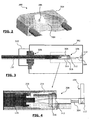
- the figure 3 is a partial representation of the collection system with respect to the vacuum chamber of a microscope.
- the figure 4 is a more detailed representation in section of a region of the figure 3 and the figure 5 is a representation in an isometric view of the same region.
- the collection optic 112 is intended to be arranged in a vacuum chamber 302 of the microscope and the adaptation means 114 as well as the optical fiber 116 and the analysis means 118 are arranged in an environment at the atmospheric pressure.
- the adaptation means 114, the optical fiber and the analysis means are deported out of the vacuum chamber 302 of the microscope.
- the collection optics 112 which is a parabolic mirror as shown in FIG. figure 2 , is integrally connected by means of two screws 304, to a first cylinder 306, said outer cylinder, at its proximal end 308.
- the collection optics 112 is connected to the outer cylinder so that the optical axis of the collection optics 112 merges with the axis of symmetry of the outer cylinder 306.
- This outer cylinder 306 enters the vacuum chamber through an opening 308 formed in a wall of the vacuum chamber. This opening 308 is arranged opposite the light radiation reflected by the collection optics 112.
- the outer cylinder 306 and the wall of the vacuum chamber 302 are held together by a sealed device 310 preserving the pressure level prevailing in the vacuum chamber.
- the outer cylinder 306 has at its proximal end 308, that is to say the end on which is fixed integrally the collection optics 112, a transparent sealing window 312 preserving the pressure level prevailing in the vacuum chamber 302 while allowing the light radiation collected and returned by the collection optics 112. to pass through.
- a transparent sealing window 312 preserving the pressure level prevailing in the vacuum chamber 302 while allowing the light radiation collected and returned by the collection optics 112. to pass through.
- the inside of the outer cylinder 306 is sealed separately from the vacuum chamber and there is an atmospheric pressure.
- a second cylinder 314, said inner cylinder, is disposed inside the outer cylinder 306 downstream of the sealing window 312, that is to say in the part or reigns an atmospheric pressure.
- the inner cylinder 314 has its axis of symmetry coincident with the axis of symmetry of the outer cylinder 306 and is therefore perfectly aligned with the optical axis of the collection optics 112.
- the inner cylinder 314 is disposed in the outer cylinder 306 of demountable way and free in rotation.
- the adaptation means 114 are arranged in this inner cylinder 314.
- the adaptation means 114 comprise a convergent collecting lens 316 arranged at the proximal end of the inner cylinder 314. This lens 316 makes it possible to adapt the width of the light radiation 108 to the input of the optical fiber 116.
- the input of the optical fiber is also disposed inside the inner cylinder downstream of the collecting lens 316 and centered very precisely with respect to the optical axis of the collecting lens 316.
- the inner cylinder may also comprise any optical element necessary for studying the sample, for example a polarizer.
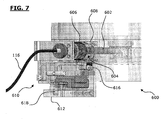
- the figure 6 is a partial view from above of a microscope implementing a cathodoluminescence detection system according to the second aspect of the invention.
- the collection optics is completely retracted, allowing a standard use of the microscope. It does not correspond to a view of the cathodoluminescence detection system in operation.
- the figure 7 is a representation of the microscope of the figure 6 according to a side view.
- the collection optics 112 is integrally connected to a cylinder 602 by two screws 304 at the proximal end 604 of the cylinder 602.
- the collection optics 112 is located in the vacuum chamber 302 of the microscope 600.
- cylinder 602 may also comprise the optical adaptation means 114 and the input of the optical fiber 116 which may for example be arranged in a second cylinder inserted in the cylinder 602 in a manner that is removable, free to rotate and mounted so that the The axis of symmetry merges with the axis of symmetry of the cylinder 602.
- the cylinder 602 may be the outer cylinder 306 and include the inner cylinder 314 as described above.
- the cylinder 602 enters the vacuum chamber 302 through an opening 604 formed in a wall of the vacuum chamber.
- This opening 604 is disposed opposite the light radiation returned by the collection optics 112. The diameter of this opening is greater than the outside diameter of the cylinder 602 so as to allow the cylinder to move. outside according to the three dimensions of space.
- This opening 604 may be the opening 308 described above.
- a bellows 606 is attached to the cylinder 602 and surrounds the cylinder 602 in a sealed manner.
- This bellows is also sealingly attached to the wall of the vacuum chamber 302, around the opening 602, thanks to a connecting piece 608 conforming to the external shape of the wall of the vacuum chamber around the opening 602.
- the connection of the bellows 606 with the cylinder 602 is tight as the connection of the bellows 606 with the wall of the vacuum chamber 302.
- the bellows 606 allows the displacement of the cylinder 606 in the three directions of space while by preserving at all times the sealing at each of its connections with the cylinder 602 on the one hand and the wall of the vacuum chamber 302 on the other hand.
- the cylinder 602 comprises a sealing window (not shown on the Figures 6-7 ).
- This sealing window makes it possible to preserve the tightness of the vacuum chamber 302.
- This sealing window may be disposed upstream or downstream of the optical adaptation means 114 and the input of the optical fiber 116.
- sealing window may for example be the sealing window 312 of figures 3-5 when both aspects of the cathodoluminescence system described in this application are combined.
- the cylinder 602 is integrally mounted on a three-dimensional displacement device 610 on the side of its distal end 612, that is to say its end on the opposite side to the collection optics 112.
- This three-dimensional displacement device 610 is placed on a plate 612 fixed integrally to the wall of the vacuum chamber.
- the device 610 comprises three micrometric screws 614, 616 and 618 making it possible to move the cylinder 602 along the three dimensions of the space.
- the collection optics 112 being integral with the cylinder 602, the displacement of the cylinder 602 causes the displacement of the collection optics 112.
- the operator can move collection optics from the outside of the microscope to better position it relative to the electron emission source and with respect to the sample to improve the conservation of the intensity of the light radiation collected in downstream of the collection optics as well as the spectral resolution of the light signal.
- the first and second aspects of the cathodoluminescence detection system can be combined.
- the cylinder 602 shown on the figure 6 and 7 can be replaced by the outer cylinder 306 of Figures 3 to 5 comprising the sealing window 312, the inner cylinder 314 in which the matching means 114 (in particular the collecting lens 316) and the entrance of the optical fiber 116 are arranged.
- the matching means 114 in particular the collecting lens 316
- the entrance of the optical fiber 116 are arranged.
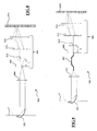
- the figure 8 is a schematic representation of a first example of the optical path of a cathodoluminescence system according to the third aspect of the invention.
- the optical path 800 of the figure 8 comprises as a means of collection a parabolic mirror 802 which may be identical to the parabolic mirror 200 of the figure 2 which collects light radiation from a sample illuminated by a particle beam.
- the optical path 800 comprises as a processing means a lens 804, which may be the lens 316 of the Figures 3 and 4 , receiving the light radiation connected by the parabolic mirror 802 and injecting it into a spectrometer 806 whose input is symbolized by the plane 808.
- the spectrometer 806 comprises a lens 810 arranged upstream of the network 812 of the spectrometer 806 and which returns the
- the spectrometer 806 further comprises a lens 814 disposed downstream of the array 812 of the spectrometer 806, which symbolizes the output of the spectrometer and which returns the light coming out of the spectrometer 806 to the spectrometer 806 on the spectrometer 806.
- a CCD camera 816 The spectrometer 806 and the camera 816 constitute the means of analysis of the cathodoluminescence system.
- the figure 9 is a schematic representation of a second example of the optical path of a cathodoluminescence system according to the third aspect of the invention.
- the optical path 900 of the figure 9 includes all the elements of the optical path 800 represented in figure 8 .
- the optical path 900 further comprises an optical fiber 902, which may be the optical fiber 116 of the Figures 3 and 4 .
- the input of the optical fiber 902 is positioned at the focal point of the lens 804 and the output of the optical fiber is positioned in the input plane of the spectrometer 806 materialized by the plane 808.
- the parameters of the optical elements in the optical path 900 remain identical to the parameters given with reference to the figure 1 .
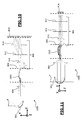
- FIGS. 10 and 11 are schematic representations according to different views of a third example of the optical path of a cathodoluminescence system according to the third aspect of the invention comprising a bundle of optical fibers.
- the optical path 1000 of Figures 10 and 11 includes all the elements of the optical path 800 represented in figure 8 .
- the optical path 1000 further comprises a bundle of optical fibers 1002, composed for example of several optical fibers such as the optical fiber 902 of the figure 9 .
- the input of the optical fiber bundle 1002 is positioned at the focal point of the lens 804 and the output of the optical fiber bundle is positioned in the input plane of the spectrometer 806 materialized by the plane 808.
- the parameters of the optical elements in the optical path 1000 remain identical to the parameters given with reference to the figure 1 .
- each of these three exemplary embodiments makes it possible to convey the light radiation emitted by the sample to the CCD camera while retaining more luminous intensity, an optimal spectral resolution and the possibility of using the invention in a charged particle microscope capable of forming probes of nanometric or even angstromic sizes.
- the optical fibers constituting the beam 1002 are arranged in a circular or hexagonal manner, around each other.
- the optical fibers composing the beam 1002 are aligned one on the other in a direction perpendicular to the dispersion direction of the spectrometer.
- the input 1202 and the output 1204 of the optical fiber bundle 1002 are schematically represented on the Figures 12 and 13 .
- FIGs 12 and 13 which are schematic representations of two configurations in which the light radiation arrives at the entrance of the optical fiber bundle at two different positions in the system of Figures 10 and 11 .
- the light radiation reaches the input 1202 of the optical fiber bundle 1002 at a point 1206 shifted to the left with respect to its center and in the configuration shown in FIG. figure 13 , the light radiation reaches the input 1202 of the beam 1002 of optical fibers at a point 1302 shifted to the right with respect to its center.
- the light radiation entering the beam 1002 of optical fibers does not leave the beam 1002 of optical fibers at the same positions.
- the three aspects of the present invention may be combined, two by two or all three on a single cathodoluminescence system.
Landscapes
- Chemical & Material Sciences (AREA)
- Analytical Chemistry (AREA)
- Investigating, Analyzing Materials By Fluorescence Or Luminescence (AREA)
- Microscoopes, Condenser (AREA)
- Analysing Materials By The Use Of Radiation (AREA)
Applications Claiming Priority (2)
| Application Number | Priority Date | Filing Date | Title |
|---|---|---|---|
| FR1054109A FR2960699B1 (fr) | 2010-05-27 | 2010-05-27 | Systeme de detection de cathodoluminescence souple et microscope mettant en oeuvre un tel systeme. |
| PCT/FR2011/050986 WO2011148072A1 (fr) | 2010-05-27 | 2011-04-29 | Systeme de detection de cathodoluminescence souple et microscope mettant en oeuvre un tel systeme |
Publications (2)
| Publication Number | Publication Date |
|---|---|
| EP2577706A1 EP2577706A1 (fr) | 2013-04-10 |
| EP2577706B1 true EP2577706B1 (fr) | 2014-07-23 |
Family
ID=43127317
Family Applications (1)
| Application Number | Title | Priority Date | Filing Date |
|---|---|---|---|
| EP11723542.4A Active EP2577706B1 (fr) | 2010-05-27 | 2011-04-29 | Systeme de detection de cathodoluminescence souple et microscope mettant en oeuvre un tel systeme |
Country Status (5)
| Country | Link |
|---|---|
| US (1) | US10157726B2 (enExample) |
| EP (1) | EP2577706B1 (enExample) |
| JP (3) | JP5833109B2 (enExample) |
| FR (1) | FR2960699B1 (enExample) |
| WO (1) | WO2011148072A1 (enExample) |
Families Citing this family (9)
| Publication number | Priority date | Publication date | Assignee | Title |
|---|---|---|---|---|
| JP7141874B2 (ja) * | 2017-09-29 | 2022-09-26 | 株式会社堀場製作所 | ルミネッセンス採光装置 |
| CN107703060B (zh) * | 2017-10-09 | 2020-12-15 | 苏州市光生环境科技有限公司 | 一种用于大气红外检测装置的调节支架 |
| CN108007488B (zh) * | 2017-11-29 | 2020-04-28 | 赫立科技(成都)有限公司 | 一种用于真空腔室内的位置调节装置 |
| JP7194202B2 (ja) * | 2018-05-30 | 2022-12-21 | ガタン インコーポレイテッド | 波長分解され角度分解されたカソードルミネッセンスのための装置および方法 |
| US11688581B2 (en) * | 2020-04-07 | 2023-06-27 | Gatan, Inc. | Apparatus for transmission electron microscopy cathodoluminescence |
| EP4165675A1 (en) * | 2020-06-10 | 2023-04-19 | ASML Netherlands B.V. | Replaceable module for a charged particle apparatus |
| EP3971938A1 (en) * | 2020-09-22 | 2022-03-23 | ASML Netherlands B.V. | Replaceable module for a charged particle apparatus |
| BR102020015402A2 (pt) * | 2020-07-28 | 2022-02-08 | Universidade Estadual De Campinas - Unicamp | Sistema de detecção de luz para microscópios de varredura de sonda |
| US11211223B1 (en) * | 2020-08-25 | 2021-12-28 | Fei Company | System and method for simultaneous phase contrast imaging and electron energy-loss spectroscopy |
Family Cites Families (27)
| Publication number | Priority date | Publication date | Assignee | Title |
|---|---|---|---|---|
| JPS614348U (ja) * | 1984-06-15 | 1986-01-11 | 株式会社日立製作所 | カソ−ドルミネツセンス装置 |
| DE3729846A1 (de) * | 1987-09-05 | 1989-03-23 | Zeiss Carl Fa | Kathodolumineszenzdetektor |
| US5013915A (en) * | 1988-05-20 | 1991-05-07 | Hitachi, Ltd. | Transmission type electron microscope |
| GB8920344D0 (en) * | 1989-09-08 | 1989-10-25 | Isis Innovation | Method and apparatus for imaging dislocations in materials |
| US5517033A (en) * | 1994-07-25 | 1996-05-14 | Gatan, Inc. | Apparatus for improved image resolution in electron microscopy |
| US5536941A (en) * | 1995-02-22 | 1996-07-16 | Gatan, Inc. | Rotatable wide angle camera and prism assembly for electron microscopes |
| US5724131A (en) * | 1995-06-14 | 1998-03-03 | The National University Of Singapore | Integrated emission microscope for panchromatic imaging, continuous wavelength spectroscopy and selective area spectroscopic mapping |
| JPH0945271A (ja) * | 1995-08-03 | 1997-02-14 | Hitachi Ltd | 撮像装置付き電子顕微鏡 |
| JP3718300B2 (ja) * | 1996-09-17 | 2005-11-24 | 株式会社トプコン | 試料分析装置 |
| US6061085A (en) * | 1997-02-07 | 2000-05-09 | Soft Imaging System Gmbh | Camera system for a transmission electron microscope |
| JP4392990B2 (ja) * | 1998-05-09 | 2010-01-06 | レニショウ パブリック リミテッド カンパニー | 電子顕微鏡および分光システム |
| GB0118981D0 (en) * | 2001-08-03 | 2001-09-26 | Renishaw Plc | Electron microscope and spectroscopy system |
| US6885445B2 (en) * | 1998-05-09 | 2005-04-26 | Renishaw Plc | Electron microscope and spectroscopy system |
| EP1145066B1 (de) * | 1998-12-21 | 2005-03-02 | Evotec OAI AG | Positionierung des messvolumens in einem scanning-mikroskopischen verfahren |
| JP3429282B2 (ja) * | 2001-02-02 | 2003-07-22 | リサーチ・インターナショナル・インコーポレーテッド | 自動化されたシステム、及びサンプルの分析方法 |
| JP4198325B2 (ja) * | 2001-03-06 | 2008-12-17 | 株式会社フォトロン | 多画面分光撮影装置 |
| GB0106342D0 (en) * | 2001-03-15 | 2001-05-02 | Renishaw Plc | Spectroscopy apparatus and method |
| GB0123053D0 (en) * | 2001-09-25 | 2001-11-14 | Oxford Instr Analytical Ltd | Electron detection device |
| JP3718818B2 (ja) * | 2001-10-31 | 2005-11-24 | 株式会社ユニソク | カソードルミネッセンス用試料ホルダ、及びカソードルミネッセンス分光分析装置 |
| JP2003157789A (ja) * | 2001-11-20 | 2003-05-30 | Hitachi High-Technologies Corp | 走査電子顕微鏡等のカソードルミネッセンス検出装置 |
| JP3888980B2 (ja) * | 2003-03-18 | 2007-03-07 | 株式会社日立ハイテクノロジーズ | 物質同定システム |
| JP4025836B2 (ja) * | 2004-10-07 | 2007-12-26 | コニカミノルタオプト株式会社 | 撮像装置及び携帯通信機器 |
| EP1739715A3 (en) * | 2005-06-29 | 2008-12-10 | Horiba, Ltd. | Sample measuring device |
| EP1956633A3 (en) * | 2007-02-06 | 2009-12-16 | FEI Company | Particle-optical apparatus for simultaneous observing a sample with particles and photons |
| EP1956632A1 (en) * | 2007-02-14 | 2008-08-13 | FEI Company | Particle-optical apparatus for simultaneous observing a sample with particles and photons |
| JP4988444B2 (ja) * | 2007-06-19 | 2012-08-01 | 株式会社日立製作所 | 検査方法および装置 |
| US7964846B2 (en) * | 2008-08-01 | 2011-06-21 | Gatan, Inc. | Retractable lens-coupled electron microscope camera with image sensor in electron microscope vacuum chamber |
-
2010
- 2010-05-27 FR FR1054109A patent/FR2960699B1/fr active Active
-
2011
- 2011-04-29 US US13/699,975 patent/US10157726B2/en active Active
- 2011-04-29 JP JP2013511720A patent/JP5833109B2/ja active Active
- 2011-04-29 WO PCT/FR2011/050986 patent/WO2011148072A1/fr not_active Ceased
- 2011-04-29 EP EP11723542.4A patent/EP2577706B1/fr active Active
-
2015
- 2015-01-29 JP JP2015015903A patent/JP5947928B2/ja active Active
- 2015-10-28 JP JP2015211726A patent/JP6208198B2/ja active Active
Also Published As
| Publication number | Publication date |
|---|---|
| JP2015122324A (ja) | 2015-07-02 |
| EP2577706A1 (fr) | 2013-04-10 |
| JP5833109B2 (ja) | 2015-12-16 |
| US10157726B2 (en) | 2018-12-18 |
| JP2013534692A (ja) | 2013-09-05 |
| FR2960699A1 (fr) | 2011-12-02 |
| FR2960699B1 (fr) | 2013-05-10 |
| JP2016054152A (ja) | 2016-04-14 |
| JP5947928B2 (ja) | 2016-07-06 |
| US20130087706A1 (en) | 2013-04-11 |
| JP6208198B2 (ja) | 2017-10-04 |
| WO2011148072A1 (fr) | 2011-12-01 |
Similar Documents
| Publication | Publication Date | Title |
|---|---|---|
| EP2577707B1 (fr) | Systeme de detection de cathodoluminescence reglable et microscope mettant en oeuvre un tel systeme | |
| EP2577706B1 (fr) | Systeme de detection de cathodoluminescence souple et microscope mettant en oeuvre un tel systeme | |
| CA2650856C (fr) | Tete optique miniaturisee a haute resolution spatiale et haute sensibilite, notamment pour l'imagerie de fluorescence confocale fibree | |
| EP2734884B1 (fr) | Dispositif optique d'éclairage conoscopique a cone creux pour microscope optique et procédé de microscopie optique en conoscopie | |
| EP1301763A2 (fr) | Ellipsometre spectroscopique compact | |
| WO2014049266A1 (fr) | Installation de mesures spectroscopiques a partir d'un plasma induit par laser | |
| EP0502752B1 (fr) | Appareil de spectrométrie | |
| EP3559636B1 (fr) | Dispositif et procédé pour observer le rayonnement rétrodiffusé par un objet | |
| EP1208401A1 (fr) | Appareil d'imagerie spectrometrique | |
| WO2020128333A1 (fr) | Appareil et procédé de micro-spectrométrie à balayage de faisceau lumineux | |
| FR2902202A1 (fr) | Microscope confocal interferometrique | |
| EP3069113B1 (fr) | Spectrophotomètre hyperspectral large bande pour analyser un objet dans le domaine fluorescent | |
| EP4094069A1 (fr) | Système de capture de valeurs ponctuelles pour constituer une image avec des rayonnements terahertz | |
| BE1026154B1 (fr) | Système optique | |
| WO2021170960A1 (fr) | Dispositif optique permettant de mesurer rapidement l'emission angulaire d'une source de lumiere de surface finie | |
| EP3575774B1 (fr) | Procédé d'observation de particules, en particulier des particules submicroniques | |
| FR2841983A1 (fr) | Procede et dispositif permettant de mesurer un flux lumineux retrodiffuse par un milieu disperse, non perturbe par les reflexions aux interfaces | |
| EP1376101A1 (fr) | Dispositif de mesure de caractéristiques photométriques d'un matériau | |
| WO2016203163A1 (fr) | Système et procédé de collection pour spectroscopie optique | |
| WO2020074800A1 (fr) | Dispositif d'inspection optique en champ sombre | |
| FR2919720A1 (fr) | Dispositif de spectroscopie laser | |
| EP3425354A1 (fr) | Spectrophotomètre hyperspectral large bande | |
| FR2807517A1 (fr) | Cellule optique multipassages par spectroscopie d'absorption, appareil de mise en oeuvre et procede de realisation |
Legal Events
| Date | Code | Title | Description |
|---|---|---|---|
| PUAI | Public reference made under article 153(3) epc to a published international application that has entered the european phase |
Free format text: ORIGINAL CODE: 0009012 |
|
| 17P | Request for examination filed |
Effective date: 20121213 |
|
| AK | Designated contracting states |
Kind code of ref document: A1 Designated state(s): AL AT BE BG CH CY CZ DE DK EE ES FI FR GB GR HR HU IE IS IT LI LT LU LV MC MK MT NL NO PL PT RO RS SE SI SK SM TR |
|
| DAX | Request for extension of the european patent (deleted) | ||
| 17Q | First examination report despatched |
Effective date: 20130917 |
|
| REG | Reference to a national code |
Ref country code: DE Ref legal event code: R079 Ref document number: 602011008594 Country of ref document: DE Free format text: PREVIOUS MAIN CLASS: H01J0037020000 Ipc: H01J0037244000 |
|
| GRAP | Despatch of communication of intention to grant a patent |
Free format text: ORIGINAL CODE: EPIDOSNIGR1 |
|
| RIC1 | Information provided on ipc code assigned before grant |
Ipc: H01J 37/256 20060101ALI20140117BHEP Ipc: H01J 37/02 20060101ALI20140117BHEP Ipc: H01J 37/26 20060101ALI20140117BHEP Ipc: H01J 37/22 20060101ALI20140117BHEP Ipc: H01J 37/244 20060101AFI20140117BHEP |
|
| INTG | Intention to grant announced |
Effective date: 20140218 |
|
| RAP1 | Party data changed (applicant data changed or rights of an application transferred) |
Owner name: UNIVERSITE PARIS-SUD 11 (PARIS XI) Owner name: CENTRE NATIONAL DE LA RECHERCHE SCIENTIFIQUE |
|
| GRAS | Grant fee paid |
Free format text: ORIGINAL CODE: EPIDOSNIGR3 |
|
| GRAA | (expected) grant |
Free format text: ORIGINAL CODE: 0009210 |
|
| AK | Designated contracting states |
Kind code of ref document: B1 Designated state(s): AL AT BE BG CH CY CZ DE DK EE ES FI FR GB GR HR HU IE IS IT LI LT LU LV MC MK MT NL NO PL PT RO RS SE SI SK SM TR |
|
| REG | Reference to a national code |
Ref country code: GB Ref legal event code: FG4D Free format text: NOT ENGLISH |
|
| REG | Reference to a national code |
Ref country code: CH Ref legal event code: EP |
|
| REG | Reference to a national code |
Ref country code: IE Ref legal event code: FG4D Free format text: LANGUAGE OF EP DOCUMENT: FRENCH |
|
| REG | Reference to a national code |
Ref country code: AT Ref legal event code: REF Ref document number: 679284 Country of ref document: AT Kind code of ref document: T Effective date: 20140815 Ref country code: CH Ref legal event code: NV Representative=s name: ABREMA AGENCE BREVET ET MARQUES, GANGUILLET, CH |
|
| REG | Reference to a national code |
Ref country code: DE Ref legal event code: R096 Ref document number: 602011008594 Country of ref document: DE Effective date: 20140904 |
|
| REG | Reference to a national code |
Ref country code: AT Ref legal event code: MK05 Ref document number: 679284 Country of ref document: AT Kind code of ref document: T Effective date: 20140723 |
|
| REG | Reference to a national code |
Ref country code: NL Ref legal event code: VDEP Effective date: 20140723 |
|
| REG | Reference to a national code |
Ref country code: LT Ref legal event code: MG4D |
|
| PG25 | Lapsed in a contracting state [announced via postgrant information from national office to epo] |
Ref country code: FI Free format text: LAPSE BECAUSE OF FAILURE TO SUBMIT A TRANSLATION OF THE DESCRIPTION OR TO PAY THE FEE WITHIN THE PRESCRIBED TIME-LIMIT Effective date: 20140723 Ref country code: SE Free format text: LAPSE BECAUSE OF FAILURE TO SUBMIT A TRANSLATION OF THE DESCRIPTION OR TO PAY THE FEE WITHIN THE PRESCRIBED TIME-LIMIT Effective date: 20140723 Ref country code: GR Free format text: LAPSE BECAUSE OF FAILURE TO SUBMIT A TRANSLATION OF THE DESCRIPTION OR TO PAY THE FEE WITHIN THE PRESCRIBED TIME-LIMIT Effective date: 20141024 Ref country code: BG Free format text: LAPSE BECAUSE OF FAILURE TO SUBMIT A TRANSLATION OF THE DESCRIPTION OR TO PAY THE FEE WITHIN THE PRESCRIBED TIME-LIMIT Effective date: 20141023 Ref country code: LT Free format text: LAPSE BECAUSE OF FAILURE TO SUBMIT A TRANSLATION OF THE DESCRIPTION OR TO PAY THE FEE WITHIN THE PRESCRIBED TIME-LIMIT Effective date: 20140723 Ref country code: NO Free format text: LAPSE BECAUSE OF FAILURE TO SUBMIT A TRANSLATION OF THE DESCRIPTION OR TO PAY THE FEE WITHIN THE PRESCRIBED TIME-LIMIT Effective date: 20141023 Ref country code: PT Free format text: LAPSE BECAUSE OF FAILURE TO SUBMIT A TRANSLATION OF THE DESCRIPTION OR TO PAY THE FEE WITHIN THE PRESCRIBED TIME-LIMIT Effective date: 20141124 Ref country code: ES Free format text: LAPSE BECAUSE OF FAILURE TO SUBMIT A TRANSLATION OF THE DESCRIPTION OR TO PAY THE FEE WITHIN THE PRESCRIBED TIME-LIMIT Effective date: 20140723 |
|
| PG25 | Lapsed in a contracting state [announced via postgrant information from national office to epo] |
Ref country code: HR Free format text: LAPSE BECAUSE OF FAILURE TO SUBMIT A TRANSLATION OF THE DESCRIPTION OR TO PAY THE FEE WITHIN THE PRESCRIBED TIME-LIMIT Effective date: 20140723 Ref country code: AT Free format text: LAPSE BECAUSE OF FAILURE TO SUBMIT A TRANSLATION OF THE DESCRIPTION OR TO PAY THE FEE WITHIN THE PRESCRIBED TIME-LIMIT Effective date: 20140723 Ref country code: PL Free format text: LAPSE BECAUSE OF FAILURE TO SUBMIT A TRANSLATION OF THE DESCRIPTION OR TO PAY THE FEE WITHIN THE PRESCRIBED TIME-LIMIT Effective date: 20140723 Ref country code: RS Free format text: LAPSE BECAUSE OF FAILURE TO SUBMIT A TRANSLATION OF THE DESCRIPTION OR TO PAY THE FEE WITHIN THE PRESCRIBED TIME-LIMIT Effective date: 20140723 Ref country code: LV Free format text: LAPSE BECAUSE OF FAILURE TO SUBMIT A TRANSLATION OF THE DESCRIPTION OR TO PAY THE FEE WITHIN THE PRESCRIBED TIME-LIMIT Effective date: 20140723 Ref country code: NL Free format text: LAPSE BECAUSE OF FAILURE TO SUBMIT A TRANSLATION OF THE DESCRIPTION OR TO PAY THE FEE WITHIN THE PRESCRIBED TIME-LIMIT Effective date: 20140723 Ref country code: CY Free format text: LAPSE BECAUSE OF FAILURE TO SUBMIT A TRANSLATION OF THE DESCRIPTION OR TO PAY THE FEE WITHIN THE PRESCRIBED TIME-LIMIT Effective date: 20140723 Ref country code: IS Free format text: LAPSE BECAUSE OF FAILURE TO SUBMIT A TRANSLATION OF THE DESCRIPTION OR TO PAY THE FEE WITHIN THE PRESCRIBED TIME-LIMIT Effective date: 20141123 |
|
| REG | Reference to a national code |
Ref country code: DE Ref legal event code: R097 Ref document number: 602011008594 Country of ref document: DE |
|
| PG25 | Lapsed in a contracting state [announced via postgrant information from national office to epo] |
Ref country code: EE Free format text: LAPSE BECAUSE OF FAILURE TO SUBMIT A TRANSLATION OF THE DESCRIPTION OR TO PAY THE FEE WITHIN THE PRESCRIBED TIME-LIMIT Effective date: 20140723 Ref country code: DK Free format text: LAPSE BECAUSE OF FAILURE TO SUBMIT A TRANSLATION OF THE DESCRIPTION OR TO PAY THE FEE WITHIN THE PRESCRIBED TIME-LIMIT Effective date: 20140723 Ref country code: SK Free format text: LAPSE BECAUSE OF FAILURE TO SUBMIT A TRANSLATION OF THE DESCRIPTION OR TO PAY THE FEE WITHIN THE PRESCRIBED TIME-LIMIT Effective date: 20140723 Ref country code: CZ Free format text: LAPSE BECAUSE OF FAILURE TO SUBMIT A TRANSLATION OF THE DESCRIPTION OR TO PAY THE FEE WITHIN THE PRESCRIBED TIME-LIMIT Effective date: 20140723 Ref country code: RO Free format text: LAPSE BECAUSE OF FAILURE TO SUBMIT A TRANSLATION OF THE DESCRIPTION OR TO PAY THE FEE WITHIN THE PRESCRIBED TIME-LIMIT Effective date: 20140723 Ref country code: IT Free format text: LAPSE BECAUSE OF FAILURE TO SUBMIT A TRANSLATION OF THE DESCRIPTION OR TO PAY THE FEE WITHIN THE PRESCRIBED TIME-LIMIT Effective date: 20140723 |
|
| PLBE | No opposition filed within time limit |
Free format text: ORIGINAL CODE: 0009261 |
|
| STAA | Information on the status of an ep patent application or granted ep patent |
Free format text: STATUS: NO OPPOSITION FILED WITHIN TIME LIMIT |
|
| 26N | No opposition filed |
Effective date: 20150424 |
|
| PG25 | Lapsed in a contracting state [announced via postgrant information from national office to epo] |
Ref country code: MC Free format text: LAPSE BECAUSE OF FAILURE TO SUBMIT A TRANSLATION OF THE DESCRIPTION OR TO PAY THE FEE WITHIN THE PRESCRIBED TIME-LIMIT Effective date: 20140723 Ref country code: LU Free format text: LAPSE BECAUSE OF FAILURE TO SUBMIT A TRANSLATION OF THE DESCRIPTION OR TO PAY THE FEE WITHIN THE PRESCRIBED TIME-LIMIT Effective date: 20150429 Ref country code: SI Free format text: LAPSE BECAUSE OF FAILURE TO SUBMIT A TRANSLATION OF THE DESCRIPTION OR TO PAY THE FEE WITHIN THE PRESCRIBED TIME-LIMIT Effective date: 20140723 |
|
| REG | Reference to a national code |
Ref country code: IE Ref legal event code: MM4A |
|
| REG | Reference to a national code |
Ref country code: FR Ref legal event code: PLFP Year of fee payment: 6 |
|
| PG25 | Lapsed in a contracting state [announced via postgrant information from national office to epo] |
Ref country code: IE Free format text: LAPSE BECAUSE OF NON-PAYMENT OF DUE FEES Effective date: 20150429 |
|
| PG25 | Lapsed in a contracting state [announced via postgrant information from national office to epo] |
Ref country code: MT Free format text: LAPSE BECAUSE OF FAILURE TO SUBMIT A TRANSLATION OF THE DESCRIPTION OR TO PAY THE FEE WITHIN THE PRESCRIBED TIME-LIMIT Effective date: 20140723 |
|
| REG | Reference to a national code |
Ref country code: FR Ref legal event code: PLFP Year of fee payment: 7 |
|
| PG25 | Lapsed in a contracting state [announced via postgrant information from national office to epo] |
Ref country code: SM Free format text: LAPSE BECAUSE OF FAILURE TO SUBMIT A TRANSLATION OF THE DESCRIPTION OR TO PAY THE FEE WITHIN THE PRESCRIBED TIME-LIMIT Effective date: 20140723 Ref country code: HU Free format text: LAPSE BECAUSE OF FAILURE TO SUBMIT A TRANSLATION OF THE DESCRIPTION OR TO PAY THE FEE WITHIN THE PRESCRIBED TIME-LIMIT; INVALID AB INITIO Effective date: 20110429 |
|
| PG25 | Lapsed in a contracting state [announced via postgrant information from national office to epo] |
Ref country code: BE Free format text: LAPSE BECAUSE OF NON-PAYMENT OF DUE FEES Effective date: 20150430 |
|
| PG25 | Lapsed in a contracting state [announced via postgrant information from national office to epo] |
Ref country code: TR Free format text: LAPSE BECAUSE OF FAILURE TO SUBMIT A TRANSLATION OF THE DESCRIPTION OR TO PAY THE FEE WITHIN THE PRESCRIBED TIME-LIMIT Effective date: 20140723 |
|
| REG | Reference to a national code |
Ref country code: FR Ref legal event code: PLFP Year of fee payment: 8 |
|
| PG25 | Lapsed in a contracting state [announced via postgrant information from national office to epo] |
Ref country code: MK Free format text: LAPSE BECAUSE OF FAILURE TO SUBMIT A TRANSLATION OF THE DESCRIPTION OR TO PAY THE FEE WITHIN THE PRESCRIBED TIME-LIMIT Effective date: 20140723 |
|
| PG25 | Lapsed in a contracting state [announced via postgrant information from national office to epo] |
Ref country code: AL Free format text: LAPSE BECAUSE OF FAILURE TO SUBMIT A TRANSLATION OF THE DESCRIPTION OR TO PAY THE FEE WITHIN THE PRESCRIBED TIME-LIMIT Effective date: 20140723 |
|
| REG | Reference to a national code |
Ref country code: CH Ref legal event code: PFUS Owner name: CENTRE NATIONAL DE LA RECHERCHE SCIENTIFIQUE, FR Free format text: FORMER OWNER: CENTRE NATIONAL DE LA RECHERCHE SCIENTIFIQUE, FR |
|
| REG | Reference to a national code |
Ref country code: DE Ref legal event code: R081 Ref document number: 602011008594 Country of ref document: DE Owner name: UNIVERSITE PARIS-SACLAY, FR Free format text: FORMER OWNERS: CENTRE NATIONAL DE LA RECHERCHE SCIENTIFIQUE, 75016 PARIS, FR; UNIVERSITE PARIS-SUD 11 (PARIS XI), ORSAY, FR Ref country code: DE Ref legal event code: R081 Ref document number: 602011008594 Country of ref document: DE Owner name: CENTRE NATIONAL DE LA RECHERCHE SCIENTIFIQUE, FR Free format text: FORMER OWNERS: CENTRE NATIONAL DE LA RECHERCHE SCIENTIFIQUE, 75016 PARIS, FR; UNIVERSITE PARIS-SUD 11 (PARIS XI), ORSAY, FR |
|
| PGFP | Annual fee paid to national office [announced via postgrant information from national office to epo] |
Ref country code: DE Payment date: 20250528 Year of fee payment: 15 |
|
| PGFP | Annual fee paid to national office [announced via postgrant information from national office to epo] |
Ref country code: GB Payment date: 20250429 Year of fee payment: 15 |
|
| PGFP | Annual fee paid to national office [announced via postgrant information from national office to epo] |
Ref country code: FR Payment date: 20250429 Year of fee payment: 15 |
|
| PGFP | Annual fee paid to national office [announced via postgrant information from national office to epo] |
Ref country code: CH Payment date: 20250602 Year of fee payment: 15 |