EP2577331B1 - System zur erkennung von batterieverbindungsfehlern - Google Patents
System zur erkennung von batterieverbindungsfehlern Download PDFInfo
- Publication number
- EP2577331B1 EP2577331B1 EP11792022.3A EP11792022A EP2577331B1 EP 2577331 B1 EP2577331 B1 EP 2577331B1 EP 11792022 A EP11792022 A EP 11792022A EP 2577331 B1 EP2577331 B1 EP 2577331B1
- Authority
- EP
- European Patent Office
- Prior art keywords
- difference
- temperature
- electrical
- measured
- connector
- Prior art date
- Legal status (The legal status is an assumption and is not a legal conclusion. Google has not performed a legal analysis and makes no representation as to the accuracy of the status listed.)
- Active
Links
Images


Classifications
-
- H—ELECTRICITY
- H01—ELECTRIC ELEMENTS
- H01M—PROCESSES OR MEANS, e.g. BATTERIES, FOR THE DIRECT CONVERSION OF CHEMICAL ENERGY INTO ELECTRICAL ENERGY
- H01M10/00—Secondary cells; Manufacture thereof
- H01M10/42—Methods or arrangements for servicing or maintenance of secondary cells or secondary half-cells
- H01M10/48—Accumulators combined with arrangements for measuring, testing or indicating the condition of cells, e.g. the level or density of the electrolyte
- H01M10/486—Accumulators combined with arrangements for measuring, testing or indicating the condition of cells, e.g. the level or density of the electrolyte for measuring temperature
-
- G—PHYSICS
- G01—MEASURING; TESTING
- G01R—MEASURING ELECTRIC VARIABLES; MEASURING MAGNETIC VARIABLES
- G01R31/00—Arrangements for testing electric properties; Arrangements for locating electric faults; Arrangements for electrical testing characterised by what is being tested not provided for elsewhere
- G01R31/50—Testing of electric apparatus, lines, cables or components for short-circuits, continuity, leakage current or incorrect line connections
- G01R31/66—Testing of connections, e.g. of plugs or non-disconnectable joints
-
- Y—GENERAL TAGGING OF NEW TECHNOLOGICAL DEVELOPMENTS; GENERAL TAGGING OF CROSS-SECTIONAL TECHNOLOGIES SPANNING OVER SEVERAL SECTIONS OF THE IPC; TECHNICAL SUBJECTS COVERED BY FORMER USPC CROSS-REFERENCE ART COLLECTIONS [XRACs] AND DIGESTS
- Y02—TECHNOLOGIES OR APPLICATIONS FOR MITIGATION OR ADAPTATION AGAINST CLIMATE CHANGE
- Y02E—REDUCTION OF GREENHOUSE GAS [GHG] EMISSIONS, RELATED TO ENERGY GENERATION, TRANSMISSION OR DISTRIBUTION
- Y02E60/00—Enabling technologies; Technologies with a potential or indirect contribution to GHG emissions mitigation
- Y02E60/10—Energy storage using batteries
Definitions
- This invention relates to an an electrical power system and a method for detection a connection failure in an electrical power system.
- Battery packs are generally made from a number of individual cells that are connected in series to provide higher voltages and/or parallel to provide higher current.
- a number of inventions address the fundamental issue of how to connect such cells including bolting, soldering, friction and welding methods.
- connection methods may all, at some point, be prone to failure. This can be caused by corrosion, physical impact, vibration or components coming loose. If bolts securing the cells become lose resistance increases and so does connection temperature. This could cause a fire. This is particularly troublesome in hybrid vehicles using high capacity and high voltage electrical storage systems for electrical motors.
- Battery safety systems employ thermal sensors placed near the battery cells which are used to detect thermal runaway events where cells have experienced a catastrophic failure. This failure can occur during charging or discharging. It is hoped that electrically disconnecting the battery would halt further heating and prevent fire from occurring. Such sensors often operate based on a single temperature threshold, for example 80 degrees centigrade, as a point where battery operation is considered unsafe.
- Battery safety systems occasionally include thermal sensors located on the electronic components that are used to carry the battery power. These components are often rated to withstand up to 175 degrees centigrade. Therefore, the temperature threshold used to determine mis-operation of such devices is usually set in excess of 100 degrees centigrade.
- JPH0831464A discloses a storage battery control device comprising a terminal temperature detection part, such as a thermistor on the electrical connector and a case temperature detection part disposed on the cell body.
- the storage battery control device provides means for detecting degradation of at least one of the electrical connectors.
- a malfunction detection part determines a temperature difference of the terminal temperature and the case temperature.
- JPS6078364A discloses to detect and report defects of a battery terminal by detecting the difference between the temperature of a varistor and the environmental temperature measured around the varistor.
- a temperature rise detecting circuit detects the difference between a rise of the temperature measured by a first thermistor and that measured by a second thermistor. If there is a difference, a defect in the battery terminal connection is detected and an alarm signal is actuated.
- the system of the invention is composed of a current sensor capable of monitoring current flow into and out of the battery and multiple temperature sensors arranged to sense various positions of the battery pack including at a minimum one sensor on the cell body and one sensor near the cell connections. During normal operation the temperature of the cell connections would be similar to the temperature of the body of each cell.
- An embodiment of the invention would include at least two temperature sensors located near the cell connections.
- the temperature of several different cell connections can be monitored and compared against each other. Since the current flowing through the battery is expected to be equal through cells connected in series, any individual cell connection exhibiting higher than expected temperatures with respect to other connections would be suspected to be in a degraded connection.
- thermocouples Similar detection methods can be accomplished with a variety of temperature sensing technologies including resistance transducers, thermocouples, infrared and semiconductor junctions.
- thermal monitoring, current monitoring or power monitoring methods would still employ the fundamental aspect of seeking to qualify cell connection health based on the energy being lost at a degraded connection that has some amount of current flowing through it.
- FIG 1 one example of an individual electrochemical cell (100) is shown.
- the cell body (101) contains the electrochemical mix and collector plates.
- the electricity is then delivered via thin cell tabs (99 and 102) which must be electrically connected to a load.
- Figure 2 shows a side view of the cell body (101) with the cell tab (102) bent over a circuit board (202).
- the circuit board would normally contain conductive elements which are brought into contact with the cell tab via a bolt (201) such that the cell tab and the circuit board form a connection (203). It can be appreciated from viewing this simple drawing that other connection methods including solder, rivets, welding or friction could accomplish the same goal.
- the circuit board (202) could be replaced with any conductive element including a solid metal bus bar, wires or sheet metal.
- the quality of the electrical connection (203) is monitored through temperature sensor (204) in close proximity to the connection.
- Figure 3 shows examples of a corroded cell tab (300) and a partially torn cell tab (301).
- bolting the cell tab into a battery assembly would probably work.
- the battery would be able to deliver significant current and would probably pass all production testing.
- heat will be generated due to the degradation of the cell connection. This could eventually lead to a fire.
- By monitoring the cell tab temperature these flaws would be detected in production or if they occur later in a field application. Even a small rise in temperature is sufficient to detect that a connection is starting to degrade.
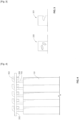
- Figure 4 shows a side view of multiple cell bodies (101) stacked together.
- Multiple cell tabs (102) form multiple connections (402) to the circuit board (202).
- multiple temperature sensors (204) are used to monitor each tab connection. If the temperature of one tab is significantly higher than the others, it will be detected as a degraded connection and possible safety hazard.
- Figure 5 shows a graph (500) with current flow on the horizontal X axis (502) and temperature on the vertical Y axis (501).
- line 503 may be considered a normal response for the cell connection rise in temperature as current increases.
- Line 504 may be considered a degraded connection that shows early signs of failure but is not yet a complete catastrophic failure.
- Line 505 is a catastrophic failure where continued increase in current will clearly cause the temperature to rise exponentially leading to a fire.
- These temperatures on the vertical Y axis (501) could be based on the temperature difference between different battery connections, or between one connection and ambient air, or between the cell connection and the cell body.
Landscapes
- Engineering & Computer Science (AREA)
- Manufacturing & Machinery (AREA)
- Chemical & Material Sciences (AREA)
- Chemical Kinetics & Catalysis (AREA)
- Electrochemistry (AREA)
- General Chemical & Material Sciences (AREA)
- Secondary Cells (AREA)
- Protection Of Static Devices (AREA)
Claims (7)
- Elektrisches Versorgungssystem, umfassend:a. zumindest eine Batteriezelle, umfassend:i. einen Zellkörper:ii. einen positiven elektrischen Verbinder zum Verbinden mit einem Leistungsübertragungselement;iii. einen negativen elektrischen Verbinder zum Verbinden mit dem Leistungsübertragungselement;iv. eine Last, die über das Leistungsübertragungselement Leistung aus dem Zellkörper bezieht; undb. ein Mittel zum Detektieren einer Verschlechterung von zumindest einem aus dem positiven und dem negativen elektrischen Verbinder,wobei das Mittel zum Detektieren einer Verschlechterung des zumindest einen aus dem positiven und dem negativen elektrischen Verbinder zumindest einen auf dem Zellkörper angeordneten Zellkörpertemperatursensor und zumindest einen Elektrischer-Verbinder-Temperatursensor umfasst, der nahe genug bei zumindest einem aus dem positiven und dem negativen Verbinder liegt, um die Temperatur des zumindest einen der Verbinder zu messen,und wobei das Mittel zum Detektieren einer Verschlechterung des zumindest einen aus den Verbindern ferner einen Verbinderstromsensor und einen softwarebetriebenen Komparator in elektrischer Kommunikation mit dem zumindest einen Zellkörpertemperatursensor, dem zumindest einen Elektrischer-Verbinder-Temperatursensor und dem Verbinderstromsensor umfasst, wobei der softwarebetriebene Komparator ein Mittel zum Berechnen der Differenz zwischen einer gemessenen Zellkörpertemperatur und einer zumindest einen gemessenen Elektrischer-Verbinder-Temperatur zu einem Zeitpunkt bei einem gemessenen Verbinderstrom zu dem Zeitpunkt umfasst.
- Elektrisches Versorgungssystem nach Anspruch 1, wobei das Mittel zum Detektieren einer Verschlechterung von zumindest einem aus dem positiven und dem negativen elektrischen Verbinder ferner einen Positiver-Verbinder-Temperatursensor, einen Negativer-Verbinder-Temperatursensor, einen softwarebetriebenen Komparator in elektrischer Kommunikation mit dem Positiver-Verbinder-Temperatursensor und dem Negativer-Verbinder-Temperatursensor umfasst, wobei der softwarebetriebene Komparator ein Mittel zum Berechnen der Differenz zwischen einer gemessenen Positiver-Verbinder-Temperatur und einer gemessenen Negativer-Verbinder-Temperatur umfasst, und wobei der softwarebetriebene Komparator ein Mittel zum Vergleichen der Differenz mit einer vorbestimmten Sicherheitsdifferenz umfasst; und wobei ferner der softwarebetriebene Komparator ein Alarmsignalmittel zum Betätigen eines Alarms, wenn die Differenz die vorbestimmte Sicherheitsdifferenz übersteigt, umfasst.
- Elektrisches Versorgungssystem nach Anspruch 1, wobei der zumindest eine Zellkörpertemperatursensor und der zumindest eine Elektrischer-Verbinder-Temperatursensor eines aus einem Widerstandswandler, einem Thermoelement, einem Wärmemonitor, einem Strommonitor und einem Leistungsmonitor umfasst.
- Elektrisches Versorgungssystem nach Anspruch 1, wobei der softwarebetriebene Komparator ferner Folgendes umfasst: ein Mittel zum Berechnen einer Temperaturdifferenz zwischen einer gemessenen Zellkörpertemperatur und einer gemessenen Elektrische-Verbindungs-Temperatur; ein Mittel zum Vergleichen der Differenz der gemessenen Temperatur mit einer vorbestimmten Temperatur-Sicherheitsdifferenz; und ein Mittel zum Ausgeben eines Alarms, wenn die Differenz die vorbestimmte Sicherheitsdifferenz übersteigt.
- Elektrisches Versorgungssystem nach Anspruch 4, ferner umfassend zumindest einen Stromsensor zum Messen von Strom in dem zumindest einen aus dem positiven und negativen elektrischen Verbinder, wobei der zumindest eine Stromsensor in elektrischer Kommunikation mit dem softwarebetriebenen Komparator steht, und wobei der softwarebetriebene Komparator ferner Folgendes umfasst: ein Mittel zum Berechnen der Temperaturdifferenz zwischen der gemessenen Zellkörpertemperatur und der gemessenen Elektrische-Verbindungs-Temperatur bei einem gemessenen Strom; ein Mittel zum Vergleichen der Differenz der gemessenen Temperatur mit einer vorbestimmten Temperatur-Sicherheitsdifferenz bei dem gemessenen Strom; und ein Mittel zum Ausgeben eines Alarms, wenn die Differenz die vorbestimmte Sicherheitsdifferenz übersteigt.
- Elektrisches Versorgungssystem nach Anspruch 4, umfassend einen Positiver-Verbinder-Temperatursensor, einen Negativer-Verbinder-Temperatursensor, einen softwarebetriebenen Komparator in elektrischer Verbindung mit dem Positiver-Verbinder-Temperatursensor und dem Negativer-Verbinder-Temperatursensor, wobei der softwarebetriebene Komparator ein Mittel zum Berechnen der Differenz zwischen einer gemessenen Positiver-Verbinder-Temperatur und einer gemessenen Negativ-Verbinder-Temperatur umfasst, und wobei der softwarebetriebene Komparator ein Mittel zum Vergleichen der Differenz mit einer vorbestimmten Sicherheitsdifferenz umfasst; und wobei ferner der softwarebetriebene Komparator ein Alarmsignalmittel zum Betätigen eines Alarms, wenn die Differenz eine vorbestimmte Sicherheitsdifferenz übersteigt, umfasst.
- Verfahren zum Detektieren eines Verbindungsfehlers in einem elektrischen Versorgungssystem, umfassend zumindest eine Batteriezelle, umfassend einen Zellkörper, einen positiven elektrischen Verbinder zum Verbinden mit einem Leistungsübertragungselement, einen negativen elektrischen Verbinder zum Verbinden mit dem Leistungsübertragungselement und eine Last, die über das Leistungsübertragungselement Leistung aus dem Zellkörper bezieht, wobei das Verfahren folgende Schritte umfasst:a. Platzieren von zumindest einem Zellkörpertemperatursensor auf dem Zellkörper;b. Platzieren von zumindest einem Elektrischer-Verbinder-Temperatursensor, der dazu ausgelegt ist, die Temperatur des zumindest einen aus dem positiven und dem negativen elektrischen Verbinder zu messen;c. Bereitstellen eines softwarebetriebenen Komparators und Versetzen des zumindest einen Zellkörpertemperatursensors und des zumindest einen Elektrischer-Verbinder-Temperatursensors in elektrische Kommunikation mit dem softwarebetriebenen Komparator;d. Messen einer Zellkörpertemperatur zu einem gegebenen Zeitpunkt;e. Messen einer Verbindungstemperatur zu einem gegebenen Zeitpunkt;f. Bestimmen der Differenz zwischen der Zellkörpertemperatur und der Verbindungstemperatur zu dem gegebenen Zeitpunkt;g. Vergleichen der Differenz mit einer vorbestimmten Sicherheitsdifferenz; undh. Bereitstellen eines Alarms, wenn die Differenz die vorbestimmte Sicherheitsdifferenz übersteigt, wobeii. nach Schritt (b) Platzieren eines Stromsensors auf zumindest einem aus den elektrischen Verbindern;i.1 nach Schritt (c) Versetzen auch des Stromsensors in elektrische Kommunikation mit dem softwarebetriebenen Komparator;j. nach Schritt (e) Messen eines Stroms zum gegebenen Zeitpunkt;k. nach Schritt (f) Bereitstellen einer zweiten vorbestimmten Sicherheitsdifferenz bei dem gemessenen Strom; undl. Vergleichen der Differenz beim gemessenen Strom mit der zweiten vorbestimmten Sicherheitsdifferenz; undm. Befolgen von Schritt (h).
Applications Claiming Priority (2)
| Application Number | Priority Date | Filing Date | Title |
|---|---|---|---|
| US12/795,533 US8427171B2 (en) | 2010-06-07 | 2010-06-07 | Battery connection failure detection system |
| PCT/IB2011/052061 WO2011154856A2 (en) | 2010-06-07 | 2011-05-11 | A battery connection failure detection system |
Publications (3)
| Publication Number | Publication Date |
|---|---|
| EP2577331A2 EP2577331A2 (de) | 2013-04-10 |
| EP2577331A4 EP2577331A4 (de) | 2015-02-11 |
| EP2577331B1 true EP2577331B1 (de) | 2024-09-18 |
Family
ID=45063965
Family Applications (1)
| Application Number | Title | Priority Date | Filing Date |
|---|---|---|---|
| EP11792022.3A Active EP2577331B1 (de) | 2010-06-07 | 2011-05-11 | System zur erkennung von batterieverbindungsfehlern |
Country Status (4)
| Country | Link |
|---|---|
| US (1) | US8427171B2 (de) |
| EP (1) | EP2577331B1 (de) |
| PL (1) | PL2577331T3 (de) |
| WO (1) | WO2011154856A2 (de) |
Families Citing this family (11)
| Publication number | Priority date | Publication date | Assignee | Title |
|---|---|---|---|---|
| US9052351B2 (en) * | 2012-09-19 | 2015-06-09 | Sensus Usa Inc. | Method and apparatus for preventing electricity meter failure |
| US9975434B2 (en) * | 2013-09-24 | 2018-05-22 | Ford Global Technologies, Llc | System and method for monitoring contactor health |
| CN104795606B (zh) * | 2014-01-21 | 2017-04-26 | 微宏动力系统(湖州)有限公司 | 液冷电池组系统 |
| WO2016009687A1 (ja) * | 2014-07-18 | 2016-01-21 | 株式会社東芝 | 組電池システム、および組電池の制御基板 |
| SE541183C2 (en) | 2016-05-13 | 2019-04-23 | Scania Cv Ab | Motor Vehicle and Method for Charging a Motor Vehicle Battery |
| CN106025405B (zh) * | 2016-07-22 | 2019-01-25 | 北京航空航天大学 | 一种动力电池失效快速监测报警装置及方法 |
| CN108964174A (zh) * | 2016-08-25 | 2018-12-07 | 杨更先 | 一种电力电池智能监控系统 |
| CN108132395B (zh) * | 2017-12-01 | 2020-03-17 | 浙江理工大学 | 一种电连接器加速退化试验方案优化方法 |
| CN114976495B (zh) * | 2021-02-19 | 2025-08-12 | 三星Sdi株式会社 | 连接器的热保护 |
| EP4047713A1 (de) * | 2021-02-19 | 2022-08-24 | Samsung SDI Co., Ltd. | Thermischer schutz für einen verbinder |
| CN116278761B (zh) * | 2023-03-28 | 2023-08-29 | 乐清市力诺机车部件有限公司 | 电瓶车的组合开关智能调控方法及系统 |
Family Cites Families (13)
| Publication number | Priority date | Publication date | Assignee | Title |
|---|---|---|---|---|
| JPS6078364A (ja) * | 1983-10-05 | 1985-05-04 | Nippon Soken Inc | バツテリ端子不良検出装置 |
| GB8528472D0 (en) * | 1985-11-19 | 1985-12-24 | British Aerospace | Battery state of charge indicator |
| JP3214782B2 (ja) * | 1994-07-15 | 2001-10-02 | トヨタ自動車株式会社 | 蓄電池管理装置 |
| US5767661A (en) * | 1997-03-21 | 1998-06-16 | Williams; Carlos | Battery charger |
| FR2820212A1 (fr) * | 2001-01-30 | 2002-08-02 | St Microelectronics Sa | Circuit de detection de mauvaise connexion d'alimentation |
| JP4162902B2 (ja) * | 2002-02-27 | 2008-10-08 | ナイルス株式会社 | コンパレータの異常検出装置 |
| JP4352688B2 (ja) * | 2002-11-27 | 2009-10-28 | トヨタ自動車株式会社 | 燃料電池の診断装置および診断方法 |
| US7862944B2 (en) * | 2005-07-13 | 2011-01-04 | Gm Global Technology Operations, Inc. | Method for detection and diagnosis of isolation faults in fuel cell hybrid vehicles |
| JP5170851B2 (ja) * | 2005-07-15 | 2013-03-27 | 古河電気工業株式会社 | 蓄電池充電状態検知方法および蓄電池充電状態検知装置 |
| JP5008863B2 (ja) * | 2005-11-30 | 2012-08-22 | プライムアースEvエナジー株式会社 | 二次電池用の制御装置、二次電池の温度推定方法を用いた二次電池の劣化判定方法 |
| KR20100007081A (ko) * | 2008-07-11 | 2010-01-22 | 삼성전자주식회사 | 표시 기판 및 이를 갖는 표시 패널 |
| JP2010032395A (ja) * | 2008-07-29 | 2010-02-12 | Tdk-Lambda Corp | 接触不良検出装置およびスイッチング電源 |
| JP5343512B2 (ja) * | 2008-10-30 | 2013-11-13 | トヨタ自動車株式会社 | 電池パック入出力制御装置 |
-
2010
- 2010-06-07 US US12/795,533 patent/US8427171B2/en active Active
-
2011
- 2011-05-11 EP EP11792022.3A patent/EP2577331B1/de active Active
- 2011-05-11 PL PL11792022.3T patent/PL2577331T3/pl unknown
- 2011-05-11 WO PCT/IB2011/052061 patent/WO2011154856A2/en not_active Ceased
Also Published As
| Publication number | Publication date |
|---|---|
| EP2577331A4 (de) | 2015-02-11 |
| WO2011154856A2 (en) | 2011-12-15 |
| PL2577331T3 (pl) | 2026-03-02 |
| WO2011154856A3 (en) | 2012-01-26 |
| US20110298472A1 (en) | 2011-12-08 |
| EP2577331A2 (de) | 2013-04-10 |
| US8427171B2 (en) | 2013-04-23 |
Similar Documents
| Publication | Publication Date | Title |
|---|---|---|
| EP2577331B1 (de) | System zur erkennung von batterieverbindungsfehlern | |
| EP3757590B1 (de) | Schaltung zur erkennung von thermischem durchgehen | |
| KR101487577B1 (ko) | 배터리 팩의 고장 진단 방법 및 장치, 이를 이용한 전력 릴레이 어셈블리 | |
| CN106025405A (zh) | 一种动力电池失效快速监测报警装置及方法 | |
| US9876261B2 (en) | Monitoring device for a battery, a lithium-ion battery, and method for the monitoring of a battery | |
| KR101293206B1 (ko) | 2차전지 카트리지 모듈의 부풀림 검출/보호 시스템 및 그방법, 이에 보호받는 2차전지 카트리지 모듈 | |
| WO2018135507A1 (ja) | 接触不良検出システム | |
| CN103262332B (zh) | 具有单元电压获取单元的蓄电池系统 | |
| JP2014022282A (ja) | 二次電池異常検出装置、二次電池、および二次電池異常検出方法 | |
| US20200212507A1 (en) | Electricity storage system and management device | |
| CA2706503C (en) | A battery connection failure detection system | |
| JP2018018815A (ja) | 検出システム | |
| KR102905953B1 (ko) | 배터리 모니터링 유닛 | |
| CN107402352A (zh) | 诊断方法、电池装置的运行方法、设备的运行方法和设备 | |
| US8965716B2 (en) | Method and apparatus for testing at least one temperature sensor in a vehicle | |
| WO2024044955A1 (zh) | 一种电池包及其检测方法、电池管理系统 | |
| TWI565172B (zh) | 電池監控系統與其方法 | |
| JP5348685B2 (ja) | リチウムイオン電池パック | |
| JP2019002795A (ja) | 異常検出装置および電池パック | |
| CN112313828A (zh) | 用于电能的存储单元、及其监控方法和车辆 | |
| US12442696B1 (en) | Battery monitoring system and method for monitoring a battery pack | |
| CN105628245A (zh) | 蓄电池表面温度在线检测装置、系统及方法 | |
| KR102956483B1 (ko) | 배선 온도 모니터링을 이용한 배터리 운용 제어장치 및 방법 | |
| KR20160058452A (ko) | 콤팩트한 회로 구조의 온도 감지 회로 | |
| CN104051804A (zh) | 用于在使用蓄电池模块时提高安全性的方法和装置 |
Legal Events
| Date | Code | Title | Description |
|---|---|---|---|
| PUAI | Public reference made under article 153(3) epc to a published international application that has entered the european phase |
Free format text: ORIGINAL CODE: 0009012 |
|
| 17P | Request for examination filed |
Effective date: 20121115 |
|
| AK | Designated contracting states |
Kind code of ref document: A2 Designated state(s): AL AT BE BG CH CY CZ DE DK EE ES FI FR GB GR HR HU IE IS IT LI LT LU LV MC MK MT NL NO PL PT RO RS SE SI SK SM TR |
|
| DAX | Request for extension of the european patent (deleted) | ||
| RAP1 | Party data changed (applicant data changed or rights of an application transferred) |
Owner name: PANACIS INC. |
|
| RIN1 | Information on inventor provided before grant (corrected) |
Inventor name: CARKNER, STEVE |
|
| RIC1 | Information provided on ipc code assigned before grant |
Ipc: G01R 31/04 20060101AFI20141222BHEP Ipc: H01M 10/48 20060101ALI20141222BHEP |
|
| A4 | Supplementary search report drawn up and despatched |
Effective date: 20150112 |
|
| STAA | Information on the status of an ep patent application or granted ep patent |
Free format text: STATUS: EXAMINATION IS IN PROGRESS |
|
| 17Q | First examination report despatched |
Effective date: 20180503 |
|
| RAP1 | Party data changed (applicant data changed or rights of an application transferred) |
Owner name: REVISION ELECTRONICS & POWER SYSTEMS INC. |
|
| RAP3 | Party data changed (applicant data changed or rights of an application transferred) |
Owner name: GALVION POWER SYSTEMS INC. |
|
| REG | Reference to a national code |
Ref country code: DE Ref legal event code: R079 Ref document number: 602011074989 Country of ref document: DE Free format text: PREVIOUS MAIN CLASS: G01R0031040000 Ipc: G01R0031660000 Ref country code: DE Ref legal event code: R079 Free format text: PREVIOUS MAIN CLASS: G01R0031040000 Ipc: G01R0031660000 |
|
| GRAP | Despatch of communication of intention to grant a patent |
Free format text: ORIGINAL CODE: EPIDOSNIGR1 |
|
| STAA | Information on the status of an ep patent application or granted ep patent |
Free format text: STATUS: GRANT OF PATENT IS INTENDED |
|
| RIC1 | Information provided on ipc code assigned before grant |
Ipc: H01M 10/48 20060101ALI20240313BHEP Ipc: G01R 31/66 20200101AFI20240313BHEP |
|
| INTG | Intention to grant announced |
Effective date: 20240409 |
|
| GRAS | Grant fee paid |
Free format text: ORIGINAL CODE: EPIDOSNIGR3 |
|
| GRAA | (expected) grant |
Free format text: ORIGINAL CODE: 0009210 |
|
| STAA | Information on the status of an ep patent application or granted ep patent |
Free format text: STATUS: THE PATENT HAS BEEN GRANTED |
|
| AK | Designated contracting states |
Kind code of ref document: B1 Designated state(s): AL AT BE BG CH CY CZ DE DK EE ES FI FR GB GR HR HU IE IS IT LI LT LU LV MC MK MT NL NO PL PT RO RS SE SI SK SM TR |
|
| REG | Reference to a national code |
Ref country code: GB Ref legal event code: FG4D |
|
| REG | Reference to a national code |
Ref country code: CH Ref legal event code: EP |
|
| REG | Reference to a national code |
Ref country code: DE Ref legal event code: R096 Ref document number: 602011074989 Country of ref document: DE |
|
| REG | Reference to a national code |
Ref country code: IE Ref legal event code: FG4D |
|
| REG | Reference to a national code |
Ref country code: SE Ref legal event code: TRGR |
|
| REG | Reference to a national code |
Ref country code: DE Ref legal event code: R081 Ref document number: 602011074989 Country of ref document: DE Owner name: STRYTEN ENERGY LLC, ALPHARETTA, US Free format text: FORMER OWNER: GALVION POWER SYSTEMS INC., OTTAWA, CA |
|
| REG | Reference to a national code |
Ref country code: LT Ref legal event code: MG9D |
|
| REG | Reference to a national code |
Ref country code: GB Ref legal event code: 732E Free format text: REGISTERED BETWEEN 20241219 AND 20241224 |
|
| PG25 | Lapsed in a contracting state [announced via postgrant information from national office to epo] |
Ref country code: GR Free format text: LAPSE BECAUSE OF FAILURE TO SUBMIT A TRANSLATION OF THE DESCRIPTION OR TO PAY THE FEE WITHIN THE PRESCRIBED TIME-LIMIT Effective date: 20241219 Ref country code: FI Free format text: LAPSE BECAUSE OF FAILURE TO SUBMIT A TRANSLATION OF THE DESCRIPTION OR TO PAY THE FEE WITHIN THE PRESCRIBED TIME-LIMIT Effective date: 20240918 |
|
| PG25 | Lapsed in a contracting state [announced via postgrant information from national office to epo] |
Ref country code: BG Free format text: LAPSE BECAUSE OF FAILURE TO SUBMIT A TRANSLATION OF THE DESCRIPTION OR TO PAY THE FEE WITHIN THE PRESCRIBED TIME-LIMIT Effective date: 20240918 |
|
| PG25 | Lapsed in a contracting state [announced via postgrant information from national office to epo] |
Ref country code: LV Free format text: LAPSE BECAUSE OF FAILURE TO SUBMIT A TRANSLATION OF THE DESCRIPTION OR TO PAY THE FEE WITHIN THE PRESCRIBED TIME-LIMIT Effective date: 20240918 |
|
| PG25 | Lapsed in a contracting state [announced via postgrant information from national office to epo] |
Ref country code: HR Free format text: LAPSE BECAUSE OF FAILURE TO SUBMIT A TRANSLATION OF THE DESCRIPTION OR TO PAY THE FEE WITHIN THE PRESCRIBED TIME-LIMIT Effective date: 20240918 |
|
| REG | Reference to a national code |
Ref country code: NL Ref legal event code: MP Effective date: 20240918 |
|
| PG25 | Lapsed in a contracting state [announced via postgrant information from national office to epo] |
Ref country code: RS Free format text: LAPSE BECAUSE OF FAILURE TO SUBMIT A TRANSLATION OF THE DESCRIPTION OR TO PAY THE FEE WITHIN THE PRESCRIBED TIME-LIMIT Effective date: 20241218 |
|
| REG | Reference to a national code |
Ref country code: GB Ref legal event code: 732E Free format text: REGISTERED BETWEEN 20250102 AND 20250108 |
|
| PG25 | Lapsed in a contracting state [announced via postgrant information from national office to epo] |
Ref country code: RS Free format text: LAPSE BECAUSE OF FAILURE TO SUBMIT A TRANSLATION OF THE DESCRIPTION OR TO PAY THE FEE WITHIN THE PRESCRIBED TIME-LIMIT Effective date: 20241218 Ref country code: LV Free format text: LAPSE BECAUSE OF FAILURE TO SUBMIT A TRANSLATION OF THE DESCRIPTION OR TO PAY THE FEE WITHIN THE PRESCRIBED TIME-LIMIT Effective date: 20240918 Ref country code: HR Free format text: LAPSE BECAUSE OF FAILURE TO SUBMIT A TRANSLATION OF THE DESCRIPTION OR TO PAY THE FEE WITHIN THE PRESCRIBED TIME-LIMIT Effective date: 20240918 Ref country code: GR Free format text: LAPSE BECAUSE OF FAILURE TO SUBMIT A TRANSLATION OF THE DESCRIPTION OR TO PAY THE FEE WITHIN THE PRESCRIBED TIME-LIMIT Effective date: 20241219 Ref country code: FI Free format text: LAPSE BECAUSE OF FAILURE TO SUBMIT A TRANSLATION OF THE DESCRIPTION OR TO PAY THE FEE WITHIN THE PRESCRIBED TIME-LIMIT Effective date: 20240918 Ref country code: BG Free format text: LAPSE BECAUSE OF FAILURE TO SUBMIT A TRANSLATION OF THE DESCRIPTION OR TO PAY THE FEE WITHIN THE PRESCRIBED TIME-LIMIT Effective date: 20240918 |
|
| REG | Reference to a national code |
Ref country code: AT Ref legal event code: MK05 Ref document number: 1725146 Country of ref document: AT Kind code of ref document: T Effective date: 20240918 |
|
| PG25 | Lapsed in a contracting state [announced via postgrant information from national office to epo] |
Ref country code: NL Free format text: LAPSE BECAUSE OF FAILURE TO SUBMIT A TRANSLATION OF THE DESCRIPTION OR TO PAY THE FEE WITHIN THE PRESCRIBED TIME-LIMIT Effective date: 20240918 |
|
| RAP2 | Party data changed (patent owner data changed or rights of a patent transferred) |
Owner name: STRYTEN ENERGY LLC |
|
| PG25 | Lapsed in a contracting state [announced via postgrant information from national office to epo] |
Ref country code: PT Free format text: LAPSE BECAUSE OF FAILURE TO SUBMIT A TRANSLATION OF THE DESCRIPTION OR TO PAY THE FEE WITHIN THE PRESCRIBED TIME-LIMIT Effective date: 20250120 Ref country code: IS Free format text: LAPSE BECAUSE OF FAILURE TO SUBMIT A TRANSLATION OF THE DESCRIPTION OR TO PAY THE FEE WITHIN THE PRESCRIBED TIME-LIMIT Effective date: 20250118 |
|
| PG25 | Lapsed in a contracting state [announced via postgrant information from national office to epo] |
Ref country code: RO Free format text: LAPSE BECAUSE OF FAILURE TO SUBMIT A TRANSLATION OF THE DESCRIPTION OR TO PAY THE FEE WITHIN THE PRESCRIBED TIME-LIMIT Effective date: 20240918 Ref country code: SM Free format text: LAPSE BECAUSE OF FAILURE TO SUBMIT A TRANSLATION OF THE DESCRIPTION OR TO PAY THE FEE WITHIN THE PRESCRIBED TIME-LIMIT Effective date: 20240918 |
|
| PG25 | Lapsed in a contracting state [announced via postgrant information from national office to epo] |
Ref country code: ES Free format text: LAPSE BECAUSE OF FAILURE TO SUBMIT A TRANSLATION OF THE DESCRIPTION OR TO PAY THE FEE WITHIN THE PRESCRIBED TIME-LIMIT Effective date: 20240918 |
|
| PG25 | Lapsed in a contracting state [announced via postgrant information from national office to epo] |
Ref country code: AT Free format text: LAPSE BECAUSE OF FAILURE TO SUBMIT A TRANSLATION OF THE DESCRIPTION OR TO PAY THE FEE WITHIN THE PRESCRIBED TIME-LIMIT Effective date: 20240918 Ref country code: EE Free format text: LAPSE BECAUSE OF FAILURE TO SUBMIT A TRANSLATION OF THE DESCRIPTION OR TO PAY THE FEE WITHIN THE PRESCRIBED TIME-LIMIT Effective date: 20240918 |
|
| PG25 | Lapsed in a contracting state [announced via postgrant information from national office to epo] |
Ref country code: CZ Free format text: LAPSE BECAUSE OF FAILURE TO SUBMIT A TRANSLATION OF THE DESCRIPTION OR TO PAY THE FEE WITHIN THE PRESCRIBED TIME-LIMIT Effective date: 20240918 |
|
| PG25 | Lapsed in a contracting state [announced via postgrant information from national office to epo] |
Ref country code: IT Free format text: LAPSE BECAUSE OF FAILURE TO SUBMIT A TRANSLATION OF THE DESCRIPTION OR TO PAY THE FEE WITHIN THE PRESCRIBED TIME-LIMIT Effective date: 20240918 Ref country code: SK Free format text: LAPSE BECAUSE OF FAILURE TO SUBMIT A TRANSLATION OF THE DESCRIPTION OR TO PAY THE FEE WITHIN THE PRESCRIBED TIME-LIMIT Effective date: 20240918 |
|
| REG | Reference to a national code |
Ref country code: DE Ref legal event code: R097 Ref document number: 602011074989 Country of ref document: DE |
|
| PGFP | Annual fee paid to national office [announced via postgrant information from national office to epo] |
Ref country code: DE Payment date: 20250319 Year of fee payment: 15 |
|
| PG25 | Lapsed in a contracting state [announced via postgrant information from national office to epo] |
Ref country code: DK Free format text: LAPSE BECAUSE OF FAILURE TO SUBMIT A TRANSLATION OF THE DESCRIPTION OR TO PAY THE FEE WITHIN THE PRESCRIBED TIME-LIMIT Effective date: 20240918 |
|
| PGFP | Annual fee paid to national office [announced via postgrant information from national office to epo] |
Ref country code: NO Payment date: 20250509 Year of fee payment: 15 |
|
| PLBE | No opposition filed within time limit |
Free format text: ORIGINAL CODE: 0009261 |
|
| STAA | Information on the status of an ep patent application or granted ep patent |
Free format text: STATUS: NO OPPOSITION FILED WITHIN TIME LIMIT |
|
| 26N | No opposition filed |
Effective date: 20250619 |
|
| REG | Reference to a national code |
Ref country code: CH Ref legal event code: H13 Free format text: ST27 STATUS EVENT CODE: U-0-0-H10-H13 (AS PROVIDED BY THE NATIONAL OFFICE) Effective date: 20251223 |
|
| PG25 | Lapsed in a contracting state [announced via postgrant information from national office to epo] |
Ref country code: LU Free format text: LAPSE BECAUSE OF NON-PAYMENT OF DUE FEES Effective date: 20250511 |
|
| PG25 | Lapsed in a contracting state [announced via postgrant information from national office to epo] |
Ref country code: CH Free format text: LAPSE BECAUSE OF NON-PAYMENT OF DUE FEES Effective date: 20250531 |
|
| REG | Reference to a national code |
Ref country code: BE Ref legal event code: MM Effective date: 20250531 |
|
| PG25 | Lapsed in a contracting state [announced via postgrant information from national office to epo] |
Ref country code: MC Free format text: LAPSE BECAUSE OF FAILURE TO SUBMIT A TRANSLATION OF THE DESCRIPTION OR TO PAY THE FEE WITHIN THE PRESCRIBED TIME-LIMIT Effective date: 20240918 |
|
| PGFP | Annual fee paid to national office [announced via postgrant information from national office to epo] |
Ref country code: SE Payment date: 20260312 Year of fee payment: 16 |
|
| PGFP | Annual fee paid to national office [announced via postgrant information from national office to epo] |
Ref country code: GB Payment date: 20260310 Year of fee payment: 16 |
|
| PG25 | Lapsed in a contracting state [announced via postgrant information from national office to epo] |
Ref country code: IE Free format text: LAPSE BECAUSE OF NON-PAYMENT OF DUE FEES Effective date: 20250511 |
|
| PG25 | Lapsed in a contracting state [announced via postgrant information from national office to epo] |
Ref country code: BE Free format text: LAPSE BECAUSE OF NON-PAYMENT OF DUE FEES Effective date: 20250531 |
|
| PGFP | Annual fee paid to national office [announced via postgrant information from national office to epo] |
Ref country code: FR Payment date: 20260309 Year of fee payment: 16 |