EP2576185B1 - Thermoformanlage aufweisendes transportsystem - Google Patents
Thermoformanlage aufweisendes transportsystem Download PDFInfo
- Publication number
- EP2576185B1 EP2576185B1 EP11743766.5A EP11743766A EP2576185B1 EP 2576185 B1 EP2576185 B1 EP 2576185B1 EP 11743766 A EP11743766 A EP 11743766A EP 2576185 B1 EP2576185 B1 EP 2576185B1
- Authority
- EP
- European Patent Office
- Prior art keywords
- chain
- rollers
- thermoforming
- plastic layer
- transport
- Prior art date
- Legal status (The legal status is an assumption and is not a legal conclusion. Google has not performed a legal analysis and makes no representation as to the accuracy of the status listed.)
- Active
Links
- 238000003856 thermoforming Methods 0.000 title claims description 37
- 230000005484 gravity Effects 0.000 claims description 10
- 239000002985 plastic film Substances 0.000 claims description 8
- 230000014759 maintenance of location Effects 0.000 claims 1
- 239000004033 plastic Substances 0.000 description 50
- 229920003023 plastic Polymers 0.000 description 50
- 230000032258 transport Effects 0.000 description 47
- 239000000463 material Substances 0.000 description 5
- 238000001816 cooling Methods 0.000 description 4
- 230000013011 mating Effects 0.000 description 4
- 238000005096 rolling process Methods 0.000 description 4
- 230000000295 complement effect Effects 0.000 description 3
- 238000010276 construction Methods 0.000 description 3
- 238000000034 method Methods 0.000 description 3
- 229920006255 plastic film Polymers 0.000 description 3
- 230000008859 change Effects 0.000 description 2
- 239000012809 cooling fluid Substances 0.000 description 2
- 239000012467 final product Substances 0.000 description 2
- 239000011888 foil Substances 0.000 description 2
- 238000010438 heat treatment Methods 0.000 description 2
- 238000010030 laminating Methods 0.000 description 2
- 238000000465 moulding Methods 0.000 description 2
- 230000008569 process Effects 0.000 description 2
- 239000000047 product Substances 0.000 description 2
- 238000004080 punching Methods 0.000 description 2
- 238000007514 turning Methods 0.000 description 2
- 238000005299 abrasion Methods 0.000 description 1
- 238000004220 aggregation Methods 0.000 description 1
- 230000002776 aggregation Effects 0.000 description 1
- 230000005540 biological transmission Effects 0.000 description 1
- 238000005260 corrosion Methods 0.000 description 1
- 230000007797 corrosion Effects 0.000 description 1
- 238000009795 derivation Methods 0.000 description 1
- 238000005516 engineering process Methods 0.000 description 1
- 230000002349 favourable effect Effects 0.000 description 1
- 239000012530 fluid Substances 0.000 description 1
- 239000000314 lubricant Substances 0.000 description 1
- 230000001050 lubricating effect Effects 0.000 description 1
- 238000005461 lubrication Methods 0.000 description 1
- 238000003754 machining Methods 0.000 description 1
- 238000004519 manufacturing process Methods 0.000 description 1
- 230000005855 radiation Effects 0.000 description 1
- 230000033764 rhythmic process Effects 0.000 description 1
- 238000007665 sagging Methods 0.000 description 1
- 239000002918 waste heat Substances 0.000 description 1
- 239000002699 waste material Substances 0.000 description 1
Images


Classifications
-
- B—PERFORMING OPERATIONS; TRANSPORTING
- B29—WORKING OF PLASTICS; WORKING OF SUBSTANCES IN A PLASTIC STATE IN GENERAL
- B29C—SHAPING OR JOINING OF PLASTICS; SHAPING OF MATERIAL IN A PLASTIC STATE, NOT OTHERWISE PROVIDED FOR; AFTER-TREATMENT OF THE SHAPED PRODUCTS, e.g. REPAIRING
- B29C51/00—Shaping by thermoforming, i.e. shaping sheets or sheet like preforms after heating, e.g. shaping sheets in matched moulds or by deep-drawing; Apparatus therefor
- B29C51/26—Component parts, details or accessories; Auxiliary operations
- B29C51/261—Handling means, e.g. transfer means, feeding means
-
- B—PERFORMING OPERATIONS; TRANSPORTING
- B65—CONVEYING; PACKING; STORING; HANDLING THIN OR FILAMENTARY MATERIAL
- B65G—TRANSPORT OR STORAGE DEVICES, e.g. CONVEYORS FOR LOADING OR TIPPING, SHOP CONVEYOR SYSTEMS OR PNEUMATIC TUBE CONVEYORS
- B65G17/00—Conveyors having an endless traction element, e.g. a chain, transmitting movement to a continuous or substantially-continuous load-carrying surface or to a series of individual load-carriers; Endless-chain conveyors in which the chains form the load-carrying surface
-
- B—PERFORMING OPERATIONS; TRANSPORTING
- B29—WORKING OF PLASTICS; WORKING OF SUBSTANCES IN A PLASTIC STATE IN GENERAL
- B29C—SHAPING OR JOINING OF PLASTICS; SHAPING OF MATERIAL IN A PLASTIC STATE, NOT OTHERWISE PROVIDED FOR; AFTER-TREATMENT OF THE SHAPED PRODUCTS, e.g. REPAIRING
- B29C51/00—Shaping by thermoforming, i.e. shaping sheets or sheet like preforms after heating, e.g. shaping sheets in matched moulds or by deep-drawing; Apparatus therefor
- B29C51/18—Thermoforming apparatus
-
- B—PERFORMING OPERATIONS; TRANSPORTING
- B29—WORKING OF PLASTICS; WORKING OF SUBSTANCES IN A PLASTIC STATE IN GENERAL
- B29C—SHAPING OR JOINING OF PLASTICS; SHAPING OF MATERIAL IN A PLASTIC STATE, NOT OTHERWISE PROVIDED FOR; AFTER-TREATMENT OF THE SHAPED PRODUCTS, e.g. REPAIRING
- B29C51/00—Shaping by thermoforming, i.e. shaping sheets or sheet like preforms after heating, e.g. shaping sheets in matched moulds or by deep-drawing; Apparatus therefor
- B29C51/18—Thermoforming apparatus
- B29C51/20—Thermoforming apparatus having movable moulds or mould parts
-
- B—PERFORMING OPERATIONS; TRANSPORTING
- B29—WORKING OF PLASTICS; WORKING OF SUBSTANCES IN A PLASTIC STATE IN GENERAL
- B29C—SHAPING OR JOINING OF PLASTICS; SHAPING OF MATERIAL IN A PLASTIC STATE, NOT OTHERWISE PROVIDED FOR; AFTER-TREATMENT OF THE SHAPED PRODUCTS, e.g. REPAIRING
- B29C51/00—Shaping by thermoforming, i.e. shaping sheets or sheet like preforms after heating, e.g. shaping sheets in matched moulds or by deep-drawing; Apparatus therefor
- B29C51/18—Thermoforming apparatus
- B29C51/20—Thermoforming apparatus having movable moulds or mould parts
- B29C51/24—Thermoforming apparatus having movable moulds or mould parts mounted on movable endless supports
-
- B—PERFORMING OPERATIONS; TRANSPORTING
- B29—WORKING OF PLASTICS; WORKING OF SUBSTANCES IN A PLASTIC STATE IN GENERAL
- B29C—SHAPING OR JOINING OF PLASTICS; SHAPING OF MATERIAL IN A PLASTIC STATE, NOT OTHERWISE PROVIDED FOR; AFTER-TREATMENT OF THE SHAPED PRODUCTS, e.g. REPAIRING
- B29C51/00—Shaping by thermoforming, i.e. shaping sheets or sheet like preforms after heating, e.g. shaping sheets in matched moulds or by deep-drawing; Apparatus therefor
- B29C51/26—Component parts, details or accessories; Auxiliary operations
- B29C51/261—Handling means, e.g. transfer means, feeding means
- B29C51/262—Clamping means for the sheets, e.g. clamping frames
-
- B—PERFORMING OPERATIONS; TRANSPORTING
- B29—WORKING OF PLASTICS; WORKING OF SUBSTANCES IN A PLASTIC STATE IN GENERAL
- B29C—SHAPING OR JOINING OF PLASTICS; SHAPING OF MATERIAL IN A PLASTIC STATE, NOT OTHERWISE PROVIDED FOR; AFTER-TREATMENT OF THE SHAPED PRODUCTS, e.g. REPAIRING
- B29C51/00—Shaping by thermoforming, i.e. shaping sheets or sheet like preforms after heating, e.g. shaping sheets in matched moulds or by deep-drawing; Apparatus therefor
- B29C51/26—Component parts, details or accessories; Auxiliary operations
- B29C51/42—Heating or cooling
- B29C51/421—Heating or cooling of preforms, specially adapted for thermoforming
- B29C51/422—Heating or cooling of preforms, specially adapted for thermoforming to produce a temperature differential
- B29C51/423—Heating or cooling of preforms, specially adapted for thermoforming to produce a temperature differential through the thickness of the preform
-
- B—PERFORMING OPERATIONS; TRANSPORTING
- B29—WORKING OF PLASTICS; WORKING OF SUBSTANCES IN A PLASTIC STATE IN GENERAL
- B29C—SHAPING OR JOINING OF PLASTICS; SHAPING OF MATERIAL IN A PLASTIC STATE, NOT OTHERWISE PROVIDED FOR; AFTER-TREATMENT OF THE SHAPED PRODUCTS, e.g. REPAIRING
- B29C55/00—Shaping by stretching, e.g. drawing through a die; Apparatus therefor
- B29C55/02—Shaping by stretching, e.g. drawing through a die; Apparatus therefor of plates or sheets
-
- B—PERFORMING OPERATIONS; TRANSPORTING
- B29—WORKING OF PLASTICS; WORKING OF SUBSTANCES IN A PLASTIC STATE IN GENERAL
- B29C—SHAPING OR JOINING OF PLASTICS; SHAPING OF MATERIAL IN A PLASTIC STATE, NOT OTHERWISE PROVIDED FOR; AFTER-TREATMENT OF THE SHAPED PRODUCTS, e.g. REPAIRING
- B29C55/00—Shaping by stretching, e.g. drawing through a die; Apparatus therefor
- B29C55/02—Shaping by stretching, e.g. drawing through a die; Apparatus therefor of plates or sheets
- B29C55/04—Shaping by stretching, e.g. drawing through a die; Apparatus therefor of plates or sheets uniaxial, e.g. oblique
-
- B—PERFORMING OPERATIONS; TRANSPORTING
- B29—WORKING OF PLASTICS; WORKING OF SUBSTANCES IN A PLASTIC STATE IN GENERAL
- B29C—SHAPING OR JOINING OF PLASTICS; SHAPING OF MATERIAL IN A PLASTIC STATE, NOT OTHERWISE PROVIDED FOR; AFTER-TREATMENT OF THE SHAPED PRODUCTS, e.g. REPAIRING
- B29C55/00—Shaping by stretching, e.g. drawing through a die; Apparatus therefor
- B29C55/02—Shaping by stretching, e.g. drawing through a die; Apparatus therefor of plates or sheets
- B29C55/04—Shaping by stretching, e.g. drawing through a die; Apparatus therefor of plates or sheets uniaxial, e.g. oblique
- B29C55/08—Shaping by stretching, e.g. drawing through a die; Apparatus therefor of plates or sheets uniaxial, e.g. oblique transverse to the direction of feed
-
- B—PERFORMING OPERATIONS; TRANSPORTING
- B65—CONVEYING; PACKING; STORING; HANDLING THIN OR FILAMENTARY MATERIAL
- B65G—TRANSPORT OR STORAGE DEVICES, e.g. CONVEYORS FOR LOADING OR TIPPING, SHOP CONVEYOR SYSTEMS OR PNEUMATIC TUBE CONVEYORS
- B65G21/00—Supporting or protective framework or housings for endless load-carriers or traction elements of belt or chain conveyors
- B65G21/20—Means incorporated in, or attached to, framework or housings for guiding load-carriers, traction elements or loads supported on moving surfaces
- B65G21/22—Rails or the like engaging sliding elements or rollers attached to load-carriers or traction elements
-
- Y—GENERAL TAGGING OF NEW TECHNOLOGICAL DEVELOPMENTS; GENERAL TAGGING OF CROSS-SECTIONAL TECHNOLOGIES SPANNING OVER SEVERAL SECTIONS OF THE IPC; TECHNICAL SUBJECTS COVERED BY FORMER USPC CROSS-REFERENCE ART COLLECTIONS [XRACs] AND DIGESTS
- Y10—TECHNICAL SUBJECTS COVERED BY FORMER USPC
- Y10T—TECHNICAL SUBJECTS COVERED BY FORMER US CLASSIFICATION
- Y10T428/00—Stock material or miscellaneous articles
- Y10T428/24—Structurally defined web or sheet [e.g., overall dimension, etc.]
- Y10T428/24628—Nonplanar uniform thickness material
Definitions
- the invention relates to a thermoforming plant.
- Thermoforming plants are widely known. Such a system consists of several stations.
- a transport system with a chain engages a plastic layer to be processed at the beginning of the system. Often this is an endless film or a continuous film tube, which are pulled from a roll.
- the transport system transports the plastic layer to be processed through the usually linearly serially arranged stations of the system. On the way the plastic layer is heated and gets in the heated state in the actual thermoforming station. There it is shaped, stamped as desired or otherwise separated and handed over to the output of the plant.
- the holder for the plastic layer usually a chain with needles or clips, usually try to keep the web stretched transversely under a slight bias, ie in a direction substantially perpendicular to the machine direction and within the plane of the plastic layer.
- the lateral forces exerted on the transport system affect the service life of the transport system.
- support rollers are provided for receiving the lateral force in addition to the actual chain.
- the support rollers do not have to be arranged on each chain link. Most of them are only occasionally found at regular intervals on an encircling transport chain.
- DE 23 35 246 discloses machines for processing plastic and similar films and the feeding of the films, for example, from one processing position to another.
- the feed is made by each a chain drive to each side of the film web, the chains take the film through mandrels at the two edges.
- the movement is usually intermittent, so that sufficient time remains in the processing stations, for example, for punching or molding.
- thermoforming apparatus having an upper and a lower clamping frame for clamping the material to be deformed and a material transporting the material to the clamping frame transporting the material detected at both extending in the transport direction edges, wherein at least the one clamping frame, which is associated with the transport device, in the direction is tapered to its clamping surface and that the transport device is adapted in position to the contour of the taper.
- DE 298 16 386 U1 discloses a sheet and plate transport apparatus in thermoforming machines comprising two opposed, perimeter, needle-studded conveyor chains, each held in a guide profile at each chain center with guides from above and below between the projecting over the rollers tabs of the conveyor chain engages, wherein the guide profile is held by a carrier to the thermoforming machine.
- DE 196 29 196 A1 discloses a device for thermoforming of films, in particular for laminating moldings with laminating films.
- the film is drawn with needles of transport chains of a transport device in a thermoforming device and clamped there between clamping frame and then formed with suitable molds or molded onto a shaped body.
- the transport device is partially between the longitudinal clamping strips of the clamping frame.
- DE 2 062 506 discloses a pinch chain transport device for plastic films in thermoforming machines or the like, in which link chains with circumferentially arranged on a plurality of tabs spring-clamping device along guides and wherein the spring-clamping devices the edges of the film webs or sections in control dependence of casserole curves at the beginning capture the transport path and release at the end, wherein the spring-clamping device each consists of a fixed jaw and a resiliently raised and lowered relative to this jaw.
- the invention is based on the object to provide an improved transport system and thus an improved thermoforming system available.
- thermoforming system for processing a plastic layer, with a chain for transporting the plastic layer through the thermoforming system, wherein the chain has a holding means for the plastic layer, so that the plastic layer in the operation of the thermoforming system on the holding means transverse to a chain direction a transverse force the chain can exert, and a guide for the chain for receiving the transverse force, the chain having a basic structure with a plurality of rollers between tabs for receiving a transport directing force, wherein the rollers are oriented upright so that the transverse force acts transversely to their roller axes, wherein the guide engages directly on the rollers, characterized in that the chain is supported vertically on gravity support rollers, wherein the gravity support rollers are formed separately from the rollers and have a horizontal axis.
- thermoforming plant is an exemplary plastics processing plant.
- the "plastic layer” may in particular consist of a film web, a tubular film web or individual plastic plates.
- the “chain” is normally constructed with a conventional basic structure, ie with articulated links. Between outer plates and inner plates there are bolts on which sleeves are stuck, which in turn carry rollers.
- the "holding means” are usually arranged in thermoforming machines needles or clips.
- the plastic layer is either needled or clamped in these.
- the plastic layer can exert "lateral forces" on the chain. This happens, for example, when the plastic film thermally narrows when two chain rails diverge for tightening the plastic layer or even by the gravity of the plastic layer.
- a lateral force is understood to mean a force which is exerted exactly horizontally at right angles to the machine direction.
- transverse force for example, the two chain rails on the right and left edges of the plastic layer are often arranged divergently to spread the plastic layer; the chain direction then deviates by a few degrees from a parallelism to the machine direction.
- the plastic layer sometimes behaves not exactly homogeneous, so inhomogeneous forces can occur.
- the lateral force in any case substantially, ie with a deviation of less than 20 ° or better less than 10 °, it is perpendicular to the machine direction and the chain direction and acts essentially horizontally, that is to say less than 20 ° or 10 ° Deviation from the horizontal.
- the "guide” is available on the system side or on the transport system side for the chain. It prevents excessive deflection of the chain in a lateral direction under the influence of the lateral force.
- the guide is given by a chain rail.
- rollers need to be upright. Rather, it is also conceivable that the chain is flattened in their way and later rearranged, if desired. The simplest is, however, that all roles are oriented upright, especially all practically vertical.
- the lateral force acts on the chain.
- the chain can remove this lateral force but rolling. In particular, it does not lead to tilting of the chain links against each other, but the force acting substantially perpendicular to the roller axis only leads to the fact that the chain links can pivot against each other about the intended pivot axis.
- thermoforming plant for processing a plastic layer
- a chain for transporting the plastic layer through the thermoforming system
- the chain has a holding means for the plastic layer, so that the plastic layer can exert on the chain in the region of the thermoforming system via the holding means transverse to a chain direction of a transverse force
- the guide for the chain for absorbing the lateral force
- the chain has a basic structure with a plurality of rollers between tabs for receiving a transport directing force
- the chain is free of transverse force support rollers.
- Prior art chains have had these lateral force support rollers which have supported themselves on a ledge remote from the rollers to absorb the transverse force.
- the drive of the chain intervened in the basic structure of the chain, so to the local roles.
- the transverse force support rollers were provided to receive the transverse forces from the plastic web.
- the embodiment proposed here combines propulsion and lateral force resistance both on the rollers of the basic structure.
- the transverse force support rollers can therefore be omitted.
- the chain could rest vertically on a sliding surface with its outer flaps or glides attached thereto. With such a construction, it is not necessary to provide further measures for receiving the weight of the chain or for vertically acting on the chain force components.
- the chain is supported vertically on gravity support rollers.
- a preferred embodiment of the chain provides that rollers relative to the guide have a vertically self-centering under transverse force contour, the guide provides a lateral complementary contour.
- rollers can have a contour horizontally self-centering under the force of gravity, the guide providing a lower complementary contour.
- roller which sits on the chain sleeve is not smooth cylindrical, but has a crown.
- polygonal cross sections of the role are easy to imagine, such as a sloping square or a hexagonal contour.
- the guide ie in particular a chain rail
- can independently of one another provide laterally or below, preferably laterally and below, a complementary form for the self-centering roller contour.
- a spherical outer contour of the chain rollers can thus be imagined that the chain rail profile provides a spherical concave shell around the rollers around within the tabs.
- the spherical surface of the individual roll oriented towards the plastic layer then runs into the concave shell of the laterally arranged chain rail so that the roll centers vertically, namely at the mean height of its own spherical structure and simultaneously on the middle one Height of the lateral bowl-shaped receptacle.
- thermoforming system for processing a plastic layer comprising a chain for transporting the plastic layer through the thermoforming system, wherein the chain has a holding means for the plastic layer, so that the plastic layer in the operation of the thermoforming system via the holding means transverse to a chain direction a transverse force on the chain and a guide for the chain for absorbing the lateral force, the chain runs around in a chain rail profile and has a basic structure with a plurality of rollers between tabs for receiving a transport directing force, wherein the chain rail profile has a mirror-symmetrical cross section with an upright oriented axis of symmetry ,
- the chain runs in a chain rail.
- the chain runs only in one direction in a profile and runs for the way back in a separate profile or free. This feature is realized when either one of the then several chain rail profiles mirror symmetry with upright symmetry axis, or if the then several chain rails on one side of the plastic layer together meet this feature.
- an "upright” oriented axis of symmetry should in particular be understood to mean a vertically oriented axis of symmetry, which preferably extends over the course of the chain rail profile, which is generally linear, everywhere, thus resulting in a plane of symmetry. There is no exact vertical alignment necessary. First, be on it pointed out that even an engineering deviation from the vertical in the result for the chain rail is still quasi vertical. In addition, the feature can be readily implemented with an angular deviation of, for example, a maximum of 10 or 20 ° relative to the vertical.
- a symmetrical chain rail profile in particular in the case of mirror symmetry with inclusion of the circulating chain, preferably has a cooling bore in the axis of symmetry. A cooling fluid pumped thereby can then cool the profile and the chain symmetrically. This increases the precision of the machining.
- cooling holes can be arranged in the axis of symmetry. It is also understood that cooling holes can be provided in addition to the axis of symmetry in the profile.
- thermoforming plant for processing a plastic layer, comprising a chain for transporting the plastic layer of the thermoforming plant, the chain having a holding means for the plastic layer, so that the plastic layer can exert a transverse force on the chain across the holding means across the holding means transverse to a chain direction, and with a guide for the chain for absorbing the lateral force
- the chain runs in a chain rail profile and has a basic structure with a plurality of rollers between tabs for receiving a transport directing force, wherein a heating body is provided for heating the plastic layer and wherein the chain rail profile at its side has a bevel towards the holding means.
- the "radiator” is usually a flat radiator. Such radiators can be located both above and below the transport path for the plastic sheet in thermoforming systems. In most cases, at least one radiator is arranged above the plastic layer. This radiates downwards so that the plastic layer transported by means of the transport chains is heated in front of the forming station and thus softened.
- the holding means for the plastic layer are arranged as close as possible to the actual basic structure of the chain. Very often, short curved needles are starting from the chain links. These protrude laterally from the chain longitudinal direction. There, the plastic layer is needled on the sides.
- the chain rail profile has a side, which is oriented to the held plastic layer, a bottom, an upper side and an opposite side in a horizontally arranged plastic layer.
- the side facing the plastic layer has the chamfer, so in the course of jumps back up, so away from a vertical above the holding means more and more.
- the side facing the plastic layer is completely bevelled.
- the bevel preferably continues into the top of the chain rail profile.
- the chain rail profile has a substantially triangular cross-sectional shape, wherein in a symmetrical structure at the top a tip of the triangle is arranged so that the top of this edge extends obliquely down to the holding means.
- thermoforming system Immediately advantageous is also a transport system with a chain for use in a thermoforming system as described above.
- thermoforming system and / or such a transport system extend directly to a thermoformed product produced therewith.
- a transport device 1 not claimed here FIG. 1 consists essentially of a chain rail profile 2, a strip 3 lying thereon and a chain 4, which runs back in a flow chamber 5 and in a return chamber 6 (where the chain 4 is not shown).
- the transport device 1 is located in a thermoforming plant. There, thermoforming products are formed from an endless film web with intermittent transport and singulated with a punching tool.
- thermoforming plant is at least one further transport device, which is exactly like the transport device 1 is executed, but mirror-inverted. Needles 7 of the chain 4 in the transport device 1 shown and opposite needles of the local transport device thus access each other so that in a transport space 8, the continuous film web can be transported by the chain 4 is driven or both chains are driven.
- the chain 4 is constructed in a conventional manner. Between outer plates 9 (identified by way of example) and inner plates 10 (identified by way of example), bolts 11 with sleeves (not shown) and in each case one roller 12 are arranged.
- the supply chamber 5 has on the transport space 8 towards side of the roller 12 a rail-shaped mating contour 13 matching the contour of the roller 12.
- the bolt 11 is not vertically centered in the tabs, but slightly offset upwards, so that a smooth end 14 results downwards.
- the strip 15 is spaced at regular intervals Locking lugs 17 are secured in a receiving space on an underside 18 of the chain rail profile 2.
- a securing groove 19 Toward the transport space 8 towards the side of the mating contour 13 at approximately the same height is a securing groove 19 in which tips of the needles 7 run.
- the rounded rounded at right angles bar 3 is on the entire chain rail profile 2.
- a bearing surface 21 on the chain rail profile 2 for the bar 3 is highly sloped, namely at an angle of about 45 ° to the horizontal. Also obliquely continues from the end of a side 22 of the chain rail profile 2, so that the securing groove 19 of the chain rail profile 2 is clearly the furthest to the transport space 8 part of the transport device 1, together with the needles. 7
- the chain 4 runs with a needle-punched endless film web through the pre-run space 5. At the end of the transport device there is a turning point. From there, the chain 4 runs back through the return chamber 6 to a second turning point and from out again into the flow chamber. 5
- the endless film web exerts a transverse force on the chain 4 via the needles 7.
- the chain rail profile is folded, by 90 °, and the chain then runs horizontally. This results in a more favorable flow of forces on the support and tension roller. This results in a purely rolling load.
- the chain is not braced.
- the chain 4 is vertically self-centering: due to the transverse force to the transport space, the roller 12 is drawn with its octagonal outer contour in the mating contour 13.
- the outer contour of the roller 12 is convex, the inner contour of the mating contour 13 on the rail, however, concave. In this way it is ensured that the roller 13 removes the load on the chain rail profile 2.
- the sliding surface 16 is provided on the bottom strip 15.
- the chain 4 thus slides in the vertical axis on the sliding elements as a result of their own weight on the sliding surface 16. This is observed in particular in the return in the return space 6, because there is no lateral force exerted on the chain, which could center the chain approximately vertically.
- the needled film of radiators in a radiator region 27 can be heated practically to its edge.
- a chain rail profile 31 and a chain roller 32 are self-centering in both horizontal and vertical directions so that both lateral force 33 and gravity 34 will result in self-centering, namely, the lateral force 33 in the vertical direction and the gravity 34 in the horizontal direction ,
- FIG. 3 Various other embodiments for self-centering rollers are shown in FIG. 3 shown.
- the invention relates to a thermoforming plant for processing a plastic layer, which for the processing curve at a precisely-adapted rhythm in the required collection of roll or plate form available film web to plastic processing machine, the safe washerertransportieriana by or along various processing processes to the finishing of the web and the Storing or stacking of the final product is improved.
- the object of the newly presented method with the newly presented device is to guide a plastic film web 41.
- a specially constructed, profiled, pressure, temperature and corrosion resistant guide rail pair 42 is used for this purpose. This works in parallel operation and is able to accommodate a roller chain pair 43.
- the roller chain pair is equipped with a number of attachment elements 47, for example in the form of hooks or needles.
- the Leit-rail pair 42 leads the roller chain pair 43 supported on three sides and rolling smoothly.
- the guide rail pair 42 is provided with holes 44 for the passage of cooling fluid.
- Rollers 45 of the roller chain pair 43 have a standing operation.
- the latter were provided with axial through holes 49 in a sleeve, whereby in the vertical direction a lubricant run is made possible, which can exit via side opening 50.
- the load of the roller chain pair 43 is transmitted via a connecting element 51 to a bolt chain 46 located in the lower region of the system.
- the bolt chain 46 serves as a support and running element. It is provided with enlarged roller surfaces. Their load is ultimately removed by Leit-rail pair 42.
- a full bolt can be easily replaced with a pipe bolt.
- the central channel preferably has a felt filling. Then can leak through the horizontal lubrication channels sufficient lubricating fluid.
- the transport system can be designed so that the film web from below (see in particular FIGS. 4 . 6 and 7 ) or from above (see in particular Figures 5 . 8th and 9 ) is detected, so pierced by the needles is.
- the drive of the chains is made on the head side and can be designed due to the system either via a horizontal pinion engagement 52 with a vertical axis, or preferably from below with a vertical pinion with the horizontal axis 53.
- FIGS. 5, 6 . 7, 8 and 9 provide that the transverse force from the film plane acts approximately centrally on the rollers of the upright chain links, which can again lead to an extended life of the transport system.
Landscapes
- Engineering & Computer Science (AREA)
- Mechanical Engineering (AREA)
- Blow-Moulding Or Thermoforming Of Plastics Or The Like (AREA)
- Chain Conveyers (AREA)
- Advancing Webs (AREA)
Description
- Die Erfindung betrifft eine Thermoformanlage.
- Thermoformanlagen sind vielfältig bekannt. Eine solche Anlage besteht aus mehreren Stationen. Ein Transportsystem mit einer Kette greift eine zu bearbeitende Kunststofflage eingangs der Anlage. Oft handelt es sich hierbei um eine Endlosfolie oder um einen Endlosfolienschlauch, welche von einer Rolle gezogen werden. Das Transportsystem transportiert die zu bearbeitende Kunststofflage durch die üblicherweise linear seriell angeordneten Stationen der Anlage. Auf dem Weg wird die Kunststofflage erwärmt und gelangt im erwärmten Zustand in die eigentliche Thermoformstation. Dort wird sie geformt, dabei je nach Wunsch ausgestanzt oder anderweitig getrennt und ausgangs der Anlage übergeben.
- Da die Kunststofflage thermischen Schwankungen unterworfen wird, ändern sich ihre Festigkeit und ihre Maße. Der Halter für die Kunststofflage, meist eine Kette mit Nadeln oder Kluppen, versuchen üblicherweise die Materialbahn unter einer leichten Vorspannung quer gespannt zu halten, also in einer Richtung im Wesentlichen senkrecht zur Maschinenrichtung und innerhalb der Ebene der Kunststofflage.
- Die hierbei auf das Transportsystem ausgeübten Querkräfte beeinträchtigen die Lebensdauer des Transportsystems. Üblicherweise werden daher Stützrollen zum Aufnehmen der Querkraft zusätzlich zu der eigentlichen Kette vorgesehen. Die Stützrollen müssen nicht an jedem Kettenglied angeordnet sein. Meist finden sie sich nur in regelmäßigen Abständen vereinzelt an einer umlaufenden Transportkette wieder.
-
DE 23 35 246 offenbart Maschinen zur Verarbeitung von Kunststoff- und ähnlichen Folien und den Vorschub der Folien z.B. von einer Bearbeitungsstellung zur anderen. Der Vorschub wird durch je einen Kettenantrieb zu jeder Seite der Folienbahn vorgenommen, die Ketten nehmen die Folie durch Dorne an den beiden Rändern mit. Die Bewegung erfolgt meist intermittierend, damit in den Bearbeitungsstationen ausreichend Zeit z.B. zum Stanzen oder Formen verbleibt. -
DE 299 10 064 U1 offenbart eine Thermoformvorrichtung mit einem oberen und einem unteren Spannrahmen für das Spannen des zu verformenden Materials und einer das Material zum Spannrahmen transportierenden Transportvorrichtung, die das Material an beiden in Transportrichtung verlaufenden Rändern erfasst, wobei mindestens derjenige Spannrahmen, dem die Transportvorrichtung zugeordnet ist, in Richtung auf seine Spannfläche verjüngt ist und dass die Transportvorrichtung in ihrer Lage der Kontur der Verjüngung angepasst ist. -
DE 298 16 386 U1 offenbart eine Transportvorrichtung für Folien und Platten bei Thermoform-Maschinen umfassend zwei einander gegenüberliegende, die Folien oder Platten an ihren Rändern haltende, umlaufende, mit Nadeln besetzte Förderketten, die jeweils in einem Führungsprofil geführt sind, das bei jedem Kettentrum mit Führungen von oben und unten zwischen die über die Rollen hervorstehenden Laschen der Förderkette eingreift, wobei das Führungsprofil von einem Träger an der Thermoform-Maschine gehalten ist. -
DE 196 29 196 A1 offenbart eine Vorrichtung zum Thermoformen von Folien insbesondere zum Kaschieren von Formkörpern mit Kaschierfolien. Dabei wird die Folie mit Nadeln von Transportketten einer Transportvorrichtung in eine Thermoformvorrichtung eingezogen und dort zwischen Spannrahmen eingeklemmt und anschließend mit geeigneten Formwerkzeugen ausgeformt oder auf einen Formkörper aufgeformt. Dabei befindet sich die Transportvorrichtung teilweise zwischen den Längsspannleisten der Spannrahmen. Hierdurch kann die von den Spannleisten begrenzte, bearbeitbare Fläche der Folie vergrößert werden, wodurch der Materialverlust durch Verschnitt erheblich verringert werden kann. -
DE 2 062 506 offenbart eine Klemmketten-Transportvorrichtung für Kunststofffolien in Thermoform-Automaten oder dergleichen, bei welcher Laschenketten mit an einer Mehrzahl der Laschen angeordneten Feder-Klemmvorrichtung entlang von Führungen umlaufen und bei welcher die Feder-Klemmvorrichtungen die Ränder der Folienbahnen oder abschnitte in Steuerungsabhängigkeit von Auflaufkurven am Anfang des Transportweges erfassen und am dessen Ende freigeben, wobei die Feder-Klemmvorrichtung jeweils aus einer festen Klemmbacke und einer gegenüber dieser federnd anhebbaren und absenkbaren Klemmbacke besteht. - Der Erfindung liegt die Aufgabe zu Grunde, ein verbessertes Transportsystem und somit eine verbesserte Thermoformanlage zur Verfügung zu stellen.
- Diese Aufgabe wird gelöst durch eine Thermoformanlage zum Bearbeiten einer Kunststofflage, mit einer Kette zum Transport der Kunststofflage durch die Thermoformanlage, wobei die Kette ein Haltemittel für die Kunststofflage aufweist, sodass die Kunststofflage im Betrieb der Thermoformanlage über die Haltemittel quer zu einer Kettenverlaufsrichtung eine Querkraft auf die Kette ausüben kann, sowie mit einer Führung für die Kette zum Aufnehmen der Querkraft, wobei die Kette eine Grundstruktur mit einer Vielzahl Rollen zwischen Laschen zur Aufnahme einer Transportrichtungskraft aufweist, wobei die Rollen aufrecht orientiert sind, sodass die Querkraft quer zu ihren Rollenachsen wirkt, wobei die Führung direkt an den Rollen angreift, dadurch gekennzeichnet, dass sich die Kette vertikal auf Schwerkraftstützrollen aufstützt, wobei die Schwerkraftstützrollen separat von den Rollen ausgebildet sind und eine liegende Achse haben.
- Die "Thermoformanlage" ist eine beispielhafte Kunststoffverarbeitungsanlage.
- Die "Kunststofflage" kann insbesondere aus einer Folienbahn, einer Folienschlauchbahn oder einzelnen Kunststoffplatten bestehen.
- Die "Kette" ist im Normalfall mit einer herkömmlichen Grundstruktur aufgebaut, also mit gelenkig miteinander verbundenen Gliedern. zwischen Außenlaschen und Innenlaschen befinden sich Bolzen, auf welchen Hülsen stecken, welche wiederum Rollen tragen.
- Das "Haltemittel" sind bei Thermoformanlagen üblicherweise Nadeln oder Kluppen angeordnet. Die Kunststofflage wird in diesen entweder eingenadeln oder klemmend gehalten.
- Im Betrieb der Thermoformanlage kann die Kunststofflage "Querkräfte" auf die Kette ausüben. Dies geschieht beispielsweise dann, wenn sich die Kunststofffolie thermisch verschmälert, wenn zwei Kettenschienen zum Strammziehen der Kunststofflage auseinanderlaufen oder schon durch die Schwerkraft der Kunststofflage. Als eine Querkraft sei insbesondere eine Kraft verstanden, welche exakt rechtwinklig zu der Maschinenrichtung exakt horizontal ausgeübt wird. Es fallen aber kleine Abweichungen ebenfalls unter den Begriff der Querkraft: so sind die beiden Kettenschienen am rechten und linken Rand der Kunststofflage oft zum Spreizen der Kunststofflage divergierend angeordnet; die Kettenverlaufsrichtung weicht dann um wenige Grade von einer Parallelität zur Maschinenrichtung ab. Auch verhält sich die Kunststofflage mitunter nicht exakt homogen, sodass inhomogene Kräfte auftreten können. Schließlich bewirkt schon ein leichtes Durchhängen der Folie, dass die Querkraft nicht tatsächlich horizontal auf die beiden seitlich angeordneten und meist in exakt gleicher Höhe befindlichen Kettenschienen ausgeübt wird, sondern mit einem leichten Winkel nach unten. Die Querkraft sei also so zu verstehen, dass sie jedenfalls im Wesentlichen, also mit einer Abweichung von unter 20° oder besser unter 10°, senkrecht auf der Maschinenrichtung und der Kettenverlaufsrichtung seitlich steht sowie im Wesentlichen horizontal angreift, also mit weniger als 20° oder 10° Abweichung von der Horizontalen.
- In der Regel ist an jedem Ort entlang des Transportwegs ein Kettenschienenpaar in der Anlage vorhanden.
- Die "Führung" steht anlagenseitig bzw. transportsystemseitig für die Kette zur Verfügung. Sie verhindert ein übermäßiges Ausweichen der Kette in eine seitliche Richtung unter Einwirkung der Querkraft. Üblicherweise ist die Führung durch eine Kettenschiene gegeben.
- Hierbei sind die Rollen "aufrecht" orientiert, wobei hinsichtlich dieser Ausrichtung eine exakt vertikale Ausrichtung nur eine spezielle Ausprägung der Erfindung ist. Auch eine von der exakten Vertikalrichtung abweichende Richtung, vor allem weniger als 20° oder 10° Abweichung zur Vertikalen, sei unter einer aufrechten Orientierung der Rolle zu verstehen.
- In anderen hier nicht beanspruchten Ausführungsformen müssen nicht alle Rollen aufrecht angeordnet sein. Vielmehr ist auch denkbar, dass die Kette in ihrem Weg flachgelegt und später wiederaufgerichtet wird, wenn dies gewünscht ist. Das einfachste ist aber voraussichtlich, dass alle Rollen aufrecht orientiert sind, vor allem alle praktisch vertikal.
- Durch die vorgeschlagene Rollenorientierung wirkt die Querkraft zwar auf die Kette ein. Die Kette kann diese Querkraft aber rollend abtragen. Insbesondere kommt es nicht zu Verkantungen der Kettenglieder gegeneinander, sondern die im Wesentlichen senkrecht zur Rollenachse angreifende Kraft führt lediglich dazu, dass sich die Kettenglieder gegeneinander um die vorgesehene Schwenkachse verschwenken können.
- Dies schont die Kette, und es führt zu einer verlässlicheren Anlage.
- Bei der Thermoformanlage zum Bearbeiten einer Kunststofflage, mit einer Kette zum Transport der Kunststofflage durch die Thermoformanlage, wobei die Kette ein Haltemittel für die Kunststofflage aufweist, sodass die Kunststofflage im Bereich der Thermoformanlage über das Haltemittel quer zu einer Kettenverlaufsrichtung einer Querkraft auf die Kette ausüben kann, sowie mit einer Führung für die Kette zum Aufnehmen der Querkraft, wobei die Kette eine Grundstruktur mit einer Vielzahl Rollen zwischen Laschen zur Aufnahme einer Transportrichtungskraft aufweist, greift die Führung direkt an die Rollen an.
- Dadurch, dass die Führung zur Aufnahme der Querkraft direkt an den Rollen angreift, kann die Kette einfach konstruiert werden, was sie kostengünstiger macht.
- Bevorzugt ist die Kette frei von Querkraftstützrollen. Bei vorbekannten Ketten gab es diese Querkraftstütztrollen, welche sich an einer von den Rollen entfernten Leiste abgestützt haben, um die Querkraft aufzunehmen. Bei solchen Ketten kam es zu einer Aufgabenteilung: der Antrieb der Kette griff in die Grundstruktur der Kette ein, also an die dortigen Rollen. Demgegenüber waren die Querkraftstützrollen vorgesehen, um die Querkräfte aus der Kunststoffbahn aufzunehmen.
- Die hier vorgeschlagene Ausführungsform kombiniert Vortrieb und Querkraftresistenz beide an den Rollen der Grundstruktur. Die Querkraftstützrollen können daher entfallen.
- Die Kette könnte sich vertikal mit ihren Außenlaschen oder hieran angebrachten Gleitern auf einer Gleitfläche aufstützen. Bei einer solchen Konstruktion ist es nicht notwendig, weitere Maßnahmen für die Aufnahme der Gewichtskraft der Kette oder für vertikal auf die Kette einwirkende Kraftkomponenten vorzusehen.
- Gemäß der Erfindung stützt sich die Kette vertikal auf Schwerkraftstützrollen auf.
- Eine bevorzugte Ausführungsform der Kette sieht vor, dass Rollen gegenüber der Führung eine unter Querkraft vertikal selbstzentrierende Kontur aufweisen, wobei die Führung eine seitliche Komplementärkontur bereitstellt.
- Hiervon unabhängig können Rollen gegenüber der Führung eine unter Schwerkraft horizontal selbstzentrierende Kontur aufweisen, wobei die Führung eine untere Komplementärkontur bereitstellt.
- Hierbei sei insbesondere an sphärische, frustrosphärische oder anders konvexe oder an konkave Konturen gedacht.
- Beispielsweise lässt sich leicht vorstellen, dass die Rolle, welche auf der Kettenhülse sitzt, nicht glatt zylindrisch ist, sondern eine Bombierung aufweist. Auch polygonale Querschnitte der Rolle sind leicht vorstellbar, wie beispielsweise eine schrägstehende viereckige oder eine sechseckige Kontur.
- Die Führung, also insbesondere eine Kettenschiene, kann unabhängig voneinander seitlich oder unten, bevorzugt seitlich und unten, eine Komplementärform für die selbstzentrierende Rollenkontur bereitstellen. Im Beispiel einer sphärischen Außenkontur der Kettenrollen lässt sich also vorstellen, dass das Kettenschienenprofil eine sphärische konkave Schale rund um die Rollen herum innerhalb der Laschen bereitstellt. Bei einer Auslenkung infolge Querkraft läuft die sphärische, zur Kunststofflage hin orientierte Oberfläche der einzelnen Rolle dann in die konkave Schale der seitlich daneben angeordneten Kettenschiene hinein, sodass sich die Rolle vertikal zentriert, und zwar auf die mittlere Höhe ihrer eigenen Kugelstruktur und gleichzeitig auf die mittlere Höhe der seitlichen schalenförmigen Aufnahme.
- Bei reiner Schwerkraft, die auf die Kette wirkt, abgesehen von längsgerichteter Zugkraft in der Kette, fällt die kugelige Form gewissermaßen in die schalenförmige Konkavität der Kettenschiene hinein und zentriert sich horizontal Mitte gegen Mitte.
- In einer Ausführungsform der Thermoformanlage zum Bearbeiten einer Kunststofflage, mit einer Kette zum Transport der Kunststofflage durch die Thermoformanlage, wobei die Kette ein Haltemittel für die Kunststofflage aufweist, sodass die Kunststofflage im Betrieb der Thermoformanlage über das Haltemittel quer zu einer Kettenverlaufsrichtung eine Querkraft auf die Kette ausüben kann, sowie mit einer Führung für die Kette zum Aufnehmen der Querkraft, läuft die Kette in einem Kettenschienenprofil um und weist eine Grundstruktur mit einer Vielzahl Rollen zwischen Laschen zur Aufnahme einer Transportrichtungskraft auf, wobei das Kettenschienenprofil einen spiegelsymmetrischen Querschnitt mit einer aufrecht orientierten Symmetrieachse aufweist.
- Zur begrifflichen Erläuterung sei für die meisten Merkmale der Erfindung auf die vorstehenden Erläuterungen verwiesen.
- Die Kette läuft in einer Kettenschiene um. In einer bevorzugten Ausführungsform bedeutet dies, dass die Kette sowohl auf ihrem Hinweg als auch auf ihrem Rückweg im selben Kettenschienenprofil umläuft. Es ist aber auch möglich, dass die Kette nur in eine Richtung in einem Profil verläuft und für den Rückweg in einem separaten Profil oder frei verläuft. Dieses Merkmal ist dann verwirklicht, wenn entweder eines der dann mehreren Kettenschienenprofilen spiegelsymmetrisch mit aufrechtstehender Symmetrieachse, oder wenn die dann mehreren Kettenschienen auf einer Seite der Kunststofflage zusammen dieses Merkmal erfüllen.
- Bevorzugt ergibt sich für die im Kettenschienenprofil angeordnete Kette insgesamt eine Spiegelsymmetrie mit aufrechtstehender Symmetrieachse.
- Unter einer "aufrecht" orientierten Symmetrieachse sei insbesondere eine vertikal stehende Symmetrieachse verstanden, welche über den Verlauf des Kettenschienenprofils, welches in der Regel linear ist, bevorzugt überall aufrecht ist, also eine Symmetrieebene ergibt. Es ist keine exakt vertikale Ausrichtung notwendig. Zunächst sei darauf hingewiesen, dass bereits eine ingenieurmäßige Abweichung von der Vertikalen im Ergebnis für die Kettenschiene noch quasi vertikal ist. Außerdem kann ohne Weiteres mit einer Winkelabweichung von beispielsweise maximal 10 oder 20° gegenüber der Vertikalen das Merkmal verwirklicht sein.
- Ein symmetrisches Kettenschienenprofil, insbesondere bei einer Spiegelsymmetrie mit Einbeziehung der umlaufenden Kette, weist bevorzugt eine Kühlbohrung in der Symmetrieachse auf. Ein hierdurch gepumptes Kühlfluid kann das Profil und die Kette dann in symmetrischer Weise abkühlen. Dies erhöht die Präzision der Bearbeitung.
- Es versteht sich, dass auch mehrere Kühlbohrungen in der Symmetrieachse angeordnet sein können. Auch versteht sich, dass Kühlbohrungen zusätzlich zur Symmetrieachse im Profil vorgesehen sein können.
- Bei einer Thermoformanlage zum Bearbeiten einer Kunststofflage, mit einer Kette zum Transport der Kunststofflage der Thermoformanlage, wobei die Kette ein Haltemittel für die Kunststofflage aufweist, sodass die Kunststofflage im Betrieb der Thermoformanlage über das Haltemittel quer zu einer Kettenverlaufsrichtung eine Querkraft auf die Kette ausüben kann, sowie mit einer Führung für die Kette zum Aufnehmen der Querkraft, läuft die Kette in einem Kettenschienenprofil und weist eine Grundstruktur mit einer Vielzahl Rollen zwischen Laschen zur Aufnahme einer Transportrichtungskraft auf, wobei ein Heizkörper zum Aufheizen der Kunststofflage vorgesehen ist und wobei das Kettenschienenprofil an ihrer Seite zum Haltemittel hin eine Abschrägung aufweist.
- Der "Heizkörper" ist meist ein flächiger Heizkörper. Solche Heizkörper können sich bei Thermoformanlagen sowohl oberhalb als auch unterhalb des Transportwegs für die Kunststoffbahn befinden. Meist ist jedenfalls ein Heizkörper oberhalb der Kunststofflage angeordnet. Dieser strahlt nach unten, sodass die mittels der Transportketten transportierte Kunststofflage vor der Formstation erwärmt und somit aufgeweicht wird.
- Um möglichst viel Kunststoff in einer vorgegebenen Anlagenbreite transportieren zu können, sind die Haltemittel für die Kunststofflage möglichst nah an der eigentlichen Grundstruktur der Kette angeordnet. So sind sehr oft kurze gekrümmte Nadeln von den Kettengliedern ausgehend. Diese stehen seitlich von der Kettenlängsrichtung hervor. Dort wird die Kunststofflage an den Seiten eingenadelt.
- Bei herkömmlichen Kettenschienenprofilen wird somit ein Randbereich der Kunststofflage nicht vom Heizkörper erfasst. Vielmehr ist dort für den direkten Wärmestrahlzugang das Kettenschienenprofil im Weg. Andersherum besteht die Gefahr, dass sich das Kettenschienenprofil zu sehr erwärmt und gegebenenfalls verformt, wenn die Heizstrahler das Kettenschienenprofil zu sehr erfassen.
- Das Kettenschienenprofil hat bei einer horizontal angeordneten Kunststofflage eine Seite, welche zur gehaltenen Kunststofflage orientiert ist, eine Unterseite, eine Oberseite und eine abgewandte Seite. Die der Kunststofflage zugewandte Seite weist die Abschrägung auf, springt also im Verlauf nach oben zurück, also entfernt sich von einer Vertikalen oberhalb des Haltemittels immer weiter. In einer einfachen Ausführungsform ist die der Kunststofflage zugewandte Seite vollständig abgeschrägt.
- Die Abschrägung setzt sich bevorzugt bis in die Oberseite des Kettenschienenprofils hinein fort. So ist beispielsweise dann denkbar, dass das Kettenschienenprofil eine im Wesentlichen dreieckige Querschnittsform aufweist, wobei bei einem symmetrischen Aufbau an der Oberseite eine Spitze des Dreiecks angeordnet ist, sodass die Oberseite von dieser Kante aus schräg hinunter bis zum Haltemittel verläuft.
- Die vorstehenden Aspekte und vorteilhaften Merkmale der Erfindung sind auch in beliebiger Aggregation vorteilhaft.
- Unmittelbar vorteilhaft ist außerdem ein Transportsystem mit einer Kette zum Einsatz in einer Thermoformanlage wie vorstehend beschrieben.
- Die Vorteile einer solchen Thermoformanlage und/oder eines solchen Transportsystems erstrecken sich unmittelbar auf ein hiermit hergestelltes Thermoformprodukt.
- Es sei ausdrücklich darauf hingewiesen, dass zum Zwecke der besseren Lesbarkeit "mindestens"-Ausdrücke nach Möglichkeit vermieden wurden. Vielmehr ist ein unbestimmter Artikel ("ein", "zwei" etc.) im Normalfall als "mindestens ein, zwei, etc." zu verstehen, sofern sich nicht aus dem Kontext ergibt, dass dort "genau" die angegebene Anzahl gemeint ist.
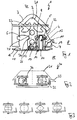
- Die Erfindung wird nachstehend anhand von Ausführungsbeispielen unter Bezugnahme auf die Zeichnung näher erläutert. Dort zeigen
- Figur 1
- schematisch in einem Querschnitt ein hier nicht beanspruchtes Kettenschienenprofil mit einem Vorlaufraum, einem Rücklaufraum und einer darin angeordneten Nadelkette,
- Figur 2
- vereinfacht schematisch in einem Querschnitt ein zweites Ausführungsbeispiel einer Kettenschiene mit einem zweiten Ausführungsbeispiel einer Kette,
- Figur 3
- schematisch in der aus
Figur 2 gewählten Schnittansicht vier Rollkörper mit selbstzentrierenden Eigenschaften für eine Kette, - Figur 4
- schematisch in einem Querschnitt ein Kettenschienenprofil mit Zugrollen mit verdoppelter Auflagelänge und Stützrollen zur Gewichtsentlastung an etwa jedem fünften bis zehnten Glied,
- Figur 5
- schematisch in einem Querschnitt analog zur
Figur 4 eine abgewandelte Ausführungsform, - Figur 6
- schematisch in einem Querschnitt analog zur
Figuren 4 und5 eine weiter abgewandelte Ausführungsform mit Krafteingriff in Rollenmitte, - Figur 7
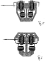
- schematisch in einem Querschnitt mit verkürzter Folienebene ein Kettenschienenpaar mit zwei Antriebskörpern,
- Figur 8
- schematisch in einem Querschnitt analog zur
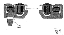
Figur 7 ein Kettenschienenpaar mit einer abgewandelten Konstruktionsweise sowie - Figur 9
- schematisch in einem Querschnitt analog zu den
Figuren 7 und 8 ein Kettenschienenpaar in gleicher Bauweise, mit einem Antriebskörper. - Eine hier nicht beanspruchte Transporteinrichtung 1 in
Figur 1 besteht im Wesentlichen aus einem Kettenschienenprofil 2, einer darauf liegenden Leiste 3 sowie einer Kette 4, welche in einem Vorlaufraum 5 hin- und in einem Rücklaufraum 6 (dort ist die Kette 4 nicht dargestellt) zurückläuft. - Die Transporteinrichtung 1 befindet sich in einer Thermoformanlage. Dort werden mit intermittierendem Transport Thermoformprodukte aus einer Endlosfolienbahn geformt und mit einem Stanzwerkzeug vereinzelt.
- In der Thermoformanlage befindet sich mindestes eine weitere Transporteinrichtung, welche exakt wie die Transporteinrichtung 1 ausgeführt ist, aber spiegelverkehrt. Nadeln 7 der Kette 4 in der gezeigten Transporteinrichtung 1 sowie gegenüberliegenden Nadeln der dortigen Transporteinrichtung greifen also aufeinander zu, sodass in einem Transportraum 8 die Endlosfolienbahn transportiert werden kann, indem die Kette 4 angetrieben wird oder beide Ketten angetrieben werden.
- Die Kette 4 ist in herkömmlicher Weise aufgebaut. Zwischen Außenlaschen 9 (exemplarisch gekennzeichnet) und Innenlaschen 10 (exemplarisch gekennzeichnet) sind Bolzen 11 mit Hülsen (nicht dargestellt) und jeweils einer Rolle 12 angeordnet. Der Vorlaufraum 5 weist an der zum Transportraum 8 hin gerichteten Seite der Rolle 12 eine schienenförmige Gegenkontur 13 passend zur Kontur der Rolle 12 auf.
- Der Bolzen 11 sitzt nicht vertikal zentriert in den Laschen, sondern leicht nach oben versetzt, sodass sich eine glatte Stirn 14 nach unten hin ergibt. Dort befindet sich ein Streifen 15 mit einer Gleitfläche 16. Der Streifen 15 ist mit regelmäßig beabstandeten Rastnasen 17 in einem Aufnahmeraum an einer Unterseite 18 des Kettenschienenprofils 2 befestigt.
- Zum Transportraum 8 hin befindet sich seitlich der Gegenkontur 13 auf etwa gleicher Höhe eine Sicherungsrille 19, in welcher Spitzen der Nadeln 7 laufen.
- An einer Oberseite 20 des Kettenschienenprofils 2 liegt die abgerundet rechtwinklig gebogene Leiste 3 auf dem gesamten Kettenschienenprofil 2. Eine Auflagefläche 21 am Kettenschienenprofil 2 für die Leiste 3 ist stark abgeschrägt, nämlich in einem Winkel von etwa 45° zur Horizontalen. Ebenfalls schräg setzt sich von deren Ende aus eine Seite 22 des Kettenschienenprofils 2 fort, sodass die Sicherungsrille 19 des Kettenschienenprofils 2 deutlich der am weitesten zum Transportraum 8 vorstehende Teil der Transporteinrichtung 1 ist, gemeinsam mit den Nadeln 7.
- An einem Kreuzungspunkt 23 des im Wesentlichen kreuzförmigen Kettenschienenprofils 2 sowie in einem vertikalen Steg darunter befinden sich zwei Kühlbohrungen 25, 26.
- Im Betrieb der Thermoformanlage läuft die Kette 4 mit eingenadelter Endlosfolienbahn durch den Vorlaufraum 5. Am Ende der Transporteinrichtung befindet sich eine Wendestelle. Von dort aus läuft die Kette 4 zurück durch den Rücklaufraum 6 zu einer zweiten Wendestelle und von aus wieder hinein in den Vorlaufraum 5.
- Weil die Endlosfolienbahn im Transportraum 8 in horizontaler Richtung gespannt ist, übt die Endlosfolienbahn über die Nadeln 7 eine Querkraft auf die Kette 4 aus.
- Durch die spezielle Anordnung der Kette 4 kann diese die durch den Verarbeitungsprozess entstehenden Kräfte, die in der Endlosfolienbahn bei Temperaturveränderung entstehen, sowie die daraus entstehenden Zug- und Druckauslastungskräfte so übertragen, dass die Lauffläche zwischen Rolle 12 und Kettenschienenprofil 2 gleichmäßig und großflächig mit geringstem spezifischen Druck belastet wird. Dadurch bleibt sie möglichst frei von Abrieb.
- Die vorbekannten Transportketten in einem Kettenschienenprofil mit vertikalem Umlauf können dadurch vermieden werden. An diesen befanden sich auf einer Seite Stütztrollen, um die durch die Folienspannung entstehenden Schwerkräfte aufzunehmen, und auf der anderen Seite an der Kette die Nadeln, um die Folie zu halten. Aus geometrischen und fertigungsbedingten Gründen ließen sich oft Schwierigkeiten im Hinblick auf den Verschleiß feststellen. Durch das Querkraft-induzierte Kippmoment lagen die Stütz- oder Transportrollen nicht immer vollflächig an der Profilwand an.
- In der hier vorliegenden Ausführungsform wird im Prinzip das Kettenschienenprofil umgelegt, und zwar um 90°, und die Kette läuft dann horizontal um. Dadurch ergibt sich ein günstigerer Kräfteverlauf auf die Stütz- und Zugrolle. Es ergibt sich eine rein rollende Belastung. Die Kette verspannt nicht.
- Zusätzlich ist die Kette 4 in vertikaler Hinsicht selbstzentrierend: in Folge der Querkraft hin zum Transportraum wird die Rolle 12 mit ihrer oktagonalen Außenkontur in die Gegenkontur 13 hineingezogen. Die Außenkontur der Rolle 12 ist konvex, die Innenkontur der Gegenkontur 13 an der Profilschiene hingegen konkav. Auf diese Weise wird gewährleistet, dass die Rolle 13 die Last am Kettenschienenprofil 2 abträgt.
- Zusätzlich ist die Gleitfläche 16 am Bodenstreifen 15 vorgesehen. Die Kette 4 gleitet somit in der Vertikalachse auf den Gleitelementen in Folge ihres Eigengewichts auf der Gleitfläche 16. Dies ist insbesondere beim Rücklauf im Rücklaufraum 6 zu beobachten, weil dort keine Querkraft auf die Kette ausgeübt wird, welche die Kette etwa vertikal zentrieren könnte.
- In Folge des an Oberseite 20 und Seite 22 schräg ausgebildeten Kettenschienenprofils 2 kann die eingenadelte Folie von Heizkörpern in einem Heizkörperbereich 27 praktisch bis zu ihrem Rand beheizt werden.
- Bei der zweiten Ausführungsform einer Transporteinrichtung 30 in
Figur 2 sind ein Kettenschienenprofil 31 und eine Kettenrolle 32 sowohl in horizontaler als auch in vertikaler Hinsicht selbstzentrierend aufeinander abgestimmt, sodass sowohl eine Querkraft 33 als auch eine Schwerkraft 34 jeweils zu einer Selbstzentrierung führen, nämlich die Querkraft 33 in vertikaler Hinsicht und die Schwerkraft 34 in horizontaler Hinsicht. - Verschiedene weitere Ausführungsformen für selbstzentrierbare Rollen sind in
Figur 3 dargestellt. - Die Erfindung betrifft eine Thermoformanlage zum Bearbeiten einer Kunststofflage, welche für den Verarbeitungsverlauf bei präzis-angepasstem Rhythmus im benötigten Einzug der Rollen- oder Plattenform zur Verfügung stehenden Folienbahn zur Kunststoffverarbeitungsmaschine, der sicheren Weitertransportierbarkeit durch bzw. entlang diverse Verarbeitungsprozesse bis zur Endbearbeitung der Materialbahn und zum Ablegen oder Stapeln des Endprodukts verbessert ist.
- Herkömmliche Verfahren und Anlagen passen sich nicht gut an die Erfordernisse moderner Kunststoffe und derer Verarbeitungstechnologien an. Sie unterliegen einem hohen Verschleiß. Dies führt zu kostenintensivem Handling, frühzeitigem Austauschen von Bauteilen und teils schlechthin Endergebnissen des Endproduktes.
- Aufgabe des neu vorgestellten Verfahrens mit der neu vorgestellten Vorrichtung ist es, eine Kunststofffolienbahn 41 zu führen. Ein hierzu speziell aufgebautes, profiliertes, druck-, temperatur- und korrosionsbeständiges Leit-Schienenpaar 42 wird hierzu eingesetzt. Dieses arbeitet im Parallelbetrieb und ist in der Lage, ein Rollenkettenpaar 43 aufzunehmen. Das Rollenkettenpaar ist mit einer Anzahl Anhängeelemente 47, beispielsweise in Form von Haken oder Nadeln, ausgestattet.
- Das Leit-Schienenpaar 42 führt das Rollenkettenpaar 43 dreiseitig gestützt und reibungslos rollend. Zur Ableitung von entstehender Abwärme ist das Leit-Schienenpaar 42 mit Bohrungen 44 zum Durchleiten von Kühlfluid versehen.
- Rollen 45 des Rollenkettenpaares 43 haben eine stehende Arbeitsweise. Für den Fall eines eventuellen Trockenlaufes der Gleitfläche zwischen Rollen 45 und Achsen in Form eines Bolzens wurden letztere mit axialen Durchbohrungen 49 in einer Hülse versehen, wodurch in vertikaler Richtung ein Schmiermittellauf ermöglicht wird, welcher über Seitenöffnung 50 austreten kann.
- Die Last des Rollenkettenpaares 43 wird über ein Verbindungselement 51 auf eine im unteren Bereich des Systems befindliche Bolzenkette 46 übertragen. Die Bolzenkette 46 dient als Trag- und Laufelement. Sie ist mit vergrößerten Rollenflächen versehen. Auch ihre Last wird letztendlich vom Leit-Schienenpaar 42 abgetragen.
- Zum Vorsehen der axialen Durchbohrung 49 und der Seitenöffnung 50 kann einfach ein voller Bolzen durch einen Rohrbolzen ersetzt werden. Der zentrale Kanal weist bevorzugt eine Filzbefüllung auf. Sodann kann durch die horizontale Schmierkanäle ausreichend Schmierflüssigkeit austreten.
- Anwendungsabhängig kann das Transportsystem so ausgelegt werden, dass die Folienbahn von unten (vgl. insbesondere
Figuren 4 ,6 und7 ) oder von oben (vgl. insbesondereFiguren 5 ,8 und9 ) erfasst, also von den Nadeln durchstochen, wird. Der Antrieb der Ketten wird kopfseitig vorgenommen und kann anlagenbedingt wahlweise über einen waagerechten Ritzeleingriff 52 mit vertikaler Achse ausgelegt sein, oder von bevorzugt unten mit vertikalem Ritzel bei liegender Achse 53. - Die Ausführungsformen in den
Figuren 5, 6 ,7, 8 und9 sehen vor, dass die Querkraft aus der Folienebene etwa mittig auf die Rollen der aufrecht angeordneten Kettenglieder wirkt, was nochmals zu einer verlängerten Lebensdauer des Transportsystems führen kann. - Gleiches gilt für den zwischen Zugkettengliedern und Stützrollen gelegten Kraftübertragungspunkt in den
Figuren 6 ,7 und9 .
Claims (2)
- Thermoformanlage zum Bearbeiten einer Kunststofflage, mit einer Kette (4) zum Transport der Kunststofflage durch die Thermoformanlage, wobei die Kette (4) ein Haltemittel (47) für die Kunststofflage (41) aufweist, sodass die Kunststofflage (41) im Betrieb der Thermoformanlage über das Haltemittel (47) quer zu einer Kettenverlaufsrichtung eine Querkraft (33) auf die Kette (4) ausüben kann, sowie mit einer Führung für die Kette (4) zum Aufnehmen der Querkraft (33), wobei die Kette (4) eine Grundstruktur mit einer Vielzahl Rollen (45) zwischen Laschen zur Aufnahme einer Transportrichtungskraft aufweist, wobei die Rollen (45) aufrecht orientiert sind, sodass die Querkraft (33) quer zu ihren Rollenachsen wirkt, wobei also die Rollen (45) mit einer aufrechten Achse stehend arbeiten, wobei die Führung direkt an den Rollen (45) angreift,
dadurch gekennzeichnet, dass
sich die Kette (4) vertikal auf Schwerkraftstützrollen aufstützt und wobei die Schwerkraftstützrollen separat von den Rollen (45) ausgebildet sind und eine liegende Achse haben. - Thermoformanlage nach Anspruch 1, dadurch gekennzeichnet, dass die Kette (4) in einem Kettenschienenprofil (42) umläuft und eine Grundstruktur mit der Vielzahl der Rollen (45) zwischen Laschen zur Aufnahme einer Transportrichtungskraft aufweist, wobei das Kettenschienenprofil (42) einen spiegelsymmetrischen Querschnitt mit einer aufrecht orientierten Symmetrieachse aufweist.
Applications Claiming Priority (3)
| Application Number | Priority Date | Filing Date | Title |
|---|---|---|---|
| DE102010022859 | 2010-06-07 | ||
| DE102011012882A DE102011012882A1 (de) | 2010-06-07 | 2011-03-02 | Thermoformanlage, Transportsystem und hiermit hergestelltes Thermoformprodukt |
| PCT/DE2011/000380 WO2011153976A2 (de) | 2010-06-07 | 2011-04-11 | Thermoformanlage, transportsystem und hiermit hergestelltes thermoformprodukt |
Publications (2)
| Publication Number | Publication Date |
|---|---|
| EP2576185A2 EP2576185A2 (de) | 2013-04-10 |
| EP2576185B1 true EP2576185B1 (de) | 2019-08-28 |
Family
ID=44630307
Family Applications (1)
| Application Number | Title | Priority Date | Filing Date |
|---|---|---|---|
| EP11743766.5A Active EP2576185B1 (de) | 2010-06-07 | 2011-04-11 | Thermoformanlage aufweisendes transportsystem |
Country Status (4)
| Country | Link |
|---|---|
| US (1) | US9744713B2 (de) |
| EP (1) | EP2576185B1 (de) |
| DE (1) | DE102011012882A1 (de) |
| WO (1) | WO2011153976A2 (de) |
Families Citing this family (2)
| Publication number | Priority date | Publication date | Assignee | Title |
|---|---|---|---|---|
| DE102013011953A1 (de) * | 2013-07-18 | 2015-01-22 | Brückner Maschinenbau GmbH & Co. KG | Seitenführungsschiene für ein Transportsystem, insbesondere eine Reckanlage |
| CN114309856A (zh) * | 2022-03-15 | 2022-04-12 | 深圳市捷豹自动化设备有限公司 | 真空回流焊导轨 |
Citations (6)
| Publication number | Priority date | Publication date | Assignee | Title |
|---|---|---|---|---|
| FR452978A (fr) * | 1913-01-09 | 1913-05-28 | Hoe & Co R | Mécanisme livreur de feuilles, pour machines à imprimer et autres |
| DE2062506A1 (de) * | 1970-12-18 | 1972-06-29 | Siemag Siegener Masch Bau | |
| DE2335246A1 (de) * | 1973-07-11 | 1975-01-30 | Rudolf Lensing | Folienvorschub in kunststoffverarbei-tungsmaschinen |
| DE19629196A1 (de) * | 1996-07-19 | 1998-01-22 | Frimo Huber Systemtechnik Gmbh | Thermoformvorrichtung |
| DE29816386U1 (de) * | 1998-09-11 | 1999-02-25 | Paul Kiefel GmbH, 83395 Freilassing | Transportvorrichtung für Folien und Platten bei Thermoform-Maschinen |
| DE29910064U1 (de) * | 1999-06-09 | 1999-09-16 | Paul Kiefel GmbH, 83395 Freilassing | Thermoformvorrichtung |
Family Cites Families (12)
| Publication number | Priority date | Publication date | Assignee | Title |
|---|---|---|---|---|
| US3321561A (en) | 1964-07-24 | 1967-05-23 | Brown Machine Co Of Michigan | Methods for treating organic plastic sheet to be differential pressure formed |
| US3611481A (en) | 1969-09-22 | 1971-10-12 | Standard Oil Co | Molding apparatus having sheet transporting means with piercer means thereon |
| US3828997A (en) * | 1973-05-30 | 1974-08-13 | United Ind Syndicate | Apparatus for positively conveying sheet materials |
| IT1021438B (it) * | 1974-09-17 | 1978-01-30 | Frigo Vito | Macchina per calzare in posizione stesa su una pluralita di telai materiali in nastro continuo |
| US4196164A (en) * | 1974-10-04 | 1980-04-01 | Plastona (John Waddington) Ltd. | Manufacture of plastics material articles |
| US4101252A (en) * | 1976-05-14 | 1978-07-18 | Sweetheart Plastic, Inc. | Sheet support apparatus |
| DE2937542C2 (de) * | 1979-09-17 | 1983-11-24 | Adolf Illig Maschinenbau Gmbh & Co, 7100 Heilbronn | Thermoformmaschine mit einer nachgeschalteten Stanzeinrichtung |
| JPS601260B2 (ja) * | 1980-12-08 | 1985-01-12 | 株式会社 浅野研究所 | 連続樹脂シ−トの切断・供給装置 |
| US4428723A (en) * | 1982-02-18 | 1984-01-31 | Thiel Alfons W | Apparatus for stretching a continuously advancing synthetic-resin web and feeding same stepwise to a thermoforming machine |
| EP0346815A3 (de) * | 1988-06-13 | 1990-12-19 | Asahi Glass Company Ltd. | Vakuumbehandlungsvorrichtung und deren Transportsystem |
| US4954066A (en) | 1988-12-20 | 1990-09-04 | Cincinnati Milacron Inc. | Thermoforming and conveyor chain guide apparatus |
| JPH10305480A (ja) | 1997-05-06 | 1998-11-17 | Waikomu Seiki Kk | 熱可塑性樹脂シート搬送チェーンのシートクリップ装置 |
-
2011
- 2011-03-02 DE DE102011012882A patent/DE102011012882A1/de not_active Withdrawn
- 2011-04-11 US US13/702,420 patent/US9744713B2/en not_active Expired - Fee Related
- 2011-04-11 EP EP11743766.5A patent/EP2576185B1/de active Active
- 2011-04-11 WO PCT/DE2011/000380 patent/WO2011153976A2/de not_active Ceased
Patent Citations (6)
| Publication number | Priority date | Publication date | Assignee | Title |
|---|---|---|---|---|
| FR452978A (fr) * | 1913-01-09 | 1913-05-28 | Hoe & Co R | Mécanisme livreur de feuilles, pour machines à imprimer et autres |
| DE2062506A1 (de) * | 1970-12-18 | 1972-06-29 | Siemag Siegener Masch Bau | |
| DE2335246A1 (de) * | 1973-07-11 | 1975-01-30 | Rudolf Lensing | Folienvorschub in kunststoffverarbei-tungsmaschinen |
| DE19629196A1 (de) * | 1996-07-19 | 1998-01-22 | Frimo Huber Systemtechnik Gmbh | Thermoformvorrichtung |
| DE29816386U1 (de) * | 1998-09-11 | 1999-02-25 | Paul Kiefel GmbH, 83395 Freilassing | Transportvorrichtung für Folien und Platten bei Thermoform-Maschinen |
| DE29910064U1 (de) * | 1999-06-09 | 1999-09-16 | Paul Kiefel GmbH, 83395 Freilassing | Thermoformvorrichtung |
Also Published As
| Publication number | Publication date |
|---|---|
| WO2011153976A2 (de) | 2011-12-15 |
| US9744713B2 (en) | 2017-08-29 |
| WO2011153976A3 (de) | 2012-05-31 |
| EP2576185A2 (de) | 2013-04-10 |
| US20130108836A1 (en) | 2013-05-02 |
| DE102011012882A1 (de) | 2011-12-08 |
Similar Documents
| Publication | Publication Date | Title |
|---|---|---|
| EP2849929B1 (de) | Blasfolienanlage, verfahren zum herstellen einer blasfolienbahn und damit hergestellte folie | |
| EP2962966B1 (de) | Anlage zum herstellen eines medizinprodukts sowie verfahren zum betreiben einer solchen anlage | |
| EP2412650B1 (de) | Speichervorrichtung für Behälter und Verfahren zum Speichern von Behältern | |
| EP3315420B1 (de) | Tiefziehverpackungsmaschine | |
| EP3302927B1 (de) | Führungseinrichtung und verfahren zum führen einer kunststofffolie | |
| EP3808537A1 (de) | Kluppenwagen für eine transportkettenanordnung einer reckanlage sowie eine zugehörige reckanlage | |
| DE2648025A1 (de) | Vorgefertigte isolierende platte sowie anlage fuer deren kontinuierliche herstellung | |
| AT501192B1 (de) | Vorrichtung zum transportieren und stützen tafelförmiger gegenstände, insbesondere glastafeln | |
| EP3057769B1 (de) | Kluppen-transporteinheit | |
| DE10235151B4 (de) | Haltevorrichtung für eine Extrusionsdüse | |
| DE102012102208B4 (de) | Automatische Presse zum Querleimen massiver lamellenartiger Elemente | |
| DE102011012882A1 (de) | Thermoformanlage, Transportsystem und hiermit hergestelltes Thermoformprodukt | |
| EP3452265B1 (de) | Heizvorrichtung für eine blasmaschine mit faltbarer förderkette | |
| DE19629196C2 (de) | Thermoformvorrichtung | |
| EP4118018B1 (de) | Beladesystem | |
| AT508038B1 (de) | Sägemaschine | |
| DE102014102562B4 (de) | Presse, Fertigungsanlage und Verfahren zur Herstellung eines faserverstärkten Werkstoffes sowie Heizplatte einer Presse | |
| DE69911447T2 (de) | Schweissstrang zum herstellen von querschweissnähten in einem folienblatt | |
| AT526905B1 (de) | Durchlaufkühlvorrichtung | |
| DE102010005110A1 (de) | Rollenbahn mit werkzeugloser Verbindung der Längsträger | |
| EP2792627B1 (de) | Docking-System | |
| DE1454994A1 (de) | Verfahren und Vorrichtung zur Vorbereitung von thermoplastischen Kunststoffolien fuer die Differentialdruckverformung | |
| WO2018103900A1 (de) | Transportvorrichtung | |
| DD202117A5 (de) | Verfahren und vorrichtung zur herstellung von profile aufweisenden bahnen oder platten | |
| WO2025125381A1 (de) | Vorrichtung zum omnidirektionalen fördern von biegeschlaffen förderguteinheiten |
Legal Events
| Date | Code | Title | Description |
|---|---|---|---|
| PUAI | Public reference made under article 153(3) epc to a published international application that has entered the european phase |
Free format text: ORIGINAL CODE: 0009012 |
|
| 17P | Request for examination filed |
Effective date: 20121211 |
|
| AK | Designated contracting states |
Kind code of ref document: A2 Designated state(s): AL AT BE BG CH CY CZ DE DK EE ES FI FR GB GR HR HU IE IS IT LI LT LU LV MC MK MT NL NO PL PT RO RS SE SI SK SM TR |
|
| DAX | Request for extension of the european patent (deleted) | ||
| RAP1 | Party data changed (applicant data changed or rights of an application transferred) |
Owner name: KIEFEL GMBH |
|
| 17Q | First examination report despatched |
Effective date: 20150619 |
|
| STAA | Information on the status of an ep patent application or granted ep patent |
Free format text: STATUS: EXAMINATION IS IN PROGRESS |
|
| GRAP | Despatch of communication of intention to grant a patent |
Free format text: ORIGINAL CODE: EPIDOSNIGR1 |
|
| STAA | Information on the status of an ep patent application or granted ep patent |
Free format text: STATUS: GRANT OF PATENT IS INTENDED |
|
| RIC1 | Information provided on ipc code assigned before grant |
Ipc: B29C 55/08 20060101ALN20190213BHEP Ipc: B29C 55/04 20060101ALN20190213BHEP Ipc: B65G 21/22 20060101ALN20190213BHEP Ipc: B29C 51/18 20060101ALN20190213BHEP Ipc: B29C 55/02 20060101ALN20190213BHEP Ipc: B65G 17/00 20060101ALI20190213BHEP Ipc: B29C 51/42 20060101ALN20190213BHEP Ipc: B29C 51/24 20060101ALN20190213BHEP Ipc: B29C 51/26 20060101AFI20190213BHEP Ipc: B29C 51/20 20060101ALN20190213BHEP |
|
| RIC1 | Information provided on ipc code assigned before grant |
Ipc: B29C 51/20 20060101ALN20190219BHEP Ipc: B29C 55/08 20060101ALN20190219BHEP Ipc: B29C 51/42 20060101ALN20190219BHEP Ipc: B29C 51/26 20060101AFI20190219BHEP Ipc: B65G 21/22 20060101ALN20190219BHEP Ipc: B29C 55/02 20060101ALN20190219BHEP Ipc: B65G 17/00 20060101ALI20190219BHEP Ipc: B29C 55/04 20060101ALN20190219BHEP Ipc: B29C 51/24 20060101ALN20190219BHEP Ipc: B29C 51/18 20060101ALN20190219BHEP |
|
| RIC1 | Information provided on ipc code assigned before grant |
Ipc: B65G 17/00 20060101ALI20190222BHEP Ipc: B29C 55/02 20060101ALN20190222BHEP Ipc: B65G 21/22 20060101ALN20190222BHEP Ipc: B29C 51/18 20060101ALN20190222BHEP Ipc: B29C 55/04 20060101ALN20190222BHEP Ipc: B29C 55/08 20060101ALN20190222BHEP Ipc: B29C 51/26 20060101AFI20190222BHEP Ipc: B29C 51/20 20060101ALN20190222BHEP Ipc: B29C 51/42 20060101ALN20190222BHEP Ipc: B29C 51/24 20060101ALN20190222BHEP |
|
| INTG | Intention to grant announced |
Effective date: 20190314 |
|
| RIC1 | Information provided on ipc code assigned before grant |
Ipc: B29C 55/02 20060101ALN20190304BHEP Ipc: B65G 17/00 20060101ALI20190304BHEP Ipc: B29C 51/42 20060101ALN20190304BHEP Ipc: B29C 51/24 20060101ALN20190304BHEP Ipc: B29C 51/18 20060101ALN20190304BHEP Ipc: B29C 51/20 20060101ALN20190304BHEP Ipc: B29C 55/08 20060101ALN20190304BHEP Ipc: B29C 51/26 20060101AFI20190304BHEP Ipc: B65G 21/22 20060101ALN20190304BHEP Ipc: B29C 55/04 20060101ALN20190304BHEP |
|
| GRAS | Grant fee paid |
Free format text: ORIGINAL CODE: EPIDOSNIGR3 |
|
| GRAA | (expected) grant |
Free format text: ORIGINAL CODE: 0009210 |
|
| STAA | Information on the status of an ep patent application or granted ep patent |
Free format text: STATUS: THE PATENT HAS BEEN GRANTED |
|
| AK | Designated contracting states |
Kind code of ref document: B1 Designated state(s): AL AT BE BG CH CY CZ DE DK EE ES FI FR GB GR HR HU IE IS IT LI LT LU LV MC MK MT NL NO PL PT RO RS SE SI SK SM TR |
|
| REG | Reference to a national code |
Ref country code: GB Ref legal event code: FG4D Free format text: NOT ENGLISH |
|
| REG | Reference to a national code |
Ref country code: CH Ref legal event code: EP |
|
| REG | Reference to a national code |
Ref country code: AT Ref legal event code: REF Ref document number: 1171866 Country of ref document: AT Kind code of ref document: T Effective date: 20190915 |
|
| REG | Reference to a national code |
Ref country code: IE Ref legal event code: FG4D Free format text: LANGUAGE OF EP DOCUMENT: GERMAN |
|
| REG | Reference to a national code |
Ref country code: DE Ref legal event code: R096 Ref document number: 502011016049 Country of ref document: DE |
|
| REG | Reference to a national code |
Ref country code: NL Ref legal event code: MP Effective date: 20190828 |
|
| REG | Reference to a national code |
Ref country code: LT Ref legal event code: MG4D |
|
| PG25 | Lapsed in a contracting state [announced via postgrant information from national office to epo] |
Ref country code: BG Free format text: LAPSE BECAUSE OF FAILURE TO SUBMIT A TRANSLATION OF THE DESCRIPTION OR TO PAY THE FEE WITHIN THE PRESCRIBED TIME-LIMIT Effective date: 20191128 Ref country code: NL Free format text: LAPSE BECAUSE OF FAILURE TO SUBMIT A TRANSLATION OF THE DESCRIPTION OR TO PAY THE FEE WITHIN THE PRESCRIBED TIME-LIMIT Effective date: 20190828 Ref country code: SE Free format text: LAPSE BECAUSE OF FAILURE TO SUBMIT A TRANSLATION OF THE DESCRIPTION OR TO PAY THE FEE WITHIN THE PRESCRIBED TIME-LIMIT Effective date: 20190828 Ref country code: NO Free format text: LAPSE BECAUSE OF FAILURE TO SUBMIT A TRANSLATION OF THE DESCRIPTION OR TO PAY THE FEE WITHIN THE PRESCRIBED TIME-LIMIT Effective date: 20191128 Ref country code: PT Free format text: LAPSE BECAUSE OF FAILURE TO SUBMIT A TRANSLATION OF THE DESCRIPTION OR TO PAY THE FEE WITHIN THE PRESCRIBED TIME-LIMIT Effective date: 20191230 Ref country code: FI Free format text: LAPSE BECAUSE OF FAILURE TO SUBMIT A TRANSLATION OF THE DESCRIPTION OR TO PAY THE FEE WITHIN THE PRESCRIBED TIME-LIMIT Effective date: 20190828 Ref country code: LT Free format text: LAPSE BECAUSE OF FAILURE TO SUBMIT A TRANSLATION OF THE DESCRIPTION OR TO PAY THE FEE WITHIN THE PRESCRIBED TIME-LIMIT Effective date: 20190828 Ref country code: HR Free format text: LAPSE BECAUSE OF FAILURE TO SUBMIT A TRANSLATION OF THE DESCRIPTION OR TO PAY THE FEE WITHIN THE PRESCRIBED TIME-LIMIT Effective date: 20190828 |
|
| PG25 | Lapsed in a contracting state [announced via postgrant information from national office to epo] |
Ref country code: GR Free format text: LAPSE BECAUSE OF FAILURE TO SUBMIT A TRANSLATION OF THE DESCRIPTION OR TO PAY THE FEE WITHIN THE PRESCRIBED TIME-LIMIT Effective date: 20191129 Ref country code: LV Free format text: LAPSE BECAUSE OF FAILURE TO SUBMIT A TRANSLATION OF THE DESCRIPTION OR TO PAY THE FEE WITHIN THE PRESCRIBED TIME-LIMIT Effective date: 20190828 Ref country code: IS Free format text: LAPSE BECAUSE OF FAILURE TO SUBMIT A TRANSLATION OF THE DESCRIPTION OR TO PAY THE FEE WITHIN THE PRESCRIBED TIME-LIMIT Effective date: 20191228 Ref country code: RS Free format text: LAPSE BECAUSE OF FAILURE TO SUBMIT A TRANSLATION OF THE DESCRIPTION OR TO PAY THE FEE WITHIN THE PRESCRIBED TIME-LIMIT Effective date: 20190828 Ref country code: AL Free format text: LAPSE BECAUSE OF FAILURE TO SUBMIT A TRANSLATION OF THE DESCRIPTION OR TO PAY THE FEE WITHIN THE PRESCRIBED TIME-LIMIT Effective date: 20190828 Ref country code: ES Free format text: LAPSE BECAUSE OF FAILURE TO SUBMIT A TRANSLATION OF THE DESCRIPTION OR TO PAY THE FEE WITHIN THE PRESCRIBED TIME-LIMIT Effective date: 20190828 |
|
| PG25 | Lapsed in a contracting state [announced via postgrant information from national office to epo] |
Ref country code: TR Free format text: LAPSE BECAUSE OF FAILURE TO SUBMIT A TRANSLATION OF THE DESCRIPTION OR TO PAY THE FEE WITHIN THE PRESCRIBED TIME-LIMIT Effective date: 20190828 |
|
| PG25 | Lapsed in a contracting state [announced via postgrant information from national office to epo] |
Ref country code: PL Free format text: LAPSE BECAUSE OF FAILURE TO SUBMIT A TRANSLATION OF THE DESCRIPTION OR TO PAY THE FEE WITHIN THE PRESCRIBED TIME-LIMIT Effective date: 20190828 Ref country code: DK Free format text: LAPSE BECAUSE OF FAILURE TO SUBMIT A TRANSLATION OF THE DESCRIPTION OR TO PAY THE FEE WITHIN THE PRESCRIBED TIME-LIMIT Effective date: 20190828 Ref country code: IT Free format text: LAPSE BECAUSE OF FAILURE TO SUBMIT A TRANSLATION OF THE DESCRIPTION OR TO PAY THE FEE WITHIN THE PRESCRIBED TIME-LIMIT Effective date: 20190828 Ref country code: EE Free format text: LAPSE BECAUSE OF FAILURE TO SUBMIT A TRANSLATION OF THE DESCRIPTION OR TO PAY THE FEE WITHIN THE PRESCRIBED TIME-LIMIT Effective date: 20190828 Ref country code: RO Free format text: LAPSE BECAUSE OF FAILURE TO SUBMIT A TRANSLATION OF THE DESCRIPTION OR TO PAY THE FEE WITHIN THE PRESCRIBED TIME-LIMIT Effective date: 20190828 |
|
| PG25 | Lapsed in a contracting state [announced via postgrant information from national office to epo] |
Ref country code: IS Free format text: LAPSE BECAUSE OF FAILURE TO SUBMIT A TRANSLATION OF THE DESCRIPTION OR TO PAY THE FEE WITHIN THE PRESCRIBED TIME-LIMIT Effective date: 20200224 Ref country code: CZ Free format text: LAPSE BECAUSE OF FAILURE TO SUBMIT A TRANSLATION OF THE DESCRIPTION OR TO PAY THE FEE WITHIN THE PRESCRIBED TIME-LIMIT Effective date: 20190828 Ref country code: SK Free format text: LAPSE BECAUSE OF FAILURE TO SUBMIT A TRANSLATION OF THE DESCRIPTION OR TO PAY THE FEE WITHIN THE PRESCRIBED TIME-LIMIT Effective date: 20190828 Ref country code: SM Free format text: LAPSE BECAUSE OF FAILURE TO SUBMIT A TRANSLATION OF THE DESCRIPTION OR TO PAY THE FEE WITHIN THE PRESCRIBED TIME-LIMIT Effective date: 20190828 |
|
| REG | Reference to a national code |
Ref country code: DE Ref legal event code: R097 Ref document number: 502011016049 Country of ref document: DE |
|
| PLBE | No opposition filed within time limit |
Free format text: ORIGINAL CODE: 0009261 |
|
| STAA | Information on the status of an ep patent application or granted ep patent |
Free format text: STATUS: NO OPPOSITION FILED WITHIN TIME LIMIT |
|
| PG2D | Information on lapse in contracting state deleted |
Ref country code: IS |
|
| 26N | No opposition filed |
Effective date: 20200603 |
|
| PG25 | Lapsed in a contracting state [announced via postgrant information from national office to epo] |
Ref country code: SI Free format text: LAPSE BECAUSE OF FAILURE TO SUBMIT A TRANSLATION OF THE DESCRIPTION OR TO PAY THE FEE WITHIN THE PRESCRIBED TIME-LIMIT Effective date: 20190828 |
|
| REG | Reference to a national code |
Ref country code: DE Ref legal event code: R119 Ref document number: 502011016049 Country of ref document: DE |
|
| PG25 | Lapsed in a contracting state [announced via postgrant information from national office to epo] |
Ref country code: MC Free format text: LAPSE BECAUSE OF FAILURE TO SUBMIT A TRANSLATION OF THE DESCRIPTION OR TO PAY THE FEE WITHIN THE PRESCRIBED TIME-LIMIT Effective date: 20190828 |
|
| REG | Reference to a national code |
Ref country code: CH Ref legal event code: PL |
|
| PG25 | Lapsed in a contracting state [announced via postgrant information from national office to epo] |
Ref country code: LU Free format text: LAPSE BECAUSE OF NON-PAYMENT OF DUE FEES Effective date: 20200411 Ref country code: CH Free format text: LAPSE BECAUSE OF NON-PAYMENT OF DUE FEES Effective date: 20200430 Ref country code: FR Free format text: LAPSE BECAUSE OF NON-PAYMENT OF DUE FEES Effective date: 20200430 Ref country code: DE Free format text: LAPSE BECAUSE OF NON-PAYMENT OF DUE FEES Effective date: 20201103 Ref country code: LI Free format text: LAPSE BECAUSE OF NON-PAYMENT OF DUE FEES Effective date: 20200430 |
|
| REG | Reference to a national code |
Ref country code: BE Ref legal event code: MM Effective date: 20200430 |
|
| PG25 | Lapsed in a contracting state [announced via postgrant information from national office to epo] |
Ref country code: BE Free format text: LAPSE BECAUSE OF NON-PAYMENT OF DUE FEES Effective date: 20200430 |
|
| GBPC | Gb: european patent ceased through non-payment of renewal fee |
Effective date: 20200411 |
|
| PG25 | Lapsed in a contracting state [announced via postgrant information from national office to epo] |
Ref country code: IE Free format text: LAPSE BECAUSE OF NON-PAYMENT OF DUE FEES Effective date: 20200411 Ref country code: GB Free format text: LAPSE BECAUSE OF NON-PAYMENT OF DUE FEES Effective date: 20200411 |
|
| REG | Reference to a national code |
Ref country code: AT Ref legal event code: MM01 Ref document number: 1171866 Country of ref document: AT Kind code of ref document: T Effective date: 20200411 |
|
| PG25 | Lapsed in a contracting state [announced via postgrant information from national office to epo] |
Ref country code: AT Free format text: LAPSE BECAUSE OF NON-PAYMENT OF DUE FEES Effective date: 20200411 |
|
| PG25 | Lapsed in a contracting state [announced via postgrant information from national office to epo] |
Ref country code: MT Free format text: LAPSE BECAUSE OF FAILURE TO SUBMIT A TRANSLATION OF THE DESCRIPTION OR TO PAY THE FEE WITHIN THE PRESCRIBED TIME-LIMIT Effective date: 20190828 Ref country code: CY Free format text: LAPSE BECAUSE OF FAILURE TO SUBMIT A TRANSLATION OF THE DESCRIPTION OR TO PAY THE FEE WITHIN THE PRESCRIBED TIME-LIMIT Effective date: 20190828 |
|
| PG25 | Lapsed in a contracting state [announced via postgrant information from national office to epo] |
Ref country code: MK Free format text: LAPSE BECAUSE OF FAILURE TO SUBMIT A TRANSLATION OF THE DESCRIPTION OR TO PAY THE FEE WITHIN THE PRESCRIBED TIME-LIMIT Effective date: 20190828 |